US6990124B1 - SS7-Internet gateway access signaling protocol - Google Patents
SS7-Internet gateway access signaling protocol Download PDFInfo
- Publication number
- US6990124B1 US6990124B1 US09/246,578 US24657899A US6990124B1 US 6990124 B1 US6990124 B1 US 6990124B1 US 24657899 A US24657899 A US 24657899A US 6990124 B1 US6990124 B1 US 6990124B1
- Authority
- US
- United States
- Prior art keywords
- gateway
- access server
- message
- sending
- status
- Prior art date
- Legal status (The legal status is an assumption and is not a legal conclusion. Google has not performed a legal analysis and makes no representation as to the accuracy of the status listed.)
- Expired - Fee Related
Links
Images


Classifications
-
- H—ELECTRICITY
- H04—ELECTRIC COMMUNICATION TECHNIQUE
- H04L—TRANSMISSION OF DIGITAL INFORMATION, e.g. TELEGRAPHIC COMMUNICATION
- H04L63/00—Network architectures or network communication protocols for network security
- H04L63/12—Applying verification of the received information
- H04L63/123—Applying verification of the received information received data contents, e.g. message integrity
-
- H—ELECTRICITY
- H04—ELECTRIC COMMUNICATION TECHNIQUE
- H04M—TELEPHONIC COMMUNICATION
- H04M7/00—Arrangements for interconnection between switching centres
- H04M7/12—Arrangements for interconnection between switching centres for working between exchanges having different types of switching equipment, e.g. power-driven and step by step or decimal and non-decimal
- H04M7/1205—Arrangements for interconnection between switching centres for working between exchanges having different types of switching equipment, e.g. power-driven and step by step or decimal and non-decimal where the types of switching equipement comprises PSTN/ISDN equipment and switching equipment of networks other than PSTN/ISDN, e.g. Internet Protocol networks
- H04M7/126—Interworking of session control protocols
Definitions
- the present invention is related to data communications.
- the present invention is related to a gateway architecture for supporting interworking of a Public Switched Telephone Network (PSTN) Signaling System 7(SS7)-based out-of-band signaling network with a data network such as the Internet or an intranet.
- PSTN Public Switched Telephone Network
- SS7 Signaling System 7
- PSTN Public Switched Telephone Network
- out-of-band signaling is signaling that occurs over a separate signaling link (e.g., link 110 and link 111 ) rather than the trunk (e.g., time division multiplexed (TDM) lines 115 ) over which transmission of user information, e.g., in the form of voice or data transmissions, occur.
- the trunk e.g., time division multiplexed (TDM) lines 115
- user information e.g., in the form of voice or data transmissions
- Signaling System 7 is a standard defined by the International Telecommunications Union (ITU) Telecommunications Standardization Sector (ITU-T).
- ITU-T International Telecommunications Union
- the standard defines the procedures and protocol that supports out-of-band signaling between telecommunications network elements to effect call set up (either wireline or wireless communications), routing and control, using a Common Channel Signaling (CCS) network. Variations under the standard are promulgated by the American National Standards Institute (ANSI), Bellcore, and the European Telecommunications Standards Institute (ETSI).
- a PSTN transmits signaling information, e.g., call setup, etc., over dedicated out-of-band signaling links, typically 56 or 64 kilobits per second (kpbs) bidirectional links), rather than transmitting the control information in-band over voice channels.
- signaling information e.g., call setup, etc.
- dedicated out-of-band signaling links typically 56 or 64 kilobits per second (kpbs) bidirectional links
- An SS7 signaling network 105 that is, an out-of-band signaling network that operates in accordance with the SS7 procedures and protocol, has three fundamental components.
- the components are signaling, or service, switching points(SSPs), signal transfer points (STPs), and signal, or service, control points (SCPs).
- SSPs are PSTN switches, also referred to as Central Office (CO) switches, such as PSTN switches 101 and 102 , that are controlled by SS7 software to originate, terminate and switch calls via the SS7 out-of-band signaling network, hereinafter referred to as the SS7 signaling network or SS7 network.
- CO Central Office
- STPs such as STP 103 within the SS7 network 105 , route signaling information throughout the SS7 network to the appropriate destination network element.
- Service Control Points such as SCP 120 are essentially databases accessed in the SS7 network to, for example, provide information for call processing.
- Signaling points are uniquely identified in the SS7 network by numeric point codes that are included in the signaling messages transmitted between signaling points to uniquely identify the source and destination signaling points for the messages. Routing tables associate a point code with a path through the SS7 network so that a source signaling point can transmit a message to a destination signaling point in the SS7 network.
- An STP is a packet switch that routes incoming messages it receives to a signaling link according to routing information contained in the SS7 messages.
- SS7 signaling links is are characterized differently according to their use.
- the SS7 protocol defines A, B, C, D, E and F links.
- a links 110 , 111 and 112 (“access links”) interconnect STP 103 to either an SSP (PSTNs 101 or 102 ) or an SCP, e.g., SCP 120 .
- a links transfer signaling information to or from end signaling points in an SS7 network.
- C links (“cross links”) interconnect a mated pair of STPs for reliability.
- B and D links (“bridge and diagonal links”) interconnect two mated pairs of STPs to transmit signaling information between STPs in the SS7 network.
- a call placed between SSPs 101 and 102 involves transmitting call setup information between SSPs 101 and 102 via SS7 network 105 , specfically, via A link 110 , STP 103 and A link 111 .
- voice, data, etc. is transmitted in a time division multiplexed manner over communications medium 115 , i.e., trunk circuit 115 .
- call tear down information is transmitted out-of-band over the SS7 signaling network in the same manner as the call set up information.
- SS7 is a layered protocol that provides for the exchange of signaling information in support of, and to maintain, a telecommunications network.
- a physical layer referred to as Message Transfer Part (MTP) Level 1 defines the electrical characteristics of the signaling links of the SS7 network.
- the signaling links typically utilize digital channels (DS0s) capable of transmitting a digital signal at 56,000 to 64,000 bits per second, or even T1 or E1 links.
- DS0s digital channels
- MTP Levels 2 and 3 A series of higher layer protocols known as the Message Transfer Part (MTP) Levels 2 and 3, collectively referred to as the Message Transfer Part, are essentially equivalent to layers 2 and 3 of the International Standards Organization (ISO) Open Systems Interconnection (OSI) 7 layer conceptual model.
- MTP Level 2 provides link layer functionality, such as error checking, flow control, etc.
- MTP Level 3 provides network layer functionality, such as routing and congestion control.
- the MTP Levels 1, 2 and 3 provide a service to the upper layer SS7 protocols, namely, ISUP, TCAP, SCCP, and OMAP protocols, briefly described below.
- ISDN Integrated Services Digital Network
- ISUP Integrated Services Digital Network
- CO PSTN Central Offices
- SCCP Signaling Connection Control Part
- a second function of SCCP is global title translation, which provides incremental routing to free source signaling points from maintaining routing information otherwise necessary to reach every destination signaling point in the SS7 network.
- the source signaling point can query a STP for routing information and request global title translation.
- the STP decodes the request and routes messages accordingly on behalf of the source signaling point.
- Global title translation is utilized, for example, in translating a logical address, such as an 800 number dialed by a user, to an actual address of the corresponding 800 number translation application in the signaling network, i.e., the point code of the SCP and the subsystem number for the 800 number translation application.
- TCAP Transaction Capabilities Application Part
- SCCP connectionless service
- OMAP Operations, Maintenance, and Administration Part
- SS7 based telecommunications networks are in operation throughout the world linking the telecommunications switching infrastructure to support many functions, including basic call control, for which the SS7 based networks provide essential functions, and call supplementary services such as number translation and calling card validation.
- data communication networks lack access to the SS7 network, and, as a result, do not benefit from the infrastructure which might otherwise provide for integrating voice and data services, and increasing data communications bandwidth for user data by moving overhead, control, and signaling traffic to the out-of-band signaling network.
- a gateway to the SS7 network providing for the integration of telecommunications networks and a data network, such as the Internet or an intranet, that will allow users to operate in an environment providing for both voice and data services.
- a data network such as the Internet or an intranet
- data network elements in the Internet or intranet fit cleanly into the telecommunications network infrastructure as peer SSPs and SCPs and can exchange signaling information with telecommunications network elements for routing and treatment of connections.
- a gateway architecture for interworking of a PSTN SS7 signaling network with a data network, such as the Internet or an intranet, is described.
- a Signaling System 7 (SS7) network is the primary means used in the PSTN for control of circuit-switched connections and value added PSTN services.
- PSTN/SS7-to-Internet interworking provides integration of PSTN and Internet services such as remote intranet or Internet access and Internet Protocol (IP) telephony.
- IP Internet Protocol
- the SS7 network in association with a Network, or Remote, Access Server (RAS).
- RAS Remote, Access Server
- the most common application is call control for both originating and terminating calls.
- a second application is the execution of user applications between the RAS and a service control point (SCP), or another service switching point (SSP) or network node with a point code.
- SCP service control point
- SSP service switching point
- the gateway provides a common interface for control between the telecommunications network and the Internet or an intranet, and improvements to the gateway to RAS access protocol.
- FIG. 1 illustrates a diagram of prior art SS7 architecture for a PSTN.
- FIG. 2 is a block diagram an embodiment of the present invention as may be utilized for call set-up.
- FIG. 3 is a protocol stack diagram of an embodiment of the present invention.
- FIG. 4 is a block diagram of another embodiment of the present invention.
- FIG. 5 is a block diagram of yet another embodiment of the present invention.
- An embodiment of the present invention provides the architecture for an SS7 to data network (e.g., Internet or intranet) gateway, allowing for out-of-band signaling between a PSTN switch and a network address server, herein referred to as the Remote Access Server that front ends the data network.
- the present invention addresses the gateway architecture and functions, and the protocol used between the gateway and the RAS. Protocol functions include connection setup between the gateway and the RAS (which operates as a service switching point (SSP) in the SS7 network), registration and status information exchange for the RAS, and management functions for the channels between the gateway and RAS.
- SSP service switching point
- T1 circuits may be utilized instead of primary rate ISDN (PRI) lines to transmit voice or data, lowering user's access costs to the data network. Additionally, accessing databases over the SS7 network relating to such applications as billing, network monitoring, real time queries, etc., is possible.
- PRI primary rate ISDN
- the present invention may be applicable to implementations of the invention in integrated circuits or chip sets, wireless implementations, switching systems products and transmission systems products.
- switching systems products shall be taken to mean private branch exchanges (PBXs), central office switching systems that interconnect subscribers, toll/tandem switching systems for interconnecting trunks between switching centers, and broadband core switches found at the center of a service provider's network that may be fed by broadband edge switches or access multiplexors, and associated signaling, and support systems and services.
- PBXs private branch exchanges
- central office switching systems that interconnect subscribers
- toll/tandem switching systems for interconnecting trunks between switching centers
- broadband core switches found at the center of a service provider's network that may be fed by broadband edge switches or access multiplexors, and associated signaling, and support systems and services.
- transmission systems products shall be taken to mean products used by service providers to provide interconnection between their subscribers and their networks such as loop systems, and which provide multiplexing, aggregation and transport between a service provider's switching systems across the wide area, and associated signaling and support systems and services.
- Embodiments of the invention may be represented as a software product stored on a machine-readable medium (also referred to as a computer-readable medium, a processor-readable medium, or a computer usable medium having a computer readable program code embodied therein).
- the machine-readable medium may be any type of magnetic, optical, or electrical storage medium including a diskette, CD-ROM, memory device (volatile or non-volatile), or similar storage mechanism.
- the machine-readable medium may contain various sets of instructions, code sequences, configuration information, or other data. Those of ordinary skill in the art will appreciate that other instructions and operations necessary to implement the described invention may also be stored on the machine-readable medium.
- SS7 interconnection to a data network e.g., Internet or intranet
- a data network e.g., Internet or intranet
- RAS Remote Access Server
- SSP peer telecommunications service switching point
- Further applications include allowing exchange of information between more general nodes within the PSTN and Internet, such as a PSTN SCP and an Internet telephony service, or a PSTN switch and an Internet information server, such as a directory.
- An embodiment of the present invention provides an open, standards based interface between the Remote Access Server (RAS) and the gateway connecting the RAS to the SS7 network.
- RAS Remote Access Server
- a simple but extensible protocol based on ITU-T Recommendation Q.931 (1993), and ISDN user-network interface layer 3 specification for basic control, provides for communication between the gateway and RAS.
- the user can obtain 64 kilobits per second, time division multiplexed (TDM) circuits between the PSTN switch (which operates as an SSP in the SS7 network) and the RAS, without incurring the cost of primary rate ISDN.
- TDM time division multiplexed
- the SS7 signaling (call control) is done between the STP and the RAS (which also operates as an SSP in the SS7 network). All call control messages are sent over the SS7 network and the payload, i.e., user voice or data messages, is sent on the TDM circuits between the PSTN switch and the RAS.
- FIG. 2 a simplified block diagram illustrates the relationship of the STP, PSTN switch, and the RAS.
- the diagram shows a dedicated “signaling internet” used between the RAS and gateway to ensure physical separation of signaling traffic and user data traffic.
- signaling traffic and user data traffic.
- the SS7 procedures and protocol allow for end-to-end routing of messages across the PSTN, via STPs, for message routing using SS7 Message Transfer Part (MTP), Signaling Connection Control Part (SCCP) and Transaction Capabilities Part (TCAP) layered protocols.
- MTP SS7 Message Transfer Part
- SCCP Signaling Connection Control Part
- TCAP Transaction Capabilities Part
- PSTN database applications such as 800 or freephone number translation, calling card validation, and calling name identification.
- end-to-end routing of messages across the SS7 network may be utilized for data communications as well, as the SS7 network provides a reliable transport network for highly sensitive traffic, and a supporting environment for equivalent database applications for data communications, such as billing applications, maintenance and configuration processes, etc.
- trunk group selection Another database application in SS7 is trunk group selection to the RAS.
- Different standards have developed for modem termination that require connections to be terminated on a RAS equipped for a specific modem standard, depending on the caller's modem.
- Selection of the trunk group corresponding to a particular modem type could be enabled by triggering a query from the telecommunications switch to the gateway (which may pass this on to another node) to ask for trunk group selection based on, e.g., called number, calling number, or some other classmark.
- VoIP call termination and origination through the public switched telephone network reduces the cost of delivering toll by-pass services. It is appreciated that VoIP may require additional features in the future to make it comparable with standard telephony service, including features that are currently implemented using the SS7 network.
- Remote Access Servers containing both SS7 and VoIP functionality give Internet Service Providers the ability to launch new voice offerings.
- ISPs Internet Service Providers
- IP networks Projections that some significant fraction of voice traffic will utilize IP networks in the future suggest that the ability for PSTN users and VoIP users to locate and talk to each other and access similar services will be essential in the future.
- Transparent routing and services can be enabled by connecting PSTN/SS7 signaling networks with directory and service information in TCP/IP data networks to support number translation, routing and calling card services for calls transiting from PSTN to IP and vice versa.
- FIG. 2 a block diagram of an embodiment of the present invention ( 200 ) is provided.
- Users access data network 230 via Remote Access Servers 215 and 225 by dialing in to either RAS.
- a call is placed through their local Central Office (CO), i.e., PSTN/SSP 101 to access RAS 215 over TDM trunk circuits 115 .
- CO Central Office
- the control information is transmitted out-of-band, over SS7 signaling network 105 , via A-link 110 , STP 103 and A-link 210 .
- FIG. 2 the network architecture depicted in FIG. 2 is, of course, a simplified example, provided for purposes of illustration of an embodiment of the present invention. It is appreciated that the present invention is applicable over sophisticated, complex PSTN/SS7 network architectures as well.
- Gateway 205 provides an interface between the SS7 protocols utilized to communicate control information over the SS7 network, and the protocols utilized to communicate the control information to a remote access server, e.g., RAS 215 .
- the gateway operates as an SSP in communicating with STP 103 via A link 210 according to the SS7 layered protocols.
- the gateway communicates with a RAS via data network 220 according to a second set of layered protocols.
- Gateway 205 communicates with, e.g., RAS 215 in accordance with a variant of ITU-T Recommendation Q.931 (1993), ISDN user-network interface layer 3 specification for basic control.
- the gateway 205 exchanges control information with PSTN/SSP 101 via the SS7 signaling network.
- the payload e.g., user voice or data
- the payload is transmitted over a channel of TDM circuits 115 between the CO and the appropriate RAS, which in turn, exchanges the user voice or data over data network 230 with the ultimate destination for the payload, e.g., a workstation or server on the data network.
- the diagram shows a dedicated “signaling internet” 220 providing for communication between RAS 215 and 225 , and gateway 205 to ensure physical separation of signaling traffic and user data traffic.
- the signaling, or control traffic, and the user voice or data traffic may share the same data network, e.g., data network 220 .
- the Figure illustrates a second RAS 225 connected to TDM circuits 115 for receiving and transmitting user data and voice between the same PSTN switch 101 .
- the RAS may receive/transmit user voice and/or data with another PSTN switch, not shown.
- the Figure further illustrates RAS 215 and 225 sharing a common signaling internet (data network 220 ), but may well be connected to separate gateways via separate signaling links. Additionally, although RAS 215 and 225 provide access to the same user data network 230 in FIG. 2 , it is appreciated that the remote access servers may provide user access to separate user data networks. Finally, gateway 205 is illustrated as a device physically separate from and communicating with either RAS 215 or 225 , via an external signaling network. However, it is appreciated that the gateway functionality and RAS functionality may be housed within the same physical unit, wherein the signaling network, if separate from the user data network, is an internal communications path or bus providing for communication of signaling information between the gateway functions and RAS functions.
- the gateway and RAS are connected via Internet protocols, there is a great deal of flexibility in locating and matching the gateway and RAS.
- the gateway and RAS can be co-located close to the telecommunications switch, acting as a single logical peer switch, as illustrated in the block diagram of an embodiment of FIG. 4 , in which RAS 215 and 225 are connected via dedicated links 405 and 410 , respectively, to gateway 205 .
- the gateway can provide a central interface point for many remote access servers scattered in multiple locations, operating essentially as a concentrator, or Signal Transfer Point (STP) in the SS7 signaling network, as illustrated in the block diagram of embodiment 500 in FIG. 5 , in which RAS 215 and 225 are commonly connected to gateway 205 via internet 220 , but separately connected to different SSPs 501 and 101 , via TDM circuits 515 and 115 , respectively.
- STP Signal Transfer Point
- the SS7-Internet gateway architecture takes into account a number of factors:
- the gateway is designed to be a separate entity providing gateway service to a community of one or more remote access servers, as illustrated in FIGS. 2 , 4 , and 5 .
- This allows consistency with the scaling assumptions for SS7 signaling links and addressing, and also allows the SS7 protocol handling function to be modularized, so that the gateway supports different SS7 versions without affecting the configuration of the remote access servers.
- Modularizing the gateway also opens the configuration of gateways and remote access servers, allowing multiple gateway and RAS vendors to provide products that interoperate based on a common gateway-to-RAS protocol.
- the gateway also serves as a point of security, providing functions such as access to RADIUS servers for authentication, screening on calling party number, and automatic callback.
- the gateway provides open application programmatic interfaces (APIs) for service development leveraging of its basic call processing functions.
- APIs application programmatic interfaces
- the addition of gateway functions adds to the ability of Internet Service Providers to support a variety of service level offerings to customers.
- the gateway e.g., gateway 205 supports the following functions:
- state information is maintained at the gateway to support network management features, including state information for the attached RAS devices and some state information pertaining to the circuits connecting the telecommunications switch and RAS.
- a new protocol referred to herein as the Open Access Signaling Protocol (OASP) 320 , provides the signaling interface between the SS7 gateway 205 and a Remote Access Server (RAS).
- the functions of the protocol include call setup from the telecommunications PSTN switch, e.g., SSP 101 , to a RAS, e.g., RAS 215 , registration and status management of the RAS-gateway relationship, and management of the circuits.
- the protocol supports basic call setup and release and provides similar functions and information to the SS7 ISUP call setup and release messages (especially IAM, ANM, REL and RLC—refer to the SS7 documentation for details on the messages.).
- the messages and parameters are a subset of the full ISUP protocol, since ISUP standards take into account many situations that are not needed for remote access services.
- the gateway provides a mapping from a specific Circuit Identification Code (CIC) used in SS7 to identify that termination at the telecommunications switch as the equivalent interface and channel at the RAS.
- CIC Circuit Identification Code
- the protocol supports management of the relationship between a RAS and the gateway, providing functions such as notification when the RAS is ready to receive or generate traffic, and status of the circuits interfacing to the RAS.
- the gateway protocol supports circuit network management functions such as the ability to declare circuits out of service in case of failure, and the ability to block circuits. Blocking in SS7 terminology prevents future call attempts by one side or the other for the circuit, and results in graceful shutdown of the circuit to allow maintenance actions to take place. During graceful shutdown of a T1 circuit, for example, all DS0 channels gradually revert to the idle state as existing calls are released. When all channels are idle, the T1 can be removed from service.
- the gateway 205 allows a single gateway to support interconnection scaling up to large numbers of remote access servers, as needed to support data network access, e.g., Internet access for a particular provider.
- Fault tolerant This option provides a much higher level of sophistication. This option can be a single or multiple gateway configuration with the appropriate software. However, no calls are to be lost during gateway switchover and the availability is much higher than the “Highly Available” option.
- the SS7 gateway integrates Remote Access Servers (RASs) into the voice networks.
- RASs Remote Access Servers
- This gateway connects into the SS7 network and implements the ISUP and/or TUP protocol. It relays call handling and administrative events over an IP connection to one or multiple RASs.
- the connection between the gateway and the Remote Access Servers is implemented using IP. It is assumed that a reliable message delivery mechanism is used.
- the gateway is a signaling point in the SS7 network and terminates ISUP (TUP) messages. It supports multiple A-link connectivity to possibly multiple STPs. It is capable of maintaining the state of each call (as seen by the SS7 network), of the T1/E1 trunks and of all channels for each RAS.
- TUP ISUP
- each RAS is connected to potentially two gateways, which operate in a hot standby arrangement.
- all the bearer channels are connected to the same switch (code point). However, in alternative embodiments, the channels may be connected to separate switches.
- the gateway to RAS protocol is based on the ITU-T Recommendation Q.931 (1993), ISDN user-network interface layer 3 specification for basic control allowing for inter-operability between different gateways and different Remote Access Servers, with some extensions as needed for this particular environment.
- the gateway hides any differences between the different variances of the SS7 protocol and present the same protocol on the LAN side.
- the OASP protocol allows the implementation of several maintenance procedures at the SS7 gateway. Namely, it allows:
- the RAS is configured to identify each interface by a number, typically number in the range 1–n (where n is the number of interfaces it supports).
- the gateway's configuration tables allow it to translate the interface number specified in the message specified in this document into Circuit Identification Codes (CICs) which the SS7 network requires.
- CICs Circuit Identification Codes
- the gateway and the RAS can be configured with a shared secret.
- This secret, together with the IP data is passed through one way hash function (MD5) and the result appended to the message.
- MD5 one way hash function
- the recipient of the message recalculates the hash and accepts the message only if the results compare.
- gateways are mirroring their states in a hot standby arrangement.
- the scenario described below also works, if a single fault tolerant gateway with a backup Ethernet is used.
- the RAS's configuration defines IP addresses of primary and of backup gateways.
- the RAS attempts to connect to the primary gateway; if that fails it attempts to connect to the backup gateway. It repeats this process until a connection is established. It then registers with the gateway, using messages defined below.
- IP connection If the IP connection is broken (e.g., because the primary gateway failed), it repeats the above described algorithm, until a connection is made to a gateway.
- the backup gateway is then able to recover its state using its data structures and the information provided by the RAS.
- the SS7 Gateway implements the network side and the RAS implements the user side of the Q.931 protocol.
- the following maintenance messages are extensions to the standard Q.931 message set. They are sent with a different protocol discriminator. They are used by the RAS to register its capability, its interfaces and the state of each channel after an IP connection between the RAS and the gateway is established. They are also used by the RAS to report on state changes to an interface or a channel, or by the gateway to request a state change of an interface or a channel.
- This message is sent by the RAS to register the fact that it is operational. It also specifies its capabilities (this aspect is provided for future expansion).
- This message is sent by the gateway to RAS in response to RAS STATUS to indicate whether the gateway allows the RAS to receive and generate calls.
- the Cause Information Element indicates the success/failure of the requested operation.
- This message is sent by the RAS to the gateway to register the available interfaces and the status of each channel on that interface. Once this information is sent by the RAS to the gateway, any changes in the state of any interface or any channel is reported to the gateway using the SERVICE message. Also any call tear-down originated by RAS is reported to the gateway.
- the gateway process and responds to the INTERFACE STATUS message before requesting any interface or channel state changes using the SERVICE message. Once it responds to the INTERFACE STATUS message, the gateway also starts originating and terminating calls.
- This message is sent by the Gateway in response to INTERFACE STATUS message.
- the Cause Information Element indicates the success/failure of the interface registration operation.
- This message is sent by the NAS to register the resources it controls.
- the NAS will also send this message whenever the number of resources has changed as a result of failure or administrator action (e.g. modem failure).
- the message will be sent using non-global Call Reference.
- This message is sent by the gateway to NAS in response to RESOURCE UPDATE. This message will be sent using non-global Call Reference.
- the gateway sends this message to request the change of the current status of an interface or channel.
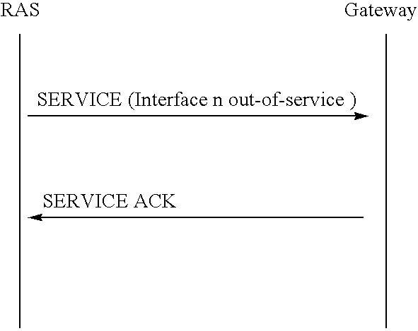
- the RAS sends this message to report to the gateway the change in status of a particular interface or a channel.
- This message is sent as an acknowledgment to the SERVICE message. If sent be the RAS, it indicates that the RAS is processing the SERVICE request. If sent by the gateway, it indicates that the gateway has recorded the change in status.
- the RAS sends this message to report to the gateway the result of continuity check for a particular channel.
- This message is sent by gateway to RAS as an acknowledgment to the CONTINUITY CHECK RESULT message.
- the following timing diagram shows that the RAS is responsible for the registration of the interfaces under its control.
- the following diagram shows successful Call establishment sequence for gateway originated calls.
- the following sequence illustrates when the gateway receives IAM message indicating that a continuity test should be performed on the circuit prior to the call establishment.
- the gateway sends SERVICE message to initiate the continuity check.
- the RAS performs continuity check and report the result using CONTINUITY CHECK RESULT.
- the RAS If the RAS detects that a particular T1/E1 line failed, it sends SERVICE message to the gateway. Established calls are torn down as part of normal processing—i.e the RAS modems detect loss of connection and the RAS disconnects the call.
- the gateway requests is blocking of CICs associated with the particular T1/E1.
- the RAS When the RAS loses IP connectivity, it tries to establish contact with the primary SS7 gateway; if that fails with the secondary gateway; if that fails with the primary gateway, etc. Once contact with a gateway is established, the RAS registers itself and the interfaces it supports.
Abstract
Description
-
- SS7 links are designed to carry signaling for large telecommunications switches, which handle many more terminations than a single remote access server. For example, a single 56 kilobits per second SS7 signaling link can support 50,000 busy hour call attempts.
- The SS7 network addressing scheme is also designed to handle a limited set of signaling points. The International Telecommunications Union (ITU) version of SS7 utilizes a 14 bit address field to identify all signaling points belonging to the international network, while the U.S. national version uses a 24 bit address field to identify signaling points belonging to North American networks.
- SS7 protocol layers come in a number of versions, including ITU and various national versions. It is appreciated that an SS7-Internet gateway supports these different versions as well.
-
- termination of SS7 protocols on the SS7 side, including Message Transfer Part (MTP) 305, ISDN User Part (ISUP) 310, Signaling Connection Control Part (SCCP) (not shown), and Transaction Capabilities (TCAP) (not shown) for database access traffic. Telephony User Part (TUP) may also be supported for some networks. This includes MTP network management functions as required for any SS7 signaling point.
- termination of IP and Local Area Network (LAN) protocols on the Internet or intranet side, including Transport Control Protocol/Internet Protocol (TCP/IP) 325, IEEE 802.3/Ethernet and other LAN protocols (not shown).
- for connection control, termination of the gateway-RAS protocol, herein referred to as the Open Access Signaling Protocol (OASP) 320. This maps between SS7 ISUP messages and connection setup to the RAS.
- mapping functions 315 providing for mapping of the Point Code and Circuit Identification Code (CIC) on the SS7 side to an IP address and Channel ID associated with the corresponding RAS device on the Internet side. This mapping is created during configuration of the gateway, and, in one embodiment, is a static mapping. More generic mapping of SS7 Point Codes and Subsystem Numbers to IP address and application information is necessary for database access features.
- support for gateway redundancy and security features, to ensure that the gateway reliability and security is consistent with signaling requirements.
-
- busying of trunks and channels;
- shutdown of trunks both gracefully and abruptly;
- the execution of circuit continuity check initiated by the far-end switch, either during call establishment or operator initiated; and
- the execution of circuit continuity check initiated by the SS7 gateway operator.
Mapping of Circuit Identification Codes (CICs)
-
- RAS STATUS
- RAS STATUS ACK
- INTERFACE STATUS
- INTERFACE STATUS ACK
- RESOURCE UPDATE
- RESOURCE UPDATE ACK
- SERVICE
- SERVICE ACK
- CONTINUITY CHECK RESULT
- CONTINUITY CHECK RESULT ACK
| Information | ||
| element | Direction | Length |
| Protocol | RAS −> |
1 |
| discriminator | ||
| Call reference | RAS −> GW | 3 |
| Message type | RAS −> |
1 |
| RAS Status Info | RAS −> GW | 3 |
| RAS Capabilities | RAS −> GW | 3–6 |
| Information | ||||
| element | Direction | Length | ||
| Protocol | GW −> |
1 | ||
| discriminator | ||||
| Call reference | GW −> RAS | 3 | ||
| Message type | GW −> |
1 | ||
| Cause | GW −> RAS | |||
| Information | ||||
| element | Direction | Length | ||
| Protocol | RAS −> |
1 | ||
| discriminator | ||||
| Call reference | RAS −> GW | 3 | ||
| Message type | RAS −> |
1 | ||
| Interface Status Info | RAS −> GW | |||
| Information | ||||
| element | Direction | Length | ||
| Protocol | GW −> |
1 | ||
| discriminator | ||||
| Call reference | GW −> RAS | 3 | ||
| Message type | GW −> |
1 | ||
| Cause | GW −> RAS | |||
| Information | ||||
| element | Direction | Length | ||
| Protocol | RAS −> |
1 | ||
| discriminator | ||||
| Call reference | RAS −> GW | 3 | ||
| Message type | RAS −> |
1 | ||
| Shift to Codeset | RAS −> |
1 | ||
| |
RAS −> GW | |||
| (see note 1) | ||||
| . . . | ||||
| RAS resource n | ||||
| (1) This information element can be repeated 1 to n times. | ||||
| Information | ||||
| element | Direction | Length | ||
| Protocol | GW −> |
1 | ||
| discriminator | ||||
| Call reference | GW −> RAS | 3 | ||
| Message type | GW −> |
1 | ||
| Cause | GW −> |
2–32 | ||
| Information | ||||
| element | Direction | Length | ||
| Protocol | Both | 1 | ||
| discriminator | ||||
| Call reference | Both | 3 | ||
| Message type | Both | 1 | ||
| Change Status | Both | 3 | ||
| Channel | Both | 3–6 | ||
| Identification | ||||
| Information | ||||
| element | Direction | Length | ||
| Protocol | Both | 1 | ||
| discriminator | ||||
| Call reference | Both | 3 | ||
| Message type | Both | 1 | ||
| Change Status | Both | 3 | ||
| Channel Identification | Both | 3–6 | ||
| Information | ||||
| element | Direction | Length | ||
| Protocol | RAS −> G/ |
1 | ||
| discriminator | ||||
| Call reference | RAS −> G/W | 3 | ||
| Message type | RAS −> G/ |
1 | ||
| Continuity Result | RAS −> G/W | |||
| Channel Identification | RAS −> G/W | 3–6 | ||
| Information | ||||
| element | Direction | Length | ||
| Protocol | G/W −> |
1 | ||
| discriminator | ||||
| Call reference | G/W −> RAS | 3 | ||
| Message type | G/W −> |
1 | ||


Claims (17)
Priority Applications (1)
| Application Number | Priority Date | Filing Date | Title |
|---|---|---|---|
| US09/246,578 US6990124B1 (en) | 1998-03-24 | 1999-02-08 | SS7-Internet gateway access signaling protocol |
Applications Claiming Priority (3)
| Application Number | Priority Date | Filing Date | Title |
|---|---|---|---|
| US7919098P | 1998-03-24 | 1998-03-24 | |
| US8819498P | 1998-06-05 | 1998-06-05 | |
| US09/246,578 US6990124B1 (en) | 1998-03-24 | 1999-02-08 | SS7-Internet gateway access signaling protocol |
Publications (1)
| Publication Number | Publication Date |
|---|---|
| US6990124B1 true US6990124B1 (en) | 2006-01-24 |
Family
ID=35614098
Family Applications (1)
| Application Number | Title | Priority Date | Filing Date |
|---|---|---|---|
| US09/246,578 Expired - Fee Related US6990124B1 (en) | 1998-03-24 | 1999-02-08 | SS7-Internet gateway access signaling protocol |
Country Status (1)
| Country | Link |
|---|---|
| US (1) | US6990124B1 (en) |
Cited By (13)
| Publication number | Priority date | Publication date | Assignee | Title |
|---|---|---|---|---|
| US20020186723A1 (en) * | 2001-06-05 | 2002-12-12 | Sprague David Michael | Methods and systems for communicating signaling information using a normalized signaling protocol |
| US20030086414A1 (en) * | 2001-09-26 | 2003-05-08 | Klaus Hoffmann | Service control for intelligent networks for packet network connections |
| US20030165135A1 (en) * | 2000-08-08 | 2003-09-04 | Ayal Itzkovitz | interface for intelligent network services |
| US20050207434A1 (en) * | 2004-03-18 | 2005-09-22 | Tekelec | Methods, systems, and computer program products for determining the application-level protocol of a signaling message |
| US20060229078A1 (en) * | 2005-01-21 | 2006-10-12 | Convergin | Service convergence across multiple communication domains |
| US20070094402A1 (en) * | 2005-10-17 | 2007-04-26 | Stevenson Harold R | Method, process and system for sharing data in a heterogeneous storage network |
| US20070263599A1 (en) * | 2006-05-15 | 2007-11-15 | Convergin Israel Ltd. | Delivering sip-based call services to circuit-switched terminals |
| US20080008193A1 (en) * | 2006-06-30 | 2008-01-10 | Hewlett-Packard Development Company, L.P. | Signalling system and method |
| US7454494B1 (en) * | 2003-01-07 | 2008-11-18 | Exfo Service Assurance Inc. | Apparatus and method for actively analyzing a data packet delivery path |
| US20090316693A1 (en) * | 2005-01-21 | 2009-12-24 | Convergin Israel Ltd | Convergence of Ancillary Call Services Across Multiple Communication Domains |
| US20100103837A1 (en) * | 2000-06-23 | 2010-04-29 | Jungck Peder J | Transparent provisioning of network access to an application |
| US20100303059A1 (en) * | 2009-05-27 | 2010-12-02 | Convergin Israel Ltd | Providing session-based service orchestration to event-based networks |
| US11916753B2 (en) | 2021-07-30 | 2024-02-27 | Ciena Corporation | Governance and interactions of autonomous pipeline-structured control applications |
Citations (10)
| Publication number | Priority date | Publication date | Assignee | Title |
|---|---|---|---|---|
| US5084816A (en) * | 1987-11-25 | 1992-01-28 | Bell Communications Research, Inc. | Real time fault tolerant transaction processing system |
| US5717745A (en) * | 1995-04-24 | 1998-02-10 | Mci Communications Corporation | System and method of efficiently evaluating different messages by a server in a telecommunications environment |
| US5870565A (en) * | 1996-05-06 | 1999-02-09 | Telefonaktiebolaget L M Ericsson (Publ) | Telecommunications management network connected to a common channel signaling network |
| US6064653A (en) * | 1997-01-07 | 2000-05-16 | Bell Atlantic Network Services, Inc. | Internetwork gateway to gateway alternative communication |
| US6070192A (en) * | 1997-05-30 | 2000-05-30 | Nortel Networks Corporation | Control in a data access transport service |
| US6078582A (en) * | 1996-12-18 | 2000-06-20 | Bell Atlantic Network Services, Inc. | Internet long distance telephone service |
| US6084956A (en) * | 1997-09-19 | 2000-07-04 | Nortel Networks Corporation | SS7 mediation for data network call setup and services interworking |
| US6134235A (en) * | 1997-10-08 | 2000-10-17 | At&T Corp. | Pots/packet bridge |
| US6292478B1 (en) * | 1996-11-21 | 2001-09-18 | Bell Atlantic Network Services, Inc. | Telecommunications system |
| US6292479B1 (en) * | 1997-03-19 | 2001-09-18 | Bell Atlantic Network Services, Inc. | Transport of caller identification information through diverse communication networks |
-
1999
- 1999-02-08 US US09/246,578 patent/US6990124B1/en not_active Expired - Fee Related
Patent Citations (10)
| Publication number | Priority date | Publication date | Assignee | Title |
|---|---|---|---|---|
| US5084816A (en) * | 1987-11-25 | 1992-01-28 | Bell Communications Research, Inc. | Real time fault tolerant transaction processing system |
| US5717745A (en) * | 1995-04-24 | 1998-02-10 | Mci Communications Corporation | System and method of efficiently evaluating different messages by a server in a telecommunications environment |
| US5870565A (en) * | 1996-05-06 | 1999-02-09 | Telefonaktiebolaget L M Ericsson (Publ) | Telecommunications management network connected to a common channel signaling network |
| US6292478B1 (en) * | 1996-11-21 | 2001-09-18 | Bell Atlantic Network Services, Inc. | Telecommunications system |
| US6078582A (en) * | 1996-12-18 | 2000-06-20 | Bell Atlantic Network Services, Inc. | Internet long distance telephone service |
| US6064653A (en) * | 1997-01-07 | 2000-05-16 | Bell Atlantic Network Services, Inc. | Internetwork gateway to gateway alternative communication |
| US6292479B1 (en) * | 1997-03-19 | 2001-09-18 | Bell Atlantic Network Services, Inc. | Transport of caller identification information through diverse communication networks |
| US6070192A (en) * | 1997-05-30 | 2000-05-30 | Nortel Networks Corporation | Control in a data access transport service |
| US6084956A (en) * | 1997-09-19 | 2000-07-04 | Nortel Networks Corporation | SS7 mediation for data network call setup and services interworking |
| US6134235A (en) * | 1997-10-08 | 2000-10-17 | At&T Corp. | Pots/packet bridge |
Non-Patent Citations (1)
| Title |
|---|
| Dr. Amir Atai and Dr. James Gordon, "Architectural Solutions to Internet Congestion Based on SS7 and Intelligent Network Capabilities, " A Bellcore White Paper, 1997, 18 pages. |
Cited By (30)
| Publication number | Priority date | Publication date | Assignee | Title |
|---|---|---|---|---|
| US20100103837A1 (en) * | 2000-06-23 | 2010-04-29 | Jungck Peder J | Transparent provisioning of network access to an application |
| US9444785B2 (en) * | 2000-06-23 | 2016-09-13 | Cloudshield Technologies, Inc. | Transparent provisioning of network access to an application |
| US20030165135A1 (en) * | 2000-08-08 | 2003-09-04 | Ayal Itzkovitz | interface for intelligent network services |
| US7496111B2 (en) * | 2000-08-08 | 2009-02-24 | Convergin Israel Ltd. | Interface for intelligent network services |
| US7295579B2 (en) * | 2001-06-05 | 2007-11-13 | Tekelec | Methods and systems for communicating signaling information using a normalized signaling protocol |
| US20020186723A1 (en) * | 2001-06-05 | 2002-12-12 | Sprague David Michael | Methods and systems for communicating signaling information using a normalized signaling protocol |
| US7248576B2 (en) * | 2001-09-26 | 2007-07-24 | Siemens Aktiengesellschaft | Service control for intelligent networks for packet network connections |
| US20030086414A1 (en) * | 2001-09-26 | 2003-05-08 | Klaus Hoffmann | Service control for intelligent networks for packet network connections |
| US7454494B1 (en) * | 2003-01-07 | 2008-11-18 | Exfo Service Assurance Inc. | Apparatus and method for actively analyzing a data packet delivery path |
| US7840670B2 (en) | 2003-01-07 | 2010-11-23 | Exfo Service Assurance, Inc. | Apparatus and method for passively analyzing a data packet delivery path |
| US20090086645A1 (en) * | 2003-01-07 | 2009-04-02 | Exfo Service Assurance, Inc. | Apparatus and method for passively analyzing a data packet delivery path |
| US20050207434A1 (en) * | 2004-03-18 | 2005-09-22 | Tekelec | Methods, systems, and computer program products for determining the application-level protocol of a signaling message |
| US7801124B2 (en) | 2004-03-18 | 2010-09-21 | Tekelec | Methods, systems, and computer program products for determining the application-level protocol of a signaling message |
| US20060276193A1 (en) * | 2005-01-21 | 2006-12-07 | Convergin Israel Ltd. | Service convergence across multiple communication domains |
| US20060234690A1 (en) * | 2005-01-21 | 2006-10-19 | Convergin | Management of multiple user identities in a communication system |
| US7865188B2 (en) | 2005-01-21 | 2011-01-04 | Oracle Israel Ltd. | Convergence of ancillary call services across multiple communication domains |
| US20060229078A1 (en) * | 2005-01-21 | 2006-10-12 | Convergin | Service convergence across multiple communication domains |
| US7620391B2 (en) | 2005-01-21 | 2009-11-17 | Convergin Israel Ltd. | Management of multiple user identities in a communication system |
| US20090316693A1 (en) * | 2005-01-21 | 2009-12-24 | Convergin Israel Ltd | Convergence of Ancillary Call Services Across Multiple Communication Domains |
| US20070094402A1 (en) * | 2005-10-17 | 2007-04-26 | Stevenson Harold R | Method, process and system for sharing data in a heterogeneous storage network |
| US8243715B2 (en) | 2006-05-15 | 2012-08-14 | Oracle Israel Ltd. | Delivering sip-based call services to circuit-switched terminals |
| US20070263599A1 (en) * | 2006-05-15 | 2007-11-15 | Convergin Israel Ltd. | Delivering sip-based call services to circuit-switched terminals |
| US20080008193A1 (en) * | 2006-06-30 | 2008-01-10 | Hewlett-Packard Development Company, L.P. | Signalling system and method |
| US20100303059A1 (en) * | 2009-05-27 | 2010-12-02 | Convergin Israel Ltd | Providing session-based service orchestration to event-based networks |
| US20100303066A1 (en) * | 2009-05-27 | 2010-12-02 | Convergin Israel Ltd | Providing session-based services to event-based networks in multi-leg calls |
| US20100303058A1 (en) * | 2009-05-27 | 2010-12-02 | Convergin Israel Ltd | Providing session-based services to event-based networks using partial information |
| US8493933B2 (en) | 2009-05-27 | 2013-07-23 | Oracle International Corporation | Providing session-based services to event-based networks using partial information |
| US8493913B2 (en) | 2009-05-27 | 2013-07-23 | Oracle International Corporation | Providing session-based service orchestration to event-based networks |
| US8848602B2 (en) | 2009-05-27 | 2014-09-30 | Oracle Israel Ltd. | Providing session-based services to event-based networks in multi-leg calls |
| US11916753B2 (en) | 2021-07-30 | 2024-02-27 | Ciena Corporation | Governance and interactions of autonomous pipeline-structured control applications |
Similar Documents
| Publication | Publication Date | Title |
|---|---|---|
| US6920144B2 (en) | Method, system and signaling gateways as an alternative to SS7 signal transfer points | |
| US6507649B1 (en) | Mechanism and method for distributing ISUP stacks over multiple loosely coupled processors | |
| US6324183B1 (en) | Systems and methods for communicating messages among signaling system 7 (SS7) signaling points (SPs) and internet protocol (IP) nodes using signal transfer points (STPS) | |
| US5933490A (en) | Overload protection for on-demand access to the internet that redirects calls from overloaded internet service provider (ISP) to alternate internet access provider | |
| US6333931B1 (en) | Method and apparatus for interconnecting a circuit-switched telephony network and a packet-switched data network, and applications thereof | |
| US7522580B2 (en) | Edge device and method for interconnecting SS7 signaling points (SPs) using edge device | |
| US6687251B1 (en) | Method and apparatus for distributed MTP Level 2 architecture | |
| US20030233612A1 (en) | Method for providing MTP-2 services in common channel communications | |
| US6990124B1 (en) | SS7-Internet gateway access signaling protocol | |
| US6282191B1 (en) | Methods and apparatus for transporting narrowband (voice) traffic over a broadband (ATM) network | |
| Kuhn et al. | Common channel signaling networks: Past, present, future | |
| Jabbari | Common channel signalling system number 7 for ISDN and intelligent networks | |
| Sidebottom et al. | Signaling system 7 (SS7) message transfer part 3 (MTP3)-user adaptation layer (M3UA) | |
| US5917901A (en) | Telecommunications system | |
| US20070140158A1 (en) | Method, apparatus and network arrangement for establishing calls in a communications network | |
| Cisco | Appendix A | |
| US20030231643A1 (en) | Signaling gateway for common channel communication through a packet switched network | |
| Chao | Emerging advanced intelligent network (AIN) for 21st century warfighters | |
| US20050195809A1 (en) | SS7 full duplex transverser | |
| WO2000079807A1 (en) | Signaling gateway | |
| Sidebottom et al. | RFC3332: Signaling System 7 (SS7) Message Transfer Part 3 (MTP3)-User Adaptation Layer (M3UA) | |
| CA2160467C (en) | Telecommunications system | |
| Donohoe et al. | Realization of a signaling system no. 7 network for AT&T | |
| Savadatti et al. | Overview of SS7 Protocol and Its Link Stability | |
| EP1816876B1 (en) | Method and apparatus for transferring signalling connection control part messages |
Legal Events
| Date | Code | Title | Description |
|---|---|---|---|
| AS | Assignment |
Owner name: BAY NETWORKS, INC., CALIFORNIA Free format text: ASSIGNMENT OF ASSIGNORS INTEREST;ASSIGNORS:DALIAS, ROBERT J.;ONG, LYNDON B.;MATOUSEK, JIRI;REEL/FRAME:009938/0088;SIGNING DATES FROM 19990319 TO 19990329 |
|
| AS | Assignment |
Owner name: NORTEL NETWORKS NA INC., CALIFORNIA Free format text: CHANGE OF NAME;ASSIGNOR:BAY NETWORKS, INC.;REEL/FRAME:010461/0283 Effective date: 19990430 |
|
| AS | Assignment |
Owner name: NORTEL NETWORKS CORPORATION, CANADA Free format text: ASSIGNMENT OF ASSIGNORS INTEREST;ASSIGNOR:NORTEL NETWORKS NA INC.;REEL/FRAME:010547/0891 Effective date: 19991229 |
|
| AS | Assignment |
Owner name: NORTEL NETWORKS LIMITED, CANADA Free format text: CHANGE OF NAME;ASSIGNOR:NORTEL NETWORKS CORPORATION;REEL/FRAME:011195/0706 Effective date: 20000830 Owner name: NORTEL NETWORKS LIMITED,CANADA Free format text: CHANGE OF NAME;ASSIGNOR:NORTEL NETWORKS CORPORATION;REEL/FRAME:011195/0706 Effective date: 20000830 |
|
| FEPP | Fee payment procedure |
Free format text: PAYOR NUMBER ASSIGNED (ORIGINAL EVENT CODE: ASPN); ENTITY STATUS OF PATENT OWNER: LARGE ENTITY |
|
| FPAY | Fee payment |
Year of fee payment: 4 |
|
| AS | Assignment |
Owner name: ROCKSTAR BIDCO, LP, NEW YORK Free format text: ASSIGNMENT OF ASSIGNORS INTEREST;ASSIGNOR:NORTEL NETWORKS LIMITED;REEL/FRAME:027164/0356 Effective date: 20110729 |
|
| FPAY | Fee payment |
Year of fee payment: 8 |
|
| AS | Assignment |
Owner name: ROCKSTAR CONSORTIUM US LP, TEXAS Free format text: ASSIGNMENT OF ASSIGNORS INTEREST;ASSIGNOR:ROCKSTAR BIDCO, LP;REEL/FRAME:032099/0853 Effective date: 20120509 |
|
| AS | Assignment |
Owner name: CONSTELLATION TECHNOLOGIES LLC, TEXAS Free format text: ASSIGNMENT OF ASSIGNORS INTEREST;ASSIGNOR:ROCKSTAR CONSORTIUM US LP;REEL/FRAME:032162/0524 Effective date: 20131113 |
|
| AS | Assignment |
Owner name: RPX CLEARINGHOUSE LLC, CALIFORNIA Free format text: ASSIGNMENT OF ASSIGNORS INTEREST;ASSIGNORS:ROCKSTAR CONSORTIUM US LP;ROCKSTAR CONSORTIUM LLC;BOCKSTAR TECHNOLOGIES LLC;AND OTHERS;REEL/FRAME:034924/0779 Effective date: 20150128 |
|
| AS | Assignment |
Owner name: JPMORGAN CHASE BANK, N.A., AS COLLATERAL AGENT, IL Free format text: SECURITY AGREEMENT;ASSIGNORS:RPX CORPORATION;RPX CLEARINGHOUSE LLC;REEL/FRAME:038041/0001 Effective date: 20160226 |
|
| FEPP | Fee payment procedure |
Free format text: MAINTENANCE FEE REMINDER MAILED (ORIGINAL EVENT CODE: REM.) |
|
| AS | Assignment |
Owner name: RPX CORPORATION, CALIFORNIA Free format text: RELEASE (REEL 038041 / FRAME 0001);ASSIGNOR:JPMORGAN CHASE BANK, N.A.;REEL/FRAME:044970/0030 Effective date: 20171222 Owner name: RPX CLEARINGHOUSE LLC, CALIFORNIA Free format text: RELEASE (REEL 038041 / FRAME 0001);ASSIGNOR:JPMORGAN CHASE BANK, N.A.;REEL/FRAME:044970/0030 Effective date: 20171222 |
|
| LAPS | Lapse for failure to pay maintenance fees |
Free format text: PATENT EXPIRED FOR FAILURE TO PAY MAINTENANCE FEES (ORIGINAL EVENT CODE: EXP.) |
|
| STCH | Information on status: patent discontinuation |
Free format text: PATENT EXPIRED DUE TO NONPAYMENT OF MAINTENANCE FEES UNDER 37 CFR 1.362 |
|
| FP | Lapsed due to failure to pay maintenance fee |
Effective date: 20180124 |