US6958205B2 - Image forming material and ammonium compound - Google Patents

Image forming material and ammonium compound Download PDF

Info

Publication number
US6958205B2
US6958205B2 US10/201,557 US20155702A US6958205B2 US 6958205 B2 US6958205 B2 US 6958205B2 US 20155702 A US20155702 A US 20155702A US 6958205 B2 US6958205 B2 US 6958205B2
Authority
US
United States
Prior art keywords
group
bond
carbon atom
ring
general formula
Prior art date
Legal status (The legal status is an assumption and is not a legal conclusion. Google has not performed a legal analysis and makes no representation as to the accuracy of the status listed.)
Expired - Lifetime, expires
Application number
US10/201,557
Other versions
US20030143481A1 (en
Inventor
Kaoru Iwato
Tadahiro Sorori
Current Assignee (The listed assignees may be inaccurate. Google has not performed a legal analysis and makes no representation or warranty as to the accuracy of the list.)
Fujifilm Holdings Corp
Fujifilm Corp
Original Assignee
Fuji Photo Film Co Ltd
Priority date (The priority date is an assumption and is not a legal conclusion. Google has not performed a legal analysis and makes no representation as to the accuracy of the date listed.)
Filing date
Publication date
Application filed by Fuji Photo Film Co Ltd filed Critical Fuji Photo Film Co Ltd
Assigned to FUJI PHOTO FILM CO., LTD. reassignment FUJI PHOTO FILM CO., LTD. ASSIGNMENT OF ASSIGNORS INTEREST (SEE DOCUMENT FOR DETAILS). Assignors: IWATO, KAORU, SORORI, TADAHIRO
Publication of US20030143481A1 publication Critical patent/US20030143481A1/en
Application granted granted Critical
Publication of US6958205B2 publication Critical patent/US6958205B2/en
Assigned to FUJIFILM CORPORATION reassignment FUJIFILM CORPORATION ASSIGNMENT OF ASSIGNORS INTEREST (SEE DOCUMENT FOR DETAILS). Assignors: FUJIFILM HOLDINGS CORPORATION (FORMERLY FUJI PHOTO FILM CO., LTD.)
Adjusted expiration legal-status Critical
Expired - Lifetime legal-status Critical Current

Links

Classifications

    • CCHEMISTRY; METALLURGY
    • C07ORGANIC CHEMISTRY
    • C07DHETEROCYCLIC COMPOUNDS
    • C07D217/00Heterocyclic compounds containing isoquinoline or hydrogenated isoquinoline ring systems
    • C07D217/02Heterocyclic compounds containing isoquinoline or hydrogenated isoquinoline ring systems with only hydrogen atoms or radicals containing only carbon and hydrogen atoms, directly attached to carbon atoms of the nitrogen-containing ring; Alkylene-bis-isoquinolines
    • C07D217/10Quaternary compounds
    • BPERFORMING OPERATIONS; TRANSPORTING
    • B41PRINTING; LINING MACHINES; TYPEWRITERS; STAMPS
    • B41CPROCESSES FOR THE MANUFACTURE OR REPRODUCTION OF PRINTING SURFACES
    • B41C1/00Forme preparation
    • B41C1/10Forme preparation for lithographic printing; Master sheets for transferring a lithographic image to the forme
    • B41C1/1008Forme preparation for lithographic printing; Master sheets for transferring a lithographic image to the forme by removal or destruction of lithographic material on the lithographic support, e.g. by laser or spark ablation; by the use of materials rendered soluble or insoluble by heat exposure, e.g. by heat produced from a light to heat transforming system; by on-the-press exposure or on-the-press development, e.g. by the fountain of photolithographic materials
    • CCHEMISTRY; METALLURGY
    • C07ORGANIC CHEMISTRY
    • C07DHETEROCYCLIC COMPOUNDS
    • C07D211/00Heterocyclic compounds containing hydrogenated pyridine rings, not condensed with other rings
    • C07D211/04Heterocyclic compounds containing hydrogenated pyridine rings, not condensed with other rings with only hydrogen or carbon atoms directly attached to the ring nitrogen atom
    • C07D211/06Heterocyclic compounds containing hydrogenated pyridine rings, not condensed with other rings with only hydrogen or carbon atoms directly attached to the ring nitrogen atom having no double bonds between ring members or between ring members and non-ring members
    • C07D211/36Heterocyclic compounds containing hydrogenated pyridine rings, not condensed with other rings with only hydrogen or carbon atoms directly attached to the ring nitrogen atom having no double bonds between ring members or between ring members and non-ring members with hetero atoms or with carbon atoms having three bonds to hetero atoms with at the most one bond to halogen, e.g. ester or nitrile radicals, directly attached to ring carbon atoms
    • C07D211/40Oxygen atoms
    • C07D211/42Oxygen atoms attached in position 3 or 5
    • CCHEMISTRY; METALLURGY
    • C07ORGANIC CHEMISTRY
    • C07DHETEROCYCLIC COMPOUNDS
    • C07D211/00Heterocyclic compounds containing hydrogenated pyridine rings, not condensed with other rings
    • C07D211/04Heterocyclic compounds containing hydrogenated pyridine rings, not condensed with other rings with only hydrogen or carbon atoms directly attached to the ring nitrogen atom
    • C07D211/06Heterocyclic compounds containing hydrogenated pyridine rings, not condensed with other rings with only hydrogen or carbon atoms directly attached to the ring nitrogen atom having no double bonds between ring members or between ring members and non-ring members
    • C07D211/36Heterocyclic compounds containing hydrogenated pyridine rings, not condensed with other rings with only hydrogen or carbon atoms directly attached to the ring nitrogen atom having no double bonds between ring members or between ring members and non-ring members with hetero atoms or with carbon atoms having three bonds to hetero atoms with at the most one bond to halogen, e.g. ester or nitrile radicals, directly attached to ring carbon atoms
    • C07D211/40Oxygen atoms
    • C07D211/44Oxygen atoms attached in position 4
    • C07D211/46Oxygen atoms attached in position 4 having a hydrogen atom as the second substituent in position 4
    • CCHEMISTRY; METALLURGY
    • C07ORGANIC CHEMISTRY
    • C07DHETEROCYCLIC COMPOUNDS
    • C07D295/00Heterocyclic compounds containing polymethylene-imine rings with at least five ring members, 3-azabicyclo [3.2.2] nonane, piperazine, morpholine or thiomorpholine rings, having only hydrogen atoms directly attached to the ring carbon atoms
    • C07D295/02Heterocyclic compounds containing polymethylene-imine rings with at least five ring members, 3-azabicyclo [3.2.2] nonane, piperazine, morpholine or thiomorpholine rings, having only hydrogen atoms directly attached to the ring carbon atoms containing only hydrogen and carbon atoms in addition to the ring hetero elements
    • C07D295/037Heterocyclic compounds containing polymethylene-imine rings with at least five ring members, 3-azabicyclo [3.2.2] nonane, piperazine, morpholine or thiomorpholine rings, having only hydrogen atoms directly attached to the ring carbon atoms containing only hydrogen and carbon atoms in addition to the ring hetero elements with quaternary ring nitrogen atoms
    • CCHEMISTRY; METALLURGY
    • C07ORGANIC CHEMISTRY
    • C07DHETEROCYCLIC COMPOUNDS
    • C07D295/00Heterocyclic compounds containing polymethylene-imine rings with at least five ring members, 3-azabicyclo [3.2.2] nonane, piperazine, morpholine or thiomorpholine rings, having only hydrogen atoms directly attached to the ring carbon atoms
    • C07D295/04Heterocyclic compounds containing polymethylene-imine rings with at least five ring members, 3-azabicyclo [3.2.2] nonane, piperazine, morpholine or thiomorpholine rings, having only hydrogen atoms directly attached to the ring carbon atoms with substituted hydrocarbon radicals attached to ring nitrogen atoms
    • C07D295/06Heterocyclic compounds containing polymethylene-imine rings with at least five ring members, 3-azabicyclo [3.2.2] nonane, piperazine, morpholine or thiomorpholine rings, having only hydrogen atoms directly attached to the ring carbon atoms with substituted hydrocarbon radicals attached to ring nitrogen atoms substituted by halogen atoms or nitro radicals
    • C07D295/073Heterocyclic compounds containing polymethylene-imine rings with at least five ring members, 3-azabicyclo [3.2.2] nonane, piperazine, morpholine or thiomorpholine rings, having only hydrogen atoms directly attached to the ring carbon atoms with substituted hydrocarbon radicals attached to ring nitrogen atoms substituted by halogen atoms or nitro radicals with the ring nitrogen atoms and the substituents separated by carbocyclic rings or by carbon chains interrupted by carbocyclic rings
    • CCHEMISTRY; METALLURGY
    • C07ORGANIC CHEMISTRY
    • C07DHETEROCYCLIC COMPOUNDS
    • C07D295/00Heterocyclic compounds containing polymethylene-imine rings with at least five ring members, 3-azabicyclo [3.2.2] nonane, piperazine, morpholine or thiomorpholine rings, having only hydrogen atoms directly attached to the ring carbon atoms
    • C07D295/04Heterocyclic compounds containing polymethylene-imine rings with at least five ring members, 3-azabicyclo [3.2.2] nonane, piperazine, morpholine or thiomorpholine rings, having only hydrogen atoms directly attached to the ring carbon atoms with substituted hydrocarbon radicals attached to ring nitrogen atoms
    • C07D295/08Heterocyclic compounds containing polymethylene-imine rings with at least five ring members, 3-azabicyclo [3.2.2] nonane, piperazine, morpholine or thiomorpholine rings, having only hydrogen atoms directly attached to the ring carbon atoms with substituted hydrocarbon radicals attached to ring nitrogen atoms substituted by singly bound oxygen or sulfur atoms
    • C07D295/096Heterocyclic compounds containing polymethylene-imine rings with at least five ring members, 3-azabicyclo [3.2.2] nonane, piperazine, morpholine or thiomorpholine rings, having only hydrogen atoms directly attached to the ring carbon atoms with substituted hydrocarbon radicals attached to ring nitrogen atoms substituted by singly bound oxygen or sulfur atoms with the ring nitrogen atoms and the oxygen or sulfur atoms separated by carbocyclic rings or by carbon chains interrupted by carbocyclic rings
    • CCHEMISTRY; METALLURGY
    • C07ORGANIC CHEMISTRY
    • C07DHETEROCYCLIC COMPOUNDS
    • C07D295/00Heterocyclic compounds containing polymethylene-imine rings with at least five ring members, 3-azabicyclo [3.2.2] nonane, piperazine, morpholine or thiomorpholine rings, having only hydrogen atoms directly attached to the ring carbon atoms
    • C07D295/04Heterocyclic compounds containing polymethylene-imine rings with at least five ring members, 3-azabicyclo [3.2.2] nonane, piperazine, morpholine or thiomorpholine rings, having only hydrogen atoms directly attached to the ring carbon atoms with substituted hydrocarbon radicals attached to ring nitrogen atoms
    • C07D295/10Heterocyclic compounds containing polymethylene-imine rings with at least five ring members, 3-azabicyclo [3.2.2] nonane, piperazine, morpholine or thiomorpholine rings, having only hydrogen atoms directly attached to the ring carbon atoms with substituted hydrocarbon radicals attached to ring nitrogen atoms substituted by doubly bound oxygen or sulphur atoms
    • C07D295/104Heterocyclic compounds containing polymethylene-imine rings with at least five ring members, 3-azabicyclo [3.2.2] nonane, piperazine, morpholine or thiomorpholine rings, having only hydrogen atoms directly attached to the ring carbon atoms with substituted hydrocarbon radicals attached to ring nitrogen atoms substituted by doubly bound oxygen or sulphur atoms with the ring nitrogen atoms and the doubly bound oxygen or sulfur atoms attached to the same carbon chain, which is not interrupted by carbocyclic rings
    • C07D295/108Heterocyclic compounds containing polymethylene-imine rings with at least five ring members, 3-azabicyclo [3.2.2] nonane, piperazine, morpholine or thiomorpholine rings, having only hydrogen atoms directly attached to the ring carbon atoms with substituted hydrocarbon radicals attached to ring nitrogen atoms substituted by doubly bound oxygen or sulphur atoms with the ring nitrogen atoms and the doubly bound oxygen or sulfur atoms attached to the same carbon chain, which is not interrupted by carbocyclic rings to an acyclic saturated chain
    • CCHEMISTRY; METALLURGY
    • C07ORGANIC CHEMISTRY
    • C07DHETEROCYCLIC COMPOUNDS
    • C07D295/00Heterocyclic compounds containing polymethylene-imine rings with at least five ring members, 3-azabicyclo [3.2.2] nonane, piperazine, morpholine or thiomorpholine rings, having only hydrogen atoms directly attached to the ring carbon atoms
    • C07D295/04Heterocyclic compounds containing polymethylene-imine rings with at least five ring members, 3-azabicyclo [3.2.2] nonane, piperazine, morpholine or thiomorpholine rings, having only hydrogen atoms directly attached to the ring carbon atoms with substituted hydrocarbon radicals attached to ring nitrogen atoms
    • C07D295/14Heterocyclic compounds containing polymethylene-imine rings with at least five ring members, 3-azabicyclo [3.2.2] nonane, piperazine, morpholine or thiomorpholine rings, having only hydrogen atoms directly attached to the ring carbon atoms with substituted hydrocarbon radicals attached to ring nitrogen atoms substituted by carbon atoms having three bonds to hetero atoms with at the most one bond to halogen, e.g. ester or nitrile radicals
    • C07D295/155Heterocyclic compounds containing polymethylene-imine rings with at least five ring members, 3-azabicyclo [3.2.2] nonane, piperazine, morpholine or thiomorpholine rings, having only hydrogen atoms directly attached to the ring carbon atoms with substituted hydrocarbon radicals attached to ring nitrogen atoms substituted by carbon atoms having three bonds to hetero atoms with at the most one bond to halogen, e.g. ester or nitrile radicals with the ring nitrogen atoms and the carbon atoms with three bonds to hetero atoms separated by carbocyclic rings or by carbon chains interrupted by carbocyclic rings
    • CCHEMISTRY; METALLURGY
    • C07ORGANIC CHEMISTRY
    • C07DHETEROCYCLIC COMPOUNDS
    • C07D295/00Heterocyclic compounds containing polymethylene-imine rings with at least five ring members, 3-azabicyclo [3.2.2] nonane, piperazine, morpholine or thiomorpholine rings, having only hydrogen atoms directly attached to the ring carbon atoms
    • C07D295/16Heterocyclic compounds containing polymethylene-imine rings with at least five ring members, 3-azabicyclo [3.2.2] nonane, piperazine, morpholine or thiomorpholine rings, having only hydrogen atoms directly attached to the ring carbon atoms acylated on ring nitrogen atoms
    • C07D295/18Heterocyclic compounds containing polymethylene-imine rings with at least five ring members, 3-azabicyclo [3.2.2] nonane, piperazine, morpholine or thiomorpholine rings, having only hydrogen atoms directly attached to the ring carbon atoms acylated on ring nitrogen atoms by radicals derived from carboxylic acids, or sulfur or nitrogen analogues thereof
    • C07D295/182Radicals derived from carboxylic acids
    • C07D295/192Radicals derived from carboxylic acids from aromatic carboxylic acids
    • CCHEMISTRY; METALLURGY
    • C07ORGANIC CHEMISTRY
    • C07DHETEROCYCLIC COMPOUNDS
    • C07D471/00Heterocyclic compounds containing nitrogen atoms as the only ring hetero atoms in the condensed system, at least one ring being a six-membered ring with one nitrogen atom, not provided for by groups C07D451/00 - C07D463/00
    • C07D471/02Heterocyclic compounds containing nitrogen atoms as the only ring hetero atoms in the condensed system, at least one ring being a six-membered ring with one nitrogen atom, not provided for by groups C07D451/00 - C07D463/00 in which the condensed system contains two hetero rings
    • C07D471/06Peri-condensed systems
    • CCHEMISTRY; METALLURGY
    • C07ORGANIC CHEMISTRY
    • C07DHETEROCYCLIC COMPOUNDS
    • C07D471/00Heterocyclic compounds containing nitrogen atoms as the only ring hetero atoms in the condensed system, at least one ring being a six-membered ring with one nitrogen atom, not provided for by groups C07D451/00 - C07D463/00
    • C07D471/02Heterocyclic compounds containing nitrogen atoms as the only ring hetero atoms in the condensed system, at least one ring being a six-membered ring with one nitrogen atom, not provided for by groups C07D451/00 - C07D463/00 in which the condensed system contains two hetero rings
    • C07D471/10Spiro-condensed systems
    • CCHEMISTRY; METALLURGY
    • C07ORGANIC CHEMISTRY
    • C07DHETEROCYCLIC COMPOUNDS
    • C07D487/00Heterocyclic compounds containing nitrogen atoms as the only ring hetero atoms in the condensed system, not provided for by groups C07D451/00 - C07D477/00
    • C07D487/02Heterocyclic compounds containing nitrogen atoms as the only ring hetero atoms in the condensed system, not provided for by groups C07D451/00 - C07D477/00 in which the condensed system contains two hetero rings
    • C07D487/10Spiro-condensed systems
    • BPERFORMING OPERATIONS; TRANSPORTING
    • B41PRINTING; LINING MACHINES; TYPEWRITERS; STAMPS
    • B41CPROCESSES FOR THE MANUFACTURE OR REPRODUCTION OF PRINTING SURFACES
    • B41C1/00Forme preparation
    • B41C1/10Forme preparation for lithographic printing; Master sheets for transferring a lithographic image to the forme
    • B41C1/1008Forme preparation for lithographic printing; Master sheets for transferring a lithographic image to the forme by removal or destruction of lithographic material on the lithographic support, e.g. by laser or spark ablation; by the use of materials rendered soluble or insoluble by heat exposure, e.g. by heat produced from a light to heat transforming system; by on-the-press exposure or on-the-press development, e.g. by the fountain of photolithographic materials
    • B41C1/1016Forme preparation for lithographic printing; Master sheets for transferring a lithographic image to the forme by removal or destruction of lithographic material on the lithographic support, e.g. by laser or spark ablation; by the use of materials rendered soluble or insoluble by heat exposure, e.g. by heat produced from a light to heat transforming system; by on-the-press exposure or on-the-press development, e.g. by the fountain of photolithographic materials characterised by structural details, e.g. protective layers, backcoat layers or several imaging layers
    • BPERFORMING OPERATIONS; TRANSPORTING
    • B41PRINTING; LINING MACHINES; TYPEWRITERS; STAMPS
    • B41CPROCESSES FOR THE MANUFACTURE OR REPRODUCTION OF PRINTING SURFACES
    • B41C2201/00Location, type or constituents of the non-imaging layers in lithographic printing formes
    • B41C2201/04Intermediate layers
    • BPERFORMING OPERATIONS; TRANSPORTING
    • B41PRINTING; LINING MACHINES; TYPEWRITERS; STAMPS
    • B41CPROCESSES FOR THE MANUFACTURE OR REPRODUCTION OF PRINTING SURFACES
    • B41C2201/00Location, type or constituents of the non-imaging layers in lithographic printing formes
    • B41C2201/14Location, type or constituents of the non-imaging layers in lithographic printing formes characterised by macromolecular organic compounds, e.g. binder, adhesives
    • BPERFORMING OPERATIONS; TRANSPORTING
    • B41PRINTING; LINING MACHINES; TYPEWRITERS; STAMPS
    • B41CPROCESSES FOR THE MANUFACTURE OR REPRODUCTION OF PRINTING SURFACES
    • B41C2210/00Preparation or type or constituents of the imaging layers, in relation to lithographic printing forme preparation
    • B41C2210/02Positive working, i.e. the exposed (imaged) areas are removed
    • BPERFORMING OPERATIONS; TRANSPORTING
    • B41PRINTING; LINING MACHINES; TYPEWRITERS; STAMPS
    • B41CPROCESSES FOR THE MANUFACTURE OR REPRODUCTION OF PRINTING SURFACES
    • B41C2210/00Preparation or type or constituents of the imaging layers, in relation to lithographic printing forme preparation
    • B41C2210/06Developable by an alkaline solution
    • BPERFORMING OPERATIONS; TRANSPORTING
    • B41PRINTING; LINING MACHINES; TYPEWRITERS; STAMPS
    • B41CPROCESSES FOR THE MANUFACTURE OR REPRODUCTION OF PRINTING SURFACES
    • B41C2210/00Preparation or type or constituents of the imaging layers, in relation to lithographic printing forme preparation
    • B41C2210/22Preparation or type or constituents of the imaging layers, in relation to lithographic printing forme preparation characterised by organic non-macromolecular additives, e.g. dyes, UV-absorbers, plasticisers
    • BPERFORMING OPERATIONS; TRANSPORTING
    • B41PRINTING; LINING MACHINES; TYPEWRITERS; STAMPS
    • B41CPROCESSES FOR THE MANUFACTURE OR REPRODUCTION OF PRINTING SURFACES
    • B41C2210/00Preparation or type or constituents of the imaging layers, in relation to lithographic printing forme preparation
    • B41C2210/24Preparation or type or constituents of the imaging layers, in relation to lithographic printing forme preparation characterised by a macromolecular compound or binder obtained by reactions involving carbon-to-carbon unsaturated bonds, e.g. acrylics, vinyl polymers
    • BPERFORMING OPERATIONS; TRANSPORTING
    • B41PRINTING; LINING MACHINES; TYPEWRITERS; STAMPS
    • B41CPROCESSES FOR THE MANUFACTURE OR REPRODUCTION OF PRINTING SURFACES
    • B41C2210/00Preparation or type or constituents of the imaging layers, in relation to lithographic printing forme preparation
    • B41C2210/26Preparation or type or constituents of the imaging layers, in relation to lithographic printing forme preparation characterised by a macromolecular compound or binder obtained by reactions not involving carbon-to-carbon unsaturated bonds
    • B41C2210/262Phenolic condensation polymers, e.g. novolacs, resols
    • YGENERAL TAGGING OF NEW TECHNOLOGICAL DEVELOPMENTS; GENERAL TAGGING OF CROSS-SECTIONAL TECHNOLOGIES SPANNING OVER SEVERAL SECTIONS OF THE IPC; TECHNICAL SUBJECTS COVERED BY FORMER USPC CROSS-REFERENCE ART COLLECTIONS [XRACs] AND DIGESTS
    • Y10TECHNICAL SUBJECTS COVERED BY FORMER USPC
    • Y10STECHNICAL SUBJECTS COVERED BY FORMER USPC CROSS-REFERENCE ART COLLECTIONS [XRACs] AND DIGESTS
    • Y10S430/00Radiation imagery chemistry: process, composition, or product thereof
    • Y10S430/165Thermal imaging composition

Definitions

  • the present invention relates to an image recording material usable as an offset printing master and a novel ammonium compound used for the recording material, and, particularly, to a positive image forming material useful as a positive planographic printing plate precursor for an infrared laser which planographic printing plate precursor is used for direct plate-making from digital signals from, especially, computers and also to a novel ammonium compound useful for improving the alkali resistance of the image forming material.
  • lasers are conspicuous and as, particularly, solid lasers/semiconductor lasers having an emission range from the near infrared region to the infrared region, high-output and small-sized lasers are becoming easily available. These lasers are very useful as exposure light sources when plate-making directly from digital data of computers and the like.
  • novolac resins are used as an aqueous alkali solution-soluble resin.
  • JP-A Japanese Patent Application Laid-Open
  • 7-285275 is a type in which a material which absorbs light to generate heat and a positive light-sensitive compound such as various onium salts and quinonediazide compounds are added to an aqueous alkali solution-soluble resin, such as a novolac resin, having a phenolic hydroxyl group, wherein the positive light-sensitive compound works as a dissolution inhibitor which substantially lowers the solubility of the aqueous alkali solution-soluble resin in image portions and does not eventually manifest the dissolution inhibitive function due to heat in non-image portions, so that the non-image portions are made removable by developing, thereby forming an image.
  • a positive light-sensitive compound such as various onium salts and quinonediazide compounds
  • the positive light-sensitive image forming materials described in WO97/39894 and EP0823327A2 comprise a material which absorbs light to generate heat and a rein which is changed in solubility in an aqueous alkali solution by heat, wherein these image forming materials have low solubility in an aqueous alkali solution in image portions and have increased solubility in an aqueous alkali solution by heat in non-image portions, so that the non-image portions are eventually removable by developing, whereby an image is formed.
  • a novolac resin is used particularly preferably from the reasons that there is a large difference in solubility to the developing solution between exposed portions and unexposed portions because it strongly interacts with a dissolution inhibitor and that the resin has high ink-accepting capability. And, with regard to the positive light-sensitive image forming materials for infrared lasers, a novolac resin is also used from the same reasons.
  • a heat mode positive image forming material in exposure using an infrared laser poses the problem that a difference in solubility to the developing solution (dissolution discrimination) between exposed portions and unexposed portions is insufficient and excess developing and developing inferiors are easily caused by variations in working conditions. Also in the case where the surface condition is slightly changed by touching the surface during handling, unexposed portions (image portions) dissolve in a developing solution to leave a scar-wise portion, causing deterioration in printing durability and print-adhesion inferior, leaving fears for affecting various performances such as processing stability, development latitudes and scratching resistance.
  • the inventors of the invention have made studies and as a result, found that the dissolution discrimination can be outstandingly improved by adding a compound represented by the following general formula (1).
  • the present invention was thus completed.
  • one aspect of the invention provides an image forming material comprising an image forming layer containing a water-insoluble and alkali-soluble resin, a light-heat converting agent and a compound represented by the following general formula (1): wherein R 1 to R 3 independently represent an organic group, where R 1 represents a residue forming a ring containing a N 1 atom, R 2 and R 3 may bond to each other to form a ring or at least one of R 2 and R 3 bonds to R 1 to form a ring and X ⁇ represents a conjugate base of an organic acid or inorganic acid.
  • the image forming material has a heat mode type image forming layer enabling the formation of an image by irradiation with an infrared laser.
  • an ammonium compound having such a ring as shown in the general formula (1) manifests strong dissolution inhibitive ability (inhibition) in an alkali-soluble resin due to an electrostatic interaction with the resin, also the N + atom is concealed sterically due to the ring because of its rigid skeleton during heat mode exposure, the mobility of the molecular side chain is limited, whereby the interaction between the ammonium compound and the binder which interaction has been once dissolved is formed again with difficulty and the inhibition is therefore dissolved efficiently, and eventually the result that the strength of the image portions (unexposed portions) and the excellent solubility of the non-image portions (exposed portions) in the alkali developing solution is made compatible, imparting a very large dissolution discrimination. Also, from this result, it is considered that improvements in development latitudes and scratching resistance are made in practice without lowering sensitivity. This makes it possible to form a high contrast image.
  • ammonium compounds represented by the following general formula (1-N) are novel compounds and used particularly preferably for the image forming material of the invention and improve the alkali resistance of the image forming material.
  • R N1 and R N2 independently represent a substituent selected from an alkyl group, an alkenyl group, an alkynyl group, an aryl group, an amino group, an alkoxy group, an aryloxy group, an acyl group, an alkoxycarbonyl group, an aryloxycarbonyl group, an acyloxy group, an acylamino group, an alkoxycarbonylamino group, an aryloxycarbonylamino group, a sulfonylamino group, a sulfamoyl group, a carbamoyl group, an alkylthio group, an arylthio group, a sulfonyl group, a hydroxyl group, a mercapto group
  • heat mode applicable in the invention means that it is possible to carry out recording by heat mode exposure.
  • the definition of the heat mode exposure in the invention will be described in detail.
  • a light-absorbing material e.g., dyes
  • One of these modes is a so-called photon mode in which the photo-excited light-absorbing material is deactivated by some photochemical interaction (e.g., energy transfer and electron transfer) with other reactive materials in the light-sensitive material, as a result the activated reactive materials cause the chemical or physical change required for the formation of an image.
  • Another is a so-called heat mode in which the photo-exited light-absorbing material generates heat to be deactivated and the reactive materials cause the chemical or physical change required for the formation of an image by utilizing the heat.
  • Exposure processes making use of the foregoing each mode are referred to as photon mode exposure and heat mode exposure.
  • a technological difference between the photon mode exposure and the heat mode exposure is based on whether or not the amount of energy of a few photons for exposure can be added up in calculating the amount of energy required for an intended reaction. For example, it is supposed to cause some reaction by using n photons. A photochemical interaction is utilized in the photon mode exposure. Therefore, each energy of photons cannot be added up because quantum energy and the law of conservation of momentum. Namely, in order to cause some reaction, the relation “amount of energy of one photon ⁇ amount of reaction energy” must be established.
  • the amount of energy can be added up because photo energy is converted into heat whose energy can be added up. Therefore, it is only required to establish the relation “amount of energy of n photons ⁇ amount of reaction energy”.
  • the adding-up of the amount of energy is restricted by heat diffusion. That is, if the next photo-excitation-deactivating process starts to generate heat until the heat is dissipated by heat diffusion from the presently focused exposed portion (reaction point), the heat is surely accumulated and added up, leading to a rise in temperature at the portion. However, when the next generation of heat is slow, the heat is dissipated and is not therefore accumulated.
  • the heat mode exposure there is a difference in the result between the case of applying a high energy amount of light for a short time and the case of applying a low energy amount of light for a long time.
  • the former case is more advantageous for the accumulation of heat.
  • the density of exposure power on the plate surface of the light-sensitive material must be 5000 w/cm 2 or more and preferably 10000 w/cm 2 or more.
  • ablation takes place when using a laser with a power density as high as 5.0 ⁇ 10 5 w/cm 2 or more, giving rise to the problems such as contamination of a light source and the use of such a laser is therefore undesirable.
  • the image forming material of the invention must comprise an ammonium compound having a ring represented by the general formula (1), an alkali-soluble resin and a light-heat converting agent in an image forming layer.
  • the components constituting the image forming layer will be hereinafter explained one by one.
  • R 1 to R 3 in the general formula (1) independently represent an organic group and R 1 represents a residue forming a ring containing a N 1 atom.
  • R 2 and R 3 may bond to each other to form a ring or at least one of R 2 and R 3 may bond to R 1 to form a ring.
  • X ⁇ represents a conjugate base of an organic acid or inorganic acid.
  • R 1 may be any group as far as it is a polyvalent organic group forming a ring containing a N 1 atom and may be not only a hydrocarbon type ring, but also a ring containing plural nitrogen atoms or other heteroatom such as an oxygen atom or a sulfur atom. Also, R 1 may be a ring having a double bond or those taking a polycyclic structure.
  • R 1 may include those in which the ring structure to be formed is a three-membered ring to a ten-membered ring. Those having a three-membered ring to an eight-membered ring are preferable in consideration of inhibition-dissolving ability, and those having a five-membered ring or a six-membered ring are preferable in consideration of synthetic aptitude.
  • the ring containing a N 1 atom may have a substituent.
  • substituents include an alkyl group, aryl group and halogen atom.
  • R 2 and R 3 may be optionally selected from whole organic groups, the both are preferably groups such as alkyl groups, aryl groups and the groups represented by the following general formula (2) wherein the sum of the numbers of carbon atoms of the both is 6 or more from the viewpoint of developing the inhibition, namely strong dissolution inhibitive ability. Further, at least one of them preferably has a branched or cyclic structure. Also, at least one of them preferably contains an aromatic ring and it is more preferable that both of R 2 and R 3 contain aromatic rings.
  • R 4 , R 5 and R 6 independently represent any optional substituent which can bond to each other to form a ring, may be the same of different or may form a double bond with the C 1 carbon atom, n denotes an integer of either 0 or 1 and m denotes an integer from 0 to 5, when plural R 6 s are present, they may be the same or different or may bond to each other to form a ring.
  • n 1, a structure in which at least either one of R 4 and R 5 is a hydrogen atom is preferable and a structure in which the both are hydrogen atoms is most preferable from the viewpoint of synthetic aptitude.
  • substituents represented by R 2 or R 3 may include alkyl groups (those having preferably 1 to 20 carbon atoms, more preferably 1 to 16 carbon atoms and particularly preferably 1 to 12 carbon atoms and specific examples include methyl, ethyl, n-butyl, isopropyl, tert-butyl, n-octyl, n-decyl, n-hexadecyl, cyclopropyl, cyclopentyl, cyclohexyl and 2-cyclohexylethyl), alkenyl groups (those having preferably 2 to 20 carbon atoms, more preferably 2 to 12 carbon atoms and particularly preferably 2 to 8 carbon atoms and specific examples include vinyl, allyl, 2-butenyl, 3-pentenyl and 2-cyclohexenylmethyl), alkynyl groups (those having preferably 2 to 20 carbon atoms, more preferably 2 to 12 carbon atoms and particularly preferably 2
  • substituents may be further substituted. Also, when two or more substituents are present, they may be the same or different. Also, they may bond to each other to form a ring if possible.
  • R 2 and R 3 are independently preferably an alkyl group, aryl group, alkenyl group, alkynyl group or groups obtained by optionally substituting these groups. Further, the sum of the numbers of carbon atoms of the both is preferably 6 or more, more preferably 8 or more and most preferably 10 or more from the view point of inhibition.
  • X ⁇ may be either a high molecular compound or low molecular compound or may be a polyvalent anion.
  • these anions may include anions corresponding to an organic acid conjugate base, such as R a1 —SO 3 ⁇ , R a1 —SO 2 ⁇ , R a1 —CO 2 ⁇ , R a1 —CS 2 ⁇ , R a1 —O—CS 2 ⁇ , R a1 —S—CS 2 ⁇ , R a1 —O—PO 2 ⁇ , (R a1 —O) 2 PO 2 ⁇ , R a1 (R a1 —O)PO 2 ⁇ , R a1 -EW 1 -Z ⁇ -EW 2 —R a1 , (R a1 ) 4 B ⁇ and Ar x O ⁇ or
  • R a1 s When plural R a1 s are present in the molecule, they may be selected independently or may bond to each other to form a ring, EW 1 and EW 2 independently represent an electron attractive group and specific examples thereof may include —SO—, —CO—, —SO 2 — and —CN—, Z represents —CR z1 — or —N— (R z1 represents a hydrogen atom or a substituent) and Ar x represents an aryl group.
  • Preferable examples of of the compounds represented by the general formula (1) may include compounds represented by the general formula (1-a).
  • R 2 , R 3 and X ⁇ respectively have the same meaning as those explained in the general formula (1) and also have the same preferable examples.
  • R 2 and R 3 independently represent more preferably an alkyl group, an aryl group, an alkenyl group, an alkynyl group or groups obtained by optionally substituting these groups and further, the sum of the numbers of carbon atoms of the both is preferably 6 or more, more preferably 8 or more and most preferably 10 or more from the viewpoint of the inhibition.
  • R 4 to R 7 independently represent a hydrogen atom or a substituent.
  • the substituents given as the examples of R 2 and R 3 in the general formula (1) may be used.
  • R 4 to R 7 may be the same or different, may bond to each other to form a ring or may bond to L 1 , R 2 and/or R 3 to form a ring.
  • R 4 to R 7 may not be present corresponding to this.
  • L 1 represents a polyvalent connecting group forming a ring containing —C 1 —N 1 —C 2 — or a single bond.
  • the ring composed of L 1 , C 1 , N 1 and C 2 is preferably a three-membered ring to an ten-membered ring.
  • the ring is more preferably a three-membered ring to a eight-membered ring from the viewpoint of inhibition-dissolving ability and more preferably a five-membered ring and a six-membered ring from the viewpoint of synthetic aptitude.
  • R 4 to R 7 bond to the same atom
  • R 2 , R 3 and X ⁇ respectively have the same meaning as those in the general formula (1) and each preferable examples are also the same.
  • R 4 to R 11 independently represent a hydrogen atom or a substituent.
  • the substituents given as the examples of R 2 and R 3 in the general formula (1) may be used.
  • R 4 to R 11 may be the same or different, may bond to each other to form a ring or may bond to L 2 , R 2 and/or R 3 to form a ring.
  • R 4 to R 11 may not be present corresponding to this.
  • L 2 represents a polyvalent connecting group forming a ring containing —C 3 —C 1 —N 1 —C 2 —C 4 — and a single bond or a double bond connecting C 3 with C 4 .
  • Preferable examples of L 2 may include those in which the ring to be formed is a five-membered ring to a ten-membered ring. Those having a five-membered ring to an eight-membered ring are preferable from the viewpoint of the inhibition-dissolving ability and those having a five-membered ring or a six-membered ring are preferable in the viewpoint of synthetic aptitude.
  • R 2 and X ⁇ respectively have the same meaning as those in the general formula (1) and each preferable range is also the same.
  • R 2 is more preferably an alkyl group, an aryl group, an alkenyl group, an alkynyl group or groups obtained by optionally substituting these groups.
  • the number of carbons of R 2 is preferably 2 or more, more preferably 3 or more and particularly preferably 4 or more from the viewpoint of the inhibition.
  • R 4 to R 13 independently represent a hydrogen atom or a substituent.
  • the substituents given as the examples of R 2 and R 3 in the general formula (1) may be used.
  • R 4 to R 13 may be the same or different, may bond to each other to form a ring or may bond to L 2 , R 2 and/or R 3 to form a ring.
  • R 4 to R 11 may not be present corresponding to this.
  • Ar 1 represents an aromatic cyclic group and substituted or unsubstituted phenyl, naphthyl, anthranyl, phenanthrenyl, pyridyl, pyrazyl, imidazolyl, quinolinyl, indolyl, isoquinolinyl, pyrrolyl, furanyl, pyrazolyl, triazolyl, tetrazolyl, oxazolyl, oxadiazolyl, thiazolyl and pyrimidinyl may be used.
  • Ar 1 may bond to L 2 , R 2 and R 4 to R 13 to form a ring.
  • n denotes an integer of 0 or a positive integer and is preferably 0, 1, 2 or 3, more preferably 0, 1 or 2 and particularly preferably 0 or 1.
  • Plural R 12 s and R 13 s are present inevitably when n is 2 or more and plural R 12 s and R 13 s may be respectively the same or different or may independently bond to each other to form a ring.
  • L 2 represents a polyvalent connecting group forming a ring containing —C 3 —C 1 —N 1 —C 2 —C 4 — and a single bond or a double bond connecting C 3 with C 4 .
  • Preferable examples of L 2 may include those in which the ring to be formed is a five-membered ring to a ten-membered ring. Those having a five-membered ring to an eight-membered ring are preferable from the viewpoint of the inhibition-dissolving ability and those-having a five-membered ring or a six-membered ring are preferable in the viewpoint of synthetic aptitude.
  • R 2 and X ⁇ respectively have the same meaning as those in the general formula (1) and each preferable range is also the same.
  • R 2 is more preferably an alkyl group, an aryl group, an alkenyl group, an alkynyl group or groups obtained by optionally substituting these groups.
  • the number of carbons of R 2 is preferably 2 or more, more preferably 3 or more and particularly preferably 4 or more from the viewpoint of the inhibition.
  • R 4 to R 14 independently represent a hydrogen atom or a substituent.
  • the substituents given as the examples of R 2 and R 3 in the general formula (1) may be used.
  • R 4 to R 14 may be the same or different, may bond to each other to form a ring or may bond to L 2 , R 2 and/or R 3 to form a ring.
  • R 4 to R 11 may not be present corresponding to this.
  • n denotes an integer from 0 to 5.
  • Plural R 14 s are present when m is 2 or more and plural R 14 s may be the same or different or may bond to each other to form a ring.
  • n denotes an integer of 0 or a positive integer and is preferably 0, 1, 2 or 3, more preferably 0, 1 or 2 and particularly preferably 0 or 1.
  • Plural R 12 s and R 13 s are present inevitably when n is 2 or more and plural R 12 s and R 13 s may be respectively the same or different or may independently bond to each other to form a ring.
  • L 2 represents a polyvalent connecting group forming a ring containing —C 3 —C 1 —N 1 —C 2 —C 4 — and a single bond or a double bond connecting C 3 with C 4 .
  • Preferable examples of L 2 may include those in which the ring to be formed is a five-membered ring to a ten-membered ring. Those having a five-membered ring to an eight-membered ring are preferable from the viewpoint of the inhibition-dissolving ability and those having a five-membered ring or a six-membered ring are preferable in the view of synthetic aptitude.
  • the compounds represented by the general formula (1-e) may be given.
  • R 2 and X ⁇ respectively have the same meaning as those in the general formula (1) and each preferable range is also the same.
  • R 2 is more preferably an alkyl group, an aryl group, an alkenyl group, an alkynyl group or groups obtained by optionally substituting these groups. Further, the number of carbons of R 2 is preferably 2 or more, more preferably 3 or more and particularly preferably 4 or more from the viewpoint of the inhibition.
  • R 4 to R 14 independently represent a hydrogen atom or a substituent.
  • the substituents given as the examples of R 2 and R 3 in the general formula (1) may be used.
  • R 4 to R 14 may be the same or different, may bond to each other to form a ring or may bond to L 3 and/or R 2 to form a ring.
  • R 4 to R 11 may not be present corresponding to this.
  • n denotes an integer from 0 to 5.
  • Plural R 14 s are present when m is 2 or more and plural R 14 s may be the same or different or may bond to each other to form a ring.
  • n denotes an integer of 0 or a positive integer and is preferably 0, 1, 2 or 3, more preferably 0, 1 or 2 and particularly preferably 0 or 1.
  • Plural R 12 s and R 13 s are present inevitably when n is 2 or more and plural R 12 s and R 13 s may be respectively the same or different or may independently bond to each other to form a ring.
  • L 3 represents a single bond or a double bond connecting C 3 with C 4 and a polyvalent connecting group forming a ring containing —C 3 —C 1 —N 1 —C 2 —C 4 —.
  • the connecting group —O—, —S—, —N(R L1 )— or —C(R L2 )(R L3 )— may be used.
  • R L1 to R L3 may independently represent a hydrogen atom or the substituents given as examples of R 2 and R 3 in the general formula (1) or may bond to R 2 and/or R 4 to R 14 to form a ring structure.
  • R 16 and R 17 may be the same or different or may bond to each other to form a ring.
  • R L1 to R L3 may not be present.
  • R 4 to R 14 and among R L1 to R L3 bond to the same atom
  • R 4 to R 14 and among R L1 to R L3 bond to the adjacent two atoms
  • the compounds represented by the general formula (1-f) may be given.
  • X ⁇ respectively has the same meaning as that in the general formula (1) and its preferable range is also the same.
  • R 4 to R 17 independently represent a hydrogen atom or a substituent.
  • the substituents given as the examples of R 2 and R 3 in the general formula (1) may be used.
  • R 4 to R 17 may be the same or different, may bond to each other to form a ring or may bond to L 3 , R 2 and/or R 3 to form a ring.
  • R 4 to R 11 may not be present corresponding to this.
  • n 1 and m 2 independently denote an integer from 0 to 5.
  • Plural R 14 s and R 17 s are present when m 1 and m 2 are independently 2 or more and plural R 14 s and R 17 s may be respectively the same or different or may independently bond to each other to form a ring.
  • n 1 and n 2 independently denote an integer of 0 or a positive integer and are preferably 0, 1, 2 or 3, more preferably 0, 1 or 2 and particularly preferably 0 or 1.
  • Plural R 12 s, R 13 s, R 15 s and R 16 s are present inevitably when n 1 and n 2 are independently 2 or more and plural R 12 s, R 13 s, R 15 s and R 16 s may be respectively the same or different or may independently bond to each other to form a ring.
  • L 3 represents a single bond or a double bond connecting C 3 with C 4 and a polyvalent connecting group forming a ring containing —C 3 —C 1 —N 1 —C 2 —C 4 —.
  • the connecting group —O—, —S—, —N(R L1 )— or —C(R L2 )(R L3 )— may be used.
  • R L1 to R L3 may independently represent a hydrogen atom or the substituents given as examples of R 2 and R 3 in the general formula (1) or may bond to R 2 and/or R 4 to R 14 to form a ring.
  • R 16 and R 17 may be the same or different and may bond to each other to form a ring.
  • R L1 to R L3 may not be present.
  • R 4 to R 17 and among R L1 to R L3 bond to the same atom
  • R 4 to R 17 and among R L1 to R L3 bond to the adjacent two atoms
  • the compounds represented by the compounds No. I-1 to I-61 are examples in which the ring containing a N atom is six-membered ring
  • the compounds represented by the compounds No. II-1 to II-17 are examples in which the ring containing a N atom is five-membered ring
  • the compounds represented by the compounds No. III-1 to III-17 are examples in which the ring containing a N atom is six-membered ring having a methyl group as a substituent
  • the compounds represented by the compounds No. IV-1 to IV-17 are examples in which the ring containing a N atom and an O atom is six-membered ring.
  • the following various compound represented by the compounds No. V.1 to V.22 are preferably used as the compounds represented by the general formula (1) which can produce the effect of the invention.
  • compounds represented by the general formula (1) compounds having a structure in which the ring containing N 1 atom is a six-membered alicyclic ring (piperidine ring) and which has an aromatic ring connected directly to the N 1 atom and an aromatic ring bonded to the N 1 atom via CH 2 , namely the ammonium compounds represented by the following general formula (1-N) are novel compounds and may be preferably used for the image forming material of the invention.
  • R N1 and R N2 independently represent a substituent selected from an alkyl group, alkenyl group, alkynyl group, aryl group, amino group, alkoxy group, aryloxy group, acyl group, alkoxycarbonyl group, aryloxycarbonyl group, acyloxy group, acylamino group, alkoxycarbonylamino group, aryloxycarbonylamino group, sulfonylamino group, sulfamoyl group, carbamoyl group, alkylthio group, arylthio group, sulfonyl group, hydroxyl group, mercapto group, halogen atom, cyano group, sulfo group, carboxyl group and nitro group and m and n independently denote an integer from 0 to 5.
  • R N1 s and R N2 s When plural R N1 s and R N2 s are respectively present, plural R N1 s and R N2 s may be respectively the same or different and may independently bond to each other to form a ring.
  • R N1 and R N2 may be cyclic compounds, straight-chain compounds or compounds having a branched chain. These compounds may have a substituent selected from the same group.
  • Y represents —CH 2 —, —O— or —S—.
  • X ⁇ may be anions corresponding to an organic acid conjugate base, such as R a1 —SO 3 ⁇ , R a1 —SO 2 ⁇ , R a1 —CO 2 ⁇ , R a1 —O—PO 2 ⁇ , (R a1 —O) 2 PO 2 ⁇ , R a1 (R a1 —O)PO 2 ⁇ , R a1 -EW 1 -Z ⁇ -EW 2 -R a1 , (R a1 ) 4 B ⁇ and Ar x O ⁇ or anions corresponding to an inorganic acid conjugate base, such as F ⁇ , Cl ⁇ , Br ⁇ , I ⁇ , PF 6 ⁇ , BF 4 ⁇ , SbF 6 ⁇ , ClO 4 ⁇ , SCN ⁇ , CN ⁇ , SiF 6 ⁇ and FSO 3 ⁇ , wherein R a1 is an organic substituent and represents
  • R a1 s When plural R a1 s are present in the molecule, they may be selected independently or may bond to each other to form a ring, EW 1 and EW 2 independently represent an electron attractive group and specific examples of these groups may include —SO—, —CO—, —SO 2 —, —CN—, —NO 2 and —CF 3 .
  • Z represents —CR z1 — or —N— (R z1 represents a hydrogen atom or a substituent).
  • Ar x represents a substituted or unsubstituted aryl group.
  • novel ammonium compound having such a structure examples include the compounds (I-2) to (I-4), (I-6) to (I-11), (I-39), (I-41), (I-45), (I-51), (I-53), (I-59), (IV-3), (IV-9), (IV-12), (IV-15), (IV-16) and (V-6) among the compounds exemplified above.
  • a reaction container was charged with 1,5-dibromopentane (43 g, 186.6 mmol), sodium carbonate (30 g, 280 mmol) and 100 ml of methanol which were weighed and the mixture was stirred at ambient temperature. Then, p-toluidine (10 g, 93.3 mmol) was dissolved in methanol (50 ml) and the solution was added dropwise to the reaction solution. The reaction solution was heated to 55° C. and stirred for 5 hours. The reaction solution was filtered and the resulting filtrate was concentrated under a reduced pressure.
  • a reaction container was charged with 1-(4-methylphenyl)piperidine (4.0 g, 22.8 mmol) and 10 ml of acetone and the mixture was stirred at ambient temperature. Then, ⁇ -bromo-p-xylene (5 g, 27.4 mmol) was added to the reaction solution. The reaction solution was stirred for 3 hours and 20 ml of ethyl acetate was added to the solution. The reaction mixture was further stirred for 30 minutes and subjected to suction filtration to collect a white powder. The resulting powder was dried to obtain 4-methylbenzyl(4-methylphenyl)piperidiniumbromide (6.8 g, yield: 83%).
  • An aqueous solution prepared by dissolving 4-methylphenylbenzylpiperidinium bromide (13.85 g, 0.04 mmol) in 20 ml of deionized water was mixed with an aqueous solution prepared by dissolving potassium hexafluorophosphate (KPF 6 , 8.83 g, 0.048 mmol) in 30 ml of deionized water and the produced white solid was collected by filtration. The resulting white solid was washed with 300 ml of deionized water, subjected to filtration and dried to obtain 4-methylphenylbenzylpiperidinium hexafluorophosphate (15.6 g, yield: 95%).
  • KPF 6 potassium hexafluorophosphate
  • the compounds represented by the general formula (1) to be used in the image forming material of the invention may be used either singly or in combinations of two or more.
  • the content of the compound is preferably 50% or less from the viewpoint of film forming ability, preferably in a range from 0.1% to 30% with the view of obtaining significantly good image forming ability and most preferably in a range from 0.5% to 15% as the amount enabling the compatibility between printing qualities such as printing durability and image forming characteristics at a higher level.
  • the water-insoluble and alkali-soluble resin (hereinafter, referred to as an alkali soluble resin as the case may be) to be used for the positive image forming layer according to the invention include homopolymers and copolymers containing an acidic group on the primary chain and/or the side chain in a polymer and mixtures of these polymers.
  • those containing the acidic groups given in the following (1) to (6) on the primary chain and/or the side chain thereof are preferable in view of solubility in an alkaline developing solution and the manifestation of dissolution inhibitive ability.
  • Ar represents a divalent aryl connecting group which may have a substituent and R represents a hydrocarbon group which may have a substituent.
  • alkali-soluble resins having an acidic group selected from the (1) to (6) alkali-soluble resins having (1) a phenol group, (2) a sulfonamide group and/or (3) an active imide group are preferable and, particularly, alkali-soluble resins having (1) a phenol group or (2) a sulfonamide group are most preferable with the view of securing solubility in an alkaline developer, development latitudes and film strength sufficiently.
  • alkali-soluble resins having an acidic group selected from the (1) to (6) the following compounds may be exemplified.
  • Examples of the compound having a phenol group may include acrylamides, methacrylamides, acrylates, methacrylates having a phenol group or hydroxystyrene.
  • m-aminosulfonylphenyl methacrylate particularly m-aminosulfonylphenyl methacrylate, N-(p-aminosulfonylphenyl)methacrylamide, N-(p-aminosulfonylphenyl) acrylamide and the like may be preferably used for the positive planographic printing plate of the invention.
  • N-(p-toluenesulfonyl)methacrylamide, N-(p-toluenesulfonyl)acrylamide and the like may be preferably used.
  • the minimum structural unit having an acidic group selected from the foregoing (1) to (6), which unit constitutes the alkali-soluble resin to be used in the positive image forming layer is not limited to only one type and alkali-soluble resins obtained by copolymerizing two or more minimum structural units having either the same acidic groups or different acidic groups may be used.
  • the copolymer is those containing the compound which has an acidic group selected from the above (1) to (6) and is to be polymerized in an amount of preferably 10 mol % or more and more preferably 20 mol % or more in the copolymer.
  • amount is less than 10 mol %, there is a tendency that the developing latitude is insufficiently improved.
  • a compound which does not contain the acidic group of the above (1) to (6) may also be used.
  • the compound which does not contain the acidic group of the above (1) to (6) may include the compounds described in the following (m1) to (m12). These compounds, however, are not intended to be limiting of the invention.
  • the alkali-soluble resin having a phenolic hydroxyl group is preferable in view of excellent image-forming ability in exposure using an infrared laser or the like.
  • novolac resins such as phenol-formaldehyde resins, m-cresol-formaldehyde resins, p-cresol-formaldehyde resins, m-/p-mixed cresol-formaldehyde resins and phenol/cresol (may be any of m-, p- or a mixture of m-/p-)-formaldehyde resins and pyrogallol-acetone resins are more preferable.
  • alkali-soluble resin having a phenolic hydroxyl group condensates of phenols containing an alkyl group having 3 to 8 carbon atoms as a substituent and formaldehyde, such as t-butylphenol-formaldehyde resins and octylphenol-formaldehyde resins as described in the specification of U.S. Pat. No. 4,123,279.
  • the alkali-soluble resin has a weight average molecular weight of 500 or more and more preferably 1,000 to 700,000 in view of image forming ability. Also, its number average molecular weight is preferably 500 or more and more preferably 750 to 650,000.
  • the degree of dispersion (weight average molecular weight/number average molecular weight) of the alkali-soluble resin is preferably 1.1 to 10.
  • these alkali-soluble resins may be used either singly or in combinations of two or more.
  • condensates of phenols having an alkyl group having 3 to 8 carbon atoms as a substituent and formaldehyde such as condensates of t-butylphenol and formaldehyde and condensates of octylphenol and formaldehyde as described in the specification of U.S. Pat. No. 4,123,279
  • the alkali-soluble resin having a phenol structure having an electron attractive group on an aromatic ring as described in JP-A No. 2000-241972 submitted previously by the inventors of the invention may be used together.
  • the total content of the alkali-soluble resin in the invention is preferably 30 to 98% by weight and more preferably 40 to 95% by weight based on the total solid of the image forming layer.
  • the content is less than 30% by weight, the durability tends to be impaired whereas when the content exceeds 98% by weight, the sensitivity and the image formability tend to be reduced.
  • any material may be used without any limitation to the absorption wavelength range as far as it is a material which absorbs the light-energy radiation used for recording to generate heat.
  • infrared-absorbable dyes and pigments having an absorption maximum in a wavelength range from 760 nm to 1200 nm are preferable from the viewpoint of adaptability to an easily available high-output laser.
  • dyes commercially available dyes and, for example known dyes described in literature such as “Dye Handbook” (edited by Organic Synthetic Chemical Association, published in 1970) may be utilized. Specific examples of these dyes may include azo dyes, metal complex azo dyes, pyrazolone azo dyes, naphthoquinone dyes, anthraquinone dyes, phthalocyanine dyes, carbonium dyes, quinoneimide dyes, methine dyes, cyanine dyes, squalilium dyes, pyrylium salts, metal thiolate complexes, oxonol dyes, diimmonium dyes, aminium dyes and croconium dyes.
  • the dye may include cyanine dyes described in JP-A Nos. 58-125246, 59-84356, 59-202829, 60-78787 and the like and methine dyes described in JP-A Nos. 58-173696, 58-181690, 58-194595 and the like, naphthoquinone dyes described in JP-A Nos. 58-112793, 58-224793, 59-48187, 59-73996, 60-52940, 60-63744 and the like, squalilium dyes described in JP-A No. 58-112792 and the like and cyanine dyes described in U.K. patent No. 434,875.
  • Near-infrared absorbing sensitizer described in U.S. Pat. No. 5,156,938 are also preferably used.
  • the dye may include near-infrared absorbing dyes represented by the formulae (I) or (II) described in the specification of U.S. Pat. No. 4,756,993.
  • dyes represented by the following formulae (a) to (e) are preferable because these dyes have superior light-heat conversion efficiency.
  • cyanine dyes represented by the following general formula (a) are most preferable because these dyes impart high polymerization activity when used in the polymerizable composition according to the invention and have high stability and profitability.
  • X 1 represents a hydrogen atom, a halogen atom, —NPh 2 , X 2 -L 1 or a group shown below.
  • X 2 represents an oxygen atom or a sulfur atom
  • L 1 represents a hydrocarbon group having 1 to 12 carbon atoms, an aromatic ring having a heteroatom or a hydrocarbon group containing a heteroatom and having 1 to 12 carbon atoms.
  • the heteroatom represents N, S, O, a halogen atom or Se.
  • R 1 and R 2 independently represent a hydrocarbon group having 1 to 12 carbon atoms.
  • R 1 and R 2 are independently preferably a hydrocarbon group having 2 or more carbon atoms in view of the preservation stability of a light-sensitive layer coating solution and, moreover, R 1 and R 2 particularly preferably bond to each other to form a five-membered or six-membered ring.
  • Ar 1 and Ar 2 which may be the same or different, independently represent an aromatic hydrocarbon group which may have a substituent.
  • the aromatic hydrocarbon group include a benzene ring or naphthalene ring.
  • the substituent include hydrocarbon groups having 12 or less carbon atoms, halogen atoms and alkoxy groups having 12 or less carbon atoms.
  • Y 1 and Y 2 which may be the same or different, independently represent a sulfur atom or a dialkylmethylene group having 12 or less carbon atoms.
  • R 3 and R 4 which may be the same or different, independently represent a hydrocarbon group which may have a substituent and has 20 or less carbon atoms.
  • R 5 , R 6 , R 7 and R 8 which may be the same or different, independently represent a hydrogen atom or a hydrocarbon group having 12 or less carbon atoms.
  • a hydrogen atom is preferable from the viewpoint of the availability of raw materials.
  • Za ⁇ represents a counter anion. In the case where any one of R 1 to R 8 is substituted with a sulfo group, Za + is not required.
  • Za ⁇ is preferably halogen ions, perchloric acid ions, tetrafluoroborate ions, hexafluorophosphate ions and sulfonic acid ions and particularly preferably perchloric acid ions, hexafluorophosphate ions and arylsulfonic acid ions in view of the preservation stability of a light-sensitive layer coating solution.
  • cyanine dyes which are represented by the general formula (a) and preferably used may include those described in the specification of Japanese Patent Application No. 11-310623, paragraphs No. [0017] to No. [0019], the specification of Japanese Patent Application No. 2000-224031, paragraphs No. [0012] to No. [0038] and the specification of Japanese Patent Application No. 2000-211147, paragraphs No. [0012] to No. [0023], besides dyes exemplified below.
  • L represents a methine chain having 7 or more conjugate carbon atoms.
  • the methine chain may have a substituent and the substituents may bond to each other to form a ring.
  • Zb + represents a counter cation.
  • the counter cation include ammonium, iodonium, sulfonium, phosphonium, pyridinium and alkali metal cations (Ni + , K + and Li + ).
  • R 9 to R 14 and R 15 to R 20 independently represent a hydrogen atom or a substituent selected from a halogen atom, a cyano group, an alkyl group, an aryl group, an alkenyl group, an alkynyl group, a carbonyl group, a thio group, a sulfonyl group, a sulfinyl group, an oxy group and an amino group or a substituent of a combination of two or three of these groups and may bond to each other to form a ring.
  • L represents a methine chain having 7 conjugate carbon atoms
  • compounds in which all of R 9 to R 14 and R 15 to R 20 represent hydrogen atoms in the general formula (b) are preferable from the viewpoint of availability and effects.
  • specific examples of the dyes represented by the general formula (b) and preferably used may include the following compounds.
  • Y 3 and Y 4 independently represent an oxygen atom, a sulfur atom, a selenium atom or a tellurium atom.
  • M represents a methine chain having 5 or more conjugate carbon atoms.
  • R 21 to R 24 and R 25 to R 28 which may be the same or different, independently represent a hydrogen atom, a halogen atom, a cyano group, an alkyl group, an aryl group, an alkenyl group, an alkynyl group, a carbonyl group, a thio group, a sulfonyl group, a sulfinyl group, an oxy group or an amino group.
  • Za ⁇ represents a counter anion and has the same meaning as in the general formula (a).
  • specific examples of the dyes represented by the general formula (c) and preferably used may include the following compounds.
  • R 29 to R 31 independently represent a hydrogen atom, an alkyl group or an aryl group.
  • R 33 and R 34 independently represent an alkyl group, a substituted oxy group or a halogen atom.
  • n and m independently denote an integer from 0 to 4.
  • R 29 and R 30 or R 31 and R 32 may bond to each other to form a ring, also, R 29 and/or R 30 and R 33 , and R 31 and/or R 32 and R 34 may bond to each other to form a ring.
  • R 33 s and R 34 s are respectively present, R 33 s among them and R 34 s among them may bond to each other to form a ring.
  • X 2 and X 3 independently represent a hydrogen atom, an alkyl group or an aryl group and at least one of X 2 and X 3 represents a hydrogen atom or an alkyl group.
  • Q represents a trimethine group or a pentamethine group which may have a substituent and may form a ring in combination with a divalent organic group.
  • Zc ⁇ represents a counter anion and has the same meaning as Za ⁇ in the above general formula (a).
  • specific examples of the dyes represented by the general formula (d) and preferably used may include the following compounds.
  • R 35 to R 50 independently represent a hydrogen atom, a halogen atom, a cyano group, an alkyl group, an aryl group, an alkenyl group, an alkynyl group, a hydroxyl group, a carbonyl group, a thio group, a sulfonyl group, a sulfinyl group, an oxy group, an amino group or an onium salt structure which may have a substituent.
  • M represents two hydrogen atoms, or a metal salt, a halometal group or an oxymethal group.
  • Examples of the metal atom contained there include IA, IIA, IIIB or IVB group atoms, the first, second or third period transition metals in the periodic table and a lanthanoid element.
  • these elements copper, magnesium, iron, zinc, cobalt, aluminum, titanium and vanadium are preferable.
  • specific examples of the dyes represented by the general formula (e) and preferably used in the invention may include the following compounds.
  • pigments to be used as the infrared absorber in the invention include commercially available pigments and pigments described in Color Index (C.I.) Handbook, “LATEST PIGMENT HANDBOOK” (Japan Pigment Technology Association, published in 1977), “LATEST PIGMENT APPLIED TECHNOLOGIES” (CMC Shuppan, published in 1986), “PRINTING INK TECHNOLOGIES” CMC Shuppan, published in 1984).
  • pigments black pigments, yellow pigments, orange pigments, brown pigments, red pigments, violet pigments, blue pigments, green pigments, fluorescent pigments, metal powder pigments and polymer binding dyes.
  • carbon black is desirable.
  • pigments may be used either without carrying out surface treatment or after carrying out surface treatment.
  • surface treating methods a method in which a resin or wax is applied to pigment grains, a method in which a surfactant is stuck and a method in which a reactive material (e.g., a silane coupling agent, epoxy compound or polyisocyanate) is bound with the surface of a pigment are considered.
  • a reactive material e.g., a silane coupling agent, epoxy compound or polyisocyanate
  • the surface treating methods are described in “QUALITIES AND APPLICATION OF METAL SOAPS” (Saiwai Shobo), “PLINTING INK TECHNOLOGIES” (CMC Shuppan, published in 1984) and “LATEST PIGMENT APPLIED TECHNOLOGIES” (CMC Shuppan, published in 1986).
  • the particle diameter of the pigment is preferably in a range from 0.01 ⁇ m to 10 ⁇ m, more preferably in a range from 0.05 ⁇ m to 1 ⁇ m and most preferably in a range from 0.1 ⁇ m to 1 ⁇ m.
  • the particle diameter is less than 0.01 ⁇ m, this is undesirable in the point of the stability of the dispersion in the coating solution for the image light-sensitive layer.
  • the particle diameter exceeds 10 ⁇ m, this is undesirable in the point of the uniformity of the image light-sensitive layer.
  • dispersing machines include a ultrasonic dispersing machine, sand mill, attritor, pearl mill, super mill, ball mill, impeller, disperser, KD mill, colloid mill, dynatron, three-roll mill and pressure kneader. The details of these dispersing machines are described in “LATEST PIGMENT APPLIED TECHNOLOGIES” (CMC Shuppan, published in 1986).
  • the pigment or dye which is a light-heat converting agent may be added in a proportion of 0.01 to 50% by weight and preferably 0.1 to 30% by weight, and particularly preferably 0.5 to 10% by weight in the case of a dye and 0.1 to 10% by weight in the case of a pigment on the basis of the total solid constituting the image forming layer.
  • the freedom of the amount to be added is higher according to the situation free from a problem concerning developing ability on the interface of the substrate and the pigment or dye may be added in a proportion of 0.01 to 50% by weight, preferably 0.1 to 40% by weight and particularly preferably 0.5 to 30% by weight based on the total solid.
  • various additives may be further added according to the need.
  • materials such as onium salts, o-quinonediazide compounds, aromatic sulfone compounds and aromatic sulfonates, which are heat-decomposable and substantially lowers the solubility of an aqueous alkali-soluble high molecular compound in a non-decomposed state are preferably used together with the view of improving inhibition of the solubility of an image portion in a developing solution.
  • the onium salts may include diazonium salts, ammonium salts, phosphonium salts, iodonium salts, sulfonium salts, selenonium salts and arsonium salts.
  • onium salt used in the invention include diazonium salts described in S. I. Schlesinger, Photogr. Sci. Eng., 18, 387 (1974), T. S. Bal et al. Polymer, 21, 423 (1980) and diazonium salts described in the publication of JP-A No. 5-158230, ammonium salts described in each specification of U.S. Pat. Nos. 4,069,055, 4,069,056 and JP-A No. 3-140140, phosphonium salts described in D. C. Necker et al, Macromolecules, 17, 2468 (1984), C. S. Wen at al, Teh, Proc. Conf. Rad.
  • German Patent Nos. 2,904, 626, 3,604,580 and 3,604,581 selenonium salts described in J. V. Crivello et al, Macromolecules, 10(6), 1307 (1977), J. V. Crivello et al, J. Polymer Sci., and Polymer Chem. Ed., 17, 1047 (1979) and arsonium salts described in C. S. Wen et al, Teh, Proc. Conf. Rad. Curing ASIA, p478 Tokyo, October (1988).
  • diazonium salts are particularly preferable. Also, particularly preferable examples of these diazonium salts include those described in the publication of JP-A No. 5-158230.
  • Examples of the counter anion of the onium salt may include tetrafluoroboric acid, hexafluoroboric acid, triisopropylnaphthalenesulfonic acid, 5-nitro-o-toluenesulfonic acid, 5-sulfosalicylic acid, 2,5-dimethylbenzenesulfonic acid, 2,4,6-trimethylbenzenesulfonic acid, 2-nitrobenzenesulfonic acid, 3-chlorobenzenesulfonic acid, 3-bromobenzenesulfonic acid, 2-fluorocaprylnaphthalenesulfonic acid, dodecylbenzenesulfonic acid, 1-naphthol-5-sulfonic acid, 2-methoxy-4-hydroxy-5-benzoyl-benzenesulfonic acid and paratoluenesulfonic acid.
  • hexafluorophosphoric acid and alkyl aromatic sulfonic acids such as triisopropylnaphthalenesulfonic acid and 2,5-dimethylbenzenesulfonic acid are preferable.
  • quinonediazides may be o-quinonediazide compounds.
  • o-Quinonediazide compounds to be used in the invention are compounds having at least one o-quinonediazide group, which compounds are increased in alkali solubility by heat decomposition and various compounds may be used.
  • o-Quinonediazide is thermally decomposed to lose the ability of inhibiting the dissolution of a binder and itself is changed to an alkali-soluble material. Namely, o-quinonediazide promotes the solubility of light-sensitive materials by these two effects.
  • the o-quinonediazide compound to be used in the invention for example compounds described in J. Koser “Light-sensitive Systems” (John Wiley & Sons.
  • pp339-352 may be used and particularly sulfonates or sulfonic acid amides of o-quinonediazide obtained by reacting the o-quinonediazide compound with various aromatic polyhydroxy compounds or aromatic amino compounds are preferable. Also, esters of benzoquinone-(1,2)diazidosulfonic acid chloride or naphthoquinone-(1,2)-diazido-5-sulfonic acid chloride and a pyrogallol-acetone resin as described in the publication of JP-B No.
  • esters of benzoquinone-(1,2)-diazidosulfonic acid chloride or naphthoquinone-(1,2)-diazido-5-sulfonic acid chloride and a phenol-formaldehyde resin as described in U.S. Pat. Nos. 3,046,120 and 3,188,210 are preferably used.
  • esters of naphthoquinone-(1,2)-diazido-4-sulfonic acid chloride and a phenol-formaldehyde resin or cresol-formaldehyde resin and esters of naphthoquinone-(1,2)-diazido-4-sulfonic acid chloride and a pyrogallol-acetone resin are preferably used.
  • Other useful o-quinonediazide compounds have been reported in many patents and used. Examples of these compounds include those described in each specification of JP-A Nos. 47-5303, 48-63802, 48-63803, 48-96575, 49-38701, 48-13354, JP-B Nos.
  • the amount of o-quinonediazide compound to be added is in a range preferably 1 to 50% by weight, more preferably 5 to 30% by weight and particularly preferably 10 to 30% by weight based on the total solid of the printing plate material. These compounds may be used singly, but may be used as a mixture of various types.
  • the amount of the additives other than o-quinonediazide compound is preferably 1 to 50% by weight, more preferably 5 to 30% by weight and particularly preferably 10 to 30% by weight.
  • the additives and the binder in the invention are preferably contained in the same layer.
  • cyclic acid anhydrides, phenols and organic acids may be further used together to improve sensitivity.
  • cyclic acid anhydride phthalic acid anhydride, tetrahydrophthalic acid anhydride, hexahydrophthalic acid anhydride, 3,6-endoxy- ⁇ 4-tetrahydrophthalic acid anhydride, tetrachlorophthalic acid anhydride, maleic acid anhydride, chloromaleic acid anhydride, ⁇ -phenylmaleic acid anhydride, succinic acid anhydride and pyromellitic acid anhydride which are described in the specification of U.S. Pat. No. 4,115,128 may be used.
  • examples of the phenols bisphenol A, p-nitrophenol, p-ethoxyphenol, 2,4,4′-trihydroxybenzophenone, 2,3,4-trihydroxybenzophenone, 4-hydroxybenzophenone, 4,4′,4′′-trihydroxytriphenylmethane, 4,4′,3′′,4′′-tetrahydroxy-3,5,3′,5′-tetreamethyltriphenylmethane are given.
  • examples of the organic acids include sulfonic acids, sulfinic acids, alkylsulfuric acids, phosphonic acids, phosphates and carboxylic acids as described in each publication of JP-A Nos. 60-88942, 2-96755 and the like.
  • these acids include p-toluenesulfonic acid, dodecylbenzenesulfonic acid, p-toluenesulfinic acid, ethylsulfuric acid, phenylphosphonic acid, phenylphosphinic acid, phenyl phosphate, diphenyl phosphate, benzoic acid, isophthalic acid, adipic acid, p-toluylic acid, 3,4-dimethoxybenzoic acid, phthalic acid, terephthalic acid, 4-cyclohexene-1,2-dicarboxylic acid, erucic acid, lauric acid, n-undecanoic acid and ascorbic acid.
  • the proportion occupied by the cyclic acid anhydride, phenols and organic acids in the printing plate material is preferably 0.05 to 20% by weight, more preferably 0.1 to 15% by weight and particularly preferably 0.1 to 10% by weight.
  • nonionic surfactants as described in the publication of JP-A Nos. 62-251740 and 3-208514
  • amphoteric surfactants as described in the publication of JP-A Nos. 59-121044 and 4-13149
  • siloxane compounds as described in the publication of European Patent No. 950,517
  • copolymers of fluorine-containing monomers as described in JP-A No. 11-288093 may be added to the image forming layer coating solution according to the invention.
  • nonionic surfactant examples include sorbitan tristearate, sorbitan monopalmitate, sorbitan triorate, stearic acid monoglyceride and polyoxyethylene nonylphenyl ether.
  • amphoteric surfactant examples include alkyldi(aminoethyl)glycine, alkylpolyaminoethylglycine hydrochloride, 2-alkyl-N-carboxyethyl-N-hydroxyethylimidazoliniumbetaine and N-tetradecyl-N,N-betaine compound (e.g., trademark: “Amorgen K”, manufactured by Dai-ichi Kogyo Co.).
  • siloxane compound a block copolymer of dimethylsiloxane and polyalkylene oxide is preferable.
  • the siloxane compound may include polyalkylene oxide-modified silicone such as DBE-224, DBE-621, DBE-712, DBP-732 and DBP-534 manufactured by Chisso Corporation and Tego Glide 100 manufactured by Tego in Germany.
  • the proportion occupied by the nonionic surfactant and amphoteric surfactant in the printing plate material is preferably 0.05 to 15% by weight and more preferably 0.1 to 5% by weight.
  • a print-out agent for obtaining a visible image just after heating by exposure and dyes or pigments used as image colorants may be added in the image forming layer according to the invention.
  • Typical examples of the print-out agent may include a combination of a compound which releases an acid by the heat resulted from exposure and an organic dye capable of forming a salt.
  • Specific examples of the combination may include combinations of o-naphthoquinonediazido-4-sulfonic acid halogenide and a salt-formable organic dye as described in each publication of JP-A Nos. 50-36209 and 53-8128 and combinations of a trihalomethyl compound and a salt-formable organic dye as described in each publication of JP-A Nos. 53-36223, 54-74728, 60-3626, 61-143748, 61-151644 and 63-58440.
  • Examples of such a trihalomethyl compound include oxazole compounds and triazine compounds, which both have superior stability with time and give a clear print-out image.
  • the dyes including these salt-formable organic dyes include oil-soluble dyes and basic dyes. Specific examples of these dyes may include Oil Yellow #101, Oil Yellow #103, Oil Pink #312, Oil Green BG, Oil Blue BOS, Oil Blue #603, Oil Black BY, Oil Black BS, Oil Black T-505 (these products are manufacture by Orient Chemical Industries, Ltd.), Victoria Pure Blue, Crystal Violet (CI42555), Methyl Violet (CI42535), Ethyl Violet, Rhodamine B (CI145170B), Malachite Green (CI42000) and Methylene Blue (CI52015).
  • oil-soluble dyes and basic dyes Specific examples of these dyes may include Oil Yellow #101, Oil Yellow #103, Oil Pink #312, Oil Green BG, Oil Blue BOS, Oil Blue #603, Oil Black BY, Oil Black BS, Oil Black T-505 (these products are manufacture by Orient Chemical Industries, Ltd.), Victoria Pure Blue, Crystal Violet (CI42555), Methyl Violet (CI42535), Ethyl Violet
  • dyes described in the publication of JP-A No. 62-293247 are particularly preferable. These dyes may be added to the printing plate material in an amount 0.01 to 10% by weight and preferably 0.1 to 3% by weight based on the total solid of the printing plate material. Moreover, a plasticizer may be compounded in the printing plate material of the invention according to the need to impart, for example, the flexibility to a film.
  • oligomers or polymers of butylphthalyl, polyethylene glycol, tributyl citrate, diethyl phthalate, dibutyl phthalate, dihexyl phthalate, dioctyl phthalate, tricresyl phosphate, tributyl phosphate, trioctyl phosphate, tetrahydrofurfuryl oleate and acrylic acid or methacrylic acid are used.
  • the image forming material of the invention comprises the above-mentioned image forming layer on an appropriate substrate and are applicable in various uses such as planographic printing plate precursors, color-proofs and display materials, and particularly is useful for a heat mode type planographic printing plate precursor enabling direct plate-making by exposure using an infrared laser.
  • the planographic printing plate precursor according to the invention may be produced by applying a coating solution for a light-sensitive layer (image forming layer) and a solution, obtained by dissolving components for coating solutions of desired layers in a solvent, on an appropriate substrate. Also, a protective layer, a resin intermediate layer, a back-coat layer and the like may be formed according to the need.
  • Examples of the solvent used here may include, though not limited to, ethylene dichloride, cyclohexanone, methyl ethyl ketone, methanol, ethanol, propanol, ethylene glycol monomethyl ether, 1-methoxy-2-propanol, 2-methoxyethyl acetate, 1-methoxy-2-propyl acetate, dimethoxyethane, methyl lactate, ethyl lactate, N,N-dimethylacetamide, N,N-dimethylformamide, tetramethylurea, N-methylpyrrolidone, dimethylsulfoxide, sulfolane, ⁇ -butyrolactone and toluene. These solvents are used either singly or by mixing them.
  • the concentration of the components (total content including the additives) in the solvent is 1 to 50% by weight.
  • the coating amount (solid content) on the substrate after applying and drying is preferably 0.5 to 5.0 g/m 2 in general in the case of the image forming layer of the planographic printing plate precursor though it depends on the use. With an increase in the coating amount, apparent sensitivity is heightened, but the film characteristics of the image forming layer is lowered.
  • Various methods may be used as the coating method and examples of these methods may include bar coater coating, rotational coating, spray coating, curtain coating, dip coating, air knife coating, blade coating and roll coating.
  • Surfactants for bettering coatability for example, fluorine-containing surfactants as described in the publication of JP-A No. 62-170950 may be compounded in the image forming layer of the invention.
  • the amount of the surfactant is preferably 0.01 to 1% by weight and more preferably 0.05 to 0.5% by weight based on the total solid of the image forming layer.
  • the planographic printing plate precursor may be provided with a resin intermediate layer between the image forming layer and the substrate according to the need.
  • the image forming layer which is an infrared sensible layer improved in solubility in an alkali developing solution by exposure is positioned on or close to the exposed surface, whereby the sensitivity to an infrared laser is bettered.
  • the provision of the resin intermediate layer has such an advantage that the resin intermediate layer consisting of a polymer exists between the image forming layer and the substrate and functions as an insulating layer, so that the heat generated by exposure is not diffused to the substrate and used efficiently for the formation of an image, thereby attaining high sensitization.
  • the image forming layer which prevents the penetration of an alkali developing solution, itself functions as a protective layer for protecting the resin intermediate layer and therefore the developing stability is bettered and an image superior in discrimination is formed and also, it is considered that the stability with time is secured.
  • the components of the image forming layer whose dissolution inhibition ability is dissolved is promptly dissolved in a developing solution, dispersed.
  • the resin intermediate layer present adjacent to the substrate itself is constituted of an alkali-soluble polymer, it has high solubility in a developing solution and therefore it dissolves promptly without generating a residual film, even in the case of using a developing solution reduced in activity, which also contributes to an improvement in developing ability and this resin intermediate layer is therefore considered to be useful.
  • Examples of the substrate used in the invention include dimensionally stable plate materials, such as paper, paper laminated with plastic (e.g., polyethylene, polypropylene and polystyrene), metal plates (e.g., aluminum, zinc and copper), plastic films (e.g., cellulose diacetate, cellulose triacetate, cellulose propionate, cellulose butyrate, cellulose acetate butyrate, cellulose nitrate, polyethylene terephthalate, polyethylene, polystyrene, polypropylene, polycarbonate and polyvinylacetal), paper or plastic films on which metals as mentioned above are laminated or deposited.
  • plastic e.g., polyethylene, polypropylene and polystyrene
  • metal plates e.g., aluminum, zinc and copper
  • plastic films e.g., cellulose diacetate, cellulose triacetate, cellulose propionate, cellulose butyrate, cellulose acetate butyrate, cellulose nitrate, polyethylene terephthalate
  • the substrate used in the invention is preferably a polyester film or an aluminum plate when it is used for a planographic printing plate precursor.
  • an aluminum plate which has high dimensional stability and is relatively inexpensive is particularly preferable.
  • a preferable aluminum plate is a pure aluminum plate and an alloy plate containing aluminum as major components and a trace amount of foreign elements and also, may be a plastic film on which aluminum is laminated or deposited.
  • the foreign elements contained in the aluminum alloy include silicon, iron, manganese, copper, magnesium, chromium, zinc, bismuth, nickel and titanium.
  • the content of these foreign elements in the alloy is 10% by weight or less.
  • Particularly preferable aluminum in the invention is pure aluminum. However, it is difficult to produce perfectly pure aluminum from the viewpoint of refining technologies and therefore the aluminum plate may contain trace foreign elements.
  • the composition of the aluminum plate applied to the invention is not specified and aluminum plates which have been well known and commonly used may be used appropriately.
  • the thickness of the aluminum plate used in the invention is about 0.1 mm to 0.6 mm, preferably 0.15 mm to 0.4 mm and particularly preferably 0.2 mm to 0.3 mm.
  • degreasing treatment using surfactants, organic solvents or an aqueous alkaline solution is carried out to remove rolling oil on the surface as desired.
  • the surface roughing treatment of the surface of the aluminum plate is carried out by various methods.
  • the surface roughing treatment is carried out using a method in which a surface is roughened mechanically, a method in which a surface is electrochemically roughened by melting the surface or a method in which a surface is selectively melted chemically.
  • the mechanical method a known method such as a polishing method which uses balls, brushing, blasting or buffing may be used.
  • electrochemical surface roughing method there is a method in which a surface is roughened using d.c.
  • General treating conditions of the anodic oxidation are preferably in the following ranges though they can be unspecified as a whole because they differ depending on the type of electrolyte: concentration of the electrolyte: 1 to 80% by weight solution, solution temperature: 5 to 70° C., current density: 5 to 60 A/dm 2 , voltage: 1 to 100 V and electrolyzation time: 10 seconds to 5 minutes.
  • concentration of the electrolyte 1 to 80% by weight solution
  • solution temperature 5 to 70° C.
  • current density 5 to 60 A/dm 2
  • voltage 1 to 100 V
  • electrolyzation time 10 seconds to 5 minutes.
  • the surface of the aluminum is made hydrophilic according to the need.
  • an alkali metal silicate e.g., aqueous sodium silicate solution
  • the substrate is dipped in an aqueous sodium silicate solution and, if necessary, is electrified.
  • methods in which the substrate is treated with potassium fluorozirconate as disclosed in the publication of JP-B No. 36-22063 and a method in which the substrate is treated with polyvinylphosphonic acid as disclosed in U.S. Pat. Nos. 3,276,868, 4,153,461 and 4,689,272 are used.
  • planographic printing plate precursor according to the invention has the positive image forming layer on the substrate and may be provided with an undercoat layer between the image forming layer and the substrate according to the need.
  • organic compounds are used as the components for the undercoat layer.
  • the organic compound is selected from, for example, carboxymethyl cellulose, dextrin, gum arabic, phosphonic acids having an amino group such as 2-aminoethylphosphonic acid, organic phosphonic acids such as phenylphosphonic acid, naphthylphosphonic acid, alkylphosphonic acid, glycerophosphonic acid, methylenediphosphonic acid and ethylenediphosphonic acid, which may have a substituent, organic phosphoric acids such as phenylphosphoric acid, naphthylphosphoric acid, alkylphosphoric acid and glycerophosphoric acid, which may have a substituent, organic phosphinic acids such as phenylphosphinic acid, naphthylphosphinic acid, alkylphosphinic acid and glycerophosphinic acid, which may have a substituent, amino acids such as glycine and ⁇ -alanine and hydrochlorides of
  • This organic undercoat layer may be formed by a method in which a solution obtained by dissolving the organic compound in water or an organic solvent such as methanol, ethanol or methyl ethyl ketone or a mixture of these solvents is applied to the aluminum plate and dried or by a method in which the aluminum plate is dipped in a solution obtained by dissolving the organic compound in water or an organic solvent such as methanol, ethanol and methyl ethyl ketone or a mixture of these solvents to make the compounds adsorb to the aluminum plate, which is then washed with water or the like and dried.
  • a solution in which the concentration of the organic compound is 0.005 to 10% by weight may be applied using various methods.
  • the concentration of the solution is 0.01 to 20% by weight and preferably 0.05 to 5% by weight
  • the dipping temperature is 20 to 90° C. and preferably 25 to 50° C.
  • the dipping time is 0.1 seconds to 20 minutes and preferably 2 seconds to 1 minute.
  • the solution to be used for this may be adjusted to pH 1 to 12 by using a basic material such as ammonia, triethylamine or potassium hydroxide and an acidic material such as hydrochloric acid or phosphoric acid.
  • a yellow dye may be added to improve the reproducibility of the tone of the image forming material.
  • the amount of the organic undercoat layer to be applied is properly 2 to 200 mg/m 2 and preferably 5 to 100 mg/m 2 . If the above amount to be applied is less than 2 mg/m 2 , sufficient printing durability is not obtained. Also, even if the amount is greater than 200 mg/M 2 , the same result is obtained.
  • the positive planographic printing plate precursor produced in the above manner is usually subjected to an image exposure process and developing treatment.
  • light sources having emitting wavelength in a range from the near-infrared region to the infrared region are preferable and a solid laser and a semiconductor laser are particularly preferable.
  • a conventionally known aqueous alkali solution may be used as a developing solution and a replenishing solution used in the production of the planographic printing plate of the invention.
  • alkali examples include inorganic alkali salts such as sodium silicate, potassium silicate, sodium tertiary phosphate, potassium tertiary phosphate, ammonium tertiary phosphate, sodium secondary phosphate, potassium secondary phosphate, ammonium secondary phosphate, sodium carbonate, potassium carbonate, ammonium carbonate, sodium bicarbonate, potassium bicarbonate, ammonium bicarbonate, sodium borate, potassium borate, ammonium borate, sodium hydroxide, ammonium hydroxide, potassium hydroxide and lithium hydroxide.
  • inorganic alkali salts such as sodium silicate, potassium silicate, sodium tertiary phosphate, potassium tertiary phosphate, ammonium tertiary phosphate, sodium secondary phosphate, potassium secondary phosphate, ammonium secondary phosphate, sodium carbonate, potassium carbonate, ammonium carbonate, sodium bicarbonate, potassium bicarbonate, ammonium bicarbonate, sodium borate, potassium borate, am
  • organic alkali agents such as monomethylamine, dimethylamine, trimethylamine, monoethylamine, diethylamine, triethylamine, monoisopropylamine, diisopropylamine, triisopropylamine, n-butylamine, monoethanolamine, diethanolamine, triethanolamine, monoisopropanolamine, diisopropanolamine, ethyleneimine, ethylenediamine and pyridine may be used. These alkali agents are used either singly or in combinations of two or more.
  • Particularly preferable developing solutions among these alkali agents are aqueous solutions of silicates such as sodium silicate and potassium silicate.
  • silicates such as sodium silicate and potassium silicate.
  • the reason is that developing ability can be controlled by the ratio and concentrations of silicon oxide SiO 2 which is a component of the silicate and an alkali metal oxide M 2 O.
  • Alkali metal silicates as described in the publication of JP-A No. 54-62004 and JP-B No. 57-7427 are used efficiently.
  • a large number of PS plates can be treated without exchanging a developing solution in a developing tank for a long period of time by adding an aqueous solution (replenishing solution) having higher alkalinity than the developing solution to the developing solution.
  • This replenishing system is also preferably applied to the invention.
  • Various surfactants and organic solvents may be added as required to the developing solution and the replenishing solution with the intention of promoting and restricting developing ability, dispersing developing scum and improving the affinity of the printing plate image portion to ink.
  • surfactant examples include anionic, cationic, nonionic or amphoteric surfactants.
  • Reducing agents such as sodium salts and potassium salts of inorganic acids such as hydroquinone, resorcinol, sulfurous acid, sulfurous acid hydroacid and further, organic carboxylic acid, antifoaming agents and water softeners may be added to the developing solution and to the replenishing solution according to the need.
  • the printing plate which has been developed using the foregoing developing solution and replenishing solution is subjected to after treatment using rinsing water, a rinsing solution containing surfactants and the like and a desensitizing solution containing gum arabic and a starch derivative.
  • rinsing water a rinsing solution containing surfactants and the like
  • a desensitizing solution containing gum arabic and a starch derivative.
  • an automatic developing machine for printing plates has been widely used for rationalization and standardization of plate-making works.
  • This automatic developing machine usually consists of a developing section and an after treating section, comprising a unit for carrying a printing plate, vessels for each processing solution and a spraying unit, wherein each processing solution which is pumped up is sprayed from a spray nozzle while carrying the exposed plating plate horizontally to carry out developing treatment.
  • a method has been known recently in which a printing plate is carried by an in-liquid guide roll while dipping it in a processing solution vessel filled with a processing solution. In such an automatic treatment, the printing plate can be treated while supplying a replenishing solution to each processing solution corresponding to a throughput and operating time.
  • a treating system may be applied in which treatment is carried out using a substantially unused process solution as a disposable.
  • the unnecessary image portion is erased.
  • Such erasure is preferably carried out using a method in which an erasing solution such as those described in the publication of JP-B No. 2-13293 is applied to the unnecessary image portion, which is then allowed to stand for a predetermined time and then washed with water.
  • a method in which active rays propagated through an optical fiber as described in the publication of JP-A No. 59-174842 is applied to the unnecessary image portion and then developing treatment is performed may be utilized.
  • the planographic printing plate obtained in the above manner may be subjected to a printing step after desensitizing gum is applied to the plate.
  • burning treatment is carried out.
  • the planographic printing plate is preferably subjected to treatment using a surface regulating solution such as those described in each publication of JP-B Nos. 61-2518, 55-28062, JP-A Nos. 62-31859 and 61-159655 prior to burning.
  • the amount of the surface regulating solution to be applied is appropriately 0.03 to 0.8 g/m 2 (dry weight).
  • the planographic printing plate to which the surface regulating solution has been applied is heated by, for example, a burning processor (for example, Burning Processor: “BP-1300”, commercially available from Fuji Photo Film Co., Ltd.) after it is dried as required.
  • the heating temperature and heating time in this case are in a range from 180 to 300° C. and in a range from 1 to 20 minutes respectively though they differ depending on the type of component forming an image.
  • the planographic printing plate which has been subjected to burning treatment may be processed optionally by treatments which have been performed so far, such as washing with water and application of gum.
  • treatments which have been performed so far such as washing with water and application of gum.
  • a so-called desensitizing treatment such as application of gum may be omitted.
  • the planographic printing plate obtained by such treatments as mentioned above is subjected to, for example, an offset printer and used for making a large number of prints.
  • Aluminum plates (material 1050) having a thickness of 0.3 mm were washed with trichloroethylene to degrease it. Then, the surface of the aluminum plates was pebbled using a nylon brush and a 400 mesh pumice-water suspension, followed by thoroughly washing with water. These plates were soaked in an aqueous 25% sodium hydroxide solution kept at 45° C. for 9 seconds to carry out etching and then washed with water. After that, the plates were further soaked in 20% nitric acid for 20 seconds, followed by washing with water. The amount of etching on the pebbled surface at this time was about 3 g/m 2 .
  • an anodic oxidation film was formed on these plates on conditions that 7% sulfuric acid was used as an electrolyte and that a current density was 15 A/dm 2 .
  • the amount of the anodic oxidation film was 3 g/m 2 .
  • the plates were then washed with water, dried and further treated using an aqueous solution containing 2.5% by weight of sodium silicate at 30° C. for 10 seconds. Then, the following undercoat solution 1 was applied to the plates and the coating film was dried at 80° C. for 15 seconds. The coating amount of the film after dried was 15 mg/m 2 .
  • a 500 ml three-neck flask equipped with a stirrer, a cooling tube and a dropping funnel was charged with 31.0 g (0.36 mol) of methacrylic acid, 39.1 g (0.36 mol) of ethyl chloroformate and 200 ml of acetonitrile and the mixture was stirred under cooling in an ice bath.
  • To the mixture was added dropwise 36.4 g (0.36 mol) triethylamine over about one hour by using the dropping funnel. After the dropwise addition was finished, the ice bath was taken away and the mixture was stirred at ambient temperature for 30 minutes.
  • the following image forming layer coating solution 1 was applied to the resulting substrates and dried at 130° C. for one minute to form a lower image forming layer.
  • the coating amount after the coating film was dried was 1.3 g/m 2 .
  • the following image forming layer coating solution 2 was applied to the lower image forming layer and dried at 120° C. for one minute to form an upper image forming layer, and then planographic printing plate precursors of Examples 1 to 18 were obtained.
  • the total coating amount of the image forming layer coating solution after the coating film was dried was 1.8 g/m 2 .
  • a planographic printing plate precursor was obtained in the same manner as in the above Example except that a coating solution was used which was prepared by excluding the compound represented by the general formula (1) from the image forming coating solution 2 used for the upper image forming layer.
  • a planographic printing plate precursor was obtained in the same manner as in the above Example except that a coating solution was used which was prepared by compounding an ammonium compound (ammonium A) having the following structure in place of the compound represented by the general formula (1) in the image forming coating solution 2 used for the upper image forming layer.
  • a coating solution was used which was prepared by compounding an ammonium compound (ammonium A) having the following structure in place of the compound represented by the general formula (1) in the image forming coating solution 2 used for the upper image forming layer.
  • the resulting planographic printing plate precursors were exposed using a Trend Setter 3244 (manufactured by CREO Co., Ltd.) and developed using DT-1 (solution diluted with water at a dilution of 1:8). At this time, the exposure was performed at different exposure amounts and a minimum exposure amount required to develop the exposed portions sufficiently under the same developing condition was defined as “sensitivity”. The sensitivity is rated higher as the value is lower.
  • the anti-scratching characteristics were evaluated by a rubbing test using absorbent cotton. Using absorbent cotton, the surface of the image forming layer was rubbed under a fixed force. The anti-scratching characteristics were determined by the number of rubbings when the unexposed portion was completely removed as a result of the rubbing using the absorbent cotton. In this evaluation, the test was made using 5 samples and an average of the numbers of rubbings of five samples was adopted (maximum: 20 times).
  • planographic printing plate precursors which had been exposed at an exposure amount of 188 mJ/cm 2 by using a Trend Setter 3244 (manufactured by CREO Co., Ltd.) were developed using a developing solution prepared by properly diluting the undiluted solution of the DT-1 and by adjusting the electroconductivity (mS: milli-siemens).
  • mS milli-siemens
  • an electroconductivity at which the exposed portions were sufficiently removed and the very limit of an electroconductivity at which the unexposed portions were decreased in film thickness were measured and a difference (electroconductivity width) between these electroconductivities was defined as the index of the developing latitude. The larger the difference is, the higher the developing latitude is rated.
  • each planographic printing plate precursor of Examples 1 to 18 to which the image forming material of the present invention is applied attains high sensitization while maintaining a high level of developing latitude and anti-scratching characteristics.
  • the planographic printing plate precursor of Comparative Example 1 to which the specified ammonium compound used in the invention was not added exhibited low anti-scratching characteristics and was inferior in developing latitude though it enables highly sensitive recording.
  • the planographic printing plate precursor of the comparative example 2 to which a known ammonium compound which can strongly interact with the alkali-soluble resin is inferior in sensitivity and developing latitude though it exhibits excellent anti-scratching characteristics.
  • the following image forming layer coating solution 3 was applied to the same substrates that were used in Example 1 such that the coating amount after the solution was dried was 1.2 g/m 2 to obtain planographic printing plate precursors.
  • Compound represented by the general formula (1) 0.05 g (compound described in Table 2) Tetrahydrophthalic acid anhydride 0.03 g Pyrylium dye B (following structure 0.017 g Dye obtained from Victoria Pure Blue BOH by using a 0.015 g 1-naphthalenesulfonic acid anion for its counter anion 3-Methoxy-4-diazodiphenylamine hexafluorophosphate 0.02 g n-Dodecyl stearate 0.03 g
  • Fluorine-containing surfactant (Megafac F-177, 0.05 g manufactured by Dainippon Ink and Chemicals, Incorporated) ⁇ -butyrolactone 10 g Methyl ethyl ketone 10 g 1-Methoxy-2-propanol 8 g
  • a planographic printing plate precursor was obtained in the same manner as in the above Example except that a coating solution was used which was prepared by excluding the compound represented by the general formula (1) from the image forming coating solution 3.
  • a planographic printing plate precursor was obtained in the same manner as in the above Example except that a coating solution was used which was prepared by compounding an ammonium compound (ammonium A) used in the Comparative Example 2 in place of the compound represented by the general formula (1) in the image forming coating solution 3.
  • a coating solution was used which was prepared by compounding an ammonium compound (ammonium A) used in the Comparative Example 2 in place of the compound represented by the general formula (1) in the image forming coating solution 3.
  • each planographic printing plate precursor of Examples 19 to 26 to which the image forming material of the invention is applied and which have a recording layer with a monolayer structure attains high sensitization while maintaining a high level of developing latitude and anti-scratching characteristics.
  • the planographic printing plate precursor of Comparative Example 3 to which the specified ammonium compound used in the invention is not added exhibits low anti-scratching characteristics and is inferior in developing latitude.
  • the planographic printing plate precursor of Comparative Example 4 to which an ammonium compound out of the scope of the invention is added is inferior in sensitivity and developing latitude.
  • the following image forming layer coating solution 4 was applied to the same substrates that were used in Example 1 and dried at 130° C. for one minute to form an image forming layer, thereby obtaining planographic printing plate precursors.
  • the coating amount after the solution was dried was 1.3 g/m 2 .
  • 0.05 g Compound described in Table 3
  • Infrared absorbent (following structure)
  • 0.05 g Dye obtained from Victoria Pure Blue BOH by using a 0.01 g 1-naphthalenesulfonic acid anion for its counter anion Fluorine-containing surfactant (Megafac F-177, 0.05 g manufactured by Dainippon Ink and Chemicals, Incorporated) ⁇ -butyrolactone 3.0 g Methyl ethyl ketone 8.0 g 1-Methoxy-2-propanol 7.0 g
  • a planographic printing plate precursor was obtained in the same manner as in the above Example except that a coating solution was used which was prepared by excluding the compound represented by the general formula (1) from the image forming coating solution 4.
  • a planographic printing plate precursor was obtained in the same manner as in the above Example except that a coating solution was used which was prepared by compounding an ammonium compound (ammonium A) used in the Comparative Example 2 in place of the compound represented by the general formula (1) in the image forming coating solution 4.
  • a coating solution was used which was prepared by compounding an ammonium compound (ammonium A) used in the Comparative Example 2 in place of the compound represented by the general formula (1) in the image forming coating solution 4.
  • each planographic printing plate precursor of Examples 27 to 34 to which the image forming material of the invention is applied and which have a recording layer with a monolayer structure using the novolac resin attains high sensitization while maintaining a high level of developing latitude and anti-scratching characteristics.
  • the planographic printing plate precursor of Comparative Example 5 to which the specified ammonium compound used in the invention is not added exhibits low anti-scratching characteristics and is inferior in developing latitude.
  • the planographic printing plate precursor of Comparative Example 6 to which an ammonium compound out of the scope of the invention is added is inferior in sensitivity and developing latitude.

Abstract

An image forming material includes an image forming layer containing a water-insoluble and alkali-soluble resin, a light-heat converting agent and a compound represented by the following general formula (1). In general formula (1), R1 to R3 independently represent an organic group, where R1 represents a residue forming a ring containing a N1 atom, R2 and R3 may bond to each other to form a ring or at least one of R2 and R3 may bond to R1 to form a ring and X represents a conjugate base of an organic acid or inorganic acid. The ring containing the N1 atom is preferably a piperidine ring.
Figure US06958205-20051025-C00001

Description

BACKGROUND OF THE INVENTION
1. Field of the Invention
The present invention relates to an image recording material usable as an offset printing master and a novel ammonium compound used for the recording material, and, particularly, to a positive image forming material useful as a positive planographic printing plate precursor for an infrared laser which planographic printing plate precursor is used for direct plate-making from digital signals from, especially, computers and also to a novel ammonium compound useful for improving the alkali resistance of the image forming material.
2. Description of the Related Art
The recent development of lasers are conspicuous and as, particularly, solid lasers/semiconductor lasers having an emission range from the near infrared region to the infrared region, high-output and small-sized lasers are becoming easily available. These lasers are very useful as exposure light sources when plate-making directly from digital data of computers and the like.
In positive light-sensitive image informing materials for infrared lasers which materials are used for direct plate-making and have long been well-known, novolac resins are used as an aqueous alkali solution-soluble resin. For instance, the positive light-sensitive image forming material disclosed in the publication of Japanese Patent Application Laid-Open (JP-A) No. 7-285275 is a type in which a material which absorbs light to generate heat and a positive light-sensitive compound such as various onium salts and quinonediazide compounds are added to an aqueous alkali solution-soluble resin, such as a novolac resin, having a phenolic hydroxyl group, wherein the positive light-sensitive compound works as a dissolution inhibitor which substantially lowers the solubility of the aqueous alkali solution-soluble resin in image portions and does not eventually manifest the dissolution inhibitive function due to heat in non-image portions, so that the non-image portions are made removable by developing, thereby forming an image.
Also, the positive light-sensitive image forming materials described in WO97/39894 and EP0823327A2 comprise a material which absorbs light to generate heat and a rein which is changed in solubility in an aqueous alkali solution by heat, wherein these image forming materials have low solubility in an aqueous alkali solution in image portions and have increased solubility in an aqueous alkali solution by heat in non-image portions, so that the non-image portions are eventually removable by developing, whereby an image is formed.
In current planographic printing plates, a novolac resin is used particularly preferably from the reasons that there is a large difference in solubility to the developing solution between exposed portions and unexposed portions because it strongly interacts with a dissolution inhibitor and that the resin has high ink-accepting capability. And, with regard to the positive light-sensitive image forming materials for infrared lasers, a novolac resin is also used from the same reasons.
However, a heat mode positive image forming material in exposure using an infrared laser poses the problem that a difference in solubility to the developing solution (dissolution discrimination) between exposed portions and unexposed portions is insufficient and excess developing and developing inferiors are easily caused by variations in working conditions. Also in the case where the surface condition is slightly changed by touching the surface during handling, unexposed portions (image portions) dissolve in a developing solution to leave a scar-wise portion, causing deterioration in printing durability and print-adhesion inferior, leaving fears for affecting various performances such as processing stability, development latitudes and scratching resistance.
SUMMARY OF THE INVENTION
Accordingly, it is an object of the present invention to provide a heat mode positive image forming material having excellent dissolution discrimination and, further to provide an image forming material useful for positive planographic printing plate precursor which resultantly has high latitudes when forming an image by developing, is improved in scratching resistance and enables the formation of a high contrast image.
The inventors of the invention have made studies and as a result, found that the dissolution discrimination can be outstandingly improved by adding a compound represented by the following general formula (1). The present invention was thus completed.
That is, one aspect of the invention provides an image forming material comprising an image forming layer containing a water-insoluble and alkali-soluble resin, a light-heat converting agent and a compound represented by the following general formula (1):
Figure US06958205-20051025-C00002

wherein R1 to R3 independently represent an organic group, where R1 represents a residue forming a ring containing a N1 atom, R2 and R3 may bond to each other to form a ring or at least one of R2 and R3 bonds to R1 to form a ring and X represents a conjugate base of an organic acid or inorganic acid.
The image forming material has a heat mode type image forming layer enabling the formation of an image by irradiation with an infrared laser.
Although the function of the invention is not clear, it is considered that an ammonium compound having such a ring as shown in the general formula (1) manifests strong dissolution inhibitive ability (inhibition) in an alkali-soluble resin due to an electrostatic interaction with the resin, also the N+ atom is concealed sterically due to the ring because of its rigid skeleton during heat mode exposure, the mobility of the molecular side chain is limited, whereby the interaction between the ammonium compound and the binder which interaction has been once dissolved is formed again with difficulty and the inhibition is therefore dissolved efficiently, and eventually the result that the strength of the image portions (unexposed portions) and the excellent solubility of the non-image portions (exposed portions) in the alkali developing solution is made compatible, imparting a very large dissolution discrimination. Also, from this result, it is considered that improvements in development latitudes and scratching resistance are made in practice without lowering sensitivity. This makes it possible to form a high contrast image.
Among the compounds represented by the general formula (1), ammonium compounds represented by the following general formula (1-N) are novel compounds and used particularly preferably for the image forming material of the invention and improve the alkali resistance of the image forming material.
Figure US06958205-20051025-C00003

wherein RN1 and RN2 independently represent a substituent selected from an alkyl group, an alkenyl group, an alkynyl group, an aryl group, an amino group, an alkoxy group, an aryloxy group, an acyl group, an alkoxycarbonyl group, an aryloxycarbonyl group, an acyloxy group, an acylamino group, an alkoxycarbonylamino group, an aryloxycarbonylamino group, a sulfonylamino group, a sulfamoyl group, a carbamoyl group, an alkylthio group, an arylthio group, a sulfonyl group, a hydroxyl group, a mercapto group, a halogen atom, a cyano group, a sulfo group, a carboxyl group and a nitro group, m and n independently denote an integer from 0 to 5, provided that when plural RN1 and RN2 are respectively present, plural RN1s and RN2s may be independently the same or different or may independently bond to each other to form a ring, Y represents —CH2—, —O— or —S— and X represents an anion corresponding to a conjugate base of an organic acid or an inorganic acid.
It is to be noted that “heat mode applicable” in the invention means that it is possible to carry out recording by heat mode exposure. The definition of the heat mode exposure in the invention will be described in detail. As described in Hans-Joachim Timpe, IS & Ts NIP 15:1999 International Conference on Digital Printing Technologies. P. 209, it is known that in a process in which a light-absorbing material (e.g., dyes) is photo-exited to form an image through a chemical or physical change in a light-sensitive material, namely in the process from the photo excitation of the light-absorbing material to the chemical or physical change, there are two modes when the process is roughly classified by modes. One of these modes is a so-called photon mode in which the photo-excited light-absorbing material is deactivated by some photochemical interaction (e.g., energy transfer and electron transfer) with other reactive materials in the light-sensitive material, as a result the activated reactive materials cause the chemical or physical change required for the formation of an image. Another is a so-called heat mode in which the photo-exited light-absorbing material generates heat to be deactivated and the reactive materials cause the chemical or physical change required for the formation of an image by utilizing the heat. Although there are, besides the above modes, specific modes such as an ablation mode in which materials are scattered explosively by photo energy collected locally and a multiple photon absorption mode in which one molecule absorbs a large number of photons at a time, these specific modes are omitted here.
Exposure processes making use of the foregoing each mode are referred to as photon mode exposure and heat mode exposure. A technological difference between the photon mode exposure and the heat mode exposure is based on whether or not the amount of energy of a few photons for exposure can be added up in calculating the amount of energy required for an intended reaction. For example, it is supposed to cause some reaction by using n photons. A photochemical interaction is utilized in the photon mode exposure. Therefore, each energy of photons cannot be added up because quantum energy and the law of conservation of momentum. Namely, in order to cause some reaction, the relation “amount of energy of one photon≧amount of reaction energy” must be established. On the other hand, in the heat mode exposure, the amount of energy can be added up because photo energy is converted into heat whose energy can be added up. Therefore, it is only required to establish the relation “amount of energy of n photons≧amount of reaction energy”. In this case, the adding-up of the amount of energy is restricted by heat diffusion. That is, if the next photo-excitation-deactivating process starts to generate heat until the heat is dissipated by heat diffusion from the presently focused exposed portion (reaction point), the heat is surely accumulated and added up, leading to a rise in temperature at the portion. However, when the next generation of heat is slow, the heat is dissipated and is not therefore accumulated. Namely, in the heat mode exposure, there is a difference in the result between the case of applying a high energy amount of light for a short time and the case of applying a low energy amount of light for a long time. The former case is more advantageous for the accumulation of heat.
Although in the photon mode exposure, there is the case where a similar phenomenon occurs due to the influence of the diffusion of the following reactive species, such a phenomenon does not occur fundamentally.
That is, in the case of viewing as the characteristics of the light-sensitive material, the intrinsic sensitivity (the amount of energy of the reaction required for the formation of an image) of the light-sensitive material is kept constant to the density of exposure power (w/cm2) (=energy density per unit hour) in the photon mode whereas in the heat mode, the intrinsic sensitivity of the light-sensitive material rises to the density of exposure power resultantly. Accordingly, when in actual, an exposure time of the order making it possible to maintain the productivity required as the image forming material in practice is fixed to compare each mode, sensitization as high as about 0.1 mJ/cm2 can be usually achieved in the photon mode. However, in the photon mode exposure, a reaction is caused no matter how the amount is small, therefore the problem of low exposure fogging is easily caused. On the contrary, in the heat mode exposure, no reaction is caused if the exposure amount is more than a certain level and also, an exposure amount of about 50 mJ/cm2 is usually required in relation to the heat stability of the light-sensitive material; however, the problem of low exposure fogging is avoided.
In the heat mode exposure, in actual, the density of exposure power on the plate surface of the light-sensitive material must be 5000 w/cm2 or more and preferably 10000 w/cm2 or more. However, although no detail is mentioned here, ablation takes place when using a laser with a power density as high as 5.0×10⁵ w/cm2 or more, giving rise to the problems such as contamination of a light source and the use of such a laser is therefore undesirable.
DETAILED DESCRIPTION OF THE PREFERRED EMBODIMENTS
The present invention will be explained in detail.
The image forming material of the invention must comprise an ammonium compound having a ring represented by the general formula (1), an alkali-soluble resin and a light-heat converting agent in an image forming layer. The components constituting the image forming layer will be hereinafter explained one by one.
Compound Represented by the General Formula (1)
R1 to R3 in the general formula (1) independently represent an organic group and R1 represents a residue forming a ring containing a N1 atom. Here, R2 and R3 may bond to each other to form a ring or at least one of R2 and R3 may bond to R1 to form a ring. X represents a conjugate base of an organic acid or inorganic acid.
R1 may be any group as far as it is a polyvalent organic group forming a ring containing a N1 atom and may be not only a hydrocarbon type ring, but also a ring containing plural nitrogen atoms or other heteroatom such as an oxygen atom or a sulfur atom. Also, R1 may be a ring having a double bond or those taking a polycyclic structure.
Preferable examples of R1 may include those in which the ring structure to be formed is a three-membered ring to a ten-membered ring. Those having a three-membered ring to an eight-membered ring are preferable in consideration of inhibition-dissolving ability, and those having a five-membered ring or a six-membered ring are preferable in consideration of synthetic aptitude.
The ring containing a N1 atom may have a substituent. Examples of the substituent include an alkyl group, aryl group and halogen atom.
Although R2 and R3 may be optionally selected from whole organic groups, the both are preferably groups such as alkyl groups, aryl groups and the groups represented by the following general formula (2) wherein the sum of the numbers of carbon atoms of the both is 6 or more from the viewpoint of developing the inhibition, namely strong dissolution inhibitive ability. Further, at least one of them preferably has a branched or cyclic structure. Also, at least one of them preferably contains an aromatic ring and it is more preferable that both of R2 and R3 contain aromatic rings.
Figure US06958205-20051025-C00004

wherein R4, R5 and R6 independently represent any optional substituent which can bond to each other to form a ring, may be the same of different or may form a double bond with the C1 carbon atom, n denotes an integer of either 0 or 1 and m denotes an integer from 0 to 5, when plural R6s are present, they may be the same or different or may bond to each other to form a ring. When n is 1, a structure in which at least either one of R4 and R5 is a hydrogen atom is preferable and a structure in which the both are hydrogen atoms is most preferable from the viewpoint of synthetic aptitude.
Examples of substituents represented by R2 or R3 may include alkyl groups (those having preferably 1 to 20 carbon atoms, more preferably 1 to 16 carbon atoms and particularly preferably 1 to 12 carbon atoms and specific examples include methyl, ethyl, n-butyl, isopropyl, tert-butyl, n-octyl, n-decyl, n-hexadecyl, cyclopropyl, cyclopentyl, cyclohexyl and 2-cyclohexylethyl), alkenyl groups (those having preferably 2 to 20 carbon atoms, more preferably 2 to 12 carbon atoms and particularly preferably 2 to 8 carbon atoms and specific examples include vinyl, allyl, 2-butenyl, 3-pentenyl and 2-cyclohexenylmethyl), alkynyl groups (those having preferably 2 to 20 carbon atoms, more preferably 2 to 12 carbon atoms and particularly preferably 2 to 8 carbon atoms and specific examples include propargyl and 3-pentynyl), aryl groups (those having preferably 6 to 30 carbon atoms, more preferably 6 to 20 carbon atoms and particularly preferably 6 to 12 carbon atoms and specific examples include phenyl, p-methylphenyl and naphthyl); amino groups (those having preferably 0 to 20 carbon atoms, more preferably 0 to 12 carbon atoms and particularly preferably 0 to 6 carbon atoms and specific examples include amino, methylamino, dimethylamino, diethylamino, diphenylamino and dibenzylamino), alkoxy group (those having preferably 1 to 20 carbon atoms, more preferably 1 to 12 carbon atoms and particularly preferably 1 to 8 carbon atoms and specific examples include methoxy, ethoxy and butoxy), aryloxy groups (those having preferably 6 to 20 carbon atoms, more preferably 6 to 16 carbon atoms and particularly preferably 6 to 12 carbon atoms and specific examples include phenyloxy and 2-naphthyloxy); acyl groups (those having preferably 1 to 20 carbon atoms, more preferably 1 to 16 carbon atoms and particularly preferably 1 to 12 carbon atoms and specific examples include acetyl, benzoyl, formyl and pivaloyl), alkoxycarbonyl groups (those having preferably 2 to 20 carbon atoms, more preferably 2 to 16 carbon atoms and particularly preferably 2 to 12 carbon atoms and specific examples include methoxycarbonyl and ethoxycarbonyl), aryloxycarbonyl groups (those having preferably 7 to 20 carbon atoms, more preferably 7 to 16 carbon atoms and particularly preferably 7 to 10 carbon atoms and specific examples include phenyloxycarbonyl), acyloxy groups (those having preferably 2 to 20 carbon atoms, more preferably 2 to 16 carbon atoms and particularly preferably 2 to 10 carbon atoms and specific examples include acetoxy and benzoyloxy), acylamino groups (those having preferably 2 to 20 carbon atoms, more preferably 2 to 16 carbon atoms and particularly preferably 2 to 10 carbon atoms and specific examples include acetylamino and benzoylamino); alkoxycarbonylamino groups (those having preferably 2 to 20 carbon atoms, more preferably 2 to 16 carbon atoms and particularly preferably 2 to 12 carbon atoms and specific examples include methoxycarbonylamino), aryloxycarbonylamino groups (those having preferably 7 to 20 carbon atoms, more preferably 7 to 16 carbon atoms and particularly preferably 7 to 12 carbon atoms and specific examples include phenyloxycarbonylamino), sulfonylamino groups (those having preferably 1 to 20 carbon atoms, more preferably 1 to 16 carbon atoms and particularly preferably 1 to 12 carbon atoms and specific examples include methanesulfonylamino and benzenesulfonylamino) sulfamoyl groups (those having preferably 0 to 20 carbon atoms, more preferably 0 to 16 carbon atoms and particularly preferably 0 to 12 carbon atoms and specific examples include sulfamoyl, methylsulfamoyl, dimethylsulfamoyl and phenylsulfamoyl); carbamoyl groups (those having preferably 1 to 20 carbon atoms, more preferably 1 to 16 carbon atoms and particularly preferably 1 to 12 carbon atoms and specific examples include carbamoyl, methylcarbamoyl, diethylcarbamoyl and phenylcarbamoyl), alkylthio groups (those having preferably 1 to 20 carbon atoms, more preferably 1 to 16 carbon atoms and particularly preferably 1 to 12 carbon atoms and specific examples include methylthio and ethylthio), arylthio groups (those having preferably 6 to 20 carbon atoms, more preferably 6 to 16 carbon atoms and particularly preferably 6 to 12 carbon atoms and specific examples include phenylthio), sulfonyl groups (those having preferably 1 to 20 carbon atoms, more preferably 1 to 16 carbon atoms and particularly preferably 1 to 12 carbon atoms and specific examples include mesyl and tosyl), sulfinyl groups (those having preferably 1 to 20 carbon atoms, more preferably 1 to 16 carbon atoms and particularly preferably 1 to 12 carbon atoms and specific examples include methanesulfinyl and benzenesulfinyl), ureide groups (those having preferably 1 to 20 carbon atoms, more preferably 1 to 16 carbon atoms and particularly preferably 1 to 12 carbon atoms and specific examples include ureide, methylureide and phenylureide); phosphoric acid amide groups (those having preferably 1 to 20 carbon atoms, more preferably 1 to 16 carbon atoms and particularly preferably 1 to 12 carbon atoms and specific examples include diethylamidoaphosphoric acid and phenylamidophosphoric acid), hydroxy groups, mercapto groups, halogen atoms (e.g., a fluorine atom, chlorine atom, bromine atom and iodine atom), cyano groups, sulfo groups, carboxyl groups, nitro groups, hydroxamic acid groups, sulfino groups, hydrazino groups, imino groups, heterocyclic groups (those having preferably 1 to 30 carbon atoms and more preferably 1 to 12 carbon atoms and containing a nitrogen atom, oxygen atom or sulfur atom as a heteroatom and specific examples include imidazolyl, pyridyl, quinolyl, furyl, thienyl, piperidyl, morpholino, benzoxazolyl, benzoimidazolyl, benzothiazolyl, carbazolyl, azepinyl and oxiranyl) and silyl groups (those having preferably 3 to 40 carbon atoms, more preferably 3 to 30 carbon atoms and particularly preferably 3 to 24 carbon atoms and specific examples include trimethylsilyl and triphenylsilyl).
These substituents may be further substituted. Also, when two or more substituents are present, they may be the same or different. Also, they may bond to each other to form a ring if possible.
R2 and R3 are independently preferably an alkyl group, aryl group, alkenyl group, alkynyl group or groups obtained by optionally substituting these groups. Further, the sum of the numbers of carbon atoms of the both is preferably 6 or more, more preferably 8 or more and most preferably 10 or more from the view point of inhibition.
There is no particular limitation to the compound represented by X as far as it is a conjugate base of an organic or inorganic acid. X may be either a high molecular compound or low molecular compound or may be a polyvalent anion. Examples of these anions may include anions corresponding to an organic acid conjugate base, such as Ra1—SO3 , Ra1—SO2 , Ra1—CO2 , Ra1—CS2 , Ra1—O—CS2 , Ra1—S—CS2 , Ra1—O—PO2 , (Ra1—O)2PO2 , Ra1(Ra1—O)PO2 , Ra1-EW1-Z-EW2—Ra1, (Ra1)4Band ArxOor anions corresponding to an inorganic acid conjugate base, such as F, Cl, Br, I, PF6 , BF4 , SbF6 , ClO4 , SO4 2−, NO3 , CO3 2−, SCN, CN, SiF6 , FSO3 , I3 , Br3 and IBr2 , wherein Ra1 is an organic substituent and represents an alkyl group, an alkenyl group, an alkynyl group, an aryl group, an aralkyl group or groups obtained by substituting these groups. When plural Ra1s are present in the molecule, they may be selected independently or may bond to each other to form a ring, EW1 and EW2 independently represent an electron attractive group and specific examples thereof may include —SO—, —CO—, —SO2— and —CN—, Z represents —CRz1— or —N— (Rz1 represents a hydrogen atom or a substituent) and Arx represents an aryl group.
Preferable examples of of the compounds represented by the general formula (1) may include compounds represented by the general formula (1-a).
Figure US06958205-20051025-C00005
In the general formula (1-a), R2, R3 and Xrespectively have the same meaning as those explained in the general formula (1) and also have the same preferable examples. R2 and R3 independently represent more preferably an alkyl group, an aryl group, an alkenyl group, an alkynyl group or groups obtained by optionally substituting these groups and further, the sum of the numbers of carbon atoms of the both is preferably 6 or more, more preferably 8 or more and most preferably 10 or more from the viewpoint of the inhibition.
Also, R4 to R7 independently represent a hydrogen atom or a substituent. As the substituent, the substituents given as the examples of R2 and R3 in the general formula (1) may be used. R4 to R7 may be the same or different, may bond to each other to form a ring or may bond to L1, R2 and/or R3 to form a ring. Also, in the case where the C1 carbon atom and the C2 carbon atom form a double bond or a triple bond in combination with L1, R4 to R7 may not be present corresponding to this. L1 represents a polyvalent connecting group forming a ring containing —C1—N1—C2— or a single bond. The ring composed of L1, C1, N1 and C2 is preferably a three-membered ring to an ten-membered ring. The ring is more preferably a three-membered ring to a eight-membered ring from the viewpoint of inhibition-dissolving ability and more preferably a five-membered ring and a six-membered ring from the viewpoint of synthetic aptitude.
If two substituents among R4 to R7 bond to the same atom, these two substituents may represent the same atom or substituent and may form a double bond (for example, R4, R5 and C1 may form a carbonyl group —CO— provided that R4=R5=O).
As more preferable embodiments among the compounds represented by the general formula (1), compounds represented by the general formula (1-b) may be given.
Figure US06958205-20051025-C00006
In the general formula (1-b), R2, R3 and Xrespectively have the same meaning as those in the general formula (1) and each preferable examples are also the same. Also, R4 to R11 independently represent a hydrogen atom or a substituent. As the substituent, the substituents given as the examples of R2 and R3 in the general formula (1) may be used. R4 to R11 may be the same or different, may bond to each other to form a ring or may bond to L2, R2 and/or R3 to form a ring. Also, when the C3 carbon atom and the C4 carbon atom form a double bond or a triple bond in combination with the C1 carbon atom and the C2 carbon atom respectively, when the C3 carbon atom and C4 carbon atom form a double bond or a triple bond in combination with L2 and when L2 represents a double bond connecting the C3 carbon atom with the C4 carbon atom, R4 to R11 may not be present corresponding to this.
L2 represents a polyvalent connecting group forming a ring containing —C3—C1—N1—C2—C4— and a single bond or a double bond connecting C3 with C4. Preferable examples of L2 may include those in which the ring to be formed is a five-membered ring to a ten-membered ring. Those having a five-membered ring to an eight-membered ring are preferable from the viewpoint of the inhibition-dissolving ability and those having a five-membered ring or a six-membered ring are preferable in the viewpoint of synthetic aptitude.
When two substituents among R4 to R11 bond to the same atom, these two substituents may represent the same atom or substituent and may form a double bond (for example, R4, R5 and C1 may form a carbonyl group —CO— provided that R4=R5=O).
When two substituents among R4 to R11 bond to the adjacent two atoms, these two substituents may represent the same atom or substituent and may form a three-membered ring (for example, R4, R8, C1 and C3 may form an epoxy group provided that R4=R8=O).
As more preferable embodiments among the compounds represented by the general formula (1), compounds represented by the general formula (1-c) may be given.
Figure US06958205-20051025-C00007
In the general formula (1-c), R2 and Xrespectively have the same meaning as those in the general formula (1) and each preferable range is also the same. R2 is more preferably an alkyl group, an aryl group, an alkenyl group, an alkynyl group or groups obtained by optionally substituting these groups. Further, the number of carbons of R2 is preferably 2 or more, more preferably 3 or more and particularly preferably 4 or more from the viewpoint of the inhibition.
Also, R4 to R13 independently represent a hydrogen atom or a substituent. As the substituent, the substituents given as the examples of R2 and R3 in the general formula (1) may be used. R4 to R13 may be the same or different, may bond to each other to form a ring or may bond to L2, R2 and/or R3 to form a ring. Also, when the C3 carbon atom and the C4 carbon atom form a double bond or a triple bond in combination with the C1 carbon atom and the C2 carbon atom respectively, when the C3 carbon atom and C4 carbon atom form a double bond or a triple bond in combination with L2 and when L2 represents a double bond connecting the C3 carbon atom with the C4 carbon atom, R4 to R11 may not be present corresponding to this.
Ar1 represents an aromatic cyclic group and substituted or unsubstituted phenyl, naphthyl, anthranyl, phenanthrenyl, pyridyl, pyrazyl, imidazolyl, quinolinyl, indolyl, isoquinolinyl, pyrrolyl, furanyl, pyrazolyl, triazolyl, tetrazolyl, oxazolyl, oxadiazolyl, thiazolyl and pyrimidinyl may be used. Ar1 may bond to L2, R2 and R4 to R13 to form a ring.
n denotes an integer of 0 or a positive integer and is preferably 0, 1, 2 or 3, more preferably 0, 1 or 2 and particularly preferably 0 or 1. Plural R12s and R13s are present inevitably when n is 2 or more and plural R12s and R13s may be respectively the same or different or may independently bond to each other to form a ring.
L2 represents a polyvalent connecting group forming a ring containing —C3—C1—N1—C2—C4— and a single bond or a double bond connecting C3 with C4. Preferable examples of L2 may include those in which the ring to be formed is a five-membered ring to a ten-membered ring. Those having a five-membered ring to an eight-membered ring are preferable from the viewpoint of the inhibition-dissolving ability and those-having a five-membered ring or a six-membered ring are preferable in the viewpoint of synthetic aptitude.
When two substituents among R4 to R13 bond to the same atom, these two substituents may represent the same atom or substituent and may form a double bond (for example, R4, R5 and C1 may form a carbonyl group —CO— provided that R4=R5=O)
When two substituents among R4 to R13 bond to the adjacent two atoms, these two substituents may represent the same atom or substituent and may form a three-membered ring (for example, R4, R8, C1 and C3 may form an epoxy group provided that R4=R8=O).
As more preferable embodiments among the compounds represented by the general formula (1), compounds represented by the general formula (1-d) may be given.
Figure US06958205-20051025-C00008
In the general formula (1-d), R2 and Xrespectively have the same meaning as those in the general formula (1) and each preferable range is also the same. R2 is more preferably an alkyl group, an aryl group, an alkenyl group, an alkynyl group or groups obtained by optionally substituting these groups. Further, the number of carbons of R2 is preferably 2 or more, more preferably 3 or more and particularly preferably 4 or more from the viewpoint of the inhibition.
Also, R4 to R14 independently represent a hydrogen atom or a substituent. As the substituent, the substituents given as the examples of R2 and R3 in the general formula (1) may be used. R4 to R14 may be the same or different, may bond to each other to form a ring or may bond to L2, R2 and/or R3 to form a ring. Also, when the C3 carbon atom and the C4 carbon atom form a double bond or a triple bond in combination with the C1 carbon atom and the C2 carbon atom respectively, when the C3 carbon atom and C4 carbon atom form a double bond or a triple bond in combination with L2 and when L2 represents a double bond connecting the C3 carbon atom with the C4 carbon atom, R4 to R11 may not be present corresponding to this.
m denotes an integer from 0 to 5. Plural R14s are present when m is 2 or more and plural R14s may be the same or different or may bond to each other to form a ring.
n denotes an integer of 0 or a positive integer and is preferably 0, 1, 2 or 3, more preferably 0, 1 or 2 and particularly preferably 0 or 1. Plural R12s and R13s are present inevitably when n is 2 or more and plural R12s and R13s may be respectively the same or different or may independently bond to each other to form a ring.
L2 represents a polyvalent connecting group forming a ring containing —C3—C1—N1—C2—C4— and a single bond or a double bond connecting C3 with C4. Preferable examples of L2 may include those in which the ring to be formed is a five-membered ring to a ten-membered ring. Those having a five-membered ring to an eight-membered ring are preferable from the viewpoint of the inhibition-dissolving ability and those having a five-membered ring or a six-membered ring are preferable in the view of synthetic aptitude.
When two substituents among R4 to R14 bond to the same atom, these two substituents may represent the same atom or substituent and may form a double bond (for example, R4, R5 and C1 may form a carbonyl group —CO— provided that R4=R5=O).
When two substituents among R4 to R14 bond to the adjacent two atoms, these two substituents may represent the same atom or substituent and may form a three-membered ring (for example, R4, R8, C1 and C3 may form an epoxy group provided that R4=R8=O).
As more preferable embodiments among the compounds represented by the general formula (1), the compounds represented by the general formula (1-e) may be given.
Figure US06958205-20051025-C00009
In the general formula (1-e), R2 and X respectively have the same meaning as those in the general formula (1) and each preferable range is also the same. R2 is more preferably an alkyl group, an aryl group, an alkenyl group, an alkynyl group or groups obtained by optionally substituting these groups. Further, the number of carbons of R2 is preferably 2 or more, more preferably 3 or more and particularly preferably 4 or more from the viewpoint of the inhibition.
Also, R4 to R14 independently represent a hydrogen atom or a substituent. As the substituent, the substituents given as the examples of R2 and R3 in the general formula (1) may be used. R4 to R14 may be the same or different, may bond to each other to form a ring or may bond to L3 and/or R2 to form a ring. Also, when the C3 carbon atom and the C4 carbon atom form a double bond or a triple bond in combination with the C1 carbon atom and the C2 carbon atom respectively, when the C3 carbon atom and C4 carbon atom form a double bond or a triple bond in combination with L3 and when L3 represents a double bond connecting the C3 carbon atom with the C4carbon atom, R4 to R11 may not be present corresponding to this.
m denotes an integer from 0 to 5. Plural R14s are present when m is 2 or more and plural R14s may be the same or different or may bond to each other to form a ring.
n denotes an integer of 0 or a positive integer and is preferably 0, 1, 2 or 3, more preferably 0, 1 or 2 and particularly preferably 0 or 1. Plural R12s and R13s are present inevitably when n is 2 or more and plural R12s and R13s may be respectively the same or different or may independently bond to each other to form a ring.
L3 represents a single bond or a double bond connecting C3 with C4 and a polyvalent connecting group forming a ring containing —C3—C1—N1—C2—C4—. As the connecting group, —O—, —S—, —N(RL1)— or —C(RL2)(RL3)— may be used. RL1 to RL3 may independently represent a hydrogen atom or the substituents given as examples of R2 and R3 in the general formula (1) or may bond to R2 and/or R4 to R14 to form a ring structure. R16 and R17 may be the same or different or may bond to each other to form a ring. When C3 and C4 form a double bond in combination with L3, RL1 to RL3 may not be present.
When two substituents among R4 to R14and among RL1 to RL3 bond to the same atom, these two substituents may represent the same atom or substituent and may form a double bond (for example, R4, R5 and C1 may form a carbonyl group —CO— provided that R4=R5=O).
When two substituents among R4 to R14 and among RL1 to RL3 bond to the adjacent two atoms, these two substituents may represent the same atom or substituent and may form a three-membered ring (for example, R4, R8, C1 and C3 may form an epoxy group provided that R4=R8=O).
As more preferable embodiments among the compounds represented by the general formula (1), the compounds represented by the general formula (1-f) may be given.
Figure US06958205-20051025-C00010
In the general formula (1-f), X respectively has the same meaning as that in the general formula (1) and its preferable range is also the same.
Also, R4 to R17 independently represent a hydrogen atom or a substituent. As the substituent, the substituents given as the examples of R2 and R3 in the general formula (1) may be used. R4 to R17 may be the same or different, may bond to each other to form a ring or may bond to L3, R2 and/or R3 to form a ring. Also, when the C3 carbon atom and the C4 carbon atom form a double bond or a triple bond in combination with the C1 carbon atom and the C2 carbon atom respectively, when the C3 carbon atom and C4 carbon atom form a double bond or a triple bond in combination with L3 and when L3 represents a double bond connecting the C3 carbon atom with the C4 carbon atom, R4 to R11 may not be present corresponding to this.
m1 and m2 independently denote an integer from 0 to 5. Plural R14s and R17s are present when m1 and m2 are independently 2 or more and plural R14s and R17s may be respectively the same or different or may independently bond to each other to form a ring.
n1 and n2 independently denote an integer of 0 or a positive integer and are preferably 0, 1, 2 or 3, more preferably 0, 1 or 2 and particularly preferably 0 or 1. Plural R12s, R13s, R15s and R16s are present inevitably when n1 and n2 are independently 2 or more and plural R12s, R13s, R15s and R16s may be respectively the same or different or may independently bond to each other to form a ring.
L3 represents a single bond or a double bond connecting C3 with C4 and a polyvalent connecting group forming a ring containing —C3—C1—N1—C2—C4—. As the connecting group, —O—, —S—, —N(RL1)— or —C(RL2)(RL3)— may be used. RL1 to RL3 may independently represent a hydrogen atom or the substituents given as examples of R2 and R3 in the general formula (1) or may bond to R2 and/or R4 to R14 to form a ring. R16 and R17 may be the same or different and may bond to each other to form a ring. When C3 and C4 form a double bond in combination with L3, RL1 to RL3 may not be present.
When two substituents among R4 to R17 and among RL1 to RL3 bond to the same atom, these two substituents may represent the same atom or substituent and may form a double bond (for example, R4, R5 and C1 may form a carbonyl group —CO— provided that R4=R5=O).
When two substituents among R4 to R17 and among RL1 to RL3 bond to the adjacent two atoms, these two substituents may represent the same atom or substituent and may form a three-membered ring (for example, R4, R8, C1 and C3 may form an epoxy group provided that R4=R8=O).
Specific examples of the compound represented by the general formula (1) and preferably used in the invention will be hereinafter shown. The compound used in the invention may be optionally selected from the following compounds but the invention is not limited to the exemplified compounds.
The compounds represented by the compounds No. I-1 to I-61 are examples in which the ring containing a N atom is six-membered ring, the compounds represented by the compounds No. II-1 to II-17 are examples in which the ring containing a N atom is five-membered ring, the compounds represented by the compounds No. III-1 to III-17 are examples in which the ring containing a N atom is six-membered ring having a methyl group as a substituent and the compounds represented by the compounds No. IV-1 to IV-17 are examples in which the ring containing a N atom and an O atom is six-membered ring.
Figure US06958205-20051025-C00011
Compound
No. R2 R3 X
I-1 
Figure US06958205-20051025-C00012
Figure US06958205-20051025-C00013
I
I-2 
Figure US06958205-20051025-C00014
Figure US06958205-20051025-C00015
Br
I-3 
Figure US06958205-20051025-C00016
Figure US06958205-20051025-C00017
Br
I-4 
Figure US06958205-20051025-C00018
Figure US06958205-20051025-C00019
Br
I-5 
Figure US06958205-20051025-C00020
Figure US06958205-20051025-C00021
Br
I-6 
Figure US06958205-20051025-C00022
Figure US06958205-20051025-C00023
PF6
I-7 
Figure US06958205-20051025-C00024
Figure US06958205-20051025-C00025
TsO
I-8 
Figure US06958205-20051025-C00026
Figure US06958205-20051025-C00027
BF4
I-9 
Figure US06958205-20051025-C00028
Figure US06958205-20051025-C00029
TsO
I-10
Figure US06958205-20051025-C00030
Figure US06958205-20051025-C00031
PF6
I-11
Figure US06958205-20051025-C00032
Figure US06958205-20051025-C00033
TsO
I-12
Figure US06958205-20051025-C00034
Figure US06958205-20051025-C00035
Br
I-13
Figure US06958205-20051025-C00036
Figure US06958205-20051025-C00037
Br
I-14
Figure US06958205-20051025-C00038
Figure US06958205-20051025-C00039
PF6
I-15
Figure US06958205-20051025-C00040
Figure US06958205-20051025-C00041
TsO
I-16
Figure US06958205-20051025-C00042
Figure US06958205-20051025-C00043
PF6
I-17
Figure US06958205-20051025-C00044
Figure US06958205-20051025-C00045
TsO
I-18
Figure US06958205-20051025-C00046
Figure US06958205-20051025-C00047
PF6
I-19
Figure US06958205-20051025-C00048
Figure US06958205-20051025-C00049
TsO
I-20
Figure US06958205-20051025-C00050
Figure US06958205-20051025-C00051
TsO
I-21
Figure US06958205-20051025-C00052
Figure US06958205-20051025-C00053
TsO
I-22
Figure US06958205-20051025-C00054
Figure US06958205-20051025-C00055
TsO
I-23
Figure US06958205-20051025-C00056
Figure US06958205-20051025-C00057
TsO
I-24
Figure US06958205-20051025-C00058
Figure US06958205-20051025-C00059
PF6
I-25
Figure US06958205-20051025-C00060
Figure US06958205-20051025-C00061
TsO
I-26
Figure US06958205-20051025-C00062
Figure US06958205-20051025-C00063
TsO
I-27
Figure US06958205-20051025-C00064
Figure US06958205-20051025-C00065
TsO
I-28
Figure US06958205-20051025-C00066
Figure US06958205-20051025-C00067
TsO
I-29
Figure US06958205-20051025-C00068
Figure US06958205-20051025-C00069
TsO
I-30
Figure US06958205-20051025-C00070
Figure US06958205-20051025-C00071
TsO
I-31
Figure US06958205-20051025-C00072
Figure US06958205-20051025-C00073
TsO
I-32
Figure US06958205-20051025-C00074
Figure US06958205-20051025-C00075
Br
I-33
Figure US06958205-20051025-C00076
Figure US06958205-20051025-C00077
TsO
I-34
Figure US06958205-20051025-C00078
Figure US06958205-20051025-C00079
TsO
I-35
Figure US06958205-20051025-C00080
Figure US06958205-20051025-C00081
BF4
I-35
Figure US06958205-20051025-C00082
Figure US06958205-20051025-C00083
TsO
I-36
Figure US06958205-20051025-C00084
Figure US06958205-20051025-C00085
BF4
I-37
Figure US06958205-20051025-C00086
Figure US06958205-20051025-C00087
Br
I-38
Figure US06958205-20051025-C00088
Figure US06958205-20051025-C00089
Br
I-39
Figure US06958205-20051025-C00090
Figure US06958205-20051025-C00091
Br
I-40
Figure US06958205-20051025-C00092
Figure US06958205-20051025-C00093
TsO
I-41
Figure US06958205-20051025-C00094
Figure US06958205-20051025-C00095
TsO
I-42
Figure US06958205-20051025-C00096
Figure US06958205-20051025-C00097
Br
I-43
Figure US06958205-20051025-C00098
Figure US06958205-20051025-C00099
Br
I-44
Figure US06958205-20051025-C00100
Figure US06958205-20051025-C00101
PF6
I-45
Figure US06958205-20051025-C00102
Figure US06958205-20051025-C00103
BF4
I-46
Figure US06958205-20051025-C00104
Figure US06958205-20051025-C00105
TsO
I-47
Figure US06958205-20051025-C00106
Figure US06958205-20051025-C00107
Br
I-48
Figure US06958205-20051025-C00108
Figure US06958205-20051025-C00109
PF6
I-49
Figure US06958205-20051025-C00110
Figure US06958205-20051025-C00111
Br
I-50
Figure US06958205-20051025-C00112
Figure US06958205-20051025-C00113
TsO
I-51
Figure US06958205-20051025-C00114
Figure US06958205-20051025-C00115
TsO
I-52
Figure US06958205-20051025-C00116
Figure US06958205-20051025-C00117
PF6
I-53
Figure US06958205-20051025-C00118
Figure US06958205-20051025-C00119
Br
I-54
Figure US06958205-20051025-C00120
Figure US06958205-20051025-C00121
Br
I-55
Figure US06958205-20051025-C00122
Figure US06958205-20051025-C00123
TsO
I-56
Figure US06958205-20051025-C00124
Figure US06958205-20051025-C00125
PF6
I-57
Figure US06958205-20051025-C00126
Figure US06958205-20051025-C00127
Br
I-58
Figure US06958205-20051025-C00128
Figure US06958205-20051025-C00129
TsO
I-59
Figure US06958205-20051025-C00130
Figure US06958205-20051025-C00131
PF6
I-60
Figure US06958205-20051025-C00132
Figure US06958205-20051025-C00133
Br
I-61
Figure US06958205-20051025-C00134
Figure US06958205-20051025-C00135
TsO
Figure US06958205-20051025-C00136
Compound
No. R2 R3 X
II-1 
Figure US06958205-20051025-C00137
Figure US06958205-20051025-C00138
I
II-2 
Figure US06958205-20051025-C00139
Figure US06958205-20051025-C00140
PF6
II-3 
Figure US06958205-20051025-C00141
Figure US06958205-20051025-C00142
Br
II-4 
Figure US06958205-20051025-C00143
Figure US06958205-20051025-C00144
Br
II-5 
Figure US06958205-20051025-C00145
Figure US06958205-20051025-C00146
Br
II-6 
Figure US06958205-20051025-C00147
Figure US06958205-20051025-C00148
PF6
II-7 
Figure US06958205-20051025-C00149
Figure US06958205-20051025-C00150
Br
II-8 
Figure US06958205-20051025-C00151
Figure US06958205-20051025-C00152
TsO
II-9 
Figure US06958205-20051025-C00153
Figure US06958205-20051025-C00154
Br
II-10
Figure US06958205-20051025-C00155
Figure US06958205-20051025-C00156
PF6
II-11
Figure US06958205-20051025-C00157
Figure US06958205-20051025-C00158
Br
II-12
Figure US06958205-20051025-C00159
Figure US06958205-20051025-C00160
TsO
II-13
Figure US06958205-20051025-C00161
Figure US06958205-20051025-C00162
TsO
II-14
Figure US06958205-20051025-C00163
Figure US06958205-20051025-C00164
TsO
II-15
Figure US06958205-20051025-C00165
Figure US06958205-20051025-C00166
TsO
II-16
Figure US06958205-20051025-C00167
Figure US06958205-20051025-C00168
TsO
II-17
Figure US06958205-20051025-C00169
Figure US06958205-20051025-C00170
TsO
Figure US06958205-20051025-C00171
Compound
No. R2 R3 X
III-1 
Figure US06958205-20051025-C00172
Figure US06958205-20051025-C00173
I
III-2 
Figure US06958205-20051025-C00174
Figure US06958205-20051025-C00175
PF6
III-3 
Figure US06958205-20051025-C00176
Figure US06958205-20051025-C00177
Br
III-4 
Figure US06958205-20051025-C00178
Figure US06958205-20051025-C00179
Br
III-5 
Figure US06958205-20051025-C00180
Figure US06958205-20051025-C00181
Br
III-6 
Figure US06958205-20051025-C00182
Figure US06958205-20051025-C00183
PF6
III-7 
Figure US06958205-20051025-C00184
Figure US06958205-20051025-C00185
Br
III-8 
Figure US06958205-20051025-C00186
Figure US06958205-20051025-C00187
TsO
III-9 
Figure US06958205-20051025-C00188
Figure US06958205-20051025-C00189
Br
III-10
Figure US06958205-20051025-C00190
Figure US06958205-20051025-C00191
PF6
III-11
Figure US06958205-20051025-C00192
Figure US06958205-20051025-C00193
Br
III-12
Figure US06958205-20051025-C00194
Figure US06958205-20051025-C00195
TsO
III-13
Figure US06958205-20051025-C00196
Figure US06958205-20051025-C00197
TsO
III-14
Figure US06958205-20051025-C00198
Figure US06958205-20051025-C00199
TsO
III-15
Figure US06958205-20051025-C00200
Figure US06958205-20051025-C00201
TsO
III-16
Figure US06958205-20051025-C00202
Figure US06958205-20051025-C00203
TsO
III-17
Figure US06958205-20051025-C00204
Figure US06958205-20051025-C00205
TsO
Figure US06958205-20051025-C00206
Compound
No. R2 R3 X
IV-1 
Figure US06958205-20051025-C00207
Figure US06958205-20051025-C00208
I
IV-2 
Figure US06958205-20051025-C00209
Figure US06958205-20051025-C00210
PF6
IV-3 
Figure US06958205-20051025-C00211
Figure US06958205-20051025-C00212
Br
IV-4 
Figure US06958205-20051025-C00213
Figure US06958205-20051025-C00214
Br
IV-5 
Figure US06958205-20051025-C00215
Figure US06958205-20051025-C00216
Br
IV-6 
Figure US06958205-20051025-C00217
Figure US06958205-20051025-C00218
PF6
IV-7 
Figure US06958205-20051025-C00219
Figure US06958205-20051025-C00220
Br
IV-8 
Figure US06958205-20051025-C00221
Figure US06958205-20051025-C00222
TsO
IV-9 
Figure US06958205-20051025-C00223
Figure US06958205-20051025-C00224
Br
IV-10
Figure US06958205-20051025-C00225
Figure US06958205-20051025-C00226
PF6
IV-11
Figure US06958205-20051025-C00227
Figure US06958205-20051025-C00228
Br
IV-12
Figure US06958205-20051025-C00229
Figure US06958205-20051025-C00230
TsO
IV-13
Figure US06958205-20051025-C00231
Figure US06958205-20051025-C00232
TsO
IV-14
Figure US06958205-20051025-C00233
Figure US06958205-20051025-C00234
TsO
IV-15
Figure US06958205-20051025-C00235
Figure US06958205-20051025-C00236
TsO
IV-16
Figure US06958205-20051025-C00237
Figure US06958205-20051025-C00238
TsO
IV-17
Figure US06958205-20051025-C00239
Figure US06958205-20051025-C00240
TsO
Also, the following various compound represented by the compounds No. V.1 to V.22 are preferably used as the compounds represented by the general formula (1) which can produce the effect of the invention.
Figure US06958205-20051025-C00241
Figure US06958205-20051025-C00242
Figure US06958205-20051025-C00243
Figure US06958205-20051025-C00244
Among the compounds represented by the general formula (1), compounds having a structure in which the ring containing N1 atom is a six-membered alicyclic ring (piperidine ring) and which has an aromatic ring connected directly to the N1 atom and an aromatic ring bonded to the N1 atom via CH2, namely the ammonium compounds represented by the following general formula (1-N) are novel compounds and may be preferably used for the image forming material of the invention.
Figure US06958205-20051025-C00245
In the general formula, RN1 and RN2 independently represent a substituent selected from an alkyl group, alkenyl group, alkynyl group, aryl group, amino group, alkoxy group, aryloxy group, acyl group, alkoxycarbonyl group, aryloxycarbonyl group, acyloxy group, acylamino group, alkoxycarbonylamino group, aryloxycarbonylamino group, sulfonylamino group, sulfamoyl group, carbamoyl group, alkylthio group, arylthio group, sulfonyl group, hydroxyl group, mercapto group, halogen atom, cyano group, sulfo group, carboxyl group and nitro group and m and n independently denote an integer from 0 to 5. When plural RN1s and RN2s are respectively present, plural RN1s and RN2s may be respectively the same or different and may independently bond to each other to form a ring. RN1 and RN2 may be cyclic compounds, straight-chain compounds or compounds having a branched chain. These compounds may have a substituent selected from the same group.
Y represents —CH2—, —O— or —S—.
In the general formula (1-N), compounds having this structure containing the piperidine ring and two aromatic rings are novel compounds. There is no particular limitation to the counter anion (X) and those having the same meaning as in the general formula (1) may be applied. That is, X represents an anion corresponding to a conjugate base of an organic or inorganic acid. X may be anions corresponding to an organic acid conjugate base, such as Ra1—SO3 , Ra1—SO2 , Ra1—CO2 , Ra1—O—PO2 , (Ra1—O)2PO2 , Ra1(Ra1—O)PO2 , Ra1-EW1-Z-EW2-Ra1, (Ra1)4Band ArxO or anions corresponding to an inorganic acid conjugate base, such as F, Cl, Br, I, PF6 , BF4 , SbF6 , ClO4 , SCN, CN, SiF6 and FSO3 , wherein Ra1 is an organic substituent and represents an alkyl group, an alkenyl group, an alkynyl group, an aryl group, an aralkyl group or groups obtained by substituting these groups. When plural Ra1s are present in the molecule, they may be selected independently or may bond to each other to form a ring, EW1 and EW2 independently represent an electron attractive group and specific examples of these groups may include —SO—, —CO—, —SO2—, —CN—, —NO2 and —CF3. Z represents —CRz1— or —N— (Rz1 represents a hydrogen atom or a substituent). Arx represents a substituted or unsubstituted aryl group.
Specific examples of the novel ammonium compound having such a structure include the compounds (I-2) to (I-4), (I-6) to (I-11), (I-39), (I-41), (I-45), (I-51), (I-53), (I-59), (IV-3), (IV-9), (IV-12), (IV-15), (IV-16) and (V-6) among the compounds exemplified above.
Typical synthetic examples of the compounds represented by the general formula (1-N) will be hereinafter explained.
SYNTEHTIC EXAMPLE 1 
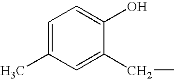
Synthesis of 1-(4-methylphenyl)piperidine
A reaction container was charged with 1,5-dibromopentane (43 g, 186.6 mmol), sodium carbonate (30 g, 280 mmol) and 100 ml of methanol which were weighed and the mixture was stirred at ambient temperature. Then, p-toluidine (10 g, 93.3 mmol) was dissolved in methanol (50 ml) and the solution was added dropwise to the reaction solution. The reaction solution was heated to 55° C. and stirred for 5 hours. The reaction solution was filtered and the resulting filtrate was concentrated under a reduced pressure. The resulting oily mixture was dissolved in ethyl acetate, which was washed with aqueous saturated sodium bicarbonate by using a separating funnel and extracted with 3% hydrochloric acid. Sodium bicarbonate was added to the water phase with stirring the water phase to neutralize it and then the water phase was extracted with ethyl acetate three times. The resulting ethyl acetate solutions were combined and the combined solution was dried using magnesium sulfate and filtered and the filtrate was concentrated under a reduced pressure and distilled under a reduced pressure to obtain 1-(4-methylphenyl)piperidine (8.2 g, yield: 50.3%).
[Boiling point (BP): 110 to 112° C. (2.2 mmHg) 1H-NMR(CDCl3, 300 MHz): 7.07 (d, 2H), 6.86 (d, 2H), 3.09 (t, 4H), 2.27 (s, 3H), 1.73 (qui, 4H), 1.5-1.65 (multi, 2H)]
SYNTHETIC EXAMPLE 2 Synthesis of 4-methylbenzyl(4-methylphenyl)piperidinium bromide
A reaction container was charged with 1-(4-methylphenyl)piperidine (4.0 g, 22.8 mmol) and 10 ml of acetone and the mixture was stirred at ambient temperature. Then, α-bromo-p-xylene (5 g, 27.4 mmol) was added to the reaction solution. The reaction solution was stirred for 3 hours and 20 ml of ethyl acetate was added to the solution. The reaction mixture was further stirred for 30 minutes and subjected to suction filtration to collect a white powder. The resulting powder was dried to obtain 4-methylbenzyl(4-methylphenyl)piperidiniumbromide (6.8 g, yield: 83%).
[Melting point (mp.): 135 to 137° C. 1H-NMR(CDCl3, 300 MHz): 7.33 (d, 2H) 7.25 (d, 2H) 6.95 (d, 2H), 6.83 (d, 2H), 5.28 (s, 2H), 4.89 (t, 2H), 4.31 (d, 2H), 2.43 (s, 3H), 1.8-2.1 (multi, 3H), 1.5-1.7 (multi, 3H)]
SYNTHETIC EXAMPLE 3 Synthesis of 4-methylphenylbenzylpiperidinium hexafluorophosphate
An aqueous solution prepared by dissolving 4-methylphenylbenzylpiperidinium bromide (13.85 g, 0.04 mmol) in 20 ml of deionized water was mixed with an aqueous solution prepared by dissolving potassium hexafluorophosphate (KPF6, 8.83 g, 0.048 mmol) in 30 ml of deionized water and the produced white solid was collected by filtration. The resulting white solid was washed with 300 ml of deionized water, subjected to filtration and dried to obtain 4-methylphenylbenzylpiperidinium hexafluorophosphate (15.6 g, yield: 95%).
[mp. 203-204° C.; 1H-NMR(CDCl3, 300 MHz): 7.4-7.6 (multi, 5H), 6.98 (d, 2H), 6.83 (d, 2H), 5.40 (d, 2H), 4.90 (t, 2H), 4.42 (d, 2H), 2.25 (s, 3H), 1.8-2.1 (multi, 3H), 1.5-1.7 (multi, 3H)]
SYNTHETIC EXAMPLE 4 Synthesis of 4-methylphenylbenzylpiperidinium tosylate
An aqueous solution prepared by dissolving 4-methylphenylbenzylpiperidinium bromide (13.85 g, 0.04 mmol) and sodium p-toluenesulfonate (9.32 g, 0.048 mmol) in 50 ml of deionized water was extracted with 50 ml of chloroform twice by using a separating funnel. The resulting chloroform phases were combined and the combined solution was washed with 50 ml of deionized water, followed by filtration and drying to obtain 4-methylphenylbenzylpiperidinium tosylate (16.1 g, yield: 92%).
[mp. 176-177° C.; 1H-NMR(CDCl3, 300 MHz): 7.91 (d, 2H), 7.45 (t-3H), 7.37 (multi, 2H), 7.16 (d, 2H), 6.89 (d, 2H), 6.64 (d, 2H), 5.06 (s, 2H), 4.55 (t, 2H), 4.36 (d, 2H), 2.36 (s, 3H), 2.23 (s, 3H), 1.8-2.0 (multi, 3H), 1.5-1.7 (multi, 3H)]
The compounds represented by the general formula (1) to be used in the image forming material of the invention may be used either singly or in combinations of two or more. The content of the compound is preferably 50% or less from the viewpoint of film forming ability, preferably in a range from 0.1% to 30% with the view of obtaining significantly good image forming ability and most preferably in a range from 0.5% to 15% as the amount enabling the compatibility between printing qualities such as printing durability and image forming characteristics at a higher level.
Water-Insoluble and Alkali-Soluble Resin
(A) The water-insoluble and alkali-soluble resin (hereinafter, referred to as an alkali soluble resin as the case may be) to be used for the positive image forming layer according to the invention include homopolymers and copolymers containing an acidic group on the primary chain and/or the side chain in a polymer and mixtures of these polymers.
Among these polymers, those containing the acidic groups given in the following (1) to (6) on the primary chain and/or the side chain thereof are preferable in view of solubility in an alkaline developing solution and the manifestation of dissolution inhibitive ability.
  • (1) Phenol group (—Ar—OH)
  • (2) Sulfonamide group (—SO2NH—R)
  • (3) Substituted sulfonamide type acidic group (hereinafter referred to as “active imide group”) [—SO2NHCOR, —SO2NHSO2R and —CONHSO2R]
  • (4) Carboxylic acid (—CO2H)
  • (5) Sulfonic acid group (—SO3H)
  • (6) Phosphoric acid group (—OPO3H2)
In the (1) to (6), Ar represents a divalent aryl connecting group which may have a substituent and R represents a hydrocarbon group which may have a substituent.
Among the alkali-soluble resins having an acidic group selected from the (1) to (6), alkali-soluble resins having (1) a phenol group, (2) a sulfonamide group and/or (3) an active imide group are preferable and, particularly, alkali-soluble resins having (1) a phenol group or (2) a sulfonamide group are most preferable with the view of securing solubility in an alkaline developer, development latitudes and film strength sufficiently.
As the alkali-soluble resins having an acidic group selected from the (1) to (6), the following compounds may be exemplified.
  • (1) Examples of the alkali-soluble resin having a phenol group may include novolac resins such as condensed polymers of phenol and formaldehyde, condensed polymers of m-cresol and formaldehyde, condensed polymers of p-cresol and formaldehyde, condensed polymers of m-/p-mixed cresol and formaldehyde and phenol, cresol (may be any of m-, p- or a mixture of m-/p-) and formaldehyde and condensed polymers of pyrogallol and acetone. Further, copolymers prepared by copolymerizing compounds having a phenol group on the side chain may be exemplified.
Examples of the compound having a phenol group may include acrylamides, methacrylamides, acrylates, methacrylates having a phenol group or hydroxystyrene.
  • (2) Examples of the alkali-soluble resin having a sulfonamide group may include polymers having as its major constitutional component a minimum structural unit derived from a compound having a sulfonamide group. As compounds such as those described above, compounds having one or more sulfonamide groups in which at least one hydrogen atom is bonded to a nitrogen atom and one or more polymerizable unsaturated groups in a molecule are given as examples. Among these compounds, low molecular compounds having an acryloyl group, aryl group or vinyloxy group and substituted or mono-substituted aminosulfonyl group or substituted sulfonylimino group in a molecule are preferable. The compounds represented by the following formulae (i) to (v) are exemplified as such a low molecular compound.
    Figure US06958205-20051025-C00246

    wherein X1 and X2 independently represent —O— or —NR7, R1 and R4 independently represent a hydrogen atom or —CH3; R2, R5, R9, R12 and R16 independently represent an alkylene group, a cycloalkylene group, an arylene group or an aralkylene group having 1 to 12 carbon atoms and may have a substituent; R3, R7 and R13 independently represent a hydrogen atom or an alkyl group, a cycloalkyl group, an aryl group or an aralkyl group having 1 to 12 carbon atoms and may have a substituent; R6 and R17 independently represent an alkyl group, a cycloalkyl group, an aryl group or an aralkyl group having 1 to 12 carbon atoms and may have a substituent; R8, R10 and R14 independently represent a hydrogen atom or —CH3; R11 and R15 independently represent a single bond, an alkylene group, a cycloalkylene group, an arylene group or an aralkylene group having 1 to 12 carbon atoms and may have a substituent; and Y1 and y2 independently represent a single bond or CO.
Among the compounds represented by the formulae (i) to (v), particularly m-aminosulfonylphenyl methacrylate, N-(p-aminosulfonylphenyl)methacrylamide, N-(p-aminosulfonylphenyl) acrylamide and the like may be preferably used for the positive planographic printing plate of the invention.
  • (3) Examples of the alkali-soluble resin having an active imide group may include polymers having as its major constitutional component a minimum structural unit derived from a compound having an active imide group are given as examples. Examples of compounds such as those described above may include compounds containing one or more active imide groups represented by the following structural general formula and one or more polymerizable unsaturated group in a molecule.
    Figure US06958205-20051025-C00247
Specifically, N-(p-toluenesulfonyl)methacrylamide, N-(p-toluenesulfonyl)acrylamide and the like may be preferably used.
  • (4) Examples of the alkali-soluble resin having a carboxylic acid group may include polymers having as its major constitutional component a minimum structural unit derived from a compound having one or more carboxylic acid groups and one or more polymerizable unsaturated groups in a molecule.
  • (5) Examples of the alkali-soluble resin having a sulfonic acid group may include polymers having as its major constitutional component a minimum structural unit derived from a compound having one or more sulfonic acid groups and one or more polymerizable unsaturated groups in a molecule.
  • (6) Examples of the alkali-soluble resin having a phosphoric acid group may include polymers having as its major constitutional component a minimum structural unit derived from a compound having one or more phosphoric acid groups and one or more polymerizable unsaturated groups in a molecule.
The minimum structural unit having an acidic group selected from the foregoing (1) to (6), which unit constitutes the alkali-soluble resin to be used in the positive image forming layer is not limited to only one type and alkali-soluble resins obtained by copolymerizing two or more minimum structural units having either the same acidic groups or different acidic groups may be used.
The copolymer is those containing the compound which has an acidic group selected from the above (1) to (6) and is to be polymerized in an amount of preferably 10 mol % or more and more preferably 20 mol % or more in the copolymer. When the amount is less than 10 mol %, there is a tendency that the developing latitude is insufficiently improved.
In the invention, when a copolymer is used as an alkali-soluble resin, a compound which does not contain the acidic group of the above (1) to (6) may also be used. Examples of the compound which does not contain the acidic group of the above (1) to (6) may include the compounds described in the following (m1) to (m12). These compounds, however, are not intended to be limiting of the invention.
  • (m1) Acrylates and methacrylates having an aliphatic hydroxyl group such as 2-hydroxyethyl acrylate or 2-hydroxyethyl methacrylate.
  • (m2) Alkyl acrylates such as methyl acrylate, ethyl acrylate, propyl acrylate, butyl acrylate, amyl acrylate, hexyl acrylate, octyl acrylate, benzyl acrylate, 2-chloroethyl acrylate and glycidyl acrylate.
  • (m3) Alkyl methacrylates such as methyl methacrylate, ethyl methacrylate, propyl methacrylate, butyl methacrylate, amyl methacrylate, hexyl methacrylate, cyclohexyl methacrylate, benzyl methacrylate, 2-chloroethyl methacrylate and glycidyl methacrylate.
  • (m4) acrylamides or methacrylamides such as acrylamide, methacrylamide, N-methylolacrylamide, N-ethylacrylamide, N-hexylmethacrylamide, N-cyclohexylacrylamide, N-hydroxyethylacrylamide, N-phenylacrylamide, N-nitrophenylacrylamide and N-ethyl-N-phenylacrylamide.
  • (m5) Vinyl ethers such as ethyl vinyl ether, 2-chloroethyl vinyl ether, hydroxyethyl vinyl ether, propyl vinyl ether, butyl vinyl ether, octyl vinyl ether and phenyl vinyl ether.
  • (m6) Vinyl esters such as vinyl acetate, vinyl chloroacetate, vinyl butyrate and vinyl benzoate.
  • (m7) Styrenes such as styrene, α-methylstyrene, methylstyrene and chloromethylstyrene.
  • (m8) Vinyl ketones such as methyl vinyl ketone, ethyl vinyl ketone, propyl vinyl ketone and phenyl vinyl ketone.
  • (m9) Olefins such as ethylene, propylene, isobutylene, butadiene and isoprene.
  • (m10) N-vinylpyrrolidone, acrylonitrile, methacrylonitrile and the like.
  • (m11) Unsaturated imides such as maleimide, N-acryloylacrylamide, N-acetylmethacrylamide, N-propionylmethacrylamide and N-(p-chlorobenzoyl)methacrylamide.
  • (m12) Unsaturated carboxylic acids such as acrylic acid, methacrylic acid, maleic acid anhydride and itaconic acid.
The alkali-soluble resin having a phenolic hydroxyl group is preferable in view of excellent image-forming ability in exposure using an infrared laser or the like. Specifically, novolac resins such as phenol-formaldehyde resins, m-cresol-formaldehyde resins, p-cresol-formaldehyde resins, m-/p-mixed cresol-formaldehyde resins and phenol/cresol (may be any of m-, p- or a mixture of m-/p-)-formaldehyde resins and pyrogallol-acetone resins are more preferable.
Also, given as further examples of the alkali-soluble resin having a phenolic hydroxyl group are condensates of phenols containing an alkyl group having 3 to 8 carbon atoms as a substituent and formaldehyde, such as t-butylphenol-formaldehyde resins and octylphenol-formaldehyde resins as described in the specification of U.S. Pat. No. 4,123,279.
The alkali-soluble resin has a weight average molecular weight of 500 or more and more preferably 1,000 to 700,000 in view of image forming ability. Also, its number average molecular weight is preferably 500 or more and more preferably 750 to 650,000. The degree of dispersion (weight average molecular weight/number average molecular weight) of the alkali-soluble resin is preferably 1.1 to 10.
Also, these alkali-soluble resins may be used either singly or in combinations of two or more. When the combinations are used, condensates of phenols having an alkyl group having 3 to 8 carbon atoms as a substituent and formaldehyde, such as condensates of t-butylphenol and formaldehyde and condensates of octylphenol and formaldehyde as described in the specification of U.S. Pat. No. 4,123,279, and the alkali-soluble resin having a phenol structure having an electron attractive group on an aromatic ring as described in JP-A No. 2000-241972 submitted previously by the inventors of the invention may be used together.
The total content of the alkali-soluble resin in the invention is preferably 30 to 98% by weight and more preferably 40 to 95% by weight based on the total solid of the image forming layer. When the content is less than 30% by weight, the durability tends to be impaired whereas when the content exceeds 98% by weight, the sensitivity and the image formability tend to be reduced.
Light-Heat Converting Agent
As the light-heat converting agent used in the invention, any material may be used without any limitation to the absorption wavelength range as far as it is a material which absorbs the light-energy radiation used for recording to generate heat. However, infrared-absorbable dyes and pigments having an absorption maximum in a wavelength range from 760 nm to 1200 nm are preferable from the viewpoint of adaptability to an easily available high-output laser.
As the dye, commercially available dyes and, for example known dyes described in literature such as “Dye Handbook” (edited by Organic Synthetic Chemical Association, published in 1970) may be utilized. Specific examples of these dyes may include azo dyes, metal complex azo dyes, pyrazolone azo dyes, naphthoquinone dyes, anthraquinone dyes, phthalocyanine dyes, carbonium dyes, quinoneimide dyes, methine dyes, cyanine dyes, squalilium dyes, pyrylium salts, metal thiolate complexes, oxonol dyes, diimmonium dyes, aminium dyes and croconium dyes.
Preferable examples of the dye may include cyanine dyes described in JP-A Nos. 58-125246, 59-84356, 59-202829, 60-78787 and the like and methine dyes described in JP-A Nos. 58-173696, 58-181690, 58-194595 and the like, naphthoquinone dyes described in JP-A Nos. 58-112793, 58-224793, 59-48187, 59-73996, 60-52940, 60-63744 and the like, squalilium dyes described in JP-A No. 58-112792 and the like and cyanine dyes described in U.K. patent No. 434,875.
Near-infrared absorbing sensitizer described in U.S. Pat. No. 5,156,938 are also preferably used. Substituted arylbenzo(thio)pyrylium salts described in U.S. Pat. No. 3,881,924, trimethinethiapyrylium salts described in JP-A No. 57-142645 (U.S. Pat. No. 4,327,169), pyrylium compounds described in JP-A Nos. 58-181051, 58-220143, 59-41363, 59-84248, 59-84249, 59-146063 and 59-146061, cyanine dyes described in JP-A No. 59-216146, pentamethinethiopyrylium salts and the like described in U.S. Pat. No. 4,283,475 and pyrylium compounds disclosed in Japanese Patent Application Publication (JP-B) Nos. 5-13514 and 5-19702 are also preferably used.
Also, other preferable examples of the dye may include near-infrared absorbing dyes represented by the formulae (I) or (II) described in the specification of U.S. Pat. No. 4,756,993.
As examples of particularly preferable dyes among these dyes, cyanine dyes, phthalocyanine dyes, oxonol dyes, squalilium dyes, pyrylium salts, thiopyrylium dyes and nickel thiolate complexes are given. Moreover, dyes represented by the following formulae (a) to (e) are preferable because these dyes have superior light-heat conversion efficiency. In particular, cyanine dyes represented by the following general formula (a) are most preferable because these dyes impart high polymerization activity when used in the polymerizable composition according to the invention and have high stability and profitability.
Figure US06958205-20051025-C00248
In the general formula (a), X1 represents a hydrogen atom, a halogen atom, —NPh2, X2-L1 or a group shown below. Here, X2 represents an oxygen atom or a sulfur atom, L1 represents a hydrocarbon group having 1 to 12 carbon atoms, an aromatic ring having a heteroatom or a hydrocarbon group containing a heteroatom and having 1 to 12 carbon atoms. Here, the heteroatom represents N, S, O, a halogen atom or Se.
Figure US06958205-20051025-C00249
R1 and R2 independently represent a hydrocarbon group having 1 to 12 carbon atoms. R1 and R2 are independently preferably a hydrocarbon group having 2 or more carbon atoms in view of the preservation stability of a light-sensitive layer coating solution and, moreover, R1 and R2 particularly preferably bond to each other to form a five-membered or six-membered ring.
Ar1 and Ar2, which may be the same or different, independently represent an aromatic hydrocarbon group which may have a substituent. Preferable examples of the aromatic hydrocarbon group include a benzene ring or naphthalene ring. Also, preferable examples of the substituent include hydrocarbon groups having 12 or less carbon atoms, halogen atoms and alkoxy groups having 12 or less carbon atoms. Y1 and Y2, which may be the same or different, independently represent a sulfur atom or a dialkylmethylene group having 12 or less carbon atoms. R3 and R4, which may be the same or different, independently represent a hydrocarbon group which may have a substituent and has 20 or less carbon atoms. Preferable examples of the substituent include alkoxy groups having 12 or less carbon atoms, carboxyl groups and sulfo groups. R5, R6, R7 and R8, which may be the same or different, independently represent a hydrogen atom or a hydrocarbon group having 12 or less carbon atoms. A hydrogen atom is preferable from the viewpoint of the availability of raw materials. Also, Za represents a counter anion. In the case where any one of R1 to R8 is substituted with a sulfo group, Za+ is not required. Za is preferably halogen ions, perchloric acid ions, tetrafluoroborate ions, hexafluorophosphate ions and sulfonic acid ions and particularly preferably perchloric acid ions, hexafluorophosphate ions and arylsulfonic acid ions in view of the preservation stability of a light-sensitive layer coating solution.
In the invention, specific examples of the cyanine dyes which are represented by the general formula (a) and preferably used may include those described in the specification of Japanese Patent Application No. 11-310623, paragraphs No. [0017] to No. [0019], the specification of Japanese Patent Application No. 2000-224031, paragraphs No. [0012] to No. [0038] and the specification of Japanese Patent Application No. 2000-211147, paragraphs No. [0012] to No. [0023], besides dyes exemplified below.
Figure US06958205-20051025-C00250
Figure US06958205-20051025-C00251
Figure US06958205-20051025-C00252
In the general formula (b), L represents a methine chain having 7 or more conjugate carbon atoms. The methine chain may have a substituent and the substituents may bond to each other to form a ring. Zb+ represents a counter cation. Preferable examples of the counter cation include ammonium, iodonium, sulfonium, phosphonium, pyridinium and alkali metal cations (Ni+, K+ and Li+). R9 to R14 and R15 to R20 independently represent a hydrogen atom or a substituent selected from a halogen atom, a cyano group, an alkyl group, an aryl group, an alkenyl group, an alkynyl group, a carbonyl group, a thio group, a sulfonyl group, a sulfinyl group, an oxy group and an amino group or a substituent of a combination of two or three of these groups and may bond to each other to form a ring. Here, compounds in which L represents a methine chain having 7 conjugate carbon atoms and compounds in which all of R9 to R14 and R15 to R20 represent hydrogen atoms in the general formula (b) are preferable from the viewpoint of availability and effects.
In the invention, specific examples of the dyes represented by the general formula (b) and preferably used may include the following compounds.
Figure US06958205-20051025-C00253
Figure US06958205-20051025-C00254
In the general formula (c), Y3 and Y4 independently represent an oxygen atom, a sulfur atom, a selenium atom or a tellurium atom. M represents a methine chain having 5 or more conjugate carbon atoms. R21 to R24 and R25 to R28, which may be the same or different, independently represent a hydrogen atom, a halogen atom, a cyano group, an alkyl group, an aryl group, an alkenyl group, an alkynyl group, a carbonyl group, a thio group, a sulfonyl group, a sulfinyl group, an oxy group or an amino group. Also, in the general formula, Za represents a counter anion and has the same meaning as in the general formula (a).
In the invention, specific examples of the dyes represented by the general formula (c) and preferably used may include the following compounds.
Figure US06958205-20051025-C00255
Figure US06958205-20051025-C00256
In the above general formula (d), R29 to R31 independently represent a hydrogen atom, an alkyl group or an aryl group. R33 and R34 independently represent an alkyl group, a substituted oxy group or a halogen atom. n and m independently denote an integer from 0 to 4. R29 and R30 or R31 and R32may bond to each other to form a ring, also, R29 and/or R30 and R33, and R31 and/or R32 and R34 may bond to each other to form a ring. When plural R33s and R34s are respectively present, R33s among them and R34s among them may bond to each other to form a ring. X2 and X3 independently represent a hydrogen atom, an alkyl group or an aryl group and at least one of X2 and X3 represents a hydrogen atom or an alkyl group. Q represents a trimethine group or a pentamethine group which may have a substituent and may form a ring in combination with a divalent organic group. Zc represents a counter anion and has the same meaning as Za in the above general formula (a).
In the invention, specific examples of the dyes represented by the general formula (d) and preferably used may include the following compounds.
Figure US06958205-20051025-C00257
General Formula (e)
Figure US06958205-20051025-C00258
In the above general formula (e), R35 to R50 independently represent a hydrogen atom, a halogen atom, a cyano group, an alkyl group, an aryl group, an alkenyl group, an alkynyl group, a hydroxyl group, a carbonyl group, a thio group, a sulfonyl group, a sulfinyl group, an oxy group, an amino group or an onium salt structure which may have a substituent. M represents two hydrogen atoms, or a metal salt, a halometal group or an oxymethal group. Examples of the metal atom contained there include IA, IIA, IIIB or IVB group atoms, the first, second or third period transition metals in the periodic table and a lanthanoid element. Among these elements, copper, magnesium, iron, zinc, cobalt, aluminum, titanium and vanadium are preferable.
In the invention, specific examples of the dyes represented by the general formula (e) and preferably used in the invention may include the following compounds.
Figure US06958205-20051025-C00259
Examples of the pigments to be used as the infrared absorber in the invention include commercially available pigments and pigments described in Color Index (C.I.) Handbook, “LATEST PIGMENT HANDBOOK” (Japan Pigment Technology Association, published in 1977), “LATEST PIGMENT APPLIED TECHNOLOGIES” (CMC Shuppan, published in 1986), “PRINTING INK TECHNOLOGIES” CMC Shuppan, published in 1984).
Examples of the type of pigment, black pigments, yellow pigments, orange pigments, brown pigments, red pigments, violet pigments, blue pigments, green pigments, fluorescent pigments, metal powder pigments and polymer binding dyes. Specifically, insoluble azo pigments, azo lake pigments, condensed azo pigments, chelate azo pigments, phthalocyanine pigments, anthraquinone pigments, perylene and perinone pigments, thioindigo pigments, quinacridone pigments, dioxazine pigments, isoindolinone pigments, quinophthalone pigments, dyeing lake pigments, azine pigments, nitroso pigments, nitro pigment, natural pigments, fluorescent pigments, inorganic pigments and carbon black may be used. Among these pigments, carbon black is desirable.
These pigments may be used either without carrying out surface treatment or after carrying out surface treatment. As surface treating methods, a method in which a resin or wax is applied to pigment grains, a method in which a surfactant is stuck and a method in which a reactive material (e.g., a silane coupling agent, epoxy compound or polyisocyanate) is bound with the surface of a pigment are considered. The surface treating methods are described in “QUALITIES AND APPLICATION OF METAL SOAPS” (Saiwai Shobo), “PLINTING INK TECHNOLOGIES” (CMC Shuppan, published in 1984) and “LATEST PIGMENT APPLIED TECHNOLOGIES” (CMC Shuppan, published in 1986).
The particle diameter of the pigment is preferably in a range from 0.01 μm to 10 μm, more preferably in a range from 0.05 μm to 1 μm and most preferably in a range from 0.1 μm to 1 μm. When the particle diameter is less than 0.01 μm, this is undesirable in the point of the stability of the dispersion in the coating solution for the image light-sensitive layer. When the particle diameter exceeds 10 μm, this is undesirable in the point of the uniformity of the image light-sensitive layer.
As a method for dispersing the pigment, known dispersing technologies used for the production of ink or toners may be used. Examples of dispersing machines include a ultrasonic dispersing machine, sand mill, attritor, pearl mill, super mill, ball mill, impeller, disperser, KD mill, colloid mill, dynatron, three-roll mill and pressure kneader. The details of these dispersing machines are described in “LATEST PIGMENT APPLIED TECHNOLOGIES” (CMC Shuppan, published in 1986).
The pigment or dye which is a light-heat converting agent may be added in a proportion of 0.01 to 50% by weight and preferably 0.1 to 30% by weight, and particularly preferably 0.5 to 10% by weight in the case of a dye and 0.1 to 10% by weight in the case of a pigment on the basis of the total solid constituting the image forming layer.
In the case where the pigment or dye is used in the upper layer of a laminated light-sensitive material, the freedom of the amount to be added is higher according to the situation free from a problem concerning developing ability on the interface of the substrate and the pigment or dye may be added in a proportion of 0.01 to 50% by weight, preferably 0.1 to 40% by weight and particularly preferably 0.5 to 30% by weight based on the total solid.
Other Components
When the positive image forming layer according to the invention is formed, various additives may be further added according to the need. For example, materials, such as onium salts, o-quinonediazide compounds, aromatic sulfone compounds and aromatic sulfonates, which are heat-decomposable and substantially lowers the solubility of an aqueous alkali-soluble high molecular compound in a non-decomposed state are preferably used together with the view of improving inhibition of the solubility of an image portion in a developing solution. Examples of the onium salts may include diazonium salts, ammonium salts, phosphonium salts, iodonium salts, sulfonium salts, selenonium salts and arsonium salts.
Preferable examples of the onium salt used in the invention include diazonium salts described in S. I. Schlesinger, Photogr. Sci. Eng., 18, 387 (1974), T. S. Bal et al. Polymer, 21, 423 (1980) and diazonium salts described in the publication of JP-A No. 5-158230, ammonium salts described in each specification of U.S. Pat. Nos. 4,069,055, 4,069,056 and JP-A No. 3-140140, phosphonium salts described in D. C. Necker et al, Macromolecules, 17, 2468 (1984), C. S. Wen at al, Teh, Proc. Conf. Rad. Curing ASIA, p478 Tokyo, October (1988), U.S. Pat. Nos. 4,069,055 and 4,069,056, iodonium salts described in J. V. Crivello et al, Macromolecules, 10(6), 1307 (1977), Chem. & Eng. News, November 28, p31 (1988), E.P. No. 104, 143, U.S. Pat. Nos. 339,049, 410,201, JP-A Nos. 2-150848 and 2-296514, sulfonium salts described in J. V. Crivello et al, Polymer J. 17, 73 (1985), J. V. Crivello et al. J. Org. Chem., 43, 3055 (1978), W. R. Watt et al, J. Polymer Sci., Polymer Chem. Ed., 22, 1789 (1984), J. V. Crivello et al, Polymer Bull., 14, 279 (1985), J. V. Crivello et al, Macromolecules, 14(5), 1141 (1981), J. V. Crivello et al, J. Polymer Sci., Polymer Chem. Ed., 17, 2877 (1979), E.P. Nos. 370, 693, 233,567, 297,443, 297,442, U.S. Pat. Nos. 4,933,377, 3,902,114, 410,201, 339,049, 4,760,013, 4,734,444, and 2,833,827, German Patent Nos. 2,904, 626, 3,604,580 and 3,604,581, selenonium salts described in J. V. Crivello et al, Macromolecules, 10(6), 1307 (1977), J. V. Crivello et al, J. Polymer Sci., and Polymer Chem. Ed., 17, 1047 (1979) and arsonium salts described in C. S. Wen et al, Teh, Proc. Conf. Rad. Curing ASIA, p478 Tokyo, October (1988).
Among these onium salts, diazonium salts are particularly preferable. Also, particularly preferable examples of these diazonium salts include those described in the publication of JP-A No. 5-158230.
Examples of the counter anion of the onium salt may include tetrafluoroboric acid, hexafluoroboric acid, triisopropylnaphthalenesulfonic acid, 5-nitro-o-toluenesulfonic acid, 5-sulfosalicylic acid, 2,5-dimethylbenzenesulfonic acid, 2,4,6-trimethylbenzenesulfonic acid, 2-nitrobenzenesulfonic acid, 3-chlorobenzenesulfonic acid, 3-bromobenzenesulfonic acid, 2-fluorocaprylnaphthalenesulfonic acid, dodecylbenzenesulfonic acid, 1-naphthol-5-sulfonic acid, 2-methoxy-4-hydroxy-5-benzoyl-benzenesulfonic acid and paratoluenesulfonic acid. Among these counter anions, particularly hexafluorophosphoric acid and alkyl aromatic sulfonic acids such as triisopropylnaphthalenesulfonic acid and 2,5-dimethylbenzenesulfonic acid are preferable.
Preferable examples of quinonediazides may be o-quinonediazide compounds. o-Quinonediazide compounds to be used in the invention are compounds having at least one o-quinonediazide group, which compounds are increased in alkali solubility by heat decomposition and various compounds may be used. o-Quinonediazide is thermally decomposed to lose the ability of inhibiting the dissolution of a binder and itself is changed to an alkali-soluble material. Namely, o-quinonediazide promotes the solubility of light-sensitive materials by these two effects. As the o-quinonediazide compound to be used in the invention, for example compounds described in J. Koser “Light-sensitive Systems” (John Wiley & Sons. Inc.) pp339-352 may be used and particularly sulfonates or sulfonic acid amides of o-quinonediazide obtained by reacting the o-quinonediazide compound with various aromatic polyhydroxy compounds or aromatic amino compounds are preferable. Also, esters of benzoquinone-(1,2)diazidosulfonic acid chloride or naphthoquinone-(1,2)-diazido-5-sulfonic acid chloride and a pyrogallol-acetone resin as described in the publication of JP-B No. 43-28403 and esters of benzoquinone-(1,2)-diazidosulfonic acid chloride or naphthoquinone-(1,2)-diazido-5-sulfonic acid chloride and a phenol-formaldehyde resin as described in U.S. Pat. Nos. 3,046,120 and 3,188,210 are preferably used.
Moreover, esters of naphthoquinone-(1,2)-diazido-4-sulfonic acid chloride and a phenol-formaldehyde resin or cresol-formaldehyde resin and esters of naphthoquinone-(1,2)-diazido-4-sulfonic acid chloride and a pyrogallol-acetone resin are preferably used. Other useful o-quinonediazide compounds have been reported in many patents and used. Examples of these compounds include those described in each specification of JP-A Nos. 47-5303, 48-63802, 48-63803, 48-96575, 49-38701, 48-13354, JP-B Nos. 41-11222, 45-9610, 49-17481, U.S. Pat. Nos. 2,797,213, 3,454,400, 3,544,323, 3,573,917, 3,674,495, 3,785,825, U.K. Patent Nos. 1,227,602, 1,251,345, 1,267,005, 1,329,888, 1,330,932 and German patent No. 854,890.
The amount of o-quinonediazide compound to be added is in a range preferably 1 to 50% by weight, more preferably 5 to 30% by weight and particularly preferably 10 to 30% by weight based on the total solid of the printing plate material. These compounds may be used singly, but may be used as a mixture of various types.
The amount of the additives other than o-quinonediazide compound is preferably 1 to 50% by weight, more preferably 5 to 30% by weight and particularly preferably 10 to 30% by weight. The additives and the binder in the invention are preferably contained in the same layer.
Also, cyclic acid anhydrides, phenols and organic acids may be further used together to improve sensitivity. As the cyclic acid anhydride, phthalic acid anhydride, tetrahydrophthalic acid anhydride, hexahydrophthalic acid anhydride, 3,6-endoxy-Δ4-tetrahydrophthalic acid anhydride, tetrachlorophthalic acid anhydride, maleic acid anhydride, chloromaleic acid anhydride, α-phenylmaleic acid anhydride, succinic acid anhydride and pyromellitic acid anhydride which are described in the specification of U.S. Pat. No. 4,115,128 may be used. As examples of the phenols, bisphenol A, p-nitrophenol, p-ethoxyphenol, 2,4,4′-trihydroxybenzophenone, 2,3,4-trihydroxybenzophenone, 4-hydroxybenzophenone, 4,4′,4″-trihydroxytriphenylmethane, 4,4′,3″,4″-tetrahydroxy-3,5,3′,5′-tetreamethyltriphenylmethane are given. Further, examples of the organic acids include sulfonic acids, sulfinic acids, alkylsulfuric acids, phosphonic acids, phosphates and carboxylic acids as described in each publication of JP-A Nos. 60-88942, 2-96755 and the like. Specific examples of these acids include p-toluenesulfonic acid, dodecylbenzenesulfonic acid, p-toluenesulfinic acid, ethylsulfuric acid, phenylphosphonic acid, phenylphosphinic acid, phenyl phosphate, diphenyl phosphate, benzoic acid, isophthalic acid, adipic acid, p-toluylic acid, 3,4-dimethoxybenzoic acid, phthalic acid, terephthalic acid, 4-cyclohexene-1,2-dicarboxylic acid, erucic acid, lauric acid, n-undecanoic acid and ascorbic acid. The proportion occupied by the cyclic acid anhydride, phenols and organic acids in the printing plate material is preferably 0.05 to 20% by weight, more preferably 0.1 to 15% by weight and particularly preferably 0.1 to 10% by weight.
Also, nonionic surfactants as described in the publication of JP-A Nos. 62-251740 and 3-208514, amphoteric surfactants as described in the publication of JP-A Nos. 59-121044 and 4-13149, siloxane compounds as described in the publication of European Patent No. 950,517 and copolymers of fluorine-containing monomers as described in JP-A No. 11-288093 may be added to the image forming layer coating solution according to the invention.
Specific examples of the nonionic surfactant include sorbitan tristearate, sorbitan monopalmitate, sorbitan triorate, stearic acid monoglyceride and polyoxyethylene nonylphenyl ether. Specific examples of the amphoteric surfactant include alkyldi(aminoethyl)glycine, alkylpolyaminoethylglycine hydrochloride, 2-alkyl-N-carboxyethyl-N-hydroxyethylimidazoliniumbetaine and N-tetradecyl-N,N-betaine compound (e.g., trademark: “Amorgen K”, manufactured by Dai-ichi Kogyo Co.).
As the siloxane compound, a block copolymer of dimethylsiloxane and polyalkylene oxide is preferable. Specific examples of the siloxane compound may include polyalkylene oxide-modified silicone such as DBE-224, DBE-621, DBE-712, DBP-732 and DBP-534 manufactured by Chisso Corporation and Tego Glide 100 manufactured by Tego in Germany.
The proportion occupied by the nonionic surfactant and amphoteric surfactant in the printing plate material is preferably 0.05 to 15% by weight and more preferably 0.1 to 5% by weight.
A print-out agent for obtaining a visible image just after heating by exposure and dyes or pigments used as image colorants may be added in the image forming layer according to the invention.
Typical examples of the print-out agent may include a combination of a compound which releases an acid by the heat resulted from exposure and an organic dye capable of forming a salt. Specific examples of the combination may include combinations of o-naphthoquinonediazido-4-sulfonic acid halogenide and a salt-formable organic dye as described in each publication of JP-A Nos. 50-36209 and 53-8128 and combinations of a trihalomethyl compound and a salt-formable organic dye as described in each publication of JP-A Nos. 53-36223, 54-74728, 60-3626, 61-143748, 61-151644 and 63-58440. Examples of such a trihalomethyl compound include oxazole compounds and triazine compounds, which both have superior stability with time and give a clear print-out image.
As the colorant for an image, other dyes besides the salt-formable organic dyes may be used. As preferable examples of the dyes including these salt-formable organic dyes include oil-soluble dyes and basic dyes. Specific examples of these dyes may include Oil Yellow #101, Oil Yellow #103, Oil Pink #312, Oil Green BG, Oil Blue BOS, Oil Blue #603, Oil Black BY, Oil Black BS, Oil Black T-505 (these products are manufacture by Orient Chemical Industries, Ltd.), Victoria Pure Blue, Crystal Violet (CI42555), Methyl Violet (CI42535), Ethyl Violet, Rhodamine B (CI145170B), Malachite Green (CI42000) and Methylene Blue (CI52015). Also, dyes described in the publication of JP-A No. 62-293247 are particularly preferable. These dyes may be added to the printing plate material in an amount 0.01 to 10% by weight and preferably 0.1 to 3% by weight based on the total solid of the printing plate material. Moreover, a plasticizer may be compounded in the printing plate material of the invention according to the need to impart, for example, the flexibility to a film. For example, oligomers or polymers of butylphthalyl, polyethylene glycol, tributyl citrate, diethyl phthalate, dibutyl phthalate, dihexyl phthalate, dioctyl phthalate, tricresyl phosphate, tributyl phosphate, trioctyl phosphate, tetrahydrofurfuryl oleate and acrylic acid or methacrylic acid are used.
Besides the additives, epoxy compounds, vinyl ethers, phenol compounds having a hydroxymethyl group and phenol compounds having a alkoxymethyl group as described in the publication of JP-A No. 8-276558 and cross-linkable compounds having an alkali-dissolution inhibitive function as described in JP-A No. 11-160860 which has been previously proposed by the inventors of the invention may be properly added according to the purpose.
The image forming material of the invention comprises the above-mentioned image forming layer on an appropriate substrate and are applicable in various uses such as planographic printing plate precursors, color-proofs and display materials, and particularly is useful for a heat mode type planographic printing plate precursor enabling direct plate-making by exposure using an infrared laser.
A specific embodiment will be hereinafter explained by giving a case of applying the image forming material of the invention to a planographic printing plate precursor.
The planographic printing plate precursor according to the invention may be produced by applying a coating solution for a light-sensitive layer (image forming layer) and a solution, obtained by dissolving components for coating solutions of desired layers in a solvent, on an appropriate substrate. Also, a protective layer, a resin intermediate layer, a back-coat layer and the like may be formed according to the need.
Examples of the solvent used here may include, though not limited to, ethylene dichloride, cyclohexanone, methyl ethyl ketone, methanol, ethanol, propanol, ethylene glycol monomethyl ether, 1-methoxy-2-propanol, 2-methoxyethyl acetate, 1-methoxy-2-propyl acetate, dimethoxyethane, methyl lactate, ethyl lactate, N,N-dimethylacetamide, N,N-dimethylformamide, tetramethylurea, N-methylpyrrolidone, dimethylsulfoxide, sulfolane, γ-butyrolactone and toluene. These solvents are used either singly or by mixing them.
The concentration of the components (total content including the additives) in the solvent is 1 to 50% by weight.
The coating amount (solid content) on the substrate after applying and drying is preferably 0.5 to 5.0 g/m2 in general in the case of the image forming layer of the planographic printing plate precursor though it depends on the use. With an increase in the coating amount, apparent sensitivity is heightened, but the film characteristics of the image forming layer is lowered.
Various methods may be used as the coating method and examples of these methods may include bar coater coating, rotational coating, spray coating, curtain coating, dip coating, air knife coating, blade coating and roll coating.
Surfactants for bettering coatability, for example, fluorine-containing surfactants as described in the publication of JP-A No. 62-170950 may be compounded in the image forming layer of the invention. The amount of the surfactant is preferably 0.01 to 1% by weight and more preferably 0.05 to 0.5% by weight based on the total solid of the image forming layer.
Resin Intermediate Layer
The planographic printing plate precursor may be provided with a resin intermediate layer between the image forming layer and the substrate according to the need.
With the provision of this resin intermediate layer, the image forming layer which is an infrared sensible layer improved in solubility in an alkali developing solution by exposure is positioned on or close to the exposed surface, whereby the sensitivity to an infrared laser is bettered. Also, the provision of the resin intermediate layer has such an advantage that the resin intermediate layer consisting of a polymer exists between the image forming layer and the substrate and functions as an insulating layer, so that the heat generated by exposure is not diffused to the substrate and used efficiently for the formation of an image, thereby attaining high sensitization. Also, in the unexposed portion, the image forming layer, which prevents the penetration of an alkali developing solution, itself functions as a protective layer for protecting the resin intermediate layer and therefore the developing stability is bettered and an image superior in discrimination is formed and also, it is considered that the stability with time is secured. On the other hand, in the exposed portion, the components of the image forming layer whose dissolution inhibition ability is dissolved is promptly dissolved in a developing solution, dispersed. Further, because the resin intermediate layer present adjacent to the substrate itself is constituted of an alkali-soluble polymer, it has high solubility in a developing solution and therefore it dissolves promptly without generating a residual film, even in the case of using a developing solution reduced in activity, which also contributes to an improvement in developing ability and this resin intermediate layer is therefore considered to be useful.
Substrate
Examples of the substrate used in the invention include dimensionally stable plate materials, such as paper, paper laminated with plastic (e.g., polyethylene, polypropylene and polystyrene), metal plates (e.g., aluminum, zinc and copper), plastic films (e.g., cellulose diacetate, cellulose triacetate, cellulose propionate, cellulose butyrate, cellulose acetate butyrate, cellulose nitrate, polyethylene terephthalate, polyethylene, polystyrene, polypropylene, polycarbonate and polyvinylacetal), paper or plastic films on which metals as mentioned above are laminated or deposited.
The substrate used in the invention is preferably a polyester film or an aluminum plate when it is used for a planographic printing plate precursor. Among these materials, an aluminum plate which has high dimensional stability and is relatively inexpensive is particularly preferable. A preferable aluminum plate is a pure aluminum plate and an alloy plate containing aluminum as major components and a trace amount of foreign elements and also, may be a plastic film on which aluminum is laminated or deposited. Examples of the foreign elements contained in the aluminum alloy include silicon, iron, manganese, copper, magnesium, chromium, zinc, bismuth, nickel and titanium. The content of these foreign elements in the alloy is 10% by weight or less. Particularly preferable aluminum in the invention is pure aluminum. However, it is difficult to produce perfectly pure aluminum from the viewpoint of refining technologies and therefore the aluminum plate may contain trace foreign elements.
As aforementioned, the composition of the aluminum plate applied to the invention is not specified and aluminum plates which have been well known and commonly used may be used appropriately. The thickness of the aluminum plate used in the invention is about 0.1 mm to 0.6 mm, preferably 0.15 mm to 0.4 mm and particularly preferably 0.2 mm to 0.3 mm.
Prior to the roughing of the aluminum plate, degreasing treatment using surfactants, organic solvents or an aqueous alkaline solution is carried out to remove rolling oil on the surface as desired. The surface roughing treatment of the surface of the aluminum plate is carried out by various methods. For example, the surface roughing treatment is carried out using a method in which a surface is roughened mechanically, a method in which a surface is electrochemically roughened by melting the surface or a method in which a surface is selectively melted chemically. As the mechanical method, a known method such as a polishing method which uses balls, brushing, blasting or buffing may be used. Also, as the electrochemical surface roughing method, there is a method in which a surface is roughened using d.c. current or a.c. current in hydrochloric acid or nitric acid electrolyte. Also, as disclosed in the publication of JP-A No. 54-63902, a method for which the both are combined may be utilized. The aluminum plate which is surface-roughened in this manner is subjected to alkali etching treatment and neutralizing treatment as required and then to anodic oxidation treatment as desired to heighten the moisture-retentivity and wear resistance of the surface. As the electrolyte used for the anodic oxidation treatment of the aluminum plate, it is possible to use various electrolytes which form a porous oxidation film and sulfuric acid, phosphoric acid, oxalic acid, chromic acid or a mixture of these acids is used in general. The concentration of the electrolyte is properly determined by the type of electrolyte.
General treating conditions of the anodic oxidation are preferably in the following ranges though they can be unspecified as a whole because they differ depending on the type of electrolyte: concentration of the electrolyte: 1 to 80% by weight solution, solution temperature: 5 to 70° C., current density: 5 to 60 A/dm2, voltage: 1 to 100 V and electrolyzation time: 10 seconds to 5 minutes. When the amount of the anodic oxidation film is less than 1.0 g/m2, insufficient printing durability is obtained and the non-image portion of the planographic printing plate is easily dmaged, so that a so-called “damage stain”, that is, a phenomenon that ink is stuck to the damaged portion during printing, tends to occur. After the anodic oxidation treatment is performed, the surface of the aluminum is made hydrophilic according to the need. As the method for making an aluminium surface hydrophilic, there is an alkali metal silicate (e.g., aqueous sodium silicate solution) method such as those described in U.S. Pat. No. 2,714,066, U.S. Pat. No. 3,181,461, U.S. Pat. No. 3,280,734 and U.S. Pat. No. 3,902,734. In this method, the substrate is dipped in an aqueous sodium silicate solution and, if necessary, is electrified. Besides the above treatment, methods in which the substrate is treated with potassium fluorozirconate as disclosed in the publication of JP-B No. 36-22063 and a method in which the substrate is treated with polyvinylphosphonic acid as disclosed in U.S. Pat. Nos. 3,276,868, 4,153,461 and 4,689,272 are used.
The planographic printing plate precursor according to the invention has the positive image forming layer on the substrate and may be provided with an undercoat layer between the image forming layer and the substrate according to the need.
Various organic compounds are used as the components for the undercoat layer. The organic compound is selected from, for example, carboxymethyl cellulose, dextrin, gum arabic, phosphonic acids having an amino group such as 2-aminoethylphosphonic acid, organic phosphonic acids such as phenylphosphonic acid, naphthylphosphonic acid, alkylphosphonic acid, glycerophosphonic acid, methylenediphosphonic acid and ethylenediphosphonic acid, which may have a substituent, organic phosphoric acids such as phenylphosphoric acid, naphthylphosphoric acid, alkylphosphoric acid and glycerophosphoric acid, which may have a substituent, organic phosphinic acids such as phenylphosphinic acid, naphthylphosphinic acid, alkylphosphinic acid and glycerophosphinic acid, which may have a substituent, amino acids such as glycine and β-alanine and hydrochlorides of amine having a hydroxy group such as hydrochlorides of triethanolamine. These compounds may be used by mixing two or more.
This organic undercoat layer may be formed by a method in which a solution obtained by dissolving the organic compound in water or an organic solvent such as methanol, ethanol or methyl ethyl ketone or a mixture of these solvents is applied to the aluminum plate and dried or by a method in which the aluminum plate is dipped in a solution obtained by dissolving the organic compound in water or an organic solvent such as methanol, ethanol and methyl ethyl ketone or a mixture of these solvents to make the compounds adsorb to the aluminum plate, which is then washed with water or the like and dried. In the former method, a solution in which the concentration of the organic compound is 0.005 to 10% by weight may be applied using various methods. Also, in the latter method, the concentration of the solution is 0.01 to 20% by weight and preferably 0.05 to 5% by weight, the dipping temperature is 20 to 90° C. and preferably 25 to 50° C. and the dipping time is 0.1 seconds to 20 minutes and preferably 2 seconds to 1 minute. The solution to be used for this may be adjusted to pH 1 to 12 by using a basic material such as ammonia, triethylamine or potassium hydroxide and an acidic material such as hydrochloric acid or phosphoric acid. Also, a yellow dye may be added to improve the reproducibility of the tone of the image forming material.
The amount of the organic undercoat layer to be applied is properly 2 to 200 mg/m2 and preferably 5 to 100 mg/m2. If the above amount to be applied is less than 2 mg/m2, sufficient printing durability is not obtained. Also, even if the amount is greater than 200 mg/M2, the same result is obtained.
The positive planographic printing plate precursor produced in the above manner is usually subjected to an image exposure process and developing treatment.
As a light source of the rays used for image exposure, light sources having emitting wavelength in a range from the near-infrared region to the infrared region are preferable and a solid laser and a semiconductor laser are particularly preferable.
As a developing solution and a replenishing solution used in the production of the planographic printing plate of the invention, a conventionally known aqueous alkali solution may be used.
Examples of the alkali include inorganic alkali salts such as sodium silicate, potassium silicate, sodium tertiary phosphate, potassium tertiary phosphate, ammonium tertiary phosphate, sodium secondary phosphate, potassium secondary phosphate, ammonium secondary phosphate, sodium carbonate, potassium carbonate, ammonium carbonate, sodium bicarbonate, potassium bicarbonate, ammonium bicarbonate, sodium borate, potassium borate, ammonium borate, sodium hydroxide, ammonium hydroxide, potassium hydroxide and lithium hydroxide. Also, organic alkali agents such as monomethylamine, dimethylamine, trimethylamine, monoethylamine, diethylamine, triethylamine, monoisopropylamine, diisopropylamine, triisopropylamine, n-butylamine, monoethanolamine, diethanolamine, triethanolamine, monoisopropanolamine, diisopropanolamine, ethyleneimine, ethylenediamine and pyridine may be used. These alkali agents are used either singly or in combinations of two or more.
Particularly preferable developing solutions among these alkali agents are aqueous solutions of silicates such as sodium silicate and potassium silicate. The reason is that developing ability can be controlled by the ratio and concentrations of silicon oxide SiO2 which is a component of the silicate and an alkali metal oxide M2O. Alkali metal silicates as described in the publication of JP-A No. 54-62004 and JP-B No. 57-7427 are used efficiently.
Further, in the case of developing using an automatic developing machine, it is known that a large number of PS plates can be treated without exchanging a developing solution in a developing tank for a long period of time by adding an aqueous solution (replenishing solution) having higher alkalinity than the developing solution to the developing solution. This replenishing system is also preferably applied to the invention. Various surfactants and organic solvents may be added as required to the developing solution and the replenishing solution with the intention of promoting and restricting developing ability, dispersing developing scum and improving the affinity of the printing plate image portion to ink.
Preferable examples of the surfactant include anionic, cationic, nonionic or amphoteric surfactants. Reducing agents such as sodium salts and potassium salts of inorganic acids such as hydroquinone, resorcinol, sulfurous acid, sulfurous acid hydroacid and further, organic carboxylic acid, antifoaming agents and water softeners may be added to the developing solution and to the replenishing solution according to the need.
The printing plate which has been developed using the foregoing developing solution and replenishing solution is subjected to after treatment using rinsing water, a rinsing solution containing surfactants and the like and a desensitizing solution containing gum arabic and a starch derivative. These treatments may be used in various combinations for the after treatment in the case of using the image recording material of the invention as a printing plate.
In plate-making and printing fields in recent years, an automatic developing machine for printing plates has been widely used for rationalization and standardization of plate-making works. This automatic developing machine usually consists of a developing section and an after treating section, comprising a unit for carrying a printing plate, vessels for each processing solution and a spraying unit, wherein each processing solution which is pumped up is sprayed from a spray nozzle while carrying the exposed plating plate horizontally to carry out developing treatment. Also, a method has been known recently in which a printing plate is carried by an in-liquid guide roll while dipping it in a processing solution vessel filled with a processing solution. In such an automatic treatment, the printing plate can be treated while supplying a replenishing solution to each processing solution corresponding to a throughput and operating time. Also, a treating system may be applied in which treatment is carried out using a substantially unused process solution as a disposable.
When there is an image portion (for example, a film edge trace on a original picture film) unnecessary for a planographic printing plate obtained through image exposure, developing, washing with water or rinsing and/or application of gum in the planographic printing plate precursor according to the invention, the unnecessary image portion is erased. Such erasure is preferably carried out using a method in which an erasing solution such as those described in the publication of JP-B No. 2-13293 is applied to the unnecessary image portion, which is then allowed to stand for a predetermined time and then washed with water. A method in which active rays propagated through an optical fiber as described in the publication of JP-A No. 59-174842 is applied to the unnecessary image portion and then developing treatment is performed may be utilized.
The planographic printing plate obtained in the above manner may be subjected to a printing step after desensitizing gum is applied to the plate. In the case of intending to produce a planographic printing plate having higher printing durability, burning treatment is carried out. When the planographic printing plate is subjected to burning, it is preferably subjected to treatment using a surface regulating solution such as those described in each publication of JP-B Nos. 61-2518, 55-28062, JP-A Nos. 62-31859 and 61-159655 prior to burning.
A method in which the solution is applied to the planographic printing plate either by using sponge or absorbent cotton impregnated with the solution or by dipping the printing plate in a vat filled with the surface regulating solution or a method in which the surface regulating solution is applied using an automatic coater is applied to the treatment using the surface regulating solution. Also, after applying the surface regulation solution, the amount of the solution per unit area may be uniformed by a squeegee or a squeegee roller. This operation brings about more preferable result.
The amount of the surface regulating solution to be applied is appropriately 0.03 to 0.8 g/m2 (dry weight). The planographic printing plate to which the surface regulating solution has been applied is heated by, for example, a burning processor (for example, Burning Processor: “BP-1300”, commercially available from Fuji Photo Film Co., Ltd.) after it is dried as required. The heating temperature and heating time in this case are in a range from 180 to 300° C. and in a range from 1 to 20 minutes respectively though they differ depending on the type of component forming an image.
The planographic printing plate which has been subjected to burning treatment may be processed optionally by treatments which have been performed so far, such as washing with water and application of gum. However, in the case where a surface regulating solution containing a water-soluble high molecular compound has been used, a so-called desensitizing treatment such as application of gum may be omitted. The planographic printing plate obtained by such treatments as mentioned above is subjected to, for example, an offset printer and used for making a large number of prints.
EXAMPLES Examples 1 to 18
Production of a Substrate
Aluminum plates (material 1050) having a thickness of 0.3 mm were washed with trichloroethylene to degrease it. Then, the surface of the aluminum plates was pebbled using a nylon brush and a 400 mesh pumice-water suspension, followed by thoroughly washing with water. These plates were soaked in an aqueous 25% sodium hydroxide solution kept at 45° C. for 9 seconds to carry out etching and then washed with water. After that, the plates were further soaked in 20% nitric acid for 20 seconds, followed by washing with water. The amount of etching on the pebbled surface at this time was about 3 g/m2. Next, an anodic oxidation film was formed on these plates on conditions that 7% sulfuric acid was used as an electrolyte and that a current density was 15 A/dm2. The amount of the anodic oxidation film was 3 g/m2. The plates were then washed with water, dried and further treated using an aqueous solution containing 2.5% by weight of sodium silicate at 30° C. for 10 seconds. Then, the following undercoat solution 1 was applied to the plates and the coating film was dried at 80° C. for 15 seconds. The coating amount of the film after dried was 15 mg/m2.
<Undercoat Solution 1>
Copolymer described below and having 0.3 g
a molecular weight of 28,000
Methanol 100 g
Water 1 g
Figure US06958205-20051025-C00260

Synthesis of a Copolymer 1
A 500 ml three-neck flask equipped with a stirrer, a cooling tube and a dropping funnel was charged with 31.0 g (0.36 mol) of methacrylic acid, 39.1 g (0.36 mol) of ethyl chloroformate and 200 ml of acetonitrile and the mixture was stirred under cooling in an ice bath. To the mixture was added dropwise 36.4 g (0.36 mol) triethylamine over about one hour by using the dropping funnel. After the dropwise addition was finished, the ice bath was taken away and the mixture was stirred at ambient temperature for 30 minutes.
To the reaction mixture was added 51.7 g (0.30 mol) of p-aminobenzenesulfonamide and the mixture was stirred for one hour under heating at 70° C. in an oil bath. After the reaction was finished, the mixture was poured into 1 liter of water with stirring the water and the resulting mixture was stirred for 30 minutes. The mixture was subjected to filtration to collect the precipitates, which were then made into a slurry by adding 500 ml of water. The slurry was then subjected to filtration and the resulting solid was dried to obtain a white solid of N-(p-aminosulfonylphenyl)methacrylamide (yield: 46.9 g).
Next, a 20 ml three-neck flask equipped with a stirrer, a cooling tube and a dropping funnel was charged with 4.61 g (0.0192 mol) of N-(p-aminosulfonylphenyl)methacrylamide, 2.58 g (0.0258 mol) of ethyl methacrylate, 0.80 g (0.015 mol) of acrylonitrile and 20 g of N,N-dimethylacetamide and the mixture was stirred under heating at 65° C. in a hot water bath. To the mixture was added 0.15 g of “V-65” (manufactured by Wako Pure Chemical Industries, Ltd.) and the mixture was stirred for 2 hours in a nitrogen stream while keeping the mixture at 65° C. To this reaction mixture was further added a mixture of 4.61 g of N-(p-aminosulfonylphenyl)methacrylamide, 2.58 g of methylmethacrylate, 0.80 g of acrylonitrile, 20 g of N,N-dimethylacetamide and 0.15 g of “V-65” over 2 hours by using the dropping funnel. After the dropwise addition was finished, the resulting mixture was further stirred for 2 hours at 65° C. After the reaction was finished, 40 g of methanol was added to the mixture, which was then cooled and the resulting mixture was poured into 2 liter of water with stirring the water. The mixture was stirred for 30 minutes and then the precipitates were collected by filtration and dried to obtain 15 g of a white solid. The weight average molecular weight (polystyrene standard) of this specified copolymer 1 was measured by gel permeation chromatography to find that it was 54,000.
Production of Planographic Printing Plate Precursors
The following image forming layer coating solution 1 was applied to the resulting substrates and dried at 130° C. for one minute to form a lower image forming layer. The coating amount after the coating film was dried was 1.3 g/m2.
<Lower Layer Coating Solution 1>
Copolymer 1 described above 0.75 g
Infrared absorbent 1 (light-heat converting 0.02 g
agent: the following structure)
p-Toluenesulfonic acid 0.002 g
Tetrahydrophthalic acid anhydride 0.05 g
Dye obtained from Victoria Pure Blue BOH by 0.015 g
using a 1-naphthalenesulfonic acid anion
for its counter anion
Fluorine-containing surfactant (Megafac F-177, 0.02 g
manufactured by Dainippon Ink and Chemicals,
Incorporated)
γ-butyrolactone 8 g
Methyl ethyl ketone 7 g
1-Methoxy-2-propanol 7 g
Figure US06958205-20051025-C00261
Then, the following image forming layer coating solution 2 was applied to the lower image forming layer and dried at 120° C. for one minute to form an upper image forming layer, and then planographic printing plate precursors of Examples 1 to 18 were obtained. The total coating amount of the image forming layer coating solution after the coating film was dried was 1.8 g/m2.
<Image Forming Layer Coating Solution 2>
Novolac resin (m/p = 6/4, Mw = 4000) 0.8 g
Infrared absorbent 1 0.03 g
Compound represented by the general formula (1) 0.04 g
(compound described in Table 1)
Dye obtained from Victoria Pure Blue BOH by using a 0.015 g
1-naphthalenesulfonic acid anion for its counter anion
Fluorine-containing surfactant (Megafac F-177, 0.02 g
manufactured by Dainippon Ink and Chemicals,
Incorporated)
Methyl ethyl ketone 10 g
1-Methoxy-2-propanol 5 g
Comparative Example 1
A planographic printing plate precursor was obtained in the same manner as in the above Example except that a coating solution was used which was prepared by excluding the compound represented by the general formula (1) from the image forming coating solution 2 used for the upper image forming layer.
Comparative Example 2
A planographic printing plate precursor was obtained in the same manner as in the above Example except that a coating solution was used which was prepared by compounding an ammonium compound (ammonium A) having the following structure in place of the compound represented by the general formula (1) in the image forming coating solution 2 used for the upper image forming layer.
Figure US06958205-20051025-C00262

Evaluation of Planographic Printing Plate Precursors
Each resulting planographic printing plate precursors were evaluated according to the following method. The results of evaluation are shown in Table 1.
1. Sensitivity
The resulting planographic printing plate precursors were exposed using a Trend Setter 3244 (manufactured by CREO Co., Ltd.) and developed using DT-1 (solution diluted with water at a dilution of 1:8). At this time, the exposure was performed at different exposure amounts and a minimum exposure amount required to develop the exposed portions sufficiently under the same developing condition was defined as “sensitivity”. The sensitivity is rated higher as the value is lower.
2. Anti-Scratching Characteristics
The anti-scratching characteristics were evaluated by a rubbing test using absorbent cotton. Using absorbent cotton, the surface of the image forming layer was rubbed under a fixed force. The anti-scratching characteristics were determined by the number of rubbings when the unexposed portion was completely removed as a result of the rubbing using the absorbent cotton. In this evaluation, the test was made using 5 samples and an average of the numbers of rubbings of five samples was adopted (maximum: 20 times).
3. Developing Latitude
The planographic printing plate precursors which had been exposed at an exposure amount of 188 mJ/cm2 by using a Trend Setter 3244 (manufactured by CREO Co., Ltd.) were developed using a developing solution prepared by properly diluting the undiluted solution of the DT-1 and by adjusting the electroconductivity (mS: milli-siemens). At this time, an electroconductivity at which the exposed portions were sufficiently removed and the very limit of an electroconductivity at which the unexposed portions were decreased in film thickness were measured and a difference (electroconductivity width) between these electroconductivities was defined as the index of the developing latitude. The larger the difference is, the higher the developing latitude is rated.
TABLE 1
Compound of
the general Anti-scratching Developing
formula (1) Sensitivity characteristics latitude
Example 1 I-2  125 20 18
Example 2 I-3  130 20 18
Example 3 I-10 125 20 16
Example 4 I-7  130 20 16
Example 5 I-23 133 20 18
Example 6 I-35 115 20 16
Example 7 I-42 133 20 16
Example 8 I-54 133 20 18
Example 9 II-6  133 20 16
Example 10 II-15 133 20 18
Example 11 III-9  133 20 16
Example 12 III-13 133 20 16
Example 13 IV-3  110 20 18
Example 14 IV-14 125 20 16
Example 15 V-2  133 20 16
Example 16 V-13 133 20 18
Example 17 V-17 135 20 18
Example 18 V-20 133 20 16
Comparative none 133 8 8
Example 1
Comparative Ammonium A 188 20 1
Example 2
As shown in Table 1, it is understood that each planographic printing plate precursor of Examples 1 to 18 to which the image forming material of the present invention is applied attains high sensitization while maintaining a high level of developing latitude and anti-scratching characteristics. On the other hand, the planographic printing plate precursor of Comparative Example 1 to which the specified ammonium compound used in the invention was not added exhibited low anti-scratching characteristics and was inferior in developing latitude though it enables highly sensitive recording. The planographic printing plate precursor of the comparative example 2 to which a known ammonium compound which can strongly interact with the alkali-soluble resin is inferior in sensitivity and developing latitude though it exhibits excellent anti-scratching characteristics. These planographic printing plate precursors of the comparative examples are on a practically problematic level.
Examples 19 to 26
The following image forming layer coating solution 3 was applied to the same substrates that were used in Example 1 such that the coating amount after the solution was dried was 1.2 g/m2 to obtain planographic printing plate precursors.
<Image Forming Layer Coating Solution 3>
Fluorine-containing polymer 0.03 g
(the following structure)
Copolymer 1 0.75 g
Novolac resin (m/p = 6/4, Mw = 4000) 0.20 g
Compound represented by the general formula (1) 0.05 g
(compound described in Table 2)
Tetrahydrophthalic acid anhydride 0.03 g
Pyrylium dye B (following structure 0.017 g
Dye obtained from Victoria Pure Blue BOH by using a 0.015 g
1-naphthalenesulfonic acid anion for its counter anion
3-Methoxy-4-diazodiphenylamine hexafluorophosphate 0.02 g
n-Dodecyl stearate 0.03 g
Fluorine-containing surfactant (Megafac F-177, 0.05 g
manufactured by Dainippon Ink and Chemicals,
Incorporated)
γ-butyrolactone 10 g
Methyl ethyl ketone 10 g
1-Methoxy-2-propanol 8 g
Figure US06958205-20051025-C00263
Figure US06958205-20051025-C00264
Comparative Example 3
A planographic printing plate precursor was obtained in the same manner as in the above Example except that a coating solution was used which was prepared by excluding the compound represented by the general formula (1) from the image forming coating solution 3.
Comparative Example 4
A planographic printing plate precursor was obtained in the same manner as in the above Example except that a coating solution was used which was prepared by compounding an ammonium compound (ammonium A) used in the Comparative Example 2 in place of the compound represented by the general formula (1) in the image forming coating solution 3.
Each resulting planographic printing plate precursor was evaluated in the same method as in Example 1. The results of evaluation are shown in Table 2.
TABLE 2
Compound of
the general Anti-scratching Developing
formula (1) Sensitivity characteristics latitude
Example 19 I-1  100 5.2 6
Example 20 I-3  100 4.8 6
Example 21 I-13 80 5.0 6
Example 22 I-31 80 4.8 6
Example 23 II-14 90 5.2 6
Example 24 III-3 90 4.6 6
Example 25 IV-9 100 6.0 6
Example 26 V-2 80 5.8 6
Comparative none 188 4.8 2
Example 3
Comparative Ammonium A 90 1 4
Example 4
As shown in Table 2, it is understood that like those having a recording layer with a multi layer structure, each planographic printing plate precursor of Examples 19 to 26 to which the image forming material of the invention is applied and which have a recording layer with a monolayer structure attains high sensitization while maintaining a high level of developing latitude and anti-scratching characteristics. On the other hand, the planographic printing plate precursor of Comparative Example 3 to which the specified ammonium compound used in the invention is not added exhibits low anti-scratching characteristics and is inferior in developing latitude. The planographic printing plate precursor of Comparative Example 4 to which an ammonium compound out of the scope of the invention is added is inferior in sensitivity and developing latitude. These planographic printing plate precursors of the comparative examples are on a practically problematic level.
Examples 27 to 34
Production of Planographic Printing Plate Precursors
The following image forming layer coating solution 4 was applied to the same substrates that were used in Example 1 and dried at 130° C. for one minute to form an image forming layer, thereby obtaining planographic printing plate precursors. The coating amount after the solution was dried was 1.3 g/m2.
<Image Forming Layer Coating Solution 4>
Novolac resin (cresol novolac with m-:p- = 6:4, and 1.0 g
Mw = 4000)
Compound represented by the general formula (1) 0.05 g
(compound described in Table 3)
Infrared absorbent (following structure) 0.05 g
Dye obtained from Victoria Pure Blue BOH by using a 0.01 g
1-naphthalenesulfonic acid anion for
its counter anion
Fluorine-containing surfactant (Megafac F-177, 0.05 g
manufactured by Dainippon Ink and Chemicals,
Incorporated)
γ-butyrolactone 3.0 g
Methyl ethyl ketone 8.0 g
1-Methoxy-2-propanol 7.0 g
Figure US06958205-20051025-C00265
Comparative Example 5
A planographic printing plate precursor was obtained in the same manner as in the above Example except that a coating solution was used which was prepared by excluding the compound represented by the general formula (1) from the image forming coating solution 4.
Comparative Example 6
A planographic printing plate precursor was obtained in the same manner as in the above Example except that a coating solution was used which was prepared by compounding an ammonium compound (ammonium A) used in the Comparative Example 2 in place of the compound represented by the general formula (1) in the image forming coating solution 4.
Each resulting planographic printing plate precursor was evaluated in the same method as in Example 1. The results of evaluation are shown in Table 3.
TABLE 3
Compound of
the general Anti-scratching Developing
formula (1) Sensitivity characteristics latitude
Example 27 I-2  90 8.0 8
Example 28 I-12 90 8.2 8
Example 29 I-39 100 7.8 8
Example 30 I-45 90 8.0 8
Example 31 II-2 90 8.0 8
Example 32 III-13 90 7.8 8
Example 33 IV-10 100 8.2 8
Example 34 V-21 90 8.0 8
Comparative none 180 8.0 2
Example 5
Comparative Ammonium A 100 2.4 6
Example 6
As shown in Table 3, it is understood that like those having a recording layer with a multilayer structure, each planographic printing plate precursor of Examples 27 to 34 to which the image forming material of the invention is applied and which have a recording layer with a monolayer structure using the novolac resin attains high sensitization while maintaining a high level of developing latitude and anti-scratching characteristics. On the other hand, the planographic printing plate precursor of Comparative Example 5 to which the specified ammonium compound used in the invention is not added exhibits low anti-scratching characteristics and is inferior in developing latitude. The planographic printing plate precursor of Comparative Example 6 to which an ammonium compound out of the scope of the invention is added is inferior in sensitivity and developing latitude. These planographic printing plate precursors of the comparative examples are on a practically problematic level.

Claims (15)

1. An image forming material comprising an image forming layer containing a water-insoluble and alkali-soluble resin, a light-heat converting agent and a compound represented by the following general formula (1):
Figure US06958205-20051025-C00266
wherein R1 to R3 independently represent an organic group, where R1 represents a residue forming a ring containing a N1 atom, R2 and R3 may bond to each other to form a ring or at least one of R2 and R3 bonds to R1 to form a ring and X represents a conjugate base of an organic acid or inorganic acid.
2. An image forming material according to claim 1, wherein the ring formed by R1 and the N1 atom is a three- to ten-membered ring.
3. An image forming material according to claim 1, wherein the ring formed by R1 and the N1 atom contains a heteroatom other than the N1 atom.
4. An image forming material according to claim 1, wherein R2 and R3 are independently selected from the group consisting of an alkyl group, an alkenyl group, an alkynyl group, an aryl group, an unsubstituted or substituted amino group, an alkoxy group, an aryloxy group, an acyl group, an alkoxycarbonyl group, an aryloxycarbonyl group, an acyloxy group, an acylamino group, an alkoxycarbonylamino group, an aryloxycarbonylamino group, a sulfonylamino group, a sulfamoyl group, a carbamoyl group, an alkylthio group, an arylthio group, a sulfonyl group, a sulfinyl group, a ureide group, phosphoric acid amide group, hydroxy group, a mercapto group, a halogen atom, a cyano group, a sulfo group, a carboxyl group, a nitro group, a hydroxamic acid group, a sulfino group, a hydrazino group, an imino group, a heterocyclic group and a silyl group.
5. An image forming material according to claim 4, wherein R2 and R3 are independently selected from the group consisting of an alkyl group, an alkenyl group, an alkynyl group and an aryl group.
6. An image forming material according to claim 1, wherein the compound represented by the general formula (1) is represented by the following general formula (1-a)
Figure US06958205-20051025-C00267
wherein R2 and R3 independently represent an organic group, R4 to R7 independently represent a hydrogen atom or a substituent and R4 to R7 may bond to each other to form a ring or may bond to L1, R2 and/or R3 to form a ring, and when the C1 carbon atom and the C2 carbon atom form a double bond or a triple bond in combination with L1, R4 to R7 may not be present corresponding to this, L1 represents a polyvalent connecting group forming a ring containing —C1—N1—C2— or a single bond and X represents a conjugate base of an organic acid or an inorganic acid.
7. An image forming material according to claim 1, wherein the compound represented by the general formula (1) is represented by the following general formula (1-b)
Figure US06958205-20051025-C00268
wherein R2 and R3 independently represent an organic group, R4 to R11 independently represent a hydrogen atom or a substituent and R4 to R11 may bond to each other to form a ring or may bond to L2, R2 and/or R3 to form a ring, and when the C3 carbon atom and the C4 carbon atom form a double bond or a triple bond in combination with the C1 carbon atom and the C2 carbon atom respectively, when the C3 carbon atom and C4 carbon atom form a double bond or a triple bond in combination with L2 and when L2 represents a double bond connecting the C3 carbon atom with the C4 carbon atom, R4 to R11 may not be present corresponding to this, L2 represents a polyvalent connecting group forming a ring containing —C3—C1—N1—C2—C4— or a single bond or double bond connecting C3 with C4 and X represents a conjugate base of an organic acid or inorganic acid.
8. An image forming material according to claim 1, wherein the compound represented by the general formula (1) is represented by the following general formula (1-c)
Figure US06958205-20051025-C00269
wherein R2 represents an organic group, R4 to R13 independently represent a hydrogen atom or a substituent and R4 to R13 may bond to each other to form a ring or may bond to L2 and/or R2 to form a ring, and when the C3 carbon atom and the C4 carbon atom form a double bond or a triple bond in combination with the C1 carbon atom and the C2 carbon atom respectively, when the C3 carbon atom and C4 carbon atom form a double bond or a triple bond in combination with L2 and when L2 represents a double bond connecting the C3 carbon atom with the C4 carbon atom, R4 to R11 may not be present corresponding to this, Ar1 represents an aromatic ring and may bond to L2, R2 and/or R4 to R13 to form a ring, n denotes 0 or a positive integer, L2 represents a polyvalent connecting group forming a ring containing —C3—C1—N1—C2—C4— or a single bond or double bond connecting C3 with C4 and X represents a conjugate base of an organic acid or inorganic acid.
9. An image forming material according to claim 1, wherein the compound represented by the general formula (1) is represented by the following general formula (1-d)
Figure US06958205-20051025-C00270
wherein R2 represents an organic group, R4 to R14 independently represent a hydrogen atom or a substituent and R4 to R14 may bond to each other to form a ring or may bond to L2 and R2 to form a ring, and when the C3 carbon atom and the C4 carbon atom form a double bond or a triple bond in combination with the C1 carbon atom and the C2 carbon atom respectively, when the C3 carbon atom and C4 carbon atom form a double bond or a triple bond in combination with L2 and when L2 represents a double bond connecting the C3 carbon atom with the C4 carbon atom, R4 to R11 may not be present corresponding to this, n denotes 0 or a positive integer, m denotes an integer from 0 to 5, L2 represents a polyvalent connecting group forming a ring containing —C3—C1—N1—C2—C4— or a single bond or double bond connecting C3 with C4 and X represents a conjugate base of an organic acid or inorganic acid.
10. An image forming material according to claim 1, wherein the compound represented by the general formula (1) is represented by the following general formula (1-e)
Figure US06958205-20051025-C00271
wherein R2 represents an organic group, R4 to R14 independently represent a hydrogen atom or a substituent and R4 to R14 may bond to each other to form a ring or may bond to L3 and/or R2 to form a ring, and when the C3 carbon atom and the C4 carbon atom form a double bond or a triple bond in combination with the C1 carbon atom and the C2 carbon atom respectively, when the C3 carbon atom and C4 carbon atom form a double bond or a triple bond in combination with L3 and when L3 represents a double bond connecting the C3 carbon atom with the C4 carbon atom, R4 to R11 may not be present corresponding to this, m denotes an integer from 0 to 5, n denotes 0 or a positive integer, L3 represents a single bond or double bond connecting C3 with C4 or a polyvalent connecting group which forms a ring containing —C3—C1—N1—C2—C4— and is selected from —O—, —S—, —N(RL1)— and —C(RL2) (RL3)— where RL1 to RL3 independently represent a hydrogen atom or a substituent and may bond to R2 and/or R4 to R14 to form a ring and X— represents a conjugate base of an organic acid or inorganic acid.
11. An image forming material according to claim 1, wherein the compound represented by the general formula (1) is represented by the following general formula (1-f)
Figure US06958205-20051025-C00272
wherein R4 to R17 independently represent a hydrogen atom or a substituent and R4 to R17 may bond to each other to form a ring or may bond to L3 to form a ring, and when the C3 carbon atom and the C4 carbon atom form a double bond or a triple bond in combination with the C1 carbon atom and the C2 carbon atom respectively, when the C3 carbon atom and C4 carbon atom form a double bond or a triple bond in combination with L3 and when L3 represents a double bond connecting the C3 carbon atom with the C4 carbon atom, R4 to R11 may not be present corresponding to this, n1 and n2 independently denote 0 or a positive integer, m1 and m2 independently denote an integer from 0 to 5, L3 represents a single bond or double bond connecting C3 with C4 or a polyvalent connecting group which forms a ring containing —C3—C1—N1—C2—C4— and is selected from —O—, —S—, —N(RL1)— and —C(RL2) (RL3)— where RL1 to RL3 independently represent a hydrogen atom or a substituent and may bond to R2 and/or R4 to R14 to form a ring and X represents a conjugate base of an organic acid or inorganic acid.
12. An image forming material according to claim 1, wherein the compound represented by the general formula (1) is represented by the following general formula:
Figure US06958205-20051025-C00273
wherein R2 and R3 independently represent an organic group and R2 and R3 may bond to each other to form a ring and X represents a conjugate base of an organic acid or inorganic acid.
13. An image forming material according to claim 1, wherein the compound represented by the general formula (1) is represented by the following general formula:
Figure US06958205-20051025-C00274
wherein R2 and R3 independently represent an organic group and R2 and R3 may bond to each other to form a ring and X represents a conjugate base of an organic acid or inorganic acid.
14. An image forming material according to claim 1, wherein the compound represented by the general formula (1) is represented by the following general formula:
Figure US06958205-20051025-C00275
wherein R2 and R3 independently represent an organic group and R2 and R3 may bond to each other to form a ring and X represents a conjugate base of an organic acid or inorganic acid.
15. An image forming material according to claim 1, wherein the compound represented by the general formula (1) is represented by the following general formula:
Figure US06958205-20051025-C00276
wherein R2 and R3 independently represent an organic group and R2 and R3 may bond to each other to form a ring and X represents a conjugate base of an organic acid or inorganic acid.
US10/201,557 2001-07-26 2002-07-24 Image forming material and ammonium compound Expired - Lifetime US6958205B2 (en)

Applications Claiming Priority (4)

Application Number Priority Date Filing Date Title
JP2001226297 2001-07-26
JP2001-226297 2001-07-26
JP2001-398047 2001-12-27
JP2001398047A JP3917422B2 (en) 2001-07-26 2001-12-27 Image forming material

Publications (2)

Publication Number Publication Date
US20030143481A1 US20030143481A1 (en) 2003-07-31
US6958205B2 true US6958205B2 (en) 2005-10-25

Family

ID=26619340

Family Applications (1)

Application Number Title Priority Date Filing Date
US10/201,557 Expired - Lifetime US6958205B2 (en) 2001-07-26 2002-07-24 Image forming material and ammonium compound

Country Status (6)

Country Link
US (1) US6958205B2 (en)
EP (1) EP1279519B1 (en)
JP (1) JP3917422B2 (en)
CN (1) CN100377004C (en)
AT (1) ATE435124T1 (en)
DE (1) DE60232763D1 (en)

Cited By (2)

* Cited by examiner, † Cited by third party
Publication number Priority date Publication date Assignee Title
US20070122738A1 (en) * 2003-01-24 2007-05-31 Fuji Photo Film Co., Ltd. Image forming material
US8535872B2 (en) 2007-02-23 2013-09-17 Fujifilm Electronic Materials, U.S.A., Inc. Thermally cured underlayer for lithographic application

Families Citing this family (15)

* Cited by examiner, † Cited by third party
Publication number Priority date Publication date Assignee Title
JP3917422B2 (en) 2001-07-26 2007-05-23 富士フイルム株式会社 Image forming material
US20040067435A1 (en) * 2002-09-17 2004-04-08 Fuji Photo Film Co., Ltd. Image forming material
DE10312204B4 (en) * 2003-03-19 2006-06-29 Kodak Polychrome Graphics Gmbh Use of N-imines in heat-sensitive positive-working coatings
JP4133493B2 (en) * 2003-03-25 2008-08-13 富士フイルム株式会社 Positive lithographic printing plate precursor for infrared laser
CN1802603A (en) 2003-07-17 2006-07-12 霍尼韦尔国际公司 Planarization films for advanced microelectronic applications and devices and methods of production thereof
CN100442087C (en) * 2003-08-11 2008-12-10 东洋纺织株式会社 Near-infrared absorbing film, process for producing the same, near-infrared absorbing film roll, process for producing the same and near-infrared absorbing filter
US20060257760A1 (en) * 2003-08-11 2006-11-16 Kenichi Mori Near-infrared absorbing film, and process for production the same, near-infrared absorbing film roll, process for producing the same and near-infrared absorbing filter
US7678533B2 (en) * 2005-06-30 2010-03-16 Agfa Graphics, N.V. Heat-sensitive lithographic printing plate precursor
GB2439734A (en) * 2006-06-30 2008-01-09 Peter Andrew Reath Bennett Coating for a lithographic precursor and use thereof
US8426102B2 (en) * 2007-06-22 2013-04-23 Fujifilm Corporation Lithographic printing plate precursor and plate making method
JP5241252B2 (en) * 2008-01-29 2013-07-17 富士フイルム株式会社 Resin composition for laser engraving, relief printing plate precursor for laser engraving, relief printing plate and method for producing relief printing plate
US20110020750A1 (en) * 2009-07-24 2011-01-27 Presstek, Inc. Lithographic imaging and printing with wet, positive-working printing members
US20110236832A1 (en) * 2010-03-26 2011-09-29 Celin Savariar-Hauck Lithographic processing solutions and methods of use
JP5490168B2 (en) 2012-03-23 2014-05-14 富士フイルム株式会社 Planographic printing plate precursor and lithographic printing plate preparation method
CN103467346B (en) * 2013-09-23 2015-02-25 富士胶片精细化学(无锡)有限公司 Method for preparing N-[4-(sulfamide)phenyl]methacrylamide

Citations (25)

* Cited by examiner, † Cited by third party
Publication number Priority date Publication date Assignee Title
US4696891A (en) 1983-11-08 1987-09-29 Hoechst Aktiengesellschaft Process for the production of negative relief copies using photosensitive composition having 1,2-quinone diazide and quaternary ammonium compound
US4792516A (en) 1986-01-09 1988-12-20 Hitachi Chemical Company Photosensitive composition
JPH07285275A (en) 1994-04-18 1995-10-31 Fuji Photo Film Co Ltd Image recording material
US5525453A (en) 1993-02-15 1996-06-11 Hoechst Japan Limited Positive-working radiation-sensitive mixture
WO1997039894A1 (en) 1996-04-23 1997-10-30 Horsell Graphic Industries Limited Heat-sensitive composition and method of making a lithographic printing form with it
US5731123A (en) 1996-02-02 1998-03-24 Fuji Photo Film Co., Ltd. Positive image forming composition
EP0899614A1 (en) 1997-08-29 1999-03-03 Fuji Photo Film Co., Ltd. Image recording material
WO1999011458A1 (en) 1997-09-02 1999-03-11 Kodak Polychrome Graphics Llc Thermal lithographic printing plates
EP0908307A2 (en) 1997-10-08 1999-04-14 Agfa-Gevaert N.V. A method for making positive printing plates from a heat mode sensitive imaging element
EP0914964A2 (en) 1997-10-08 1999-05-12 Fuji Photo Film Co., Ltd. Positive type photosensitive composition for infrared lasers
EP0945264A1 (en) 1998-03-26 1999-09-29 Fuji Photo Film Co., Ltd. Anionic infrared-ray absorbing agent, photosensitive composition and planographic printing plate precursor using same
EP0997272A1 (en) 1998-10-26 2000-05-03 Agfa-Gevaert N.V. A heat mode sensitive imaging element for making positive working printing plates
US6083663A (en) * 1997-10-08 2000-07-04 Agfa-Gevaert, N.V. Method for making positive working printing plates from a heat mode sensitive image element
US6117610A (en) 1997-08-08 2000-09-12 Kodak Polychrome Graphics Llc Infrared-sensitive diazonaphthoquinone imaging composition and element containing non-basic IR absorbing material and methods of use
EP1038668A2 (en) 1999-03-25 2000-09-27 Fuji Photo Film Co., Ltd. Photosensitive composition and planographic printing plate precursor using same
US6153353A (en) 1998-03-14 2000-11-28 Agfa-Gevaert, N.V. Method for making positive working printing plates from a heat mode sensitive imaging element
EP1059164A2 (en) 1999-05-31 2000-12-13 Fuji Photo Film Co., Ltd. Image recording material and planographic printing plate using same
EP1093934A1 (en) 1999-10-19 2001-04-25 Fuji Photo Film Co., Ltd. Photosensitive composition and planographic printing plate using the same
EP1162063A2 (en) 2000-06-05 2001-12-12 Fuji Photo Film Co., Ltd. Planographic printing plate precursor
EP1162078A2 (en) 2000-06-06 2001-12-12 Fuji Photo Film Co., Ltd. Image-formation material and infrared absorber
US6352811B1 (en) 1998-06-23 2002-03-05 Kodak Polychrome Graphics Llc Thermal digital lithographic printing plate
EP1211065A2 (en) 2000-11-30 2002-06-05 Fuji Photo Film Co., Ltd. Planographic printing plate precursor
JP2002278050A (en) 2001-03-19 2002-09-27 Fuji Photo Film Co Ltd Positive type image forming material
EP1279519A2 (en) 2001-07-26 2003-01-29 Fuji Photo Film Co., Ltd. Image forming material and ammonium compound
EP1400350A2 (en) 2002-09-17 2004-03-24 Fuji Photo Film Co., Ltd. Image Forming Material

Family Cites Families (9)

* Cited by examiner, † Cited by third party
Publication number Priority date Publication date Assignee Title
US4123279A (en) 1974-03-25 1978-10-31 Fuji Photo Film Co., Ltd. Light-sensitive o-quinonediazide containing planographic printing plate
JPS58125246A (en) 1982-01-22 1983-07-26 Ricoh Co Ltd Laser recording medium
JPS5948187A (en) 1982-09-10 1984-03-19 Nec Corp Photo recording medium
JPS6078787A (en) 1983-10-07 1985-05-04 Ricoh Co Ltd Optical information recording medium
JPH09288352A (en) * 1996-04-22 1997-11-04 Toppan Printing Co Ltd Image forming sheet, image forming method using the same and simple proof printing obtained by the same
JP3814961B2 (en) 1996-08-06 2006-08-30 三菱化学株式会社 Positive photosensitive printing plate
JPH10246956A (en) * 1997-03-05 1998-09-14 Mitsubishi Paper Mills Ltd Image forming material and image forming method
JP3917318B2 (en) 1999-02-24 2007-05-23 富士フイルム株式会社 Positive lithographic printing material
DE60023197T2 (en) * 1999-12-03 2006-07-06 Kodak Polychrome Graphics Co. Ltd., Norwalk Thermosensitive imaging element for the production of lithographic printing plates

Patent Citations (29)

* Cited by examiner, † Cited by third party
Publication number Priority date Publication date Assignee Title
US4696891A (en) 1983-11-08 1987-09-29 Hoechst Aktiengesellschaft Process for the production of negative relief copies using photosensitive composition having 1,2-quinone diazide and quaternary ammonium compound
US4792516A (en) 1986-01-09 1988-12-20 Hitachi Chemical Company Photosensitive composition
US5525453A (en) 1993-02-15 1996-06-11 Hoechst Japan Limited Positive-working radiation-sensitive mixture
JPH07285275A (en) 1994-04-18 1995-10-31 Fuji Photo Film Co Ltd Image recording material
US5731123A (en) 1996-02-02 1998-03-24 Fuji Photo Film Co., Ltd. Positive image forming composition
WO1997039894A1 (en) 1996-04-23 1997-10-30 Horsell Graphic Industries Limited Heat-sensitive composition and method of making a lithographic printing form with it
US6117610A (en) 1997-08-08 2000-09-12 Kodak Polychrome Graphics Llc Infrared-sensitive diazonaphthoquinone imaging composition and element containing non-basic IR absorbing material and methods of use
EP0899614A1 (en) 1997-08-29 1999-03-03 Fuji Photo Film Co., Ltd. Image recording material
WO1999011458A1 (en) 1997-09-02 1999-03-11 Kodak Polychrome Graphics Llc Thermal lithographic printing plates
US6060217A (en) 1997-09-02 2000-05-09 Kodak Polychrome Graphics Llc Thermal lithographic printing plates
US6083663A (en) * 1997-10-08 2000-07-04 Agfa-Gevaert, N.V. Method for making positive working printing plates from a heat mode sensitive image element
EP0908307A2 (en) 1997-10-08 1999-04-14 Agfa-Gevaert N.V. A method for making positive printing plates from a heat mode sensitive imaging element
EP0914964A2 (en) 1997-10-08 1999-05-12 Fuji Photo Film Co., Ltd. Positive type photosensitive composition for infrared lasers
US6153353A (en) 1998-03-14 2000-11-28 Agfa-Gevaert, N.V. Method for making positive working printing plates from a heat mode sensitive imaging element
EP0945264A1 (en) 1998-03-26 1999-09-29 Fuji Photo Film Co., Ltd. Anionic infrared-ray absorbing agent, photosensitive composition and planographic printing plate precursor using same
US6352811B1 (en) 1998-06-23 2002-03-05 Kodak Polychrome Graphics Llc Thermal digital lithographic printing plate
EP0997272A1 (en) 1998-10-26 2000-05-03 Agfa-Gevaert N.V. A heat mode sensitive imaging element for making positive working printing plates
EP1038668A2 (en) 1999-03-25 2000-09-27 Fuji Photo Film Co., Ltd. Photosensitive composition and planographic printing plate precursor using same
EP1059164A2 (en) 1999-05-31 2000-12-13 Fuji Photo Film Co., Ltd. Image recording material and planographic printing plate using same
EP1093934A1 (en) 1999-10-19 2001-04-25 Fuji Photo Film Co., Ltd. Photosensitive composition and planographic printing plate using the same
EP1162063A2 (en) 2000-06-05 2001-12-12 Fuji Photo Film Co., Ltd. Planographic printing plate precursor
EP1162078A2 (en) 2000-06-06 2001-12-12 Fuji Photo Film Co., Ltd. Image-formation material and infrared absorber
EP1211065A2 (en) 2000-11-30 2002-06-05 Fuji Photo Film Co., Ltd. Planographic printing plate precursor
US20020136979A1 (en) 2000-11-30 2002-09-26 Hideo Miyake Planographic printing plate precursor
JP2002278050A (en) 2001-03-19 2002-09-27 Fuji Photo Film Co Ltd Positive type image forming material
EP1279519A2 (en) 2001-07-26 2003-01-29 Fuji Photo Film Co., Ltd. Image forming material and ammonium compound
JP2003107688A (en) 2001-07-26 2003-04-09 Fuji Photo Film Co Ltd Image forming material and ammonium compound
EP1400350A2 (en) 2002-09-17 2004-03-24 Fuji Photo Film Co., Ltd. Image Forming Material
US20040067435A1 (en) * 2002-09-17 2004-04-08 Fuji Photo Film Co., Ltd. Image forming material

Non-Patent Citations (1)

* Cited by examiner, † Cited by third party
Title
Robert L. Bentley, et al.; "Syntheses of Heterocyclic Compounds. Part XXXIII. Preparation and Reactions of 4-(2-Dialkylaminophenyl)azetidin-s-ones"; Journal of the Chemical Society, Perkin Transaction 1, 1976, pp. 1725-1734.

Cited By (2)

* Cited by examiner, † Cited by third party
Publication number Priority date Publication date Assignee Title
US20070122738A1 (en) * 2003-01-24 2007-05-31 Fuji Photo Film Co., Ltd. Image forming material
US8535872B2 (en) 2007-02-23 2013-09-17 Fujifilm Electronic Materials, U.S.A., Inc. Thermally cured underlayer for lithographic application

Also Published As

Publication number Publication date
JP3917422B2 (en) 2007-05-23
JP2003107688A (en) 2003-04-09
DE60232763D1 (en) 2009-08-13
ATE435124T1 (en) 2009-07-15
EP1279519A2 (en) 2003-01-29
EP1279519B1 (en) 2009-07-01
EP1279519A3 (en) 2003-11-26
CN100377004C (en) 2008-03-26
CN1400505A (en) 2003-03-05
US20030143481A1 (en) 2003-07-31

Similar Documents

Publication Publication Date Title
US6346365B1 (en) Method of forming a positive image on a lithographic printing plate using an infrared laser
EP1093934B1 (en) Photosensitive composition and planographic printing plate using the same
EP1211065B1 (en) Planographic printing plate precursor
EP1120246B1 (en) Planographic printing original plate and method of plate-making a planographic printing plate
US6958205B2 (en) Image forming material and ammonium compound
US6132929A (en) Positive type photosensitive composition for infrared lasers
US20070122738A1 (en) Image forming material
US20060210921A1 (en) Positive photosensitive composition and image recording material using the same
EP1275497B1 (en) Planographic printing plate precursor
EP1400350B1 (en) Image Forming Material
EP1162063B1 (en) Planographic printing plate and light-sensitive image-forming composition comprising a recurring xylenol unit-containing novolac resin.
US6689534B2 (en) Planographic printing original plate
US8993216B2 (en) Method of producing a planographic printing plate
EP2641738B1 (en) Planographic printing plate precursor and method for producing a planographic printing plate
US7288360B2 (en) Image recording material
US7485409B2 (en) Planographic printing plate precursor
US7074544B2 (en) Image recording material
EP1705004B1 (en) Planographic printing plate precursor
JP3662737B2 (en) Positive photosensitive composition for infrared laser
JP3908523B2 (en) Image forming material
US20050043173A1 (en) Image recording material
JP2004012978A (en) Original plate for lithographic printing plate

Legal Events

Date Code Title Description
AS Assignment

Owner name: FUJI PHOTO FILM CO., LTD., JAPAN

Free format text: ASSIGNMENT OF ASSIGNORS INTEREST;ASSIGNORS:IWATO, KAORU;SORORI, TADAHIRO;REEL/FRAME:013418/0316

Effective date: 20020722

STCF Information on status: patent grant

Free format text: PATENTED CASE

AS Assignment

Owner name: FUJIFILM CORPORATION, JAPAN

Free format text: ASSIGNMENT OF ASSIGNORS INTEREST;ASSIGNOR:FUJIFILM HOLDINGS CORPORATION (FORMERLY FUJI PHOTO FILM CO., LTD.);REEL/FRAME:018904/0001

Effective date: 20070130

Owner name: FUJIFILM CORPORATION,JAPAN

Free format text: ASSIGNMENT OF ASSIGNORS INTEREST;ASSIGNOR:FUJIFILM HOLDINGS CORPORATION (FORMERLY FUJI PHOTO FILM CO., LTD.);REEL/FRAME:018904/0001

Effective date: 20070130

FEPP Fee payment procedure

Free format text: PAYOR NUMBER ASSIGNED (ORIGINAL EVENT CODE: ASPN); ENTITY STATUS OF PATENT OWNER: LARGE ENTITY

FPAY Fee payment

Year of fee payment: 4

FPAY Fee payment

Year of fee payment: 8

FPAY Fee payment

Year of fee payment: 12