US6944468B2 - Transmit power control method and transmit power control system suitable to mobile communications - Google Patents
Transmit power control method and transmit power control system suitable to mobile communications Download PDFInfo
- Publication number
- US6944468B2 US6944468B2 US10/183,452 US18345202A US6944468B2 US 6944468 B2 US6944468 B2 US 6944468B2 US 18345202 A US18345202 A US 18345202A US 6944468 B2 US6944468 B2 US 6944468B2
- Authority
- US
- United States
- Prior art keywords
- signal quality
- target signal
- quality
- data
- target
- Prior art date
- Legal status (The legal status is an assumption and is not a legal conclusion. Google has not performed a legal analysis and makes no representation as to the accuracy of the status listed.)
- Expired - Lifetime, expires
Links
- 238000000034 method Methods 0.000 title claims abstract description 35
- 238000010295 mobile communication Methods 0.000 title description 6
- 230000005540 biological transmission Effects 0.000 claims abstract description 80
- 238000004891 communication Methods 0.000 claims abstract description 27
- 230000001105 regulatory effect Effects 0.000 claims abstract description 13
- 230000004044 response Effects 0.000 claims description 2
- 238000001514 detection method Methods 0.000 description 36
- 238000012545 processing Methods 0.000 description 15
- 230000008569 process Effects 0.000 description 12
- 238000013459 approach Methods 0.000 description 10
- 230000008859 change Effects 0.000 description 8
- 230000003247 decreasing effect Effects 0.000 description 4
- 230000006866 deterioration Effects 0.000 description 3
- 230000008901 benefit Effects 0.000 description 2
- 238000004364 calculation method Methods 0.000 description 2
- 238000012790 confirmation Methods 0.000 description 2
- 238000010586 diagram Methods 0.000 description 2
- 244000287680 Garcinia dulcis Species 0.000 description 1
- 230000002457 bidirectional effect Effects 0.000 description 1
- 238000007796 conventional method Methods 0.000 description 1
- 230000007613 environmental effect Effects 0.000 description 1
- 238000005562 fading Methods 0.000 description 1
- 238000005259 measurement Methods 0.000 description 1
- 238000012986 modification Methods 0.000 description 1
- 230000004048 modification Effects 0.000 description 1
- 238000012544 monitoring process Methods 0.000 description 1
- 230000001902 propagating effect Effects 0.000 description 1
- 230000000630 rising effect Effects 0.000 description 1
- 238000000926 separation method Methods 0.000 description 1
- 230000005236 sound signal Effects 0.000 description 1
- 238000006467 substitution reaction Methods 0.000 description 1
- 239000002699 waste material Substances 0.000 description 1
Images


Classifications
-
- H—ELECTRICITY
- H04—ELECTRIC COMMUNICATION TECHNIQUE
- H04W—WIRELESS COMMUNICATION NETWORKS
- H04W52/00—Power management, e.g. TPC [Transmission Power Control], power saving or power classes
- H04W52/04—TPC
- H04W52/06—TPC algorithms
- H04W52/12—Outer and inner loops
-
- H—ELECTRICITY
- H04—ELECTRIC COMMUNICATION TECHNIQUE
- H04W—WIRELESS COMMUNICATION NETWORKS
- H04W52/00—Power management, e.g. TPC [Transmission Power Control], power saving or power classes
- H04W52/04—TPC
- H04W52/18—TPC being performed according to specific parameters
- H04W52/24—TPC being performed according to specific parameters using SIR [Signal to Interference Ratio] or other wireless path parameters
-
- H—ELECTRICITY
- H04—ELECTRIC COMMUNICATION TECHNIQUE
- H04W—WIRELESS COMMUNICATION NETWORKS
- H04W52/00—Power management, e.g. TPC [Transmission Power Control], power saving or power classes
- H04W52/04—TPC
- H04W52/38—TPC being performed in particular situations
- H04W52/44—TPC being performed in particular situations in connection with interruption of transmission
-
- H—ELECTRICITY
- H04—ELECTRIC COMMUNICATION TECHNIQUE
- H04W—WIRELESS COMMUNICATION NETWORKS
- H04W52/00—Power management, e.g. TPC [Transmission Power Control], power saving or power classes
- H04W52/04—TPC
- H04W52/18—TPC being performed according to specific parameters
- H04W52/20—TPC being performed according to specific parameters using error rate
-
- H—ELECTRICITY
- H04—ELECTRIC COMMUNICATION TECHNIQUE
- H04W—WIRELESS COMMUNICATION NETWORKS
- H04W52/00—Power management, e.g. TPC [Transmission Power Control], power saving or power classes
- H04W52/04—TPC
- H04W52/30—TPC using constraints in the total amount of available transmission power
- H04W52/36—TPC using constraints in the total amount of available transmission power with a discrete range or set of values, e.g. step size, ramping or offsets
Definitions
- the present invention relates to a transmit power control method and system employing a so-called double closed-loop control, which is suitably used in radio communications between a transmitting station and a receiving station.
- Double closed-loop control for regulating the transmit power of a transmitting station (either the base station or a mobile terminal) during radio communications between the base station and the mobile terminal in a CDMA mobile communications system.
- Double closed-loop control consists of inner-loop control and outer-loop control.
- the transmit power of the transmitting station is regulated so that the SIR (Signal to Interference plus noise power Ratio) measured at the receiving station approaches a target SIR.
- FER frame error rate
- BER bit error rata
- transmit power control is performed efficiently during continuous data transmission between the transmitting station and the receiving station, while the signal quality received at the receiving station is maintained at a desired level (or the target quality).
- FIG. 1 shows an example of such problems, illustrating the relation between the discontinuous data transmission and the target SIR in the conventional transmit power control.
- data transmission from a transmitting station to a receiving station terminates at time t e , and resumes at time t s .
- the environment for radio wave propagation between the transmitting station and the receiving station is likely to change due to traveling of a mobile terminal (which may be the transmitting station or the receiving station).
- a mobile terminal which may be the transmitting station or the receiving station.
- Such environmental change in radio communications includes, for example, fading and change in multi-path conditions between the transmitting station and the receiving station.
- the data receiving quality at time t s may deteriorate as compared with the data receiving quality at time t e , at which the previous transmission terminates.
- a transmit power control method used in radio communications between a transmitting station and a receiving station employs a so-called double closed-loop control technique, and target signal quality is updated so that data quality received at the receiving station satisfies prescribed target data quality.
- target signal quality updated immediately before an idle period is held, and second target signal quality higher than the first target signal quality is set when data transmission resumes immediately after the idle period.
- Transmit power of the transmitting station is regulated so that signal quality at the receiving station satisfies the second target signal quality when the data transmission resumes.
- the transmit power of the transmitting station is regulated so that signal quality at the receiving station approaches a relatively high signal quality. Since data is transmitted from the transmitting station at a relatively higher transmit power when data transmission has resumed, deterioration of data quality immediately after the idle period can be efficiently prevented.
- Signal quality can be expressed by, for example, a received signal level or a signal to interference plus noise power ratio (SIR), but is not limited to these examples.
- SIR signal to interference plus noise power ratio
- Data quality can be expressed by, for example, a frame error rate (FER), a bit error rate (BER), moving average of FER or BER, or presence or absence of error per data transmission unit (such as frame), but is not limited to these examples. Any type of data quality can be used as long as it indicates the degree of consistency between the original data transmitted by the transmitting station and the received data at the receiving station.
- the second target signal quality may be fixed at or near the upper limit of the acceptable range of target signal quality. Alternatively, it may be adjusted depending on the conditions, such as the radio-wave propagation environment between the transmitting station and the receiving station.
- the radio-wave propagation environment changes depending on how long the idle period continues.
- the second target signal quality is adjusted in response to the length of the idle period.
- the second target signal quality is set by adding a differential quantity corresponding to the length of the idle period to the first target signal quality.
- the target signal quality may be adjusted without recognizing the idle period.
- pseudo data quality that is lower than the prescribed target data quality is produced during the idle period.
- the target signal quality during the idle period is updated based on the pseudo data quality.
- the second target signal quality is set without taking the latest pseudo data quality into account when the data transmission resumes immediately after the idle period.
- the second target signal quality is set so as not to exceed a predetermined upper limit.
- the second target signal quality is set when data transmission resumes on at least one of multiple channels under a situation where all the channels have been in the idle period.
- the second target signal quality is updated so as to be higher than the first target signal quality of that channel.
- the target signal quality is updated so that the data quality of each channel satisfies the corresponding target data quality assigned to that channel.
- a transmit power control system used for radio communications between a transmitting station and a receiving station.
- This system comprises a target signal quality determination unit for setting target signal quality so that data quality received at the receiving station satisfies a prescribed target data quality.
- the target signal quality determination unit holds first target signal quality updated immediately before an idle period when data are transmitted discontinuously, and it sets second target signal quality that is higher than the first target signal quality when data transmission resumes immediately after the idle period.
- the system also comprises a control signal generator that generates a transmit power control signal based on the target signal quality, and a transmit power controller that regulates the transmit power of the transmitting station based on the control signal so that signal quality of the receiving station satisfies the target signal quality.
- FIG. 1 illustrates a relation between data transmission timing and target SIR in the conventional transmit power control
- FIG. 2 illustrates an example of a radio communications system to which transmit power control of the present invention is applied
- FIG. 3 is a block diagram illustrating the major part of the transmitting unit of a radio communication station shown in FIG. 2 , which is involved in transmit power control;
- FIG. 4 is a block diagram illustrating the major part of the receiving unit of the radio communication station shown in FIG. 2 , which is involved in transmit power control;
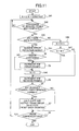
- FIG. 5 illustrates a first example of operation flow of the error rate measuring unit shown in FIG. 4 ;
- FIG. 6 illustrates a first example of operation flow of the target SIR determination unit shown in FIG. 4 ;
- FIG. 7 illustrates a first example of the relation between data transmission timing and target SIR according to an embodiment of the invention
- FIG. 8 illustrates a second example of operation flow of the target SIR determination unit shown in FIG. 4 ;
- FIG. 9 illustrates a relation between the counter value N and the difference ⁇ (N) between the counter value and target SIR
- FIG. 10 illustrates a second example of relation between data transmission timing and target SIR
- FIG. 11 illustrates a second example of operation flow of the error rate measuring unit shown in FIG. 4 ;
- FIG. 12 illustrates a third example of operation flow of the target SIR determination unit shown in FIG. 4 ;
- FIG. 13 illustrates a third example of relation between data transmission timing and target SIR
- FIG. 14 illustrates a relation between data transmission timing and target SIR in which data quality measured in the quality measurement period is reflected
- FIG. 15 illustrates a third example of operation flow of the error rate measuring unit shown in FIG. 4 ;
- FIG. 16 illustrates a major part of the receiving unit taking multiple channels into account to carry out transmit power control
- FIG. 17 illustrates a major part of the transmitting unit taking multiple channels into account to carry out transmit power control
- FIG. 18 illustrates a relation between the target SIR and data transmission conditions of multiple channels.
- FIG. 2 illustrates an example of a radio communications system to which transmit power control of the present invention is applied.
- the radio communications system illustrated in FIG. 2 is a mobile communications system that allows data to be transmitted between the mobile station 100 and the base station 200 .
- the mobile station 100 and the base station 200 transmit and receive data (including packets, control signals, and audio signals) in accordance with, for example, a CDMA scheme.
- the mobile station 100 has a transmitting unit 110 , a receiving unit 120 , a signal processing unit 130 , and a user interface 140 .
- the base station has a transmitting unit 210 , a receiving unit 220 , and a signal processing unit 230 .
- the signal processing unit 130 of the mobile station 100 processes and converts information (such as audio sound, text, images, etc.) input by the user through the user interface 140 into a predetermined format.
- the processed signal is supplied from the signal processing unit 130 to the transmitting unit 110 , in which the signal is encoded and modulated.
- the modulated signal is then transmitted from the transmitting unit 110 to the base station 200 .
- the receiving unit 220 of the base station 200 receives the modulated signal from the mobile station.
- the receiving unit 220 demodulates and decodes the received signal.
- the signal processing unit 230 converts the signal supplied from the receiving unit 220 into an appropriate format so as to be capable of propagating in the network.
- the signal is transmitted from the signal processing unit 230 to the terminating terminal (or the destination terminal) via the network.
- the signal processing unit 230 of the base station 200 processes signals received from the network into a predetermined format.
- the processed signal is supplied to the transmitting unit 210 and subjected to encoding and modulation.
- the modulated signal is transmitted from the transmitting unit 210 to the mobile station 100 .
- the receiving unit 120 of the mobile station 100 receives the modulated signal from the base station 200 , and applies decoding and demodulation to the received signal.
- the signal processing unit 130 converts the decoded and demodulated signal into an appropriate format so as to be treated by the user interface 140 .
- the user interface 140 provides the information (such as audio sound, text, e-mail, images) to the user.
- the transmitting unit 210 of the base station 200 carries out down-link transmit power control based on the transmit power control bit (indicating power up or power down) received from the mobile station 100 .
- the transmitting unit 110 of the mobile station 100 carries out up-link transmit power control based on the transmit power control bit received from the base station 200 .
- FIG. 3 illustrates an example of the structure of the transmitting unit 210 of the base station 200 , which cooperates with the receiving unit 120 of the mobile station 100 to constitute a transmit power control system.
- the transmitting unit 210 includes a radio transmitter 211 , an error detecting encoder 212 , an error correcting encoder 213 , and a transmit power controller 214 .
- Information that is to be transmitted to the destination (mobile station 100 ) is input from the signal processing unit 230 ( FIG. 2 ) to the error detecting encoder 212 .
- the error detecting encoder 212 encodes the data using, for example, CRC (cycle redundancy check), adds a parity bit for error detection to each frame, and outputs this signal to the error correcting encoder 213 .
- the error correcting encoder 213 encodes each frame with a parity bit received from the error detecting encoder 212 .
- the radio transmitter 211 modulates the encoded data of each frame supplied from the error correcting encoder 213 , and transmits the modulated signal.
- the transmit power controller 214 acquires the transmit power control bit, which is generated by the mobile station 100 , from the receiving unit 220 , as will be explained below.
- the transmit power controller 214 regulates the transmit power of the radio transmitter 211 based on the transmit power control bit. For example, if the transmit power control bit represents power up, the transmit power of the radio transmitter 211 is increased by a predetermined quantity (dB). If the transmit power control bit represents power down, then the transmit power is reduced by a predetermined quantity (dB).
- FIG. 4 illustrates an example of the structure of the receiving unit 120 of the mobile station 100 .
- the receiving unit 120 includes a radio receiver 121 , an error correcting decoder/error detector 122 , an error rate measuring unit 123 , a target SIR determination unit 124 , an SIR measuring unit 125 , an SIR comparator 126 , and a transmit power control bit determination unit 127 .
- the radio receiver 121 receives and demodulates a signal transmitted from the base station 200 , and produces a base band signal. The base band signal is supplied to the error correcting decoder/error detector 122 .
- the error correcting decoder/error detector 122 decodes the error correcting code of the base band signal frame by frame, and detects whether there is an error contained in the frame using a CRC technique.
- the decoding result is output from the receiving unit 120 to the signal processing unit 130 (see FIG. 2 ), as indicated by the arrow “data output” in FIG. 4 .
- the error correcting decoder/error detector 122 also outputs an error detection result indicating presence or absence of error for each frame, as well as outputting an idle period detection signal indicating whether it is in an idle period in which information (data and signal) is not transmitted.
- the error rate measuring unit 123 calculates a frame error rate (FER) based on the error detection result supplied from the error correcting decoder/error detector 122 .
- the frame error rate (FER) represents the quality of the information decoded from the received signal (unobstructed or undelayed wave).
- the SIR measuring unit 125 computes an SIR (signal to interference plus noise power ratio) from the received signal supplied from the radio receiver 121 .
- the computation cycle for SIR is shorter than the data frame cycle.
- the target SIR determination unit 124 determines a target SIR so that the data quality (FER) of the received information obtained by the error rate measuring unit 123 approaches the target data quality. The determination process of target SIR will be explained in more detail below.
- the SIR comparator 126 compares the received SIR, which is supplied from the SIR measuring unit 125 , with the target SIR, which is supplied from the target SIR determination unit 124 , and outputs the comparison result.
- the output of the SIR comparator 126 is connected to the input to the transmit power control bit determination unit 127 , which determines the value of the transmit power control bit based on the comparison result. If the received SIR is smaller than the target SIR, the received signal level is low, and therefore, the transmit power control bit is set to a value (“1”, for example) for increasing the transmit power. On the other hand, if the received SIR is greater than the target SIR, the received signal level is high, and therefore, the transmit power control bit is set to a value (“0”, for example) for reducing the transmit power.
- the transmit power control bit generated by the control bit determination unit 127 is supplied to the transmitting unit 110 , which then transmits the transmit power control bit to the base station 200 .
- the transmitting unit 210 of the base station regulates the transmit power based on this transmit power control bit, as has been described above.
- FIG. 5 is a flowchart of calculation of a frame error rate (FER) carried out by the error rate measuring unit 123 .
- the error rate measuring unit 123 determines whether or not the current time belongs to an idle period based on an idle period detection signal (S 1 ). If it is not in the idle period (NO in S 1 ), then it is determined in step S 2 if there is an error detection result input from the error correcting decoder/error detector 122 . If there is no detection result (NO in S 2 ), the error rate measuring unit 123 awaits an error detection result input from the error correcting decoder/error detector 122 . If there is an error detection result (YES in S 2 ), then it is determined if an error is contained (S 3 ).
- S 1 idle period detection signal
- the calculated EFR is output from the error rate measuring unit 123 , and the error frame counter and the received frame counter are reset (S 7 ).
- the error rate measuring unit 123 outputs an FER as a parameter indicating the quality of information restored from the received signal (unobstructed wave).
- the predetermined number is selected based on the target data quality. For example, if the target quality (that is, the target FER) is 10 ⁇ 2 , it is expected that an error frame appears every hundred (100) received frames or more. Accordingly, the predetermined number is set to one hundred (100) or greater.
- an idle period detection signal is input from the error correcting decoder/error detector 122 to the error rate measuring unit 123 (YES in S 1 )
- the error frame counter and the received frame counter are reset (S 9 ).
- the idle period detection signal indicates that it is currently in an idle period in which there are no substantial data being transmitted or received.
- the counters are reset in the idle period in order to prevent an FER from being calculated from the remaining counter values when the data transmission is resumed after the idle period. By resetting the counters, a correct FER (data quality) of the received information can be obtained based on the current environment at the time data transmission is resumed, even if the radio-wave propagation environment has changed during the idle period.
- the operation of the error rate measuring unit 123 shown in FIG. 5 terminates when the communication between the base station 200 and the mobile station 100 is over (NO in S 8 ).
- FIG. 6 illustrates an operation flow of the target SIR determination unit 124 .
- the target SIR determination unit 124 resets the idle flag to zero (0) (S 11 ), and sets the target SIR (SIRt) to the initial value (S 12 ). Then, the target SIR determination unit 124 determines based on the idle period detection signal whether it is in an idle period (S 13 ). If it is not in an idle period (which means that the data are being transmitted), the target SIR determination unit 124 further determines whether the idle flag is set to “1” (S 14 ).
- the target SIR determination unit 124 awaits an FER, which is output from the error rate measuring unit 123 every predetermined number of received frames (NO in S 15 ).
- the input FER exceeds the upper limit (FERt+ ⁇ ) ⁇ ) of the acceptable target error rate (YES in S 19 )
- the input FER does not exceeds the upper limit (FERt+ ⁇ ) of the acceptable target error rate (NO in S 19 )
- a new target SIR is determined every time an FER is input from the error rate measuring unit 123 , based on the relative relation between the input FER and the target frame error rate (FERt). Consequently, during the period in which data are transmitted from the base station 200 to the mobile station 100 (i.e., the period except for idle periods, as illustrated in FIG. 7 ), the target SIR is increased by ⁇ 1 if the data quality obtained from the received information is lower than the target quality (that is, if the input FER exceeds the upper limit of the acceptable range of the target error rate). If the obtained data quality is higher than the target quality (that is, if the input FER is below the lower limit of the acceptable range of the target error rate), the target SIR is decreased by ⁇ 2 . If the obtained data quality is similar to the target quality (that is, if the input FER is within the acceptable range ⁇ of the target error rate), the current target SIR is maintained.
- the transmit power of the transmitting station e.g., the transmitting unit of the base station
- the transmit power of the transmitting station is efficiently regulated so that the data quality of the information received at the receiving station (e.g., the mobile station) approaches the target quality.
- the unit ⁇ 1 for increasing the target SIR may be equal to or different from the unit ⁇ 2 for decreasing the target SIR.
- Setting ⁇ 1 greater than ⁇ 2 is preferable when the received data quality is lower than the target quality because transmit power control is carried out so that the received data can promptly converge to the target quality.
- the foregoing operation is directed to the process during data transmission between the base station 200 and the mobile station 100 . Then, if the data transmission from the base station 200 to the mobile station 100 pauses and an idle period ensues, the target SIR determination unit 124 determines in step S 13 that it is in an idle period based on an idle period detection signal (YES in S 13 ). In this case, the process proceeds to step S 14 to determine whether the idle flag is set to “1”. If the idle flag is not set (NO in S 24 ), the idle flag is set to “1” (S 25 ). The confirmation whether the idle flag is set to “1” is repeated until the data transmission starts again (S 13 and S 24 ).
- the target SIR determination unit 124 again determines based on the idle period detection signal that it is not in the idle period (NO in S 13 ), and checks if the idle flag is set to “1” (S 14 ).
- the state of the idle flag is maintained at “1”, as has been set at the beginning of the idle period (i.e., at t e1 and t e2 ). Accordingly, the determination result in step S 14 indicates that the idle flag is set to “1” (YES in S 14 ).
- FERt target frame error rate
- FIG. 7 illustrates a first example of a relation between target SIR and data transmission state.
- the target SIRto set at t s1 and t s2 i.e., at the beginning of the data transmission period immediately after the idle period
- transmit power is regulated so that the measured SIR of the received signal approaches the relatively high target SIRto in a certain period beginning from t s1 and t s2 .
- the data quality obtained at the mobile station 100 can be maintained high (which means that the frame error rate of the received signal is maintained small) even if the radio-wave propagation environment has changed during the idle period.
- SIRto set at the beginning of the data transmission is not limited to the upper limit or its vicinity of the acceptable range of the target SIR.
- a predetermined quantity may be added to the target SIR updated at t e1 and t e2 (which is at the end of the previous data transmission period, or the beginning of the idle period) when the data transmission resumes at t s1 and t s2 .
- the updated SIRto may be slightly lower than the appropriate target SIR expected from the current radio-wave propagation environment between the base station 200 and the mobile station 100 depending on the situation.
- the newly set SIRto can converge much rapidly to the appropriate target SIR, following steps S 13 through S 22 , as compared with the conventional technique for resuming regulation of the target SIR from the latest target SIR obtained at the end of the previous data transmission period (or the beginning of the idle period).
- the operation for setting the target SIR (S 13 -S 27 is carried out repeatedly depending on the situation as long as communications continues between the mobile station 100 and the base station 200 (YES in S 23 ).
- communications between the mobile station 100 and the base station 200 terminates (NO in S 23 )
- the process also terminates.
- FIG. 8 illustrates a second example of operation flow carried out by the target SIR determination unit 124 .
- the level of SIRto updated at the beginning of the data transmission immediately after the idle period is adjusted in accordance with the length of the idle period.
- the same numerical symbols denote the same steps as those shown in FIG. 6 .
- the target SIR determination unit 124 determines an appropriate target SIR based on the relative relation between the input (measured) FER and the target error rate FERt (S 15 -S 22 ) every time it receives a measured FER input from the error rate measuring unit 123 , as in the example shown in FIG. 6 .
- the target SIR determination unit 124 determines based on the idle period detection signal that it is in the idle period (YES in S 13 ). Then, timer process for timing a predetermined time is started (S 33 ), and the counter value N is incremented by +1 when the time is up (S 34 ). The timing (S 33 ) and the increment (S 34 ) are repeated during the idle period (YES in S 13 ), and the counter value N is incremented one by one every predetermined time interval.
- the target SIR determination unit 124 determines based on the idle period detection signal that it is not in the idle period (NO in S 13 ). Then, it is further determined whether the counter value N is zero (S 32 ). Immediately after the idle period, the counter indicates a value corresponding to the length of the idle period because the counter value N has been incremented every predetermined time. Therefore, the determination result in S 32 becomes negative (NO in S 32 ).
- FIG. 9 illustrates an example of relation between counter value N and difference ⁇ (N) defined in the table.
- the difference ⁇ (N) increases stepwise.
- FIG. 10 illustrates a second example of relation between the target SIR and data transmission state.
- difference ⁇ (N 2 ) added at time t s2 after a longer idle period T N2 is greater than difference ⁇ (N 1 ) added at t s1 after a shorter idle period T N1 .
- how much difference is added to the latest target SIR obtained at the end of the previous data transmission (at t e1 or t e2 ) is determined based on the length of the most recent idle period.
- a relatively large target SIR is set at time t s2 after the idle period T N2 , and transmit power is regulated for a certain time period beginning from t s2 so that the received SIR approaches the relatively large target SIR.
- This arrangement allows the data quality obtained at the mobile station 100 to be maintained relatively high, with a relatively small error rate.
- FIG. 11 illustrates a second example of operation flow carried out by the error rate measuring unit 123 .
- a pseudo-FER is generated by the error rate measuring unit 123 during the idle period.
- Such pseudo-FER allows the target SIR determination unit 124 to set a relatively large target SIR, without monitoring the idle period, when data transmission resumes immediately after the idle period.
- the same numerical symbols denote the same steps as those shown in FIG. 5 .
- the error rate measuring unit 123 sets the counter value N to zero (i.e., the initial value), and selects a constant M (S 41 ).
- the error rate measuring unit 123 checks whether the error correcting decoder/error detector 122 has completed processing (including decoding and error detection) of received frames (S 42 ). If the signal processing of the received frames has been completed by the error correcting decoder/error detector 122 (YES in S 42 ), then it is determined whether there are data received at the mobile station based on the idle period detection signal (S 43 ). If there are received data, which means that is it is not in the idle period (YES in S 43 ), then the error rate measuring unit 123 acquires the error detection result from the error correcting decoder/error detector 122 (S 44 ).
- the error frame counter and the received frame counter are incremented (S 4 and S 5 ), as in the first example of FIG. 5 . If the detection result indicates that no error is contained in the frame (NO in S 3 ), then only the error frame counter is incremented (S 5 ). Every time error frame counter is incremented, the above-mentioned counter value N is reset (S 45 ).
- the error rate measuring unit 123 acquires an error detection result every time completion of the received frame processing has been confirmed (S 42 -S 44 ). Based on the detection result, incrementing the error frame counter and the received frame counter, while resetting the counter value N, are repeated (S 3 , S 4 , S 45 , and S 5 ).
- a frame error rate (FER) is calculated based on the current number of received frames and the number of error frames, and the calculated EFR is output (S 7 ), as in FIG. 5 . Then, the respective counters are reset.
- the error rate measuring unit 123 supplies an EFR to the target SIR determination unit 124 every time the number of received frames reaches the predetermined value as long as data is being transmitted from the base station 200 to the mobile station 100 .
- the counter value N is incremented by +1 (S 46 ), and it is determined if the counter value N has reached the constant M (S 47 ).
- the constant M is used in order to produce a pseudo-FER, and is set smaller than the above-described “predetermined value” used in determination step S 6 . If the counter value N has not reaches the constant M (NO in S 47 ), the number of received frames is simply incremented (S 5 ).
- the error rate measuring unit 123 repeats the above-described steps S 42 , S 43 , S 46 , S 47 , S 4 , S 45 , S 5 , S 6 and S 7 , and produces a pseudo-FER every M time frames.
- This pseudo-FER corresponds to a ratio of a single error frame to M received frames.
- the constant M is selected so that the pseudo-FER becomes larger than the upper limit (FERt+ ⁇ ) of the acceptable target error rate used to determine a target SIR.
- the target SIR determination unit 124 receives an FER, which is output from the error rate measuring unit 123 based on the actual number of error frames during the data transmission from the base station 200 to the mobile station 100 , and a pseudo-FER, which is output from the error rate measuring unit 123 during the idle period.
- FIG. 12 illustrates a third example of operation flow of the target SIR determination unit 124 configured to cope with the pseudo-FER input from the error rate measuring unit 123 .
- the same numerical symbols denote the same steps as those shown in FIG. 6 (i.e., the first example of operation flow of the target SIR determination unit 124 ).
- a target SIR is determines based on the relative relation between a measured FER and a target frame error rate (FERt) every time the measured FER is input from the error rate measuring unit 123 .
- FERt target frame error rate
- a pseudo-FER is output from the error rate measuring unit 123 , as has been explained above in conjunction with FIG. 11 .
- the pseudo-FER exceeds the upper limit of the acceptable target FER because the constant M is selected so that the pseudo-FER is greater than FERt+ ⁇ in S 41 of FIG. 11 .
- the target SIR is increased by ⁇ 1 (S 15 , S 16 , S 19 , and S 20 ).
- the target SIR is increase by ⁇ 1 every time the pseudo-FER is input during the idle period. Consequently, the difference between the target SIR at the beginning of the idle period and that at the end of the idle period becomes larger as the idle period is longer, as in the previous example explained in conjunction with FIGS. 8 , 9 , and 10 .
- FIG. 13 illustrates the relation between the target SIR and the data transmission state.
- the longer the idle period the greater a change in radio-wave propagation environment.
- a relatively large SIR is set immediately after a relatively long idle period, and transmit power is regulated for a certain period of time from the beginning of data transmission, so that the received SIR approaches the relatively large target SIR.
- the change in radio-wave propagation environment is not significant if the idle period is short, and accordingly, the increase in the target SIR is not so large.
- This arrangement can guarantee a sufficiently high target SIR after a long idle period, while preventing the target SIR from being set unnecessarily high after a short idle time.
- the target SIR determination unit 124 does not have to recognize idle periods. Consequently, the operation flow for determining a target SIR becomes simpler.
- FIG. 14 illustrates still another example in which data quality information is reflected to the target SIR.
- a pseudo-FER is calculated every predetermined number of time frames corresponding to the data-quality measuring period (indicated by the bidirectional arrow) during the idle period.
- the calculated FER is reflected to the target SIR at the rising edge of the steps shown in FIG. 14 . If data transmission starts again halfway through the data-quality measuring period, the number of pseudo-error frames counted so far is added to the actual error rate calculated from actually received data immediately after time ts (at the beginning of data transmission period). In this case, an unnecessarily high target SIR may be set as indicated in the dashed step. This may cause the accuracy of FER to deteriorate immediately after ts (starting time of a data transmission period).
- the error rate measuring unit 123 carries out the operation shown in FIG. 15 .
- FIG. 15 illustrates a third example of operation flow carried out by the error rate measuring unit 123 .
- the error rate measuring unit 123 calculates an FER based on the actually received data beginning from time ts immediately after the idle period.
- the same numerical symbols denote the same steps as those shown in FIG. 11 .
- the error frame counter counts up at a ratio of a signal error frame to M time frames, while making confirmation of the idle flag being set up (S 46 , S 47 , S 47 S 45 , and S 5 ). Every time the number of time frames reaches a predetermined value, pseudo-FER is calculated and output (S 7 ).
- the error frame counter and the received frame counter are reset every time data transmission resumes immediately after the idle period. Consequently, an accurate frame error rate reflecting only the actually received data is obtained, without taking the pseudo-FER into account at the beginning of resumed data transmission.
- This arrangement allows the target SIR to be determined more accurately even immediately after the idle period.
- FIG. 16 illustrates an example of the structure of the receiving unit 120 suitable to multi-channel communications.
- the radio receiver 121 receives a multiplexed signal of channel 1 (data channel, for example) and channel 2 (control channel, for example).
- Signal separation circuit 128 separates the signal components into channel 1 and channel 2 .
- An error correcting decoder/error detector 122 a and an error rate measuring unit 123 a are provided for channel 1 .
- an error correcting decoder/error detector 122 b and an error rate measuring unit 123 b are provided for channel 2 .
- the target SIR determination unit 124 receives data quality information (FER) about channel 1 and channel 2 from the error rate measuring units 123 a and 123 b , respectively. Based on the received data qualities of the respective channels, a target SIR is to be determined.
- FER data quality information
- SIR comparator 126 compares the measured SIR obtained at SIR measuring unit 125 with the target SIR determined by the target SIR determination unit 124 . Based on the comparison result, the transmit power control bit determination unit 127 determines a value of the transmit power control bit.
- FIG. 17 illustrates an example of the structure of transmitting unit 210 that corresponds to the receiving unit 120 dealing with multi-channel communications.
- the transmitting unit 210 has an error detecting encoder 212 a and an error correcting encoder 213 a for channel 1 , and has an error detecting encoder 212 b and an error correcting encoder 213 b for channel 2 .
- the signals from the error correcting encoders 213 a and 213 b are multiplexed at the multiplexer 215 , which is then supplied to the radio transmitter 211 .
- the radio transmitter 211 modulates the multiplexed signal to transmit the signal to the mobile station 100 .
- the transmit power controller 214 regulates the transmit power of the radio transmitter 211 based on the transmit power control bit received from the mobile station 100 .
- FIG. 18 illustrates an example of setting a target SIR in multi-channel communications. If there are two channels, data (or control signals) are transmitted discontinuously at each channel. There are several situations.
- the target SIR determination unit 124 determines a target SIR( 1 ) for channel 1 based on the relative relation between the measured data quality (FER) received from the error rate measuring unit 123 a and the target data quality for channel 1 (according to the operation flow shown in FIG. 12 ). Similarly, a target SIR( 2 ) for channel 2 is determined based on the relative relation between the measured data quality (FER) obtained at the error rate measuring unit 123 b and the target data quality for channel 2 . Between target SIR( 1 ) and target SIR( 2 ), the larger one is selected as the final target SIR.
- FER measured data quality
- a target SIR is determined based on the relative relation between the measured data quality (FER) received from either the error rate measuring unit 123 a or 123 b and the target data quality of that channel, according to the operation flow shown in FIG. 12 .
- FER measured data quality
- the target SIR is set to SIRtx.
- SIRtx may be updated at or near the upper limit SIRto of the acceptable control range of the target SIR as shown in FIG. 6 , or alternatively, it may be updated by adding a difference ⁇ corresponding to the length of the latest idle period to the previous target SIR as illustrated in FIGS. 8 through 13 .
- the transmitting station is, for example, a base station 200 of a mobile communications system, and the receiving station-corresponds to a mobile station.
- Step 26 in FIG. 6 (setting target SIR to predetermined SIRto immediately after the idle period), step 35 in FIG. 8 (setting target SIR to SIRt+ ⁇ (N) taking the length of the idle period into account), and step 20 in FIG. 12 (setting target SIR to SIRt+ ⁇ 1 or SIRt ⁇ 2 when using a pseudo-FER) are referred to as setting or adjusting a target signal quality.
- the target SIR is appropriately updated when data transmission resumes immediately after the idle period, which is relatively large as compared with the target SIR set at the beginning of the idle period. Consequently, data transmission resumes at a relatively high transmit power without causing deterioration of data quality even if the radio-wave propagation environment has changed between the transmitting station and the receiving station during the idle period.
- data quality information may not be limited to the current frame error rate (FER) calculated each time an error detection result is input. Instead, a moving average of FER obtained at a prescribed cycle may be used as data quality information.
- FER current frame error rate
- the target SIR determination unit 124 may determine a target SIR based directly on the error detection result supplied from the error correcting decoder/error detector 122 , instead of using an FER supplied from the error rate measuring unit 123 . In this case, if the error detection result of each frame or every predetermined number of frames indicates the presence of error, the target SIR is increased by a predetermined quantity (1 dB, for example). If the error detection result indicates no error contained in successive frames, the target SIR may be decreased by a predetermined quantity (0.5 dB, for example).
Abstract
A transmit power control method and system used in radio communications between a transmitting station and a receiving station is provided. The method and system employ a so-called double closed-loop control technique, and target signal quality is updated so that data quality received at the receiving station satisfies prescribed target data quality. When data are transmitted discontinuously, first target signal quality updated immediately before an idle period is held, and second target signal quality higher than the first target signal quality is set when data transmission resumes immediately after the idle period. The transmit power of the transmitting station is regulated so that signal quality at the receiving station satisfies the second target signal quality when the data transmission resumes.
Description
1. Field of the Invention
The present invention relates to a transmit power control method and system employing a so-called double closed-loop control, which is suitably used in radio communications between a transmitting station and a receiving station.
2. Description of Related Art
Conventionally, transmit power control techniques have been employed in mobile communications. For example, International Publication WO97/50197 discloses double closed-loop control for regulating the transmit power of a transmitting station (either the base station or a mobile terminal) during radio communications between the base station and the mobile terminal in a CDMA mobile communications system. Double closed-loop control consists of inner-loop control and outer-loop control. Under inner-loop control, the transmit power of the transmitting station is regulated so that the SIR (Signal to Interference plus noise power Ratio) measured at the receiving station approaches a target SIR. During this process, data quality (frame error rate (FER) or bit error rata (BER), for example) of the received information is monitored at the receiving station, and the target SIR itself is updated so that the received data quality approaches the target quality (that is, outer-loop control).
With this double closed-loop control, transmit power control is performed efficiently during continuous data transmission between the transmitting station and the receiving station, while the signal quality received at the receiving station is maintained at a desired level (or the target quality).
However, if discontinuous transmission is performed between the transmitting station and the receiving station (for example, in burst mode, packet transmission, or transmitting control signals), problems arise in the conventional double closed-loop control.
Under this situation, if the target SIR at the end of the previous transmission (at time te) is maintained until the beginning of the next transmission (time ts), that target SIR may be much lower than the correct target SIR (indicated by the dashed line in FIG. 1 ) that should be obtained based on the data receiving quality expected from the current environment of radio wave propagation in the idle period. For this reason, when the data transmission is resumed at ts, it takes time for the target SIR to converge to the correct level obtained by the outer-loop control. During the time delay required for the convergence, the data receiving quality inevitably deteriorates.
Therefore, it is an object of the invention to provide a transmit power control method and system employing double closed-loop control, which is suitable for discontinuous transmission and capable of reducing deterioration of data receiving quality at the beginning of data transmission.
To achieve the object, in one aspect of the invention, a transmit power control method used in radio communications between a transmitting station and a receiving station is provided. This method employs a so-called double closed-loop control technique, and target signal quality is updated so that data quality received at the receiving station satisfies prescribed target data quality. When data is transmitted discontinuously, first target signal quality updated immediately before an idle period is held, and second target signal quality higher than the first target signal quality is set when data transmission resumes immediately after the idle period. Transmit power of the transmitting station is regulated so that signal quality at the receiving station satisfies the second target signal quality when the data transmission resumes.
With this method, when data transmission has resumed after the idle period, the transmit power of the transmitting station is regulated so that signal quality at the receiving station approaches a relatively high signal quality. Since data is transmitted from the transmitting station at a relatively higher transmit power when data transmission has resumed, deterioration of data quality immediately after the idle period can be efficiently prevented.
Signal quality can be expressed by, for example, a received signal level or a signal to interference plus noise power ratio (SIR), but is not limited to these examples.
Data quality can be expressed by, for example, a frame error rate (FER), a bit error rate (BER), moving average of FER or BER, or presence or absence of error per data transmission unit (such as frame), but is not limited to these examples. Any type of data quality can be used as long as it indicates the degree of consistency between the original data transmitted by the transmitting station and the received data at the receiving station.
The second target signal quality may be fixed at or near the upper limit of the acceptable range of target signal quality. Alternatively, it may be adjusted depending on the conditions, such as the radio-wave propagation environment between the transmitting station and the receiving station.
In the latter case, the radio-wave propagation environment changes depending on how long the idle period continues. In this case, the second target signal quality is adjusted in response to the length of the idle period. For example, the second target signal quality is set by adding a differential quantity corresponding to the length of the idle period to the first target signal quality.
The target signal quality may be adjusted without recognizing the idle period. In this case, pseudo data quality that is lower than the prescribed target data quality is produced during the idle period. The target signal quality during the idle period is updated based on the pseudo data quality.
In order to obtain the target signal quality more accurately, while applying the algorithm for obtaining the data quality as it is to the generation of pseudo data quality, the second target signal quality is set without taking the latest pseudo data quality into account when the data transmission resumes immediately after the idle period.
In order to prevent the data quality from becoming unnecessarily high and to achieve reasonable transmit power control, the second target signal quality is set so as not to exceed a predetermined upper limit.
The above-described method is applicable to multi-channel radio communications. In this case, the second target signal quality is set when data transmission resumes on at least one of multiple channels under a situation where all the channels have been in the idle period. The second target signal quality is updated so as to be higher than the first target signal quality of that channel.
The target signal quality is updated so that the data quality of each channel satisfies the corresponding target data quality assigned to that channel.
In another aspect of the invention, a transmit power control system used for radio communications between a transmitting station and a receiving station is provided. This system comprises a target signal quality determination unit for setting target signal quality so that data quality received at the receiving station satisfies a prescribed target data quality. The target signal quality determination unit holds first target signal quality updated immediately before an idle period when data are transmitted discontinuously, and it sets second target signal quality that is higher than the first target signal quality when data transmission resumes immediately after the idle period. The system also comprises a control signal generator that generates a transmit power control signal based on the target signal quality, and a transmit power controller that regulates the transmit power of the transmitting station based on the control signal so that signal quality of the receiving station satisfies the target signal quality.
Other objects, features, and advantages of the invention will become more apparent from the following detailed description when read in conjunction with the accompanying drawings, in which
The details of the preferred embodiments of the invention will now be described with reference to the attached drawings.
The mobile station 100 and the base station 200 transmit and receive data (including packets, control signals, and audio signals) in accordance with, for example, a CDMA scheme. The mobile station 100 has a transmitting unit 110, a receiving unit 120, a signal processing unit 130, and a user interface 140. The base station has a transmitting unit 210, a receiving unit 220, and a signal processing unit 230.
The signal processing unit 130 of the mobile station 100 processes and converts information (such as audio sound, text, images, etc.) input by the user through the user interface 140 into a predetermined format. The processed signal is supplied from the signal processing unit 130 to the transmitting unit 110, in which the signal is encoded and modulated. The modulated signal is then transmitted from the transmitting unit 110 to the base station 200.
The receiving unit 220 of the base station 200 receives the modulated signal from the mobile station. The receiving unit 220 demodulates and decodes the received signal. The signal processing unit 230 converts the signal supplied from the receiving unit 220 into an appropriate format so as to be capable of propagating in the network. The signal is transmitted from the signal processing unit 230 to the terminating terminal (or the destination terminal) via the network.
When receiving signals, the signal processing unit 230 of the base station 200 processes signals received from the network into a predetermined format. The processed signal is supplied to the transmitting unit 210 and subjected to encoding and modulation. The modulated signal is transmitted from the transmitting unit 210 to the mobile station 100.
The receiving unit 120 of the mobile station 100 receives the modulated signal from the base station 200, and applies decoding and demodulation to the received signal. The signal processing unit 130 converts the decoded and demodulated signal into an appropriate format so as to be treated by the user interface 140. The user interface 140 provides the information (such as audio sound, text, e-mail, images) to the user.
The transmitting unit 210 of the base station 200 carries out down-link transmit power control based on the transmit power control bit (indicating power up or power down) received from the mobile station 100. Similarly, the transmitting unit 110 of the mobile station 100 carries out up-link transmit power control based on the transmit power control bit received from the base station 200.
The radio transmitter 211 modulates the encoded data of each frame supplied from the error correcting encoder 213, and transmits the modulated signal. The transmit power controller 214 acquires the transmit power control bit, which is generated by the mobile station 100, from the receiving unit 220, as will be explained below. The transmit power controller 214 regulates the transmit power of the radio transmitter 211 based on the transmit power control bit. For example, if the transmit power control bit represents power up, the transmit power of the radio transmitter 211 is increased by a predetermined quantity (dB). If the transmit power control bit represents power down, then the transmit power is reduced by a predetermined quantity (dB).
The error rate measuring unit 123 calculates a frame error rate (FER) based on the error detection result supplied from the error correcting decoder/error detector 122. The frame error rate (FER) represents the quality of the information decoded from the received signal (unobstructed or undelayed wave).
The SIR measuring unit 125 computes an SIR (signal to interference plus noise power ratio) from the received signal supplied from the radio receiver 121. The computation cycle for SIR is shorter than the data frame cycle. The target SIR determination unit 124 determines a target SIR so that the data quality (FER) of the received information obtained by the error rate measuring unit 123 approaches the target data quality. The determination process of target SIR will be explained in more detail below. The SIR comparator 126 compares the received SIR, which is supplied from the SIR measuring unit 125, with the target SIR, which is supplied from the target SIR determination unit 124, and outputs the comparison result.
The output of the SIR comparator 126 is connected to the input to the transmit power control bit determination unit 127, which determines the value of the transmit power control bit based on the comparison result. If the received SIR is smaller than the target SIR, the received signal level is low, and therefore, the transmit power control bit is set to a value (“1”, for example) for increasing the transmit power. On the other hand, if the received SIR is greater than the target SIR, the received signal level is high, and therefore, the transmit power control bit is set to a value (“0”, for example) for reducing the transmit power. The transmit power control bit generated by the control bit determination unit 127 is supplied to the transmitting unit 110, which then transmits the transmit power control bit to the base station 200. The transmitting unit 210 of the base station regulates the transmit power based on this transmit power control bit, as has been described above.
Then, it is determined if the number of received frames has reached a predetermined number (S6). If the number of received frames has not reached the predetermined number (NO in S6), it is confirmed if the data are being transmitted (S8), and if YES in S8, the above-described steps S1 through S6 are repeated. In this manner, during data transmission between the base station 200 and the mobile station 100 (that is, not in an idle period), every time the error detection result indicating the presence of error is input (YES in S2 and S3), both counters for the number of error frames and for the number of received frames are incremented (S4 and S5). If the error detection result indicates no error contained in the frame (NO in S3), only the counter for the number of received signal is incremented (S5).
If the number of received frames has reached the predetermined number (YES in S6) after repeating steps S1-S6 and S8, a frame error rate (FER=ratio of the number of error frames to the number of received frames) is calculated from the currently obtained received frames and the error frames (S7). The calculated EFR is output from the error rate measuring unit 123, and the error frame counter and the received frame counter are reset (S7). As long as data are being transmitted from the base station 200 to the mobile station 100 (NO in S1), the above-described operation process is executed repeatedly. Every time the number of received frame has reached the predetermined number, the error rate measuring unit 123 outputs an FER as a parameter indicating the quality of information restored from the received signal (unobstructed wave).
The predetermined number is selected based on the target data quality. For example, if the target quality (that is, the target FER) is 10−2, it is expected that an error frame appears every hundred (100) received frames or more. Accordingly, the predetermined number is set to one hundred (100) or greater.
During the above-described operation, if an idle period detection signal is input from the error correcting decoder/error detector 122 to the error rate measuring unit 123 (YES in S1), the error frame counter and the received frame counter are reset (S9). The idle period detection signal indicates that it is currently in an idle period in which there are no substantial data being transmitted or received. The counters are reset in the idle period in order to prevent an FER from being calculated from the remaining counter values when the data transmission is resumed after the idle period. By resetting the counters, a correct FER (data quality) of the received information can be obtained based on the current environment at the time data transmission is resumed, even if the radio-wave propagation environment has changed during the idle period.
The operation of the error rate measuring unit 123 shown in FIG. 5 terminates when the communication between the base station 200 and the mobile station 100 is over (NO in S8).
If an FER is input from the error rate measuring unit 123 (YES in S15), the input FER is compared with the target FER (FERt) indicating the target data quality (S16). Based on the comparison result, it is determined whether the input FER is within the rage of plus or minus α of the target FER (FERt±α) (S17). If the input FER is within the range FERt±α (YES in S17), the currently updated target SIR (SIRt) is maintained (SIRt=SIRt) (S18). On the other hand, the input FER is not within the range FERt±α (NO in S17), it is further determined if the input FER exceeds the upper limit (FERt+α) of the acceptable target error rate (S19).
If the input FER exceeds the upper limit (FERt+α) α) of the acceptable target error rate (YES in S19), the data quality of the received information does not reach the target data quality, and therefore, the target SIR (SIRt) is increased by Δ1 (SIRt=SIRt+Δ1) in step S20. On the other hand, if the input FER does not exceeds the upper limit (FERt+α) of the acceptable target error rate (NO in S19), it is further determined if the input FER is below the lower limit (FERt−α) of the acceptable target error rate (S21). If the input FER is below the lower limit (FERt−α) of the acceptable target error rate (YES in S21), the data quality of the received information reaches the target quality, and therefore, the target SIR (SIRt) is decreased by Δ2 (SIRt=SIRt−Δ2) in step S22.
If the input FER is not below the lower limit (FERt−α) of the acceptable target error rate (NO in S21), this determination result is inconsistent with the foregoing determinations (NO in S17 and S19). Therefore, the currently updated target SIR is maintained (SIRt=SIRt) in step S18.
In this manner, a new target SIR is determined every time an FER is input from the error rate measuring unit 123, based on the relative relation between the input FER and the target frame error rate (FERt). Consequently, during the period in which data are transmitted from the base station 200 to the mobile station 100 (i.e., the period except for idle periods, as illustrated in FIG. 7), the target SIR is increased by Δ1 if the data quality obtained from the received information is lower than the target quality (that is, if the input FER exceeds the upper limit of the acceptable range of the target error rate). If the obtained data quality is higher than the target quality (that is, if the input FER is below the lower limit of the acceptable range of the target error rate), the target SIR is decreased by Δ2. If the obtained data quality is similar to the target quality (that is, if the input FER is within the acceptable range ±α of the target error rate), the current target SIR is maintained.
Regulating the target SIR so that the measured data quality approaches the target quality is the outer loop control. Determining the transmit power control bit so that the SIR of the received signal approaches the target SIR is the inner loop control. With this double closed-loop control, the transmit power of the transmitting station (e.g., the transmitting unit of the base station) is efficiently regulated so that the data quality of the information received at the receiving station (e.g., the mobile station) approaches the target quality.
The unit Δ1 for increasing the target SIR may be equal to or different from the unit Δ2 for decreasing the target SIR. Setting Δ1 greater than Δ2 is preferable when the received data quality is lower than the target quality because transmit power control is carried out so that the received data can promptly converge to the target quality.
The foregoing operation is directed to the process during data transmission between the base station 200 and the mobile station 100. Then, if the data transmission from the base station 200 to the mobile station 100 pauses and an idle period ensues, the target SIR determination unit 124 determines in step S13 that it is in an idle period based on an idle period detection signal (YES in S13). In this case, the process proceeds to step S14 to determine whether the idle flag is set to “1”. If the idle flag is not set (NO in S24), the idle flag is set to “1” (S25). The confirmation whether the idle flag is set to “1” is repeated until the data transmission starts again (S13 and S24).
If data transmission from the base station 200 resumes, the target SIR determination unit 124 again determines based on the idle period detection signal that it is not in the idle period (NO in S13), and checks if the idle flag is set to “1” (S14). At the beginning of the data transmission immediately after the idle period (that is, at time ts1 and ts2 shown in FIG. 7), the state of the idle flag is maintained at “1”, as has been set at the beginning of the idle period (i.e., at te1 and te2). Accordingly, the determination result in step S14 indicates that the idle flag is set to “1” (YES in S14). In this case, the process proceeds to step S26, and the target SIR is set to a predetermined vale SIRto (SITt=SITto). Then, the idle flag is reset to “0” (S27). Subsequently, the steps S13 through S22 are repeated as long as data are transmitted from the base station 200 to the mobile station 100 to determine an appropriate target SIR based on the relative relation between the measured FER and the target frame error rate (FERt).
Of course, SIRto set at the beginning of the data transmission is not limited to the upper limit or its vicinity of the acceptable range of the target SIR. For example, a predetermined quantity may be added to the target SIR updated at te1 and te2 (which is at the end of the previous data transmission period, or the beginning of the idle period) when the data transmission resumes at ts1 and ts2. In this case, the updated SIRto may be slightly lower than the appropriate target SIR expected from the current radio-wave propagation environment between the base station 200 and the mobile station 100 depending on the situation. However, the newly set SIRto can converge much rapidly to the appropriate target SIR, following steps S13 through S22, as compared with the conventional technique for resuming regulation of the target SIR from the latest target SIR obtained at the end of the previous data transmission period (or the beginning of the idle period).
The operation for setting the target SIR (S13-S27 is carried out repeatedly depending on the situation as long as communications continues between the mobile station 100 and the base station 200 (YES in S23). When communications between the mobile station 100 and the base station 200 terminates (NO in S23), the process also terminates.
In operation, the counter value N is set to the initial value “0” (N=0), and the target SIR (SIRt) is set to the initial value (S31 and S12). Then, the target SIR determination unit 124 determines based on the idle period detection signal whether it is in an idle period (S13). If not in an idle period (that is, it is in a data transmission period), then it is determined whether the counter value N is zero (S32). If the counter value N is zero in the data transmission period (NO in S13 and YES in S32), then, the target SIR determination unit 124 determines an appropriate target SIR based on the relative relation between the input (measured) FER and the target error rate FERt (S15-S22) every time it receives a measured FER input from the error rate measuring unit 123, as in the example shown in FIG. 6.
When the data transmission from the base station 200 pauses and the idle period resumes during the above-described operation, the target SIR determination unit 124 determines based on the idle period detection signal that it is in the idle period (YES in S13). Then, timer process for timing a predetermined time is started (S33), and the counter value N is incremented by +1 when the time is up (S34). The timing (S33) and the increment (S34) are repeated during the idle period (YES in S13), and the counter value N is incremented one by one every predetermined time interval.
When the data transmission from the base station starts again, the target SIR determination unit 124 determines based on the idle period detection signal that it is not in the idle period (NO in S13). Then, it is further determined whether the counter value N is zero (S32). Immediately after the idle period, the counter indicates a value corresponding to the length of the idle period because the counter value N has been incremented every predetermined time. Therefore, the determination result in S32 becomes negative (NO in S32).
Then, the process proceeds to step S35, and a new target SIR is obtained by adding a difference Δ(N) that corresponds to the current counter value N to the latest target SIR maintained during the idle period (SIRt=SIRt+Δ(N)), with reference to a table defining a relation between counter value N and difference Δ(N). Then, the counter value N is reset to zero (S36). After resetting the counter, the above-described steps S15 through S22 are repeated to determine an update target SIR, based on the relative relation between the measured FER and the target error rate FERt, as long as data are transmitted from the base station 200.
It is generally expected that, after a relatively long idle time TN2, change in the radio-wave propagation environment is relatively large. Therefore, a relatively large target SIR is set at time ts2 after the idle period TN2, and transmit power is regulated for a certain time period beginning from ts2 so that the received SIR approaches the relatively large target SIR. This arrangement allows the data quality obtained at the mobile station 100 to be maintained relatively high, with a relatively small error rate.
Similarly, change in the radio-wave propagation environment is likely to be small after a relatively short idle period TN1, and therefore, increase in the target SIR at time ts1 is expected to be relatively small. By setting a smaller difference Δ(N), the target SIR is updated to an appropriate level, preventing the situation where the target SIR is set unnecessarily high. Consequently, transmit power is regulated so that data quality obtained at the mobile station 100 becomes uniform without using excessive transmit power (and therefore without causing localized excessive quality).
In operation, the error rate measuring unit 123 sets the counter value N to zero (i.e., the initial value), and selects a constant M (S41). The error rate measuring unit 123 checks whether the error correcting decoder/error detector 122 has completed processing (including decoding and error detection) of received frames (S42). If the signal processing of the received frames has been completed by the error correcting decoder/error detector 122 (YES in S42), then it is determined whether there are data received at the mobile station based on the idle period detection signal (S43). If there are received data, which means that is it is not in the idle period (YES in S43), then the error rate measuring unit 123 acquires the error detection result from the error correcting decoder/error detector 122 (S44).
Then, every time the acquired error detection result indicates the presence of error (YES in S3), the error frame counter and the received frame counter are incremented (S4 and S5), as in the first example of FIG. 5. If the detection result indicates that no error is contained in the frame (NO in S3), then only the error frame counter is incremented (S5). Every time error frame counter is incremented, the above-mentioned counter value N is reset (S45).
During data transmission from the base station 200 to the mobile station 100 (YES in S43), the error rate measuring unit 123 acquires an error detection result every time completion of the received frame processing has been confirmed (S42-S44). Based on the detection result, incrementing the error frame counter and the received frame counter, while resetting the counter value N, are repeated (S3, S4, S45, and S5). When the number of received frames has reached a predetermined value (YES in S6), a frame error rate (FER) is calculated based on the current number of received frames and the number of error frames, and the calculated EFR is output (S7), as in FIG. 5. Then, the respective counters are reset.
In this manner, the error rate measuring unit 123 supplies an EFR to the target SIR determination unit 124 every time the number of received frames reaches the predetermined value as long as data is being transmitted from the base station 200 to the mobile station 100.
When the current data transmission period terminates, it is determined based on the idle period detection signal that it is in the idle period without any data received from the base station (NO in S43). Then the counter value N is incremented by +1 (S46), and it is determined if the counter value N has reached the constant M (S47). The constant M is used in order to produce a pseudo-FER, and is set smaller than the above-described “predetermined value” used in determination step S6. If the counter value N has not reaches the constant M (NO in S47), the number of received frames is simply incremented (S5). As long as the idle period continues (NO in S43), incrementing of counter value N (S46), comparison of N with M (S47), incrementing of the received frame counter (S5), and comparison of the number of received frames with the predetermined value (S6) are repeated every time signal processing of the received frame has been completed (YES in S42).
During this process, if the counter value N has reaches the constant M (YES in S47), then the error frame counter is incremented (S4), and the counter value N is reset to zero (S45). Every time the number of received frames reaches the constant M, the error frame counter is incremented. Then, if the number of received frames has reached the predetermined value (YES in S6), a pseudo-FER is calculated, based on the number of received frames and the number of error frames (S7).
During the idle period, the error rate measuring unit 123 repeats the above-described steps S42, S43, S46, S47, S4, S45, S5, S6 and S7, and produces a pseudo-FER every M time frames. This pseudo-FER corresponds to a ratio of a single error frame to M received frames. The constant M is selected so that the pseudo-FER becomes larger than the upper limit (FERt+α) of the acceptable target error rate used to determine a target SIR.
In this example, the target SIR determination unit 124 receives an FER, which is output from the error rate measuring unit 123 based on the actual number of error frames during the data transmission from the base station 200 to the mobile station 100, and a pseudo-FER, which is output from the error rate measuring unit 123 during the idle period.
As in FIG. 6 , after the target SIR is set to the initial value (S12), a target SIR is determines based on the relative relation between a measured FER and a target frame error rate (FERt) every time the measured FER is input from the error rate measuring unit 123.
During the idle period, a pseudo-FER is output from the error rate measuring unit 123, as has been explained above in conjunction with FIG. 11. In this case, the pseudo-FER exceeds the upper limit of the acceptable target FER because the constant M is selected so that the pseudo-FER is greater than FERt+α in S41 of FIG. 11. Accordingly, every time pseudo-FER is input to the target SIR determination unit 124, the target SIR is increased by Δ1 (S15, S16, S19, and S20).
With this arrangement, the target SIR is increase by Δ1 every time the pseudo-FER is input during the idle period. Consequently, the difference between the target SIR at the beginning of the idle period and that at the end of the idle period becomes larger as the idle period is longer, as in the previous example explained in conjunction with FIGS. 8 , 9, and 10.
In this example using pseudo-FER (shown in FIGS. 11 , 12 and 13), the target SIR determination unit 124 does not have to recognize idle periods. Consequently, the operation flow for determining a target SIR becomes simpler.
In order to obtain an accurate target SIR indicated by the solid line even immediately after the idle period, the error rate measuring unit 123 carries out the operation shown in FIG. 15.
In operation, if it is in the idle period determined by the idle period detection signal after completion of signal processing of the received frame (YES in S42 and NO in S43), it is determined if an idle flag is set up (S49). If the idle flag is not set up (NO in S49), the idle flag is set up (S50).
Then, as long as the idle period continues, the error frame counter counts up at a ratio of a signal error frame to M time frames, while making confirmation of the idle flag being set up (S46, S47, S47 S45, and S5). Every time the number of time frames reaches a predetermined value, pseudo-FER is calculated and output (S7).
When the idle period terminates and the presence of received data is detected (YES in S43), then it is determined whether the idle flag is set up (S48). At this time (i.e., immediately after the idle period), the state of the idle flag set up at the beginning of the idle period (in S50) is still maintained, and therefore, the idle flag indicates a value “1” (YES in S48). In this case, the error frame counter and the received frame counter are reset (S51), and the idle flag is reset (S52).
During data transmission, every time the error rate measuring unit 123 receives an error detection result from the error correcting decoder/error detector 122 (S44), counter operation is conducted as in the previous example. If the error detection result indicates an error contained in the frame (YES in S3), the error frame counter and the received frame counter are incremented (S4 and S5). If the error detection result indicates no error (NO in S3), only the received frame counter is incremented (S5). If the number of received frames has reached a predetermined value (YES in S6), an FER is calculated based on the current number of error frames and the number of received frames, and the calculation result is output (S7).
In this example, the error frame counter and the received frame counter are reset every time data transmission resumes immediately after the idle period. Consequently, an accurate frame error rate reflecting only the actually received data is obtained, without taking the pseudo-FER into account at the beginning of resumed data transmission. This arrangement allows the target SIR to be determined more accurately even immediately after the idle period.
Next, an example in which the present invention is applied to multiple channels will be described.
As in the example shown in FIG. 4 , SIR comparator 126 compares the measured SIR obtained at SIR measuring unit 125 with the target SIR determined by the target SIR determination unit 124. Based on the comparison result, the transmit power control bit determination unit 127 determines a value of the transmit power control bit.
- (1) Data being transmitted at both channels (Before te21, and between ts11 to te22)
- (2) Data being transmitted only at channel 1 (te21 to te11, and te22 to te12)
- (3) Data being transmitted at neither channel (te11 to ts21, and te12 to ts22)
- (4) Data being transmitted only at channel 2 (ts21 to ts11, and ts22 to ts12)
In situation (1), the target SIR determination unit 124 determines a target SIR(1) for channel 1 based on the relative relation between the measured data quality (FER) received from the error rate measuring unit 123 a and the target data quality for channel 1 (according to the operation flow shown in FIG. 12). Similarly, a target SIR(2) for channel 2 is determined based on the relative relation between the measured data quality (FER) obtained at the error rate measuring unit 123 b and the target data quality for channel 2. Between target SIR(1) and target SIR(2), the larger one is selected as the final target SIR.
In situations (2) and (4) where data is transmitted via one of channel 1 and channel 2, a target SIR is determined based on the relative relation between the measured data quality (FER) received from either the error rate measuring unit 123 a or 123 b and the target data quality of that channel, according to the operation flow shown in FIG. 12.
Under situation (3) where both channels are in the idle period without data transmission, if data transmission resumes on either channel, the target SIR is set to SIRtx. Such SIRtx may be updated at or near the upper limit SIRto of the acceptable control range of the target SIR as shown in FIG. 6 , or alternatively, it may be updated by adding a difference Δ corresponding to the length of the latest idle period to the previous target SIR as illustrated in FIGS. 8 through 13 .
Setting the target SIRtx immediately after the idle period so as not to exceed the upper limit of the predetermined acceptable range of the target SIR can prevent unnecessarily high target SIR from being set. If an excessively high target SIR is set, it takes time to converge to the appropriate target SIR after data transmission resumes, resulting in data communications continuing at higher quality than required for a long time. Long over-quality communications at each use channel is undesirable for CDMA mobile communications systems because excessive transmit power is consumed at the transmitting station to allow over-quality communications, causing the system capacity to be reduced. By limiting the level of the target SIR updated immediately after the idle period, waste of transmit power can be avoided.
In the above-described examples, the transmitting station is, for example, a base station 200 of a mobile communications system, and the receiving station-corresponds to a mobile station.
Step 26 in FIG. 6 (setting target SIR to predetermined SIRto immediately after the idle period), step 35 in FIG. 8 (setting target SIR to SIRt+Δ(N) taking the length of the idle period into account), and step 20 in FIG. 12 (setting target SIR to SIRt+Δ1 or SIRt−Δ2 when using a pseudo-FER) are referred to as setting or adjusting a target signal quality.
In this manner, the target SIR is appropriately updated when data transmission resumes immediately after the idle period, which is relatively large as compared with the target SIR set at the beginning of the idle period. Consequently, data transmission resumes at a relatively high transmit power without causing deterioration of data quality even if the radio-wave propagation environment has changed between the transmitting station and the receiving station during the idle period.
Although the present invention has been described using specific examples, it is not limited to those examples, but includes many substitutions and modifications can be made without departing from the scope of the invention. For example, data quality information may not be limited to the current frame error rate (FER) calculated each time an error detection result is input. Instead, a moving average of FER obtained at a prescribed cycle may be used as data quality information.
In addition, the target SIR determination unit 124 may determine a target SIR based directly on the error detection result supplied from the error correcting decoder/error detector 122, instead of using an FER supplied from the error rate measuring unit 123. In this case, if the error detection result of each frame or every predetermined number of frames indicates the presence of error, the target SIR is increased by a predetermined quantity (1 dB, for example). If the error detection result indicates no error contained in successive frames, the target SIR may be decreased by a predetermined quantity (0.5 dB, for example).
This patent application is based on and claims the benefit of the earlier filing date of Japanese patent application No. 2001-199864 filed Jun. 29, 2001, the entire contents of which are hereby incorporated by reference.
Claims (20)
1. A transmit power control method used in radio communications between a transmitting station and a receiving station, comprising the steps of:
updating target signal quality so that data quality received at the receiving station satisfies prescribed target data quality holding first target signal quality updated immediately before an idle period when data are transmitted discontinuously;
setting second target signal quality higher than the first target signal quality when data transmission resumes immediately after the idle period; and
regulating transmit power of the transmitting station so that signal quality at the receiving station satisfies the second target signal quality when the data transmission resumes.
2. The method according to claim 1 , further comprising the step of:
producing pseudo data quality lower than the prescribed target data quality during the idle period, wherein the target signal quality during the idle period is updated based on the pseudo data quality.
3. The method according to claim 2 , wherein the second target signal quality is set without taking the latest pseudo-data quality into account when the data transmission resumes.
4. The method according to claim 1 , wherein the second target signal quality is set so as not to exceed a predetermined upper limit.
5. The method according to claim 1 , wherein discontinuous radio communications are carried out using multiple channels, and the second target signal quality is set when data transmission resumes on at least one of the channels under a situation where all the channels have been in the idle period.
6. The method according to claim 5 , wherein the target signal quality is updated so that data quality of each channel satisfies corresponding target data quality assigned to that channel.
7. A transmit power control method used in radio communications between a transmitting station and a receiving station, comprising the steps of:
updating target signal quality so that data quality received at the receiving station satisfies prescribed target data quality holding first target signal quality updated immediately before an idle period when data are transmitted discontinuously;
setting second target signal quality higher than the first target signal quality when data transmission resumes immediately after the idle period; and
regulating transmit power of the transmitting station so that signal quality at the receiving station satisfies the second target signal quality when the data transmission resumes, wherein the step of setting the second target signal quality includes adjusting the second target signal quality in response to a length of the idle period.
8. The method according to claim 7 , wherein the second target signal quality is set by adding a differential quantity corresponding to the length of the idle period to the first target signal quality.
9. The method according to claim 7 , further comprising the step of:
producing pseudo data quality lower than the prescribed target data quality during the idle period, wherein the target signal quality during the idle period is updated based on the pseudo data quality.
10. The method according to claim 9 , wherein the second target signal quality is set without taking the latest pseudo-data quality into account when the data transmission resumes.
11. A transmit power control system used for radio communications between a transmitting station and a receiving station, comprising:
a target signal quality determination unit configured to update target signal quality so that data quality received at the receiving station satisfies prescribed target data quality, the target signal quality determination unit holding first target signal quality set immediately before an idle period when data are transmitted discontinuously and setting second target signal quality higher than the first target signal quality when data transmission resumes immediately after the idle period;
a control signal generator configured to generate a transmit power control signal based on the target signal quality; and
a transmit power controller configured to regulate transmit power of the transmitting station based on the control signal so that signal quality of the receiving station satisfies the target signal quality.
12. The system according to claim 11 , further comprising:
a data quality determination unit configured to produce pseudo data quality lower than the prescribed target data quality during the idle period, wherein the target signal quality determination unit updates the target signal quality based on the pseudo data quality during the idle period.
13. The system according to claim 12 , wherein the target signal quality determination unit sets the second target signal quality without taking the latest pseudo-data quality into account when the data transmission resumes.
14. The system according to claim 11 , wherein the target signal quality determination unit sets the second target signal quality so as not to exceed a predetermined upper limit.
15. The system according to claim 11 , wherein discontinuous radio communications are carried out using multiple channels, and the target signal quality determination unit sets the second target signal quality when the data transmission resumes on at least one of the channels under a situation where all the channels have been in the idle period.
16. The system according to claim 15 , wherein the target signal quality determination unit updates the target signal quality so that data quality of each channel satisfies corresponding target data quality assigned to that channel.
17. A transmit power control system used for radio communications between a transmitting station and a receiving station, comprising:
a target signal quality determination unit configured to update target signal quality so that data quality received at the receiving station satisfies prescribed target data quality, the target signal quality determination unit holding first target signal quality set immediately before an idle period when data are transmitted discontinuously and setting second target signal quality higher than the first target signal quality when data transmission resumes immediately after the idle period;
a control signal generator configured to generate a transmit power control signal based on the target signal quality; and
a transmit power controller configured to regulate transmit power of the transmitting station based on the control signal so that signal quality of the receiving station satisfies the target signal quality, wherein the target signal quality determination unit sets the second target signal quality taking a length of the idle period into account.
18. The system according to claim 17 , wherein the target signal quality determination unit sets the second target signal quality by adding a differential quantity corresponding to the length of the idle period to the first target signal quality.
19. The system according to claim 17 , further comprising:
a data quality determination unit configured to produce pseudo data quality lower than the prescribed target data quality during the idle period, wherein the target signal quality determination unit sets the target signal quality based on the pseudo data quality during the idle period.
20. The system according to claim 19 , wherein the target signal quality determination unit sets the second target signal quality without taking the latest pseudo-data quality into account when the data transmission resumes.
Applications Claiming Priority (2)
| Application Number | Priority Date | Filing Date | Title |
|---|---|---|---|
| JP2001-199864 | 2001-06-29 | ||
| JP2001199864A JP4054550B2 (en) | 2001-06-29 | 2001-06-29 | Transmission power control method and apparatus |
Publications (2)
| Publication Number | Publication Date |
|---|---|
| US20030003942A1 US20030003942A1 (en) | 2003-01-02 |
| US6944468B2 true US6944468B2 (en) | 2005-09-13 |
Family
ID=19037086
Family Applications (1)
| Application Number | Title | Priority Date | Filing Date |
|---|---|---|---|
| US10/183,452 Expired - Lifetime US6944468B2 (en) | 2001-06-29 | 2002-06-28 | Transmit power control method and transmit power control system suitable to mobile communications |
Country Status (8)
| Country | Link |
|---|---|
| US (1) | US6944468B2 (en) |
| EP (1) | EP1309101B1 (en) |
| JP (1) | JP4054550B2 (en) |
| KR (1) | KR100468598B1 (en) |
| CN (1) | CN1182663C (en) |
| AU (1) | AU777076B2 (en) |
| CA (1) | CA2392256C (en) |
| SG (1) | SG107106A1 (en) |
Cited By (15)
| Publication number | Priority date | Publication date | Assignee | Title |
|---|---|---|---|---|
| US20030076799A1 (en) * | 2001-02-19 | 2003-04-24 | Samsung Electronics Co., Ltd. | DPCH multiplexing apparatus and method for outer loop power control in a W-CDMA communication system |
| US20040116142A1 (en) * | 2002-09-24 | 2004-06-17 | Interdigital Technology Corporation | Block error rate estimate reporting for target signal to interference ratio adjustment |
| US20040137860A1 (en) * | 2002-12-06 | 2004-07-15 | Hyukjun Oh | Fast converging power control for wireless communication systems |
| US20040199821A1 (en) * | 2003-03-20 | 2004-10-07 | Krisztian Flautner | Error detection and recovery within processing stages of an integrated circuit |
| US20050022094A1 (en) * | 2003-03-20 | 2005-01-27 | Mudge Trevor Nigel | Systematic and random error detection and recovery within processing stages of an integrated circuit |
| US20060195752A1 (en) * | 2005-01-19 | 2006-08-31 | Walker Gordon K | Power saving method for coded transmission |
| US20060280002A1 (en) * | 2003-03-20 | 2006-12-14 | Arm Limited | Memory system having fast and slow data reading mechanisms |
| US20070162798A1 (en) * | 2003-03-20 | 2007-07-12 | Arm Limited | Single event upset error detection within an integrated circuit |
| US20070173279A1 (en) * | 2006-01-20 | 2007-07-26 | Nec Corporation | Transmission power control technique and wireless communications system using the same |
| US20090249175A1 (en) * | 2008-03-27 | 2009-10-01 | Arm Limited | Single Event Upset error detection within sequential storage circuitry of an integrated circuit |
| US20100215046A1 (en) * | 2002-03-22 | 2010-08-26 | Juniper Networks, Inc. | Logical separation and accessing of descriptor memories |
| US20100309850A1 (en) * | 2007-12-14 | 2010-12-09 | Icera Inc. | Power control in a wireless communication system |
| US8161367B2 (en) | 2008-10-07 | 2012-04-17 | Arm Limited | Correction of single event upset error within sequential storage circuitry of an integrated circuit |
| US8493120B2 (en) | 2011-03-10 | 2013-07-23 | Arm Limited | Storage circuitry and method with increased resilience to single event upsets |
| US8650470B2 (en) | 2003-03-20 | 2014-02-11 | Arm Limited | Error recovery within integrated circuit |
Families Citing this family (23)
| Publication number | Priority date | Publication date | Assignee | Title |
|---|---|---|---|---|
| FI114275B (en) * | 2002-05-31 | 2004-09-15 | Nokia Corp | Control of handover between frequencies |
| EP2530980B1 (en) | 2003-03-18 | 2014-03-12 | Fujitsu Limited | Transmission power controller and radio base station |
| JP2005005762A (en) * | 2003-06-09 | 2005-01-06 | Fujitsu Ltd | Transmission power control method and apparatus |
| EP1641146A4 (en) | 2003-06-16 | 2012-07-18 | Ntt Docomo Inc | Control device and radio control method |
| JP2007500969A (en) * | 2003-07-30 | 2007-01-18 | インターディジタル テクノロジー コーポレイション | Outer loop power control method to comply with the quality requirements of all transport channels within a coded composite transport channel |
| JP3953452B2 (en) * | 2003-10-21 | 2007-08-08 | 松下電器産業株式会社 | Nonlinear circuit, wireless communication apparatus, and nonlinear amplification method |
| JP4551077B2 (en) * | 2003-10-29 | 2010-09-22 | 京セラ株式会社 | Communication device |
| CN100568259C (en) * | 2003-12-19 | 2009-12-09 | Nxp股份有限公司 | In the anti-collision synchronously |
| US20050164646A1 (en) * | 2004-01-28 | 2005-07-28 | Telefonaktiebolaget Lm Ericsson | Outer loop power control using multiple channels |
| JP3800222B2 (en) * | 2004-02-19 | 2006-07-26 | 日本電気株式会社 | Target value control system and method for transmission power control, base station and portable communication terminal |
| JP4665469B2 (en) * | 2004-09-15 | 2011-04-06 | 日本電気株式会社 | Mobile communication terminal device and transmission power control method |
| US20060084458A1 (en) * | 2004-09-30 | 2006-04-20 | Motorola, Inc. | Adaptive power control mode apparatus and method for increased radio frequency link capacity |
| ES2250009B1 (en) * | 2005-08-17 | 2007-05-16 | T.O.P. Optimized Technologies, S.L. | EXTERNAL LOOP POWER CONTROL METHOD AND APPLIANCE FOR WIRELESS COMMUNICATION SYSTEMS. |
| US8576757B2 (en) | 2007-12-12 | 2013-11-05 | Qualcomm Incorporated | Dynamic adjustment of setup time based on paging performance |
| EP2400804A4 (en) * | 2009-02-23 | 2014-09-24 | Fujitsu Ltd | Radio communication device and transmission power control method |
| US8805364B2 (en) * | 2009-05-22 | 2014-08-12 | Verizon Patent And Licensing Inc. | User equipment attachment/detachment from a long term evolution (LTE) network |
| JP5449401B2 (en) * | 2009-12-18 | 2014-03-19 | パナソニック株式会社 | Information display device, display control integrated circuit, display control program, and display control method |
| JP2010263653A (en) * | 2010-07-22 | 2010-11-18 | Mitsubishi Electric Corp | Wireless information transmission system |
| CN103360409B (en) * | 2012-04-06 | 2016-02-10 | 天方药业有限公司 | Oxygen carboxylic acid fluoride preparation method |
| US9899007B2 (en) | 2012-12-28 | 2018-02-20 | Think Silicon Sa | Adaptive lossy framebuffer compression with controllable error rate |
| EP3689784A4 (en) | 2017-09-27 | 2021-03-17 | Joung Hak Chang | Wastebasket with enhanced load-bearing capacity |
| JP7005456B2 (en) * | 2018-08-31 | 2022-01-21 | 株式会社東芝 | Wireless power supply and method |
| CN113825221B (en) * | 2021-08-19 | 2023-11-17 | 昆明闻讯实业有限公司 | Power control method and device |
Citations (14)
| Publication number | Priority date | Publication date | Assignee | Title |
|---|---|---|---|---|
| WO1997050197A1 (en) | 1996-06-27 | 1997-12-31 | Ntt Mobile Communications Network Inc. | Transmitted power controller |
| WO2000048335A1 (en) | 1999-02-13 | 2000-08-17 | Samsung Electronics Co., Ltd. | Power control apparatus and method for inter-frequency handoff in cdma communication system |
| EP1045528A1 (en) | 1999-04-12 | 2000-10-18 | Alcatel | A method for improving performances of a mobile radiocommunication system using a power control algorithm |
| EP1079541A1 (en) | 1999-08-23 | 2001-02-28 | Alcatel | Method for improving mobile radiocommunication system performances using a power control algorithm |
| US6223040B1 (en) * | 1997-06-24 | 2001-04-24 | Telefonaktiebolaget Lm Ericsson (Publ) | Method and a system in a cellular network |
| US20010023395A1 (en) * | 1998-08-24 | 2001-09-20 | Huan-Yu Su | Speech encoder adaptively applying pitch preprocessing with warping of target signal |
| EP1143634A1 (en) | 2000-04-07 | 2001-10-10 | Alcatel | A method for setting compressed mode parameters and for setting a transmission quality target value for power control in a mobile radiocommunication system |
| US20010040880A1 (en) * | 2000-02-14 | 2001-11-15 | Tao Chen | Method and apparatus for power control of multiple channels in a wireless communication system |
| US20020068618A1 (en) * | 2000-07-24 | 2002-06-06 | Shoobridge Richard Allen | Wireless access point software system |
| US20020160799A1 (en) * | 2000-03-28 | 2002-10-31 | Hideki Kanemoto | Transmission power control apparatus and transmission power control method |
| US6526261B1 (en) * | 1999-03-02 | 2003-02-25 | Kdd Corporation | Control method of transmitting power in cellular system |
| US20030224836A1 (en) * | 2002-05-31 | 2003-12-04 | Tsai Shiau-He Shawn | Transmit power control based on virtual decoding |
| US6748232B1 (en) * | 1999-06-23 | 2004-06-08 | Motorola, Inc. | Apparatus and method for power control in a radio communication system |
| US20040141483A1 (en) * | 2000-03-22 | 2004-07-22 | Interdigital Technology Corporation | Outer loop/weighted open loop power control |
-
2001
- 2001-06-29 JP JP2001199864A patent/JP4054550B2/en not_active Expired - Fee Related
-
2002
- 2002-06-28 CN CNB021403511A patent/CN1182663C/en not_active Expired - Fee Related
- 2002-06-28 SG SG200203929A patent/SG107106A1/en unknown
- 2002-06-28 CA CA 2392256 patent/CA2392256C/en not_active Expired - Fee Related
- 2002-06-28 EP EP20020254592 patent/EP1309101B1/en not_active Expired - Fee Related
- 2002-06-28 US US10/183,452 patent/US6944468B2/en not_active Expired - Lifetime
- 2002-06-28 AU AU52737/02A patent/AU777076B2/en not_active Ceased
- 2002-06-29 KR KR10-2002-0037373A patent/KR100468598B1/en not_active IP Right Cessation
Patent Citations (16)
| Publication number | Priority date | Publication date | Assignee | Title |
|---|---|---|---|---|
| WO1997050197A1 (en) | 1996-06-27 | 1997-12-31 | Ntt Mobile Communications Network Inc. | Transmitted power controller |
| US6223040B1 (en) * | 1997-06-24 | 2001-04-24 | Telefonaktiebolaget Lm Ericsson (Publ) | Method and a system in a cellular network |
| US20010023395A1 (en) * | 1998-08-24 | 2001-09-20 | Huan-Yu Su | Speech encoder adaptively applying pitch preprocessing with warping of target signal |
| US6385437B1 (en) * | 1999-02-13 | 2002-05-07 | Samsung Electronics, Co., Ltd. | Power control apparatus and method for inter-frequency handoff in CDMA communication system |
| WO2000048335A1 (en) | 1999-02-13 | 2000-08-17 | Samsung Electronics Co., Ltd. | Power control apparatus and method for inter-frequency handoff in cdma communication system |
| KR20000056180A (en) | 1999-02-13 | 2000-09-15 | 윤종용 | apparatus and method for controlling power for inter-frequency handoff in cdma communication system |
| US6526261B1 (en) * | 1999-03-02 | 2003-02-25 | Kdd Corporation | Control method of transmitting power in cellular system |
| EP1045528A1 (en) | 1999-04-12 | 2000-10-18 | Alcatel | A method for improving performances of a mobile radiocommunication system using a power control algorithm |
| US6748232B1 (en) * | 1999-06-23 | 2004-06-08 | Motorola, Inc. | Apparatus and method for power control in a radio communication system |
| EP1079541A1 (en) | 1999-08-23 | 2001-02-28 | Alcatel | Method for improving mobile radiocommunication system performances using a power control algorithm |
| US20010040880A1 (en) * | 2000-02-14 | 2001-11-15 | Tao Chen | Method and apparatus for power control of multiple channels in a wireless communication system |
| US20040141483A1 (en) * | 2000-03-22 | 2004-07-22 | Interdigital Technology Corporation | Outer loop/weighted open loop power control |
| US20020160799A1 (en) * | 2000-03-28 | 2002-10-31 | Hideki Kanemoto | Transmission power control apparatus and transmission power control method |
| EP1143634A1 (en) | 2000-04-07 | 2001-10-10 | Alcatel | A method for setting compressed mode parameters and for setting a transmission quality target value for power control in a mobile radiocommunication system |
| US20020068618A1 (en) * | 2000-07-24 | 2002-06-06 | Shoobridge Richard Allen | Wireless access point software system |
| US20030224836A1 (en) * | 2002-05-31 | 2003-12-04 | Tsai Shiau-He Shawn | Transmit power control based on virtual decoding |
Cited By (41)
| Publication number | Priority date | Publication date | Assignee | Title |
|---|---|---|---|---|
| US7408893B2 (en) * | 2001-02-19 | 2008-08-05 | Samsung Electronics Co., Ltd | DPCH multiplexing apparatus and method for outer loop power control in a W-CDMA communication system |
| US7609667B2 (en) * | 2001-02-19 | 2009-10-27 | Samsung Electronics Co., Ltd | DPCH multiplexing apparatus and method for outer loop power control in a W-CDMA communication system |
| US20030076799A1 (en) * | 2001-02-19 | 2003-04-24 | Samsung Electronics Co., Ltd. | DPCH multiplexing apparatus and method for outer loop power control in a W-CDMA communication system |
| US20060203782A1 (en) * | 2001-02-19 | 2006-09-14 | Yong-Jun Kwak | DPCH multiplexing apparatus and method for outer loop power control in a W-CDMA communication system |
| US20100215046A1 (en) * | 2002-03-22 | 2010-08-26 | Juniper Networks, Inc. | Logical separation and accessing of descriptor memories |
| US20040116142A1 (en) * | 2002-09-24 | 2004-06-17 | Interdigital Technology Corporation | Block error rate estimate reporting for target signal to interference ratio adjustment |
| US7423976B2 (en) * | 2002-09-24 | 2008-09-09 | Interdigital Technology Corporation | Block error rate estimate reporting for target signal to interference ratio adjustment |
| US20040137860A1 (en) * | 2002-12-06 | 2004-07-15 | Hyukjun Oh | Fast converging power control for wireless communication systems |
| US7702350B2 (en) * | 2002-12-06 | 2010-04-20 | Qualcomm Incorporated | Fast converging power control for wireless communication systems |
| US20110126051A1 (en) * | 2003-03-20 | 2011-05-26 | Krisztian Flautner | Error recover within processing stages of an integrated circuit |
| US7650551B2 (en) | 2003-03-20 | 2010-01-19 | Arm Limited | Error detection and recovery within processing stages of an integrated circuit |
| US20040199821A1 (en) * | 2003-03-20 | 2004-10-07 | Krisztian Flautner | Error detection and recovery within processing stages of an integrated circuit |
| US7260001B2 (en) | 2003-03-20 | 2007-08-21 | Arm Limited | Memory system having fast and slow data reading mechanisms |
| US7278080B2 (en) | 2003-03-20 | 2007-10-02 | Arm Limited | Error detection and recovery within processing stages of an integrated circuit |
| US20070288798A1 (en) * | 2003-03-20 | 2007-12-13 | Arm Limited | Error detection and recovery within processing stages of an integrated circuit |
| US7310755B2 (en) | 2003-03-20 | 2007-12-18 | Arm Limited | Data retention latch provision within integrated circuits |
| US7320091B2 (en) | 2003-03-20 | 2008-01-15 | Arm Limited | Error recovery within processing stages of an integrated circuit |
| US8407537B2 (en) | 2003-03-20 | 2013-03-26 | Arm Limited | Error recover within processing stages of an integrated circuit |
| US8185786B2 (en) | 2003-03-20 | 2012-05-22 | Arm Limited | Error recovery within processing stages of an integrated circuit |
| US20060280002A1 (en) * | 2003-03-20 | 2006-12-14 | Arm Limited | Memory system having fast and slow data reading mechanisms |
| US7337356B2 (en) * | 2003-03-20 | 2008-02-26 | Arm Limited | Systematic and random error detection and recovery within processing stages of an integrated circuit |
| US20050246613A1 (en) * | 2003-03-20 | 2005-11-03 | Arm Limited | Error recovery within processing stages of an integrated circuit |
| US20070162798A1 (en) * | 2003-03-20 | 2007-07-12 | Arm Limited | Single event upset error detection within an integrated circuit |
| US20050022094A1 (en) * | 2003-03-20 | 2005-01-27 | Mudge Trevor Nigel | Systematic and random error detection and recovery within processing stages of an integrated circuit |
| US20040239397A1 (en) * | 2003-03-20 | 2004-12-02 | Arm Limited | Data retention latch provision within integrated circuits |
| US8185812B2 (en) | 2003-03-20 | 2012-05-22 | Arm Limited | Single event upset error detection within an integrated circuit |
| US20110093737A1 (en) * | 2003-03-20 | 2011-04-21 | Krisztian Flautner | Error recovery within processing stages of an integrated circuit |
| US8650470B2 (en) | 2003-03-20 | 2014-02-11 | Arm Limited | Error recovery within integrated circuit |
| US8060814B2 (en) | 2003-03-20 | 2011-11-15 | Arm Limited | Error recovery within processing stages of an integrated circuit |
| US9448875B2 (en) | 2003-03-20 | 2016-09-20 | Arm Limited | Error recovery within integrated circuit |
| US9164842B2 (en) | 2003-03-20 | 2015-10-20 | Arm Limited | Error recovery within integrated circuit |
| US20060195752A1 (en) * | 2005-01-19 | 2006-08-31 | Walker Gordon K | Power saving method for coded transmission |
| US8826093B2 (en) * | 2005-01-19 | 2014-09-02 | Qualcomm Incorporated | Power saving method for coded transmission |
| US8369883B2 (en) * | 2006-01-20 | 2013-02-05 | Nec Corporation | Transmission power control technique and wireless communications system using the same |
| US20070173279A1 (en) * | 2006-01-20 | 2007-07-26 | Nec Corporation | Transmission power control technique and wireless communications system using the same |
| US20100309850A1 (en) * | 2007-12-14 | 2010-12-09 | Icera Inc. | Power control in a wireless communication system |
| US8406209B2 (en) * | 2007-12-14 | 2013-03-26 | Icera Inc. | Power control in a wireless communication system |
| US20090249175A1 (en) * | 2008-03-27 | 2009-10-01 | Arm Limited | Single Event Upset error detection within sequential storage circuitry of an integrated circuit |
| US8171386B2 (en) | 2008-03-27 | 2012-05-01 | Arm Limited | Single event upset error detection within sequential storage circuitry of an integrated circuit |
| US8161367B2 (en) | 2008-10-07 | 2012-04-17 | Arm Limited | Correction of single event upset error within sequential storage circuitry of an integrated circuit |
| US8493120B2 (en) | 2011-03-10 | 2013-07-23 | Arm Limited | Storage circuitry and method with increased resilience to single event upsets |
Also Published As
| Publication number | Publication date |
|---|---|
| CN1182663C (en) | 2004-12-29 |
| KR20030003111A (en) | 2003-01-09 |
| EP1309101B1 (en) | 2013-06-05 |
| SG107106A1 (en) | 2004-11-29 |
| CN1395379A (en) | 2003-02-05 |
| CA2392256C (en) | 2006-08-22 |
| KR100468598B1 (en) | 2005-01-27 |
| US20030003942A1 (en) | 2003-01-02 |
| AU777076B2 (en) | 2004-09-30 |
| EP1309101A1 (en) | 2003-05-07 |
| CA2392256A1 (en) | 2002-12-29 |
| JP2003018090A (en) | 2003-01-17 |
| AU5273702A (en) | 2003-01-02 |
| JP4054550B2 (en) | 2008-02-27 |
Similar Documents
| Publication | Publication Date | Title |
|---|---|---|
| US6944468B2 (en) | Transmit power control method and transmit power control system suitable to mobile communications | |
| US7020483B2 (en) | Power control in mobile radio telephone systems when transmission is interrupted | |
| US6535723B1 (en) | Method of power control for a wireless communication system having multiple information rates | |
| US6374085B1 (en) | Method and apparatus for adjusting thresholds and measurements of received signals by anticipating power control commands yet to be executed | |
| AU710025B2 (en) | Method and apparatus for performing power control in a mobile communication system | |
| US6754505B1 (en) | Radio communication system | |
| JP3115608B2 (en) | Rapid power control in variable data rate mobile CDMA communication systems | |
| AU771348B2 (en) | Power control in a CDMA mobile communication system | |
| EP2136595A2 (en) | Transmission power control device and method, mobile station, and communication device in mobile communication system | |
| EP1212846B1 (en) | Power control in a cdma mobile communication system | |
| WO2006135037A1 (en) | Communication control method, communication control system and control program thereof | |
| JPWO2007029618A1 (en) | Mobile portable terminal and control method thereof | |
| US6963553B1 (en) | Method of adjusting a signal quality target to be reached in power control procedures in a CDMA radio communication network and a corresponding transceiver | |
| JP3860538B2 (en) | Method for adjusting transmission power in wireless system | |
| JP3543759B2 (en) | Transmission power control method, transmitting / receiving apparatus, base station and mobile station | |
| US7215929B2 (en) | Method and apparatus for maintaining desired link quality when no data is transmitted on transport channels having quality targets | |
| JP2004274117A (en) | Communication device and transmission power control method | |
| JP4494445B2 (en) | Transmission power control method and apparatus | |
| JPH11284569A (en) | Transmission power control system | |
| MXPA00001395A (en) | Method for the transmission of speech inactivity with reduced power in a tdma system | |
| GB2387291A (en) | Maintaining system clock accuracy of a mobile apparatus whilst maximising battery life of the apparatus |
Legal Events
| Date | Code | Title | Description |
|---|---|---|---|
| AS | Assignment |
Owner name: NTT DOCOMO, INC., JAPAN Free format text: ASSIGNMENT OF ASSIGNORS INTEREST;ASSIGNOR:OKUMURA, YUKIHIKO;REEL/FRAME:013150/0494 Effective date: 20020624 |
|
| STCF | Information on status: patent grant |
Free format text: PATENTED CASE |
|
| FPAY | Fee payment |
Year of fee payment: 4 |
|
| FPAY | Fee payment |
Year of fee payment: 8 |
|
| FPAY | Fee payment |
Year of fee payment: 12 |