US6934585B1 - System and method for far-field R-wave detection - Google Patents
System and method for far-field R-wave detection Download PDFInfo
- Publication number
- US6934585B1 US6934585B1 US10/176,554 US17655402A US6934585B1 US 6934585 B1 US6934585 B1 US 6934585B1 US 17655402 A US17655402 A US 17655402A US 6934585 B1 US6934585 B1 US 6934585B1
- Authority
- US
- United States
- Prior art keywords
- interval values
- ventricular
- events
- atrial
- sensing
- Prior art date
- Legal status (The legal status is an assumption and is not a legal conclusion. Google has not performed a legal analysis and makes no representation as to the accuracy of the status listed.)
- Expired - Fee Related, expires
Links
- 238000000034 method Methods 0.000 title claims abstract description 51
- 238000001514 detection method Methods 0.000 title claims description 32
- 230000001746 atrial effect Effects 0.000 claims abstract description 126
- 230000002861 ventricular Effects 0.000 claims description 107
- 230000000638 stimulation Effects 0.000 claims description 66
- 230000000747 cardiac effect Effects 0.000 claims description 64
- 230000000694 effects Effects 0.000 claims description 25
- 238000012545 processing Methods 0.000 claims description 15
- 230000009471 action Effects 0.000 claims description 8
- 238000012544 monitoring process Methods 0.000 claims description 6
- 230000000977 initiatory effect Effects 0.000 claims 6
- 238000002560 therapeutic procedure Methods 0.000 description 15
- 230000035939 shock Effects 0.000 description 12
- 206010003119 arrhythmia Diseases 0.000 description 10
- 230000006793 arrhythmia Effects 0.000 description 10
- 210000003748 coronary sinus Anatomy 0.000 description 10
- 208000001871 Tachycardia Diseases 0.000 description 9
- 210000002620 vena cava superior Anatomy 0.000 description 9
- 208000032366 Oversensing Diseases 0.000 description 6
- 238000013194 cardioversion Methods 0.000 description 6
- 238000004891 communication Methods 0.000 description 6
- 230000006870 function Effects 0.000 description 6
- 230000004044 response Effects 0.000 description 6
- 210000003462 vein Anatomy 0.000 description 6
- 206010049447 Tachyarrhythmia Diseases 0.000 description 5
- 238000010586 diagram Methods 0.000 description 5
- 210000002837 heart atrium Anatomy 0.000 description 5
- 230000004213 regulation of atrial cardiomyocyte membrane depolarization Effects 0.000 description 5
- 230000009977 dual effect Effects 0.000 description 4
- 230000008569 process Effects 0.000 description 4
- 210000005241 right ventricle Anatomy 0.000 description 4
- 206010061592 cardiac fibrillation Diseases 0.000 description 3
- 230000002600 fibrillogenic effect Effects 0.000 description 3
- 238000002513 implantation Methods 0.000 description 3
- 238000005259 measurement Methods 0.000 description 3
- 230000034225 regulation of ventricular cardiomyocyte membrane depolarization Effects 0.000 description 3
- 238000002633 shock therapy Methods 0.000 description 3
- 230000004936 stimulating effect Effects 0.000 description 3
- 230000001360 synchronised effect Effects 0.000 description 3
- 206010053486 Pacemaker generated arrhythmia Diseases 0.000 description 2
- 230000001154 acute effect Effects 0.000 description 2
- 230000008901 benefit Effects 0.000 description 2
- 230000005540 biological transmission Effects 0.000 description 2
- 208000006218 bradycardia Diseases 0.000 description 2
- 230000036471 bradycardia Effects 0.000 description 2
- 230000000763 evoking effect Effects 0.000 description 2
- 210000005240 left ventricle Anatomy 0.000 description 2
- 230000028161 membrane depolarization Effects 0.000 description 2
- 230000036279 refractory period Effects 0.000 description 2
- 230000029058 respiratory gaseous exchange Effects 0.000 description 2
- 230000033764 rhythmic process Effects 0.000 description 2
- 210000005245 right atrium Anatomy 0.000 description 2
- 238000009423 ventilation Methods 0.000 description 2
- 206010003130 Arrhythmia supraventricular Diseases 0.000 description 1
- 206010003658 Atrial Fibrillation Diseases 0.000 description 1
- 208000002102 Atrial Premature Complexes Diseases 0.000 description 1
- WHXSMMKQMYFTQS-UHFFFAOYSA-N Lithium Chemical compound [Li] WHXSMMKQMYFTQS-UHFFFAOYSA-N 0.000 description 1
- 206010065341 Ventricular tachyarrhythmia Diseases 0.000 description 1
- 238000004458 analytical method Methods 0.000 description 1
- 230000000903 blocking effect Effects 0.000 description 1
- 239000008280 blood Substances 0.000 description 1
- 210000004369 blood Anatomy 0.000 description 1
- 239000003990 capacitor Substances 0.000 description 1
- 230000008859 change Effects 0.000 description 1
- 230000001684 chronic effect Effects 0.000 description 1
- 230000008602 contraction Effects 0.000 description 1
- 238000007405 data analysis Methods 0.000 description 1
- 230000007423 decrease Effects 0.000 description 1
- 238000013461 design Methods 0.000 description 1
- 238000001914 filtration Methods 0.000 description 1
- 210000005003 heart tissue Anatomy 0.000 description 1
- 210000003709 heart valve Anatomy 0.000 description 1
- 230000002401 inhibitory effect Effects 0.000 description 1
- 238000007689 inspection Methods 0.000 description 1
- 210000005246 left atrium Anatomy 0.000 description 1
- 229910052744 lithium Inorganic materials 0.000 description 1
- 239000003550 marker Substances 0.000 description 1
- 210000004165 myocardium Anatomy 0.000 description 1
- 230000001575 pathological effect Effects 0.000 description 1
- 230000004962 physiological condition Effects 0.000 description 1
- 230000010287 polarization Effects 0.000 description 1
- 230000001144 postural effect Effects 0.000 description 1
- 230000002028 premature Effects 0.000 description 1
- 230000000246 remedial effect Effects 0.000 description 1
- 230000001020 rhythmical effect Effects 0.000 description 1
- 210000005247 right atrial appendage Anatomy 0.000 description 1
- 238000005070 sampling Methods 0.000 description 1
- 230000035945 sensitivity Effects 0.000 description 1
- RAVDHKVWJUPFPT-UHFFFAOYSA-N silver;oxido(dioxo)vanadium Chemical compound [Ag+].[O-][V](=O)=O RAVDHKVWJUPFPT-UHFFFAOYSA-N 0.000 description 1
- 238000011895 specific detection Methods 0.000 description 1
- 230000006794 tachycardia Effects 0.000 description 1
- 238000012360 testing method Methods 0.000 description 1
- 210000000115 thoracic cavity Anatomy 0.000 description 1
- 210000005166 vasculature Anatomy 0.000 description 1
- 208000003663 ventricular fibrillation Diseases 0.000 description 1
- 206010047302 ventricular tachycardia Diseases 0.000 description 1
- 238000012795 verification Methods 0.000 description 1
Images


Classifications
-
- A—HUMAN NECESSITIES
- A61—MEDICAL OR VETERINARY SCIENCE; HYGIENE
- A61N—ELECTROTHERAPY; MAGNETOTHERAPY; RADIATION THERAPY; ULTRASOUND THERAPY
- A61N1/00—Electrotherapy; Circuits therefor
- A61N1/18—Applying electric currents by contact electrodes
- A61N1/32—Applying electric currents by contact electrodes alternating or intermittent currents
- A61N1/36—Applying electric currents by contact electrodes alternating or intermittent currents for stimulation
- A61N1/362—Heart stimulators
- A61N1/3621—Heart stimulators for treating or preventing abnormally high heart rate
- A61N1/3622—Heart stimulators for treating or preventing abnormally high heart rate comprising two or more electrodes co-operating with different heart regions
-
- A—HUMAN NECESSITIES
- A61—MEDICAL OR VETERINARY SCIENCE; HYGIENE
- A61N—ELECTROTHERAPY; MAGNETOTHERAPY; RADIATION THERAPY; ULTRASOUND THERAPY
- A61N1/00—Electrotherapy; Circuits therefor
- A61N1/18—Applying electric currents by contact electrodes
- A61N1/32—Applying electric currents by contact electrodes alternating or intermittent currents
- A61N1/36—Applying electric currents by contact electrodes alternating or intermittent currents for stimulation
- A61N1/362—Heart stimulators
- A61N1/37—Monitoring; Protecting
Definitions
- the present invention generally relates to implantable cardiac stimulation devices and, more particularly, to systems and methods associated therewith that are capable of discriminating between far-field R-waves and atrial events.
- a cardiac stimulation device such as an implantable cardioverter-defibrillator, or “ICD” providing one or more stimulation therapies, such as pacing, cardioversion or defibrillation.
- ICDs provide “dual chamber” therapy—that is, the ICD is capable of sensing activity in an atrium and in a ventricle, and is also capable of delivering stimulation energy to the atrium and/or the ventricle.
- ICDs are capable of operating in various modes.
- One such mode is a DDD mode, in which the ICD senses activity in both the right atrium and right ventricle, and also is capable of delivering stimulation energy to both the right atrium and right ventricle.
- each atrial and ventricular channel includes a sense amplifier to detect cardiac activity in the respective chamber and an output circuit for delivering stimulation pulses to the respective chamber.
- ICDs operating in a DDD mode generally function as follows. If an intrinsic atrial depolarization signal (a P-wave) is not detected by the atrial channel before an escape interval times out, a stimulating pulse will be delivered to depolarize the atrium to cause atrial contraction. Following either a detected P-wave or an atrial pacing pulse, the ventricular channel attempts to detect a depolarization signal in the ventricle, known as an R-wave. If no R-wave is detected within a defined atrial-ventricular interval (AV interval, also referred to as AV delay), a stimulation pulse is delivered to the ventricle to cause ventricular depolarization. In this way, rhythmic dual chamber pacing is achieved by coordinating the delivery of ventricular output in response to a sensed or paced atrial event.
- AV interval also referred to as AV delay
- ICDs are also capable of switching modes, for example, from DDD to VVI, in which the ICD no longer uses atrial activity to control ventricular activity.
- One scenario in which the device would switch from DDD to VVI is when an atrial tachyarrhythmia is occurring.
- the atrial tachyarrhythmia could cause a ventricular tachyarrhythmia to occur (referred to as pacemaker mediated tachycardia (PMT)).
- PMT pacemaker mediated tachycardia
- PMT pacemaker mediated tachycardia
- Many ICDs switch modes to VVI or some other mode in which the atrial activity is not used to control the ventricular activity.
- Many other mode switches are also well known to those skilled in the art, including switching to an antitachycardia pacing mode.
- devices switch modes due to false indicators of atrial tachyarrhythmias.
- One such false indicator is far field R-waves, namely ventricular depolarizations that are sensed by atrial sensing circuitry and erroneously believed to be atrial depolarizations.
- far-field R-waves are counted as atrial events along with actual atrial events, the ICD will determine that the atrial rate is higher than it actually is, which may cause the ICD to incorrectly believe that an atrial tachyarrhythmia is occurring and to inappropriately switch modes.
- What is disclosed herein is a system and corresponding method for discriminating between far field R-waves and actual atrial events that are sensed on an atrial sense channel.
- such information is used to prevent mode switching.
- the information is used to extend an atrial blanking period so that the far field R-waves are no longer sensed on an atrial channel.
- a method in which ventricular events and subsequent atrial events are detected. Interval values are then computed for multiple pairs of ventricular and atrial events. Those interval values are then processed to determine if those values are substantially constant. If so, then far-field sensing is determined to exist.
- diagnostic information is generated and can be transmitted to an external device for display and/or further processing.
- the diagnostic information can be in the form of a histogram of interval values.
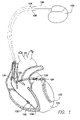
- FIG. 1 is a diagram illustrating a cardiac stimulation device in communication with a patient's heart
- FIG. 2 is a simplified, functional block diagram depicting various components of an exemplary cardiac stimulation device according to one embodiment as disclosed herein;
- FIG. 3 is a flow chart depicting an illustrative method for detecting far field R-waves
- FIG. 4 is a flow chart depicting another illustrative method for detecting far-field R-waves.
- FIG. 5 is a histogram generated by the device of FIG. 1 in accordance with one illustrative embodiment.
- FIG. 1 is a simplified diagram illustrating an implantable cardiac stimulation device 100 (as may be utilized in connection with one or more embodiments disclosed herein) in communication with a patient's heart 102 .
- the implantable cardiac stimulation device 100 is electrically connected to the patient's heart 102 by way of three leads 104 , 106 , and 108 , suitable for multi-chamber sensing and delivery of stimulating pulses and/or shock therapy.
- the implantable cardiac stimulation device 100 senses cardiac activity in, and delivers stimulating pulses or electrical shocks to, the atria and ventricles of the patient's heart 102 via leads 104 , 106 , and 108 .
- stimulation device 100 is preferably coupled to an implantable right atrial lead 104 having at least an atrial tip electrode 120 , which typically is implanted in the patient's right atrial appendage.
- stimulation device 100 is preferably coupled to a coronary sinus lead 106 designed for placement in the coronary sinus region via the coronary sinus by positioning a distal electrode adjacent to the left ventricle and/or additional electrode(s) adjacent to the left atrium.
- the coronary sinus region in the present context generally refers to the vasculature of the left ventricle, including any portion of the coronary sinus, great cardiac vein, left marginal vein, left posterior ventricular vein, middle cardiac vein, and/or small cardiac vein or any other cardiac vein accessible by the coronary sinus.
- a preferred coronary sinus lead 106 is configured to receive atrial and ventricular cardiac signals, and to deliver left ventricular pacing therapy using a left ventricular tip electrode 122 , left atrial pacing therapy using a left atrial ring electrode 124 , and shocking therapy using a left atrial coil electrode 126 .
- the electrical return path may be a different lead or the housing of the cardiac stimulation device 100 itself, according to the particular design employed.
- the implantable cardiac stimulation device 100 is preferably also in electrical communication with the patient's heart 102 by way of an implantable right ventricular lead 108 having, in the exemplary implementation illustrated in FIG. 1 , a right ventricular tip electrode 128 , a right ventricular ring electrode/sensor 130 , a right ventricular (RV) coil electrode 132 , and a superior vena cava (SVC) coil electrode 134 .
- an implantable right ventricular lead 108 having, in the exemplary implementation illustrated in FIG. 1 , a right ventricular tip electrode 128 , a right ventricular ring electrode/sensor 130 , a right ventricular (RV) coil electrode 132 , and a superior vena cava (SVC) coil electrode 134 .
- RV right ventricular
- SVC superior vena cava
- the right ventricular lead 108 is transvenously inserted into the heart 102 in such a manner that the right ventricular tip electrode 128 is positioned in the right ventricular apex, the RV coil electrode 132 is positioned in the right ventricle, and the SVC coil electrode 134 is positioned in the superior vena cava.
- the right ventricular lead 108 is thereby capable of receiving cardiac signals, and delivering stimulation in the form of pacing and/or shock therapy, to the right ventricle.
- FIG. 2 is a simplified, functional block diagram depicting various components of an exemplary cardiac stimulation device system 200 , as may be incorporated (in whole or part) into an implantable cardiac stimulation device such as, for example, cardiac stimulation device 100 illustrated in FIG. 1 .
- the cardiac stimulation device system 200 is capable of providing cardioversion, defibrillation, and pacing stimulation therapies in as many as all four chambers of the patient's heart for treating fast or slow arrhythmias, or other heart conditions, although in some cases a more streamlined set of functional features will be desired.
- the principles as have been and will be described herein are not only applicable to multi-chamber devices, but also to single-chamber, devices. It will be understood and appreciated by those skilled in the art that various components or features in the FIG. 2 system 200 could be duplicated, eliminated, or disabled, in various combinations, while still operating according to the principles as described herein.
- a case “electrode” connection 201 to the housing of the cardiac stimulation device.
- the housing for an implantable cardiac stimulation device is often referred to as the “can,” “case” or “case electrode,” and the case electrode connection 201 may in some cases be selected, via appropriate programming parameters, to act as the return electrode for various “unipolar” modes.
- the housing, through the case electrode connection 201 may further be used as a return electrode for shocking purposes, either alone or in combination with one or more coil electrodes (such as coil electrodes 126 , 132 and 134 illustrated in FIG. 1 ).
- the housing of the cardiac stimulation device includes a connector (not shown) providing a means for connecting the terminals 202 , 204 , 206 , 208 , 212 , 214 , 216 , and 218 to their respective electrodes or other components.
- the connector preferably includes a right atrial tip terminal (AR TIP) 202 adapted for connection to the atrial tip electrode 120 .
- AR TIP right atrial tip terminal
- the connector preferably includes a left ventricular tip terminal (V L TIP) 204 , a left atrial ring terminal (A L RING) 206 , and a left atrial shocking terminal (A L COIL) 208 , which are adapted for connection to the left ventricular ring electrode 122 , the left atrial tip electrode 124 , and the left atrial coil electrode 126 , respectively.
- V L TIP left ventricular tip terminal
- a L RING left atrial ring terminal
- a L COIL left atrial shocking terminal
- the connector further preferably includes a right ventricular tip terminal (V R TIP) 212 , a right ventricular ring terminal (V R RING) 214 , a right ventricular shocking terminal (R V COIL) 216 , and an SVC shocking terminal (SVC COIL) 218 , which are adapted for connection to the right ventricular tip electrode 128 , right ventricular ring electrode 130 , the RV coil electrode 132 , and the SVC coil electrode 134 , respectively.
- V R TIP right ventricular tip terminal
- V R RING right ventricular ring terminal
- R V COIL right ventricular shocking terminal
- SVC COIL SVC shocking terminal
- a programmable microcontroller 220 is preferably provided in the cardiac device stimulation system 200 to, among other things, control the various modes of stimulation therapy.
- microcontroller 220 typically includes a microprocessor, or equivalent control circuitry, designed specifically for controlling the delivery of stimulation therapy, and may further include volatile (e.g., RAM) and/or non-volatile (e.g., ROM) memory, logic and timing circuitry, state machine circuitry, and I/O circuitry.
- microcontroller 220 includes the ability to process or monitor input signals (data) as controlled by a program code stored in a designated block of memory.
- the specific type of microcontroller 220 is not critical to the described implementations. Rather, any suitable microcontroller 220 may be used that is capable of carrying out the functions described herein.
- the use of microprocessor-based control circuits for performing timing and data analysis functions are well known in the art.
- FIG. 2 further shows, in connection with the cardiac device stimulation system 200 , an atrial pulse generator 222 and a ventricular pulse generator 224 for generating pacing stimulation pulses to be delivered by the right atrial lead 104 , the coronary sinus lead 106 , and/or the right ventricular lead 108 , preferably via an electrode configuration switch 226 .
- the atrial and ventricular pulse generators 222 , 224 may include dedicated, independent pulse generators, multiplexed pulse generators, or shared pulse generators.
- the pulse generators 222 , 224 are controlled by the microcontroller 220 through control signals 228 and 230 , respectively, which serve the purpose of triggering or inhibiting the stimulation pulses.
- the microcontroller 220 may include, in the form of, e.g., digital circuitry, microcode or program instructions, or a combination thereof, various functional blocks which facilitate control of the various aspects of the cardiac stimulation device system 200 .
- the microcontroller 220 may include timing control circuitry 232 to control the timing of the stimulation pulses (e.g., pacing rate, atrio-ventricular (AV) delay, atrial interconduction (A—A) delay, or ventricular interconduction (V—V) delay, etc.) as well as to keep track of the timing of refractory periods, blanking intervals, noise detection windows, evoked response windows, alert intervals, marker channel timing, etc. These types of timing functions are well known in the art.
- Microcontroller 220 further may include one or more of an arrhythmia detector 234 , a morphology detector 236 , and a far field R-wave detector 240 . These components can be utilized by the cardiac stimulation device system 200 to detect and treat various cardiac conditions requiring treatment.
- the arrhythmia detector 234 , morphology detector 236 , and far field R-wave detector 240 may be implemented, e.g., in hardware as part of the microcontroller 220 , or as software/firmware instructions programmed into the device and executed on the microcontroller 220 during certain modes of operation.
- the electronic configuration switch 226 preferably comprises a plurality of internal switches (not shown) for connecting the desired terminals (e.g., terminals 202 , 204 , 206 , etc.) to the appropriate input/output circuits, thereby providing complete electrode programmability.
- the electronic configuration switch 226 in response to a control signal 242 from the microcontroller 220 , determines the polarity of the stimulation pulses (e.g., unipolar, bipolar, combipolar, etc.) by selectively opening/closing the appropriate combination of internal switches, in a manner well known in the art.
- Atrial sensing circuit 244 and ventricular sensing circuit 246 may be selectively coupled to the right atrial lead 104 , coronary sinus lead 106 , and the right ventricular lead 108 , preferably through the electronic configuration switch 226 .
- the atrial sensing circuit 244 and ventricular sensing circuit 246 may include, e.g., dedicated sense amplifiers, multiplexed amplifiers, or shared amplifiers.
- the electronic configuration switch 226 preferably determines the “sensing polarity” of the cardiac signal by selectively opening/closing the appropriate internal switches, in a manner well understood in the art. The foregoing features allow the clinician to program the sensing polarity independent of the stimulation polarity.
- Each sensing circuit 244 and 246 preferably employs one or more low power, precision amplifiers with programmable gain and/or automatic gain control, bandpass filtering, and threshold detection circuitry, as known in the art, to selectively sense the cardiac signal of interest.
- the automatic gain control assists the cardiac stimulation device system 200 with sensing the typically low amplitude signal characteristics associated with atrial or ventricular fibrillation.
- the outputs of the atrial and ventricular sensing circuits 244 and 246 are connected to the microcontroller 220 which, in turn, is able to trigger or inhibit the atrial and ventricular pulse generators 222 and 224 , respectively, in a programmable fashion in response to the absence or presence of cardiac activity in the appropriate chambers of the heart.
- the sensing circuits 244 and 246 receive control signals over signal lines 248 and 250 from the microcontroller 220 for purposes of controlling the gain or threshold of the sensing circuits 244 , 246 , any polarization charge removal circuitry (not shown), and/or the timing of any blocking circuitry (not shown) coupled to the inputs of the sensing circuits 244 , 246 , all in a manner well understood in the art.
- the cardiac stimulation device system 200 may utilize the atrial and ventricular sensing circuits 244 , 246 to sense cardiac signals, which can be analyzed to determine whether a particular cardiac rhythm is physiologic or pathologic.
- sensing refers to the noting of an electrical signal
- detection refers to the processing of sensed signals and noting the presence of an arrhythmia or other specific cardiac event or activity.
- the timing intervals between sensed events are preferably classified by the arrhythmia detector 234 of the microcontroller 220 by, e.g., comparing the intervals to predefined rate zone limits (e.g., bradycardia, normal, low rate VT, high rate VT, and fibrillation rate zones) and various other characteristics (e.g., sudden onset, stability, physiologic sensors, and morphology, etc.) in order to determine the type of remedial therapy that is needed (preferably including bradycardia pacing, anti-tachycardia pacing, or cardioversion/defibrillation shocks, all three of which are collectively referred to as “tiered therapy”, as well as mode switching).
- the algorithm described herein may be used in conjunction with the arrhythmia detector 234 to prevent improper mode switches, as is described in detail below.
- Cardiac signals may, in addition to being applied to atrial and ventricular sensing circuits 244 , 246 , also be applied to inputs of an analog-to-digital (A/D) data acquisition system 252 .
- the A/D data acquisition system 252 is preferably configured to acquire intracardiac electrogram signals, convert the raw analog data into a digital signal, and store the digital data for later processing and/or telemetric transmission to an external device 254 .
- the data acquisition system 252 may be selectively coupled to the right atrial lead 104 , the coronary sinus lead 106 , and the right ventricular lead 108 through the electronic configuration switch 226 to allow sampling of cardiac signals across any desired pair of electrodes.
- the data acquisition system 252 may be coupled to the microcontroller 220 , or other detection circuitry, for detecting an evoked response from the heart in response to an applied stimulus, thereby aiding in the detection of “capture.” Capture occurs when an electrical stimulus applied to the heart is of sufficient energy to depolarize the cardiac tissue, thereby causing the heart muscle to contract.
- the microcontroller 220 generally detects a depolarization signal during a window following a stimulation pulse, the presence of which indicates that capture has occurred.
- the microcontroller 220 enables capture detection by triggering the ventricular pulse generator 224 to generate a stimulation pulse, starting a capture detection window using the timing control circuitry 232 within the microcontroller 220 , and enabling the data acquisition system 252 via control signal 256 to sample the cardiac signal that falls in the capture detection window and, based on the amplitude, determine if capture has occurred.
- Capture detection may occur on a beat-by-beat basis or on a sampled basis.
- a capture threshold search can desirably be performed at regular intervals—e.g., once a day during at least the acute phase (e.g., the first 30 days after implantation) and less frequently thereafter.
- a capture threshold search procedure begins at a desired starting point (e.g., a high energy level, or else the level at which capture is currently occurring) and decreases the energy level until capture is lost. The value at which capture is lost is known as the capture threshold. Thereafter, a safety margin may be added to the capture threshold to arrive at a pacing stimulus energy value.
- the microcontroller 220 is generally coupled, via a data/address bus 262 , to a memory 260 , wherein the programmable operating parameters used by the microcontroller 220 are stored and modified, as required, in order to customize the operation of the stimulation device 100 to suit the needs of a particular patient.
- Such operating parameters may define, for example, pacing pulse amplitude, pulse duration, electrode polarity, rate, sensitivity, automatic features, arrhythmia detection criteria, and the amplitude, waveshape and vector of each shocking pulse to be delivered to the patient's heart 102 within each respective tier of therapy.
- the memory 260 is preferably large enough to store a relatively large amount of data (e.g., from the data acquisition system 252 ), which may be read out at a later time (by telemetry) and used for subsequent analysis to guide the programming of the device.
- the operating parameters of the implantable device 100 may be non-invasively programmed into the memory 260 through a telemetry circuit 264 in telemetric communication via communication link 266 with an external device 254 , such as a programmer, transtelephonic transceiver, or a diagnostic system analyzer.
- the microcontroller 220 activates the telemetry circuit 264 with a control signal 268 .
- the telemetry circuit 264 may allow intracardiac electrograms (ECGs) and status information relating to the operation of the device 100 (as contained in the microcontroller 220 or memory 260 ) to be sent to the external device 254 through an established communication link 266 .
- ECGs intracardiac electrograms
- the cardiac stimulation device system 200 can further include one or more physiologic sensors 270 , such as a “rate-responsive” sensor which is used to adjust pacing stimulation rate according to the activity level of the patient.
- the physiological sensor 270 may alternatively, or in addition, be used to detect changes in cardiac output, changes in the physiological condition of the heart, or diurnal changes in activity (e.g., detecting sleep and wake states).
- the microcontroller 220 may be programmed to respond to information received from the physiologic sensor 270 by, e.g., adjusting the various pacing parameters (such as rate, AV Delay, V—V Delay, etc.) at which the atrial and ventricular pulse generators 222 , 224 , generate stimulation pulses, or by making other dynamic adjustments.
- the physiologic sensor 270 may instead be external to the stimulation device, yet still be implanted within or carried by the patient.
- Examples of physiologic sensors that may be implemented in cardiac stimulation device system 200 include sensors that, for example, sense respiration rate and/or minute ventilation, pH of blood, ventricular gradient, and so forth.
- the physiological sensor 270 may also be embodied, for example, with reference to FIG. 1 , as a pressure sensor that is coupled to detect RV pressure that is sensed by a sensor located at ring 130 , which can perform dual functions of a ring electrode and a pressure sensor.
- the one or more physiological sensors 270 may further include one or more sensors for detecting position or postural changes. Any sensor capable of sensing such changes, either directly or indirectly, may be used for such a purpose.
- the one or more physiological sensors 270 may include an activity or position sensor (not shown) mounted within the housing of the stimulation device to detect movement in the patient's position.
- the activity or position sensor may be implemented in many ways, including as a 3D accelerometer, a sensor that detects the earth's magnetic or gravitational fields, a MEMs (micro-electro mechanical) device, and the like. Another sensor that may be used is of the type that detects activity variance.
- the cardiac stimulation device system 200 additionally includes a battery 276 for providing operating power to the circuitry shown in FIG. 2 .
- the battery 276 is preferably capable of operating at low current drains (preferably less than, e.g., 10 ⁇ A) for long periods of time, and of providing high-current pulses (for capacitor charging) when the patient requires a shock pulse.
- the battery 276 also desirably has a predictable discharge characteristic so that elective replacement time can be detected.
- the battery 276 may be of the lithium/silver vanadium oxide variety.
- the cardiac stimulation device system 200 can further include magnet detection circuitry (not shown), coupled to the microcontroller 220 , to detect when a magnet is placed in near proximity to the cardiac stimulation device.
- a magnet may be used, for example, by a clinician to perform various test functions of the cardiac stimulation device and/or to signal the microcontroller 220 that the external programmer 254 is in place to exchange data with the microcontroller 220 through the telemetry circuits 264 .
- the cardiac stimulation device system 200 further may include an impedance measuring circuit 278 , enabled by the microcontroller 220 via a control signal 280 .
- an impedance measuring circuit 278 examples include, among other things, (1) lead impedance surveillance during the acute and chronic phases for proper lead positioning or dislodgment; (2) electrode operability verification (and automatic switching to an operable pair if dislodgment occurs); (3) measurement of respiration or minute ventilation; (4) measurement of thoracic impedance for determining shock thresholds; (5) detection of whether the device has been implanted; (6) measurement of stroke volume; and (7) detection of the opening of heart valves.
- the impedance measuring circuit 278 is advantageously coupled to the electronic configuration switch 226 so that any desired electrode may be used in connection with the impedance measuring circuit 278 .
- Microcontroller 220 also controls a shocking circuit 282 through a control signal 284 (or set of control signals).
- the shocking circuit 282 may be programmed to generate shock pulses of different selectable energy magnitudes—for example, of low (up to 0.5 joules), moderate (0.5–10 joules), or high energy (11 to 40 joules)—as controlled by the microcontroller 220 .
- shock pulses are ordinarily applied to the patient's heart through at least two shocking electrodes, which, referring now to FIG. 1 , may be selected from the left atrial coil electrode 126 , the RV coil electrode 132 , and/or the SVC coil electrode 134 .
- the housing of the cardiac stimulation device may act as an active electrode in combination with the RV electrode 132 , or as part of a split electrical vector using the SVC coil electrode 134 or the left atrial coil electrode 126 (i.e., using the RV electrode as a common electrode).
- Cardioversion shocks tend to be of low to moderate energy level (so as to minimize pain felt by the patient), and may be synchronized with an R-wave. Cardioversion therapy tends to be utilized, generally, for the treatment of tachycardia. Defibrillation shocks are generally of moderate to high energy level (e.g., in the range of 5–40 joules), delivered synchronously or asynchronously (since R-waves may be too disorganized during a fibrillation episode). Defibrillation shocks are generally utilized for treating fibrillation.
- the microcontroller 220 is preferably capable of controlling the synchronous or asynchronous delivery of the shock pulses, and the provision of synchronous or asynchronous shocks may be either programmable (and may further be tailored to the particular mode or degree of therapy) or may be set by default in whole or part.
- cardiac stimulation device 100 is configured to monitor ventricular-to-atrial intervals (V-A intervals) for a plurality of pairs of events (where each pair consists of a ventricular event and the subsequent atrial event). The intervals are processed to determine if those intervals are substantially constant or stable. If they are, then it is determined that the atrial “events” are in fact far field R-waves.
- V-A intervals ventricular-to-atrial intervals
- a first step 302 the far-field R-wave discrimination process is started.
- step 302 a plurality of ventricular events and subsequent atrial events are detected.
- each pair of events i.e., a ventricular event and the subsequent atrial event
- an interval value is calculated.
- interval values for the last four pairs of events are calculated, although it will be apparent to those skilled in the art that more or less than four pairs of events may be used.
- the interval values are all recently obtained values, for example, those obtained within the last ten seconds.
- each interval value calculated at step 304 is processed to provide diagnostic information to a physician, as is described in more detail below.
- only those pairs of events (ventricular event followed by an atrial event) that are followed by another atrial event prior to a detected ventricular event are used by the algorithm.
- Those pairs of events that satisfy that requirement are likely to result from either far-field R-wave sensing or an atrial tachyarrhythmia, whereas those pairs of events that do not satisfy that requirement are likely to result from actual atrial events.
- Atrial tachyarrhythmias will have very unstable interval values and therefore are easily distinguished from far-field R-wave sensing.
- those interval values are processed to determine if the interval values are substantially constant. It will be apparent that many different methods may be utilized to determine if the interval values are substantially constant. Examples of such methods are described below.
- the algorithm determines whether the interval values are substantially constant. If not, then operation returns to step 302 , and the atrial events are not considered to be far-field R-waves. In that event, the device's arrhythmia detector 234 may determine that an atrial arrhythmia exists, which will cause device 100 to take appropriate measures, such as switching modes and the like.
- step 310 the sensed atrial events are determined to be far-field R-waves rather than actual atrial depolarizations.
- the algorithm then takes appropriate action, which can take many different forms.
- the atrial blanking period may be extended so that the far-field R-waves are no longer sensed by the atrial sensing channel.
- the device may prevent an automatic mode switch from taking place, since it has been determined that the premature atrial events are not actual atrial depolarizations.
- a record of the result can be made, such as by setting a flag or storing the record in memory, for subsequent transmission during interrogation by an external programmer.
- the device may prevent a defibrillation shock from being applied to the atrium.
- the atrial events must occur within a specified detection window in order to be used by the far-field R-wave detection algorithm. Atrial events falling outside the detection window are ignored for purposes of the algorithm.
- the detection window is defined as the period from the end of the PVAB (post-ventricular atrial blanking period) to the end of the PVARP (post-ventricular atrial refractory period). In other embodiments, other detection windows may be used. For example, a patient-specific detection window may be defined, or any other suitable detection window as will be readily understood by those skilled in the art.
- the algorithm in addition to determining whether the interval values are substantially constant, the algorithm also determines whether the interval values are relatively short. For example, this may be accomplished by determining whether the average interval value is below a preset threshold value, such as about 250 milliseconds.
- the algorithm processes the interval values to provide diagnostic information, which in one embodiment may be in the form of a histogram ( FIG. 5 ). As is shown in FIG. 5 , the majority of the interval values are due to sinus rhythm (actual atrial depolarizations) and would be relatively long values (e.g., greater than 400 milliseconds). If the device experiences far-field sensing, then the histogram displays an additional cluster of interval values that would have a very small range of values, for example on the order of about 200 millseconds.
- the stability of the interval values determines whether far-field R-wave sensing is occurring.
- only those interval values below a preset value e.g., 400 milliseconds are used to construct the histogram. Again, the stability of the interval values would indicate whether far-field R-wave sensing is occurring, as opposed to an arrhythmia, premature atrial contractions, and the like, which would result in relatively unstable interval values.
- the diagnostic information could simply be statistical information, such as an average interval value and a standard deviation for the interval values. It will be apparent to those skilled in the art that the diagnostic information can take many different forms, such as a percentage of events, when those events happened, a counter of such events, and the like. Such information may be stored in an event record, such as the one described in U.S. Pat. No. 5,487,755 to Snell et al., which is expressly incorporated herein by reference.
- FIG. 4 there is shown a flowchart of another illustrative embodiment.
- two different groups of interval values are computed, one for paced ventricular events and the other for sensed ventricular events.
- two different PVAB values are maintained, one for use after paced ventricular events and the other for use after sensed ventricular events.
- operation commences at step 400 with an atrial event being sensed within a detection window that extends from the end of PVAB to the end of PVARP.
- operation proceeds to query block 402 , where the algorithm determines the type of ventricular event that preceded the atrial event, namely whether the preceding ventricular event was a paced event (as determined by monitoring for applied ventricular pacing pulses) or a sensed (intrinsic) event (as determined by sensing a ventricular depolarization). If the preceding ventricular event was a sensed event, then operation proceeds to step 404 , and an interval value is calculated from the occurrence of the intrinsic event (R-wave) to the occurrence of the subsequent atrial event (hereinafter referred to as an “R-P interval”).
- Operation then proceeds to block 406 , and the last four R-P interval values are processed to determine if those R-P interval values are substantially constant. If not, then operation proceeds to step 412 . If on the other hand the R-P interval values are substantially constant, then operation proceeds to step 408 , and a PVAB value for sensed ventricular events (S-PVAB) is increased by an amount. As described above, the algorithm may use more or less than four interval values. In addition, the R-P interval values are preferably obtained within the last ten seconds (or some other similar period of time).
- step 408 Operation proceeds from step 408 to step 410 , where the algorithm stops any ongoing automatic mode switch that may be taking place. Operation then proceeds to step 412 to await the next cardiac event, at which time operation returns to step 400 .
- V-pace paced ventricular event
- V-P interval an interval value is determined from the paced ventricular event
- the last four of the V-P interval values are processed to determine if those V-P interval values are substantially constant. If not, then operation proceeds to step 412 . If on the other hand the V-P interval values are substantially constant, then operation proceeds to step 424 , and a PVAB value for paced ventricular events (V-PVAB) is increased by an amount. Operation then proceeds to step 410 , as described above.
- the extended V-PVAB will be used for future paced ventricular events, while the extended S-PVAB will be used for future sensed ventricular events.
- two different PVAB values are used because the duration of ventricular events can vary depending on whether the ventricular event is an intrinsic or a paced event.
- the stability of the interval values is determined by calculating an averaged deviation for the interval values, and by then comparing the averaged deviation with a threshold value.
- the threshold value is on the order of 20 msec, although other threshold values may also be used.
- the interval values are determined to be stable (i.e., far-field R-wave sensing is occurring).
- a similar equation is used for the R-P interval values.
- Other methods may be used to determine the stability of the interval values, including determining whether all of the interval values are within some predefined value of each other, and the like.
- one or more of the above-described embodiments are always in use by device 100 to monitor for far-field R-wave sensing.
- device 100 is programmed to retrieve and execute the far-field R-wave algorithm only during periods of increased patient activity, such as during exercise, because the R-wave amplitude or duration might change during exercise, such that in some patients far-field R-waves may be detected only during exercise.
- the algorithm is only executed when the patient's atrial rate gradually increases in a manner indicative of exercise. Alternately, the algorithm may be executed when the one or more physiologic sensors 270 indicate periods of increased activity.
Abstract
Description
Averaged deviation=Σ|V-P(1:4)−mean (V-P(1:4))|/4
For example, if the four V-P interval values are 10, 14, 16, and 20 msec, then the mean V-P interval value is 15 msec, and the averaged deviation is 3 msec.
Claims (46)
Priority Applications (1)
| Application Number | Priority Date | Filing Date | Title |
|---|---|---|---|
| US10/176,554 US6934585B1 (en) | 2002-06-21 | 2002-06-21 | System and method for far-field R-wave detection |
Applications Claiming Priority (1)
| Application Number | Priority Date | Filing Date | Title |
|---|---|---|---|
| US10/176,554 US6934585B1 (en) | 2002-06-21 | 2002-06-21 | System and method for far-field R-wave detection |
Publications (1)
| Publication Number | Publication Date |
|---|---|
| US6934585B1 true US6934585B1 (en) | 2005-08-23 |
Family
ID=34837116
Family Applications (1)
| Application Number | Title | Priority Date | Filing Date |
|---|---|---|---|
| US10/176,554 Expired - Fee Related US6934585B1 (en) | 2002-06-21 | 2002-06-21 | System and method for far-field R-wave detection |
Country Status (1)
| Country | Link |
|---|---|
| US (1) | US6934585B1 (en) |
Cited By (116)
| Publication number | Priority date | Publication date | Assignee | Title |
|---|---|---|---|---|
| US20040010293A1 (en) * | 2002-07-12 | 2004-01-15 | St. Jude Medical Ab | Implantable cardiac stimulator and method for controling pacing dependent on the farfield ECG |
| US20060235476A1 (en) * | 2005-04-18 | 2006-10-19 | Gunderson Bruce D | Method and apparatus for identifying oversensing using far-field intracardiac electrograms and marker channels |
| US7398123B1 (en) | 2004-03-05 | 2008-07-08 | Pacesetter, Inc. | Methods and devices for reducing the detection of inappropriate physiologic signals to reduce misdiagnosis of normal rhythms as tachyarrhythmias |
| US7437190B1 (en) * | 2004-03-02 | 2008-10-14 | Pacesetter, Inc. | Cardiac stimulation device with adjustable blanking intervals |
| US20090099617A1 (en) * | 2007-10-16 | 2009-04-16 | Hastings David F | Implantable heart stimulator providing long term cardiac monitoring with automatic notification |
| US20090281587A1 (en) * | 2008-05-07 | 2009-11-12 | Pacesetter, Inc. | System and method for detecting hidden atrial events for use with automatic mode switching within an implantable medical device |
| US20090281588A1 (en) * | 2008-05-09 | 2009-11-12 | Pacesetter, Inc. | Determining atrial time periods in conjunction with real-time testing |
| US20100023083A1 (en) * | 2008-07-22 | 2010-01-28 | Pacesetter, Inc. | Methods and devices involving automatic atrial blanking |
| US20110022106A1 (en) * | 2009-07-22 | 2011-01-27 | Pacesetter, Inc. | Systems and methods for optimizing ventricular pacing delays during atrial fibrillation |
| US8239028B2 (en) | 2009-04-24 | 2012-08-07 | Cyberonics, Inc. | Use of cardiac parameters in methods and systems for treating a chronic medical condition |
| US8337404B2 (en) | 2010-10-01 | 2012-12-25 | Flint Hills Scientific, Llc | Detecting, quantifying, and/or classifying seizures using multimodal data |
| US8382667B2 (en) | 2010-10-01 | 2013-02-26 | Flint Hills Scientific, Llc | Detecting, quantifying, and/or classifying seizures using multimodal data |
| US8417344B2 (en) | 2008-10-24 | 2013-04-09 | Cyberonics, Inc. | Dynamic cranial nerve stimulation based on brain state determination from cardiac data |
| US8452387B2 (en) | 2010-09-16 | 2013-05-28 | Flint Hills Scientific, Llc | Detecting or validating a detection of a state change from a template of heart rate derivative shape or heart beat wave complex |
| US8562536B2 (en) | 2010-04-29 | 2013-10-22 | Flint Hills Scientific, Llc | Algorithm for detecting a seizure from cardiac data |
| US8641646B2 (en) | 2010-07-30 | 2014-02-04 | Cyberonics, Inc. | Seizure detection using coordinate data |
| US8649871B2 (en) | 2010-04-29 | 2014-02-11 | Cyberonics, Inc. | Validity test adaptive constraint modification for cardiac data used for detection of state changes |
| US8679009B2 (en) | 2010-06-15 | 2014-03-25 | Flint Hills Scientific, Llc | Systems approach to comorbidity assessment |
| US8684921B2 (en) | 2010-10-01 | 2014-04-01 | Flint Hills Scientific Llc | Detecting, assessing and managing epilepsy using a multi-variate, metric-based classification analysis |
| US8725239B2 (en) | 2011-04-25 | 2014-05-13 | Cyberonics, Inc. | Identifying seizures using heart rate decrease |
| US8831732B2 (en) | 2010-04-29 | 2014-09-09 | Cyberonics, Inc. | Method, apparatus and system for validating and quantifying cardiac beat data quality |
| US8827912B2 (en) | 2009-04-24 | 2014-09-09 | Cyberonics, Inc. | Methods and systems for detecting epileptic events using NNXX, optionally with nonlinear analysis parameters |
| US8923963B2 (en) | 2012-10-31 | 2014-12-30 | Medtronic, Inc. | Leadless pacemaker system |
| US9002467B2 (en) | 2005-05-18 | 2015-04-07 | Cardiac Pacemakers, Inc. | Modular antitachyarrhythmia therapy system |
| US9050469B1 (en) | 2003-11-26 | 2015-06-09 | Flint Hills Scientific, Llc | Method and system for logging quantitative seizure information and assessing efficacy of therapy using cardiac signals |
| US9402550B2 (en) | 2011-04-29 | 2016-08-02 | Cybertronics, Inc. | Dynamic heart rate threshold for neurological event detection |
| US20160277097A1 (en) * | 2015-03-18 | 2016-09-22 | Cardiac Pacemakers, Inc. | Communications in a medical device system with temporal optimization |
| US9492671B2 (en) | 2014-05-06 | 2016-11-15 | Medtronic, Inc. | Acoustically triggered therapy delivery |
| US9504390B2 (en) | 2011-03-04 | 2016-11-29 | Globalfoundries Inc. | Detecting, assessing and managing a risk of death in epilepsy |
| US9511233B2 (en) | 2013-11-21 | 2016-12-06 | Medtronic, Inc. | Systems and methods for leadless cardiac resynchronization therapy |
| US9526909B2 (en) | 2014-08-28 | 2016-12-27 | Cardiac Pacemakers, Inc. | Medical device with triggered blanking period |
| US9592391B2 (en) | 2014-01-10 | 2017-03-14 | Cardiac Pacemakers, Inc. | Systems and methods for detecting cardiac arrhythmias |
| US9669230B2 (en) | 2015-02-06 | 2017-06-06 | Cardiac Pacemakers, Inc. | Systems and methods for treating cardiac arrhythmias |
| US9669224B2 (en) | 2014-05-06 | 2017-06-06 | Medtronic, Inc. | Triggered pacing system |
| US9731138B1 (en) | 2016-02-17 | 2017-08-15 | Medtronic, Inc. | System and method for cardiac pacing |
| US9802055B2 (en) | 2016-04-04 | 2017-10-31 | Medtronic, Inc. | Ultrasound powered pulse delivery device |
| US9808633B2 (en) | 2012-10-31 | 2017-11-07 | Medtronic, Inc. | Leadless pacemaker system |
| US9853743B2 (en) | 2015-08-20 | 2017-12-26 | Cardiac Pacemakers, Inc. | Systems and methods for communication between medical devices |
| US9956414B2 (en) | 2015-08-27 | 2018-05-01 | Cardiac Pacemakers, Inc. | Temporal configuration of a motion sensor in an implantable medical device |
| US9968787B2 (en) | 2015-08-27 | 2018-05-15 | Cardiac Pacemakers, Inc. | Spatial configuration of a motion sensor in an implantable medical device |
| US10029107B1 (en) | 2017-01-26 | 2018-07-24 | Cardiac Pacemakers, Inc. | Leadless device with overmolded components |
| US10046167B2 (en) | 2015-02-09 | 2018-08-14 | Cardiac Pacemakers, Inc. | Implantable medical device with radiopaque ID tag |
| US10065041B2 (en) | 2015-10-08 | 2018-09-04 | Cardiac Pacemakers, Inc. | Devices and methods for adjusting pacing rates in an implantable medical device |
| US10092760B2 (en) | 2015-09-11 | 2018-10-09 | Cardiac Pacemakers, Inc. | Arrhythmia detection and confirmation |
| US10137305B2 (en) | 2015-08-28 | 2018-11-27 | Cardiac Pacemakers, Inc. | Systems and methods for behaviorally responsive signal detection and therapy delivery |
| US10159842B2 (en) | 2015-08-28 | 2018-12-25 | Cardiac Pacemakers, Inc. | System and method for detecting tamponade |
| US10183170B2 (en) | 2015-12-17 | 2019-01-22 | Cardiac Pacemakers, Inc. | Conducted communication in a medical device system |
| US10206591B2 (en) | 2011-10-14 | 2019-02-19 | Flint Hills Scientific, Llc | Seizure detection methods, apparatus, and systems using an autoregression algorithm |
| US10213610B2 (en) | 2015-03-18 | 2019-02-26 | Cardiac Pacemakers, Inc. | Communications in a medical device system with link quality assessment |
| US10220211B2 (en) | 2013-01-22 | 2019-03-05 | Livanova Usa, Inc. | Methods and systems to diagnose depression |
| US10220213B2 (en) | 2015-02-06 | 2019-03-05 | Cardiac Pacemakers, Inc. | Systems and methods for safe delivery of electrical stimulation therapy |
| US10226631B2 (en) | 2015-08-28 | 2019-03-12 | Cardiac Pacemakers, Inc. | Systems and methods for infarct detection |
| US10328272B2 (en) | 2016-05-10 | 2019-06-25 | Cardiac Pacemakers, Inc. | Retrievability for implantable medical devices |
| US10350423B2 (en) | 2016-02-04 | 2019-07-16 | Cardiac Pacemakers, Inc. | Delivery system with force sensor for leadless cardiac device |
| US10357159B2 (en) | 2015-08-20 | 2019-07-23 | Cardiac Pacemakers, Inc | Systems and methods for communication between medical devices |
| US10391319B2 (en) | 2016-08-19 | 2019-08-27 | Cardiac Pacemakers, Inc. | Trans septal implantable medical device |
| US10413733B2 (en) | 2016-10-27 | 2019-09-17 | Cardiac Pacemakers, Inc. | Implantable medical device with gyroscope |
| US10426962B2 (en) | 2016-07-07 | 2019-10-01 | Cardiac Pacemakers, Inc. | Leadless pacemaker using pressure measurements for pacing capture verification |
| US10434317B2 (en) | 2016-10-31 | 2019-10-08 | Cardiac Pacemakers, Inc. | Systems and methods for activity level pacing |
| US10434314B2 (en) | 2016-10-27 | 2019-10-08 | Cardiac Pacemakers, Inc. | Use of a separate device in managing the pace pulse energy of a cardiac pacemaker |
| US10448839B2 (en) | 2012-04-23 | 2019-10-22 | Livanova Usa, Inc. | Methods, systems and apparatuses for detecting increased risk of sudden death |
| US10463305B2 (en) | 2016-10-27 | 2019-11-05 | Cardiac Pacemakers, Inc. | Multi-device cardiac resynchronization therapy with timing enhancements |
| US10512784B2 (en) | 2016-06-27 | 2019-12-24 | Cardiac Pacemakers, Inc. | Cardiac therapy system using subcutaneously sensed P-waves for resynchronization pacing management |
| US10561330B2 (en) | 2016-10-27 | 2020-02-18 | Cardiac Pacemakers, Inc. | Implantable medical device having a sense channel with performance adjustment |
| US10583301B2 (en) | 2016-11-08 | 2020-03-10 | Cardiac Pacemakers, Inc. | Implantable medical device for atrial deployment |
| US10583303B2 (en) | 2016-01-19 | 2020-03-10 | Cardiac Pacemakers, Inc. | Devices and methods for wirelessly recharging a rechargeable battery of an implantable medical device |
| US10596383B2 (en) | 2018-04-03 | 2020-03-24 | Medtronic, Inc. | Feature based sensing for leadless pacing therapy |
| US10617874B2 (en) | 2016-10-31 | 2020-04-14 | Cardiac Pacemakers, Inc. | Systems and methods for activity level pacing |
| US10632313B2 (en) | 2016-11-09 | 2020-04-28 | Cardiac Pacemakers, Inc. | Systems, devices, and methods for setting cardiac pacing pulse parameters for a cardiac pacing device |
| US10639486B2 (en) | 2016-11-21 | 2020-05-05 | Cardiac Pacemakers, Inc. | Implantable medical device with recharge coil |
| US10668294B2 (en) | 2016-05-10 | 2020-06-02 | Cardiac Pacemakers, Inc. | Leadless cardiac pacemaker configured for over the wire delivery |
| US10688304B2 (en) | 2016-07-20 | 2020-06-23 | Cardiac Pacemakers, Inc. | Method and system for utilizing an atrial contraction timing fiducial in a leadless cardiac pacemaker system |
| US10722720B2 (en) | 2014-01-10 | 2020-07-28 | Cardiac Pacemakers, Inc. | Methods and systems for improved communication between medical devices |
| US10737102B2 (en) | 2017-01-26 | 2020-08-11 | Cardiac Pacemakers, Inc. | Leadless implantable device with detachable fixation |
| US10758737B2 (en) | 2016-09-21 | 2020-09-01 | Cardiac Pacemakers, Inc. | Using sensor data from an intracardially implanted medical device to influence operation of an extracardially implantable cardioverter |
| US10758724B2 (en) | 2016-10-27 | 2020-09-01 | Cardiac Pacemakers, Inc. | Implantable medical device delivery system with integrated sensor |
| US10765871B2 (en) | 2016-10-27 | 2020-09-08 | Cardiac Pacemakers, Inc. | Implantable medical device with pressure sensor |
| US10780278B2 (en) | 2016-08-24 | 2020-09-22 | Cardiac Pacemakers, Inc. | Integrated multi-device cardiac resynchronization therapy using P-wave to pace timing |
| US10821288B2 (en) | 2017-04-03 | 2020-11-03 | Cardiac Pacemakers, Inc. | Cardiac pacemaker with pacing pulse energy adjustment based on sensed heart rate |
| US10835753B2 (en) | 2017-01-26 | 2020-11-17 | Cardiac Pacemakers, Inc. | Intra-body device communication with redundant message transmission |
| US10870008B2 (en) | 2016-08-24 | 2020-12-22 | Cardiac Pacemakers, Inc. | Cardiac resynchronization using fusion promotion for timing management |
| US10874861B2 (en) | 2018-01-04 | 2020-12-29 | Cardiac Pacemakers, Inc. | Dual chamber pacing without beat-to-beat communication |
| US10881863B2 (en) | 2016-11-21 | 2021-01-05 | Cardiac Pacemakers, Inc. | Leadless cardiac pacemaker with multimode communication |
| US10881869B2 (en) | 2016-11-21 | 2021-01-05 | Cardiac Pacemakers, Inc. | Wireless re-charge of an implantable medical device |
| US10894163B2 (en) | 2016-11-21 | 2021-01-19 | Cardiac Pacemakers, Inc. | LCP based predictive timing for cardiac resynchronization |
| US10905872B2 (en) | 2017-04-03 | 2021-02-02 | Cardiac Pacemakers, Inc. | Implantable medical device with a movable electrode biased toward an extended position |
| US10905886B2 (en) | 2015-12-28 | 2021-02-02 | Cardiac Pacemakers, Inc. | Implantable medical device for deployment across the atrioventricular septum |
| US10905889B2 (en) | 2016-09-21 | 2021-02-02 | Cardiac Pacemakers, Inc. | Leadless stimulation device with a housing that houses internal components of the leadless stimulation device and functions as the battery case and a terminal of an internal battery |
| US10918875B2 (en) | 2017-08-18 | 2021-02-16 | Cardiac Pacemakers, Inc. | Implantable medical device with a flux concentrator and a receiving coil disposed about the flux concentrator |
| US10994145B2 (en) | 2016-09-21 | 2021-05-04 | Cardiac Pacemakers, Inc. | Implantable cardiac monitor |
| US11052258B2 (en) | 2017-12-01 | 2021-07-06 | Cardiac Pacemakers, Inc. | Methods and systems for detecting atrial contraction timing fiducials within a search window from a ventricularly implanted leadless cardiac pacemaker |
| US11058880B2 (en) | 2018-03-23 | 2021-07-13 | Medtronic, Inc. | VFA cardiac therapy for tachycardia |
| US11065459B2 (en) | 2017-08-18 | 2021-07-20 | Cardiac Pacemakers, Inc. | Implantable medical device with pressure sensor |
| US11071870B2 (en) | 2017-12-01 | 2021-07-27 | Cardiac Pacemakers, Inc. | Methods and systems for detecting atrial contraction timing fiducials and determining a cardiac interval from a ventricularly implanted leadless cardiac pacemaker |
| US11116988B2 (en) | 2016-03-31 | 2021-09-14 | Cardiac Pacemakers, Inc. | Implantable medical device with rechargeable battery |
| US11147979B2 (en) | 2016-11-21 | 2021-10-19 | Cardiac Pacemakers, Inc. | Implantable medical device with a magnetically permeable housing and an inductive coil disposed about the housing |
| US11185703B2 (en) | 2017-11-07 | 2021-11-30 | Cardiac Pacemakers, Inc. | Leadless cardiac pacemaker for bundle of his pacing |
| US11207527B2 (en) | 2016-07-06 | 2021-12-28 | Cardiac Pacemakers, Inc. | Method and system for determining an atrial contraction timing fiducial in a leadless cardiac pacemaker system |
| US11207532B2 (en) | 2017-01-04 | 2021-12-28 | Cardiac Pacemakers, Inc. | Dynamic sensing updates using postural input in a multiple device cardiac rhythm management system |
| US11213676B2 (en) | 2019-04-01 | 2022-01-04 | Medtronic, Inc. | Delivery systems for VfA cardiac therapy |
| US11235163B2 (en) | 2017-09-20 | 2022-02-01 | Cardiac Pacemakers, Inc. | Implantable medical device with multiple modes of operation |
| US11235159B2 (en) | 2018-03-23 | 2022-02-01 | Medtronic, Inc. | VFA cardiac resynchronization therapy |
| US11235161B2 (en) | 2018-09-26 | 2022-02-01 | Medtronic, Inc. | Capture in ventricle-from-atrium cardiac therapy |
| US11260216B2 (en) | 2017-12-01 | 2022-03-01 | Cardiac Pacemakers, Inc. | Methods and systems for detecting atrial contraction timing fiducials during ventricular filling from a ventricularly implanted leadless cardiac pacemaker |
| US11285326B2 (en) | 2015-03-04 | 2022-03-29 | Cardiac Pacemakers, Inc. | Systems and methods for treating cardiac arrhythmias |
| US11305127B2 (en) | 2019-08-26 | 2022-04-19 | Medtronic Inc. | VfA delivery and implant region detection |
| US11400296B2 (en) | 2018-03-23 | 2022-08-02 | Medtronic, Inc. | AV synchronous VfA cardiac therapy |
| US11529523B2 (en) | 2018-01-04 | 2022-12-20 | Cardiac Pacemakers, Inc. | Handheld bridge device for providing a communication bridge between an implanted medical device and a smartphone |
| US11679265B2 (en) | 2019-02-14 | 2023-06-20 | Medtronic, Inc. | Lead-in-lead systems and methods for cardiac therapy |
| US11697025B2 (en) | 2019-03-29 | 2023-07-11 | Medtronic, Inc. | Cardiac conduction system capture |
| US11712188B2 (en) | 2019-05-07 | 2023-08-01 | Medtronic, Inc. | Posterior left bundle branch engagement |
| US11813466B2 (en) | 2020-01-27 | 2023-11-14 | Medtronic, Inc. | Atrioventricular nodal stimulation |
| US11813464B2 (en) | 2020-07-31 | 2023-11-14 | Medtronic, Inc. | Cardiac conduction system evaluation |
| US11813463B2 (en) | 2017-12-01 | 2023-11-14 | Cardiac Pacemakers, Inc. | Leadless cardiac pacemaker with reversionary behavior |
| US11911168B2 (en) | 2020-04-03 | 2024-02-27 | Medtronic, Inc. | Cardiac conduction system therapy benefit determination |
| US11951313B2 (en) | 2018-11-17 | 2024-04-09 | Medtronic, Inc. | VFA delivery systems and methods |
Citations (5)
| Publication number | Priority date | Publication date | Assignee | Title |
|---|---|---|---|---|
| US4515161A (en) * | 1984-01-10 | 1985-05-07 | Vitafin N.V. | Dual chamber pacemaker system with V-A time measurement apparatus and method |
| US5247929A (en) * | 1992-02-04 | 1993-09-28 | Vitatron Medical, B.V. | Dual chamber pacemaker with AV extension and PMT control |
| WO1997011745A1 (en) | 1995-09-29 | 1997-04-03 | Medtronic, Inc. | Modification of pacemaker tachy response based on ffrw sensing |
| US5658320A (en) | 1995-09-29 | 1997-08-19 | Medtronic, Inc. | Atrial tachyarrhythmia detection in implantable pulse generators |
| US5814083A (en) | 1995-09-29 | 1998-09-29 | Medtronic, Inc | Pacemaker tachy determination based blocked on 2:1 sensing |
-
2002
- 2002-06-21 US US10/176,554 patent/US6934585B1/en not_active Expired - Fee Related
Patent Citations (6)
| Publication number | Priority date | Publication date | Assignee | Title |
|---|---|---|---|---|
| US4515161A (en) * | 1984-01-10 | 1985-05-07 | Vitafin N.V. | Dual chamber pacemaker system with V-A time measurement apparatus and method |
| US5247929A (en) * | 1992-02-04 | 1993-09-28 | Vitatron Medical, B.V. | Dual chamber pacemaker with AV extension and PMT control |
| WO1997011745A1 (en) | 1995-09-29 | 1997-04-03 | Medtronic, Inc. | Modification of pacemaker tachy response based on ffrw sensing |
| US5658320A (en) | 1995-09-29 | 1997-08-19 | Medtronic, Inc. | Atrial tachyarrhythmia detection in implantable pulse generators |
| US5759196A (en) | 1995-09-29 | 1998-06-02 | Medtronic, Inc. | Modification of pacemaker tachy response based on FFRW sensing |
| US5814083A (en) | 1995-09-29 | 1998-09-29 | Medtronic, Inc | Pacemaker tachy determination based blocked on 2:1 sensing |
Cited By (163)
| Publication number | Priority date | Publication date | Assignee | Title |
|---|---|---|---|---|
| US20040010293A1 (en) * | 2002-07-12 | 2004-01-15 | St. Jude Medical Ab | Implantable cardiac stimulator and method for controling pacing dependent on the farfield ECG |
| US9050469B1 (en) | 2003-11-26 | 2015-06-09 | Flint Hills Scientific, Llc | Method and system for logging quantitative seizure information and assessing efficacy of therapy using cardiac signals |
| US11185695B1 (en) | 2003-11-26 | 2021-11-30 | Flint Hills Scientific, L.L.C. | Method and system for logging quantitative seizure information and assessing efficacy of therapy using cardiac signals |
| US7437190B1 (en) * | 2004-03-02 | 2008-10-14 | Pacesetter, Inc. | Cardiac stimulation device with adjustable blanking intervals |
| US7398123B1 (en) | 2004-03-05 | 2008-07-08 | Pacesetter, Inc. | Methods and devices for reducing the detection of inappropriate physiologic signals to reduce misdiagnosis of normal rhythms as tachyarrhythmias |
| US20060235476A1 (en) * | 2005-04-18 | 2006-10-19 | Gunderson Bruce D | Method and apparatus for identifying oversensing using far-field intracardiac electrograms and marker channels |
| US8792971B2 (en) | 2005-04-18 | 2014-07-29 | Medtronic, Inc. | Method and apparatus for identifying oversensing using far-field intracardiac electrograms and marker channels |
| US7567835B2 (en) * | 2005-04-18 | 2009-07-28 | Medtronic, Inc. | Method and apparatus for identifying oversensing using far-field intracardiac electrograms and marker channels |
| US20090292331A1 (en) * | 2005-04-18 | 2009-11-26 | Medtronic, Inc. | Method and apparatus for identifying oversensing using far-field intracardiac electrograms and marker channels |
| US8386024B2 (en) | 2005-04-18 | 2013-02-26 | Medtronic, Inc. | Method and apparatus for identifying oversensing using far-field intracardiac electrograms and marker channels |
| US9242113B2 (en) | 2005-05-18 | 2016-01-26 | Cardiac Pacemarkers, Inc. | Modular antitachyarrhythmia therapy system |
| US11083898B2 (en) | 2005-05-18 | 2021-08-10 | Cardiac Pacemakers, Inc. | Modular antitachyarrhythmia therapy system |
| US9002467B2 (en) | 2005-05-18 | 2015-04-07 | Cardiac Pacemakers, Inc. | Modular antitachyarrhythmia therapy system |
| US9352164B2 (en) | 2005-05-18 | 2016-05-31 | Cardiac Pacemakers, Inc. | Modular antitachyarrhythmia therapy system |
| US9993654B2 (en) | 2005-05-18 | 2018-06-12 | Cardiac Pacemakers, Inc. | Modular antitachyarrhythmia therapy system |
| US10363428B2 (en) | 2005-05-18 | 2019-07-30 | Cardiac Pacemakers, Inc. | Modular antitachyarrhythmia therapy system |
| US8649864B2 (en) * | 2007-10-16 | 2014-02-11 | Biotronik Crm Patent Ag | Implantable heart stimulator providing long term cardiac monitoring with automatic notification |
| US20090099617A1 (en) * | 2007-10-16 | 2009-04-16 | Hastings David F | Implantable heart stimulator providing long term cardiac monitoring with automatic notification |
| US20090281587A1 (en) * | 2008-05-07 | 2009-11-12 | Pacesetter, Inc. | System and method for detecting hidden atrial events for use with automatic mode switching within an implantable medical device |
| US8233980B2 (en) | 2008-05-07 | 2012-07-31 | Pacesetter, Inc. | System and method for detecting hidden atrial events for use with automatic mode switching within an implantable medical device |
| US20090281588A1 (en) * | 2008-05-09 | 2009-11-12 | Pacesetter, Inc. | Determining atrial time periods in conjunction with real-time testing |
| US20100023083A1 (en) * | 2008-07-22 | 2010-01-28 | Pacesetter, Inc. | Methods and devices involving automatic atrial blanking |
| US8126550B2 (en) | 2008-07-22 | 2012-02-28 | Pacesetter, Inc. | Methods and devices involving automatic atrial blanking |
| US8417344B2 (en) | 2008-10-24 | 2013-04-09 | Cyberonics, Inc. | Dynamic cranial nerve stimulation based on brain state determination from cardiac data |
| US8768471B2 (en) | 2008-10-24 | 2014-07-01 | Cyberonics, Inc. | Dynamic cranial nerve stimulation based on brain state determination from cardiac data |
| US8849409B2 (en) | 2008-10-24 | 2014-09-30 | Cyberonics, Inc. | Dynamic cranial nerve stimulation based on brain state determination from cardiac data |
| US8239028B2 (en) | 2009-04-24 | 2012-08-07 | Cyberonics, Inc. | Use of cardiac parameters in methods and systems for treating a chronic medical condition |
| US8827912B2 (en) | 2009-04-24 | 2014-09-09 | Cyberonics, Inc. | Methods and systems for detecting epileptic events using NNXX, optionally with nonlinear analysis parameters |
| US8396551B2 (en) * | 2009-07-22 | 2013-03-12 | Pacesetter, Inc. | Systems and methods for optimizing ventricular pacing delays during atrial fibrillation |
| US20110022106A1 (en) * | 2009-07-22 | 2011-01-27 | Pacesetter, Inc. | Systems and methods for optimizing ventricular pacing delays during atrial fibrillation |
| US9700256B2 (en) | 2010-04-29 | 2017-07-11 | Cyberonics, Inc. | Algorithm for detecting a seizure from cardiac data |
| US9241647B2 (en) | 2010-04-29 | 2016-01-26 | Cyberonics, Inc. | Algorithm for detecting a seizure from cardiac data |
| US8831732B2 (en) | 2010-04-29 | 2014-09-09 | Cyberonics, Inc. | Method, apparatus and system for validating and quantifying cardiac beat data quality |
| US8562536B2 (en) | 2010-04-29 | 2013-10-22 | Flint Hills Scientific, Llc | Algorithm for detecting a seizure from cardiac data |
| US8649871B2 (en) | 2010-04-29 | 2014-02-11 | Cyberonics, Inc. | Validity test adaptive constraint modification for cardiac data used for detection of state changes |
| US8679009B2 (en) | 2010-06-15 | 2014-03-25 | Flint Hills Scientific, Llc | Systems approach to comorbidity assessment |
| US8641646B2 (en) | 2010-07-30 | 2014-02-04 | Cyberonics, Inc. | Seizure detection using coordinate data |
| US9220910B2 (en) | 2010-07-30 | 2015-12-29 | Cyberonics, Inc. | Seizure detection using coordinate data |
| US8452387B2 (en) | 2010-09-16 | 2013-05-28 | Flint Hills Scientific, Llc | Detecting or validating a detection of a state change from a template of heart rate derivative shape or heart beat wave complex |
| US8948855B2 (en) | 2010-09-16 | 2015-02-03 | Flint Hills Scientific, Llc | Detecting and validating a detection of a state change from a template of heart rate derivative shape or heart beat wave complex |
| US8571643B2 (en) | 2010-09-16 | 2013-10-29 | Flint Hills Scientific, Llc | Detecting or validating a detection of a state change from a template of heart rate derivative shape or heart beat wave complex |
| US9020582B2 (en) | 2010-09-16 | 2015-04-28 | Flint Hills Scientific, Llc | Detecting or validating a detection of a state change from a template of heart rate derivative shape or heart beat wave complex |
| US8852100B2 (en) | 2010-10-01 | 2014-10-07 | Flint Hills Scientific, Llc | Detecting, quantifying, and/or classifying seizures using multimodal data |
| US8337404B2 (en) | 2010-10-01 | 2012-12-25 | Flint Hills Scientific, Llc | Detecting, quantifying, and/or classifying seizures using multimodal data |
| US8382667B2 (en) | 2010-10-01 | 2013-02-26 | Flint Hills Scientific, Llc | Detecting, quantifying, and/or classifying seizures using multimodal data |
| US8945006B2 (en) | 2010-10-01 | 2015-02-03 | Flunt Hills Scientific, LLC | Detecting, assessing and managing epilepsy using a multi-variate, metric-based classification analysis |
| US8888702B2 (en) | 2010-10-01 | 2014-11-18 | Flint Hills Scientific, Llc | Detecting, quantifying, and/or classifying seizures using multimodal data |
| US8684921B2 (en) | 2010-10-01 | 2014-04-01 | Flint Hills Scientific Llc | Detecting, assessing and managing epilepsy using a multi-variate, metric-based classification analysis |
| US9504390B2 (en) | 2011-03-04 | 2016-11-29 | Globalfoundries Inc. | Detecting, assessing and managing a risk of death in epilepsy |
| US8725239B2 (en) | 2011-04-25 | 2014-05-13 | Cyberonics, Inc. | Identifying seizures using heart rate decrease |
| US9498162B2 (en) | 2011-04-25 | 2016-11-22 | Cyberonics, Inc. | Identifying seizures using heart data from two or more windows |
| US9402550B2 (en) | 2011-04-29 | 2016-08-02 | Cybertronics, Inc. | Dynamic heart rate threshold for neurological event detection |
| US10206591B2 (en) | 2011-10-14 | 2019-02-19 | Flint Hills Scientific, Llc | Seizure detection methods, apparatus, and systems using an autoregression algorithm |
| US10448839B2 (en) | 2012-04-23 | 2019-10-22 | Livanova Usa, Inc. | Methods, systems and apparatuses for detecting increased risk of sudden death |
| US11596314B2 (en) | 2012-04-23 | 2023-03-07 | Livanova Usa, Inc. | Methods, systems and apparatuses for detecting increased risk of sudden death |
| US9808633B2 (en) | 2012-10-31 | 2017-11-07 | Medtronic, Inc. | Leadless pacemaker system |
| US9375580B2 (en) | 2012-10-31 | 2016-06-28 | Medtronic, Inc. | Leadless pacemaker system |
| US8923963B2 (en) | 2012-10-31 | 2014-12-30 | Medtronic, Inc. | Leadless pacemaker system |
| US10220211B2 (en) | 2013-01-22 | 2019-03-05 | Livanova Usa, Inc. | Methods and systems to diagnose depression |
| US11103707B2 (en) | 2013-01-22 | 2021-08-31 | Livanova Usa, Inc. | Methods and systems to diagnose depression |
| US9789319B2 (en) | 2013-11-21 | 2017-10-17 | Medtronic, Inc. | Systems and methods for leadless cardiac resynchronization therapy |
| US10086206B2 (en) | 2013-11-21 | 2018-10-02 | Medtronic, Inc. | Systems and methods for leadless cardiac resynchronization therapy |
| US9511233B2 (en) | 2013-11-21 | 2016-12-06 | Medtronic, Inc. | Systems and methods for leadless cardiac resynchronization therapy |
| USRE48319E1 (en) | 2013-11-21 | 2020-11-24 | Medtronic, Inc. | Systems and methods for leadless cardiac resynchronization therapy |
| US10722720B2 (en) | 2014-01-10 | 2020-07-28 | Cardiac Pacemakers, Inc. | Methods and systems for improved communication between medical devices |
| US9592391B2 (en) | 2014-01-10 | 2017-03-14 | Cardiac Pacemakers, Inc. | Systems and methods for detecting cardiac arrhythmias |
| US9492671B2 (en) | 2014-05-06 | 2016-11-15 | Medtronic, Inc. | Acoustically triggered therapy delivery |
| US9669224B2 (en) | 2014-05-06 | 2017-06-06 | Medtronic, Inc. | Triggered pacing system |
| US9526909B2 (en) | 2014-08-28 | 2016-12-27 | Cardiac Pacemakers, Inc. | Medical device with triggered blanking period |
| US10220213B2 (en) | 2015-02-06 | 2019-03-05 | Cardiac Pacemakers, Inc. | Systems and methods for safe delivery of electrical stimulation therapy |
| US11020595B2 (en) | 2015-02-06 | 2021-06-01 | Cardiac Pacemakers, Inc. | Systems and methods for treating cardiac arrhythmias |
| US9669230B2 (en) | 2015-02-06 | 2017-06-06 | Cardiac Pacemakers, Inc. | Systems and methods for treating cardiac arrhythmias |
| US11224751B2 (en) | 2015-02-06 | 2022-01-18 | Cardiac Pacemakers, Inc. | Systems and methods for safe delivery of electrical stimulation therapy |
| US10238882B2 (en) | 2015-02-06 | 2019-03-26 | Cardiac Pacemakers | Systems and methods for treating cardiac arrhythmias |
| US11020600B2 (en) | 2015-02-09 | 2021-06-01 | Cardiac Pacemakers, Inc. | Implantable medical device with radiopaque ID tag |
| US10046167B2 (en) | 2015-02-09 | 2018-08-14 | Cardiac Pacemakers, Inc. | Implantable medical device with radiopaque ID tag |
| US11285326B2 (en) | 2015-03-04 | 2022-03-29 | Cardiac Pacemakers, Inc. | Systems and methods for treating cardiac arrhythmias |
| US11476927B2 (en) | 2015-03-18 | 2022-10-18 | Cardiac Pacemakers, Inc. | Communications in a medical device system with temporal optimization |
| US10946202B2 (en) | 2015-03-18 | 2021-03-16 | Cardiac Pacemakers, Inc. | Communications in a medical device system with link quality assessment |
| US10213610B2 (en) | 2015-03-18 | 2019-02-26 | Cardiac Pacemakers, Inc. | Communications in a medical device system with link quality assessment |
| US20160277097A1 (en) * | 2015-03-18 | 2016-09-22 | Cardiac Pacemakers, Inc. | Communications in a medical device system with temporal optimization |
| US10050700B2 (en) * | 2015-03-18 | 2018-08-14 | Cardiac Pacemakers, Inc. | Communications in a medical device system with temporal optimization |
| US9853743B2 (en) | 2015-08-20 | 2017-12-26 | Cardiac Pacemakers, Inc. | Systems and methods for communication between medical devices |
| US10357159B2 (en) | 2015-08-20 | 2019-07-23 | Cardiac Pacemakers, Inc | Systems and methods for communication between medical devices |
| US10709892B2 (en) | 2015-08-27 | 2020-07-14 | Cardiac Pacemakers, Inc. | Temporal configuration of a motion sensor in an implantable medical device |
| US9968787B2 (en) | 2015-08-27 | 2018-05-15 | Cardiac Pacemakers, Inc. | Spatial configuration of a motion sensor in an implantable medical device |
| US9956414B2 (en) | 2015-08-27 | 2018-05-01 | Cardiac Pacemakers, Inc. | Temporal configuration of a motion sensor in an implantable medical device |
| US10159842B2 (en) | 2015-08-28 | 2018-12-25 | Cardiac Pacemakers, Inc. | System and method for detecting tamponade |
| US10137305B2 (en) | 2015-08-28 | 2018-11-27 | Cardiac Pacemakers, Inc. | Systems and methods for behaviorally responsive signal detection and therapy delivery |
| US10589101B2 (en) | 2015-08-28 | 2020-03-17 | Cardiac Pacemakers, Inc. | System and method for detecting tamponade |
| US10226631B2 (en) | 2015-08-28 | 2019-03-12 | Cardiac Pacemakers, Inc. | Systems and methods for infarct detection |
| US10092760B2 (en) | 2015-09-11 | 2018-10-09 | Cardiac Pacemakers, Inc. | Arrhythmia detection and confirmation |
| US10065041B2 (en) | 2015-10-08 | 2018-09-04 | Cardiac Pacemakers, Inc. | Devices and methods for adjusting pacing rates in an implantable medical device |
| US10933245B2 (en) | 2015-12-17 | 2021-03-02 | Cardiac Pacemakers, Inc. | Conducted communication in a medical device system |
| US10183170B2 (en) | 2015-12-17 | 2019-01-22 | Cardiac Pacemakers, Inc. | Conducted communication in a medical device system |
| US10905886B2 (en) | 2015-12-28 | 2021-02-02 | Cardiac Pacemakers, Inc. | Implantable medical device for deployment across the atrioventricular septum |
| US10583303B2 (en) | 2016-01-19 | 2020-03-10 | Cardiac Pacemakers, Inc. | Devices and methods for wirelessly recharging a rechargeable battery of an implantable medical device |
| US10350423B2 (en) | 2016-02-04 | 2019-07-16 | Cardiac Pacemakers, Inc. | Delivery system with force sensor for leadless cardiac device |
| US9731138B1 (en) | 2016-02-17 | 2017-08-15 | Medtronic, Inc. | System and method for cardiac pacing |
| US11116988B2 (en) | 2016-03-31 | 2021-09-14 | Cardiac Pacemakers, Inc. | Implantable medical device with rechargeable battery |
| US9802055B2 (en) | 2016-04-04 | 2017-10-31 | Medtronic, Inc. | Ultrasound powered pulse delivery device |
| US10668294B2 (en) | 2016-05-10 | 2020-06-02 | Cardiac Pacemakers, Inc. | Leadless cardiac pacemaker configured for over the wire delivery |
| US10328272B2 (en) | 2016-05-10 | 2019-06-25 | Cardiac Pacemakers, Inc. | Retrievability for implantable medical devices |
| US10512784B2 (en) | 2016-06-27 | 2019-12-24 | Cardiac Pacemakers, Inc. | Cardiac therapy system using subcutaneously sensed P-waves for resynchronization pacing management |
| US11497921B2 (en) | 2016-06-27 | 2022-11-15 | Cardiac Pacemakers, Inc. | Cardiac therapy system using subcutaneously sensed p-waves for resynchronization pacing management |
| US11207527B2 (en) | 2016-07-06 | 2021-12-28 | Cardiac Pacemakers, Inc. | Method and system for determining an atrial contraction timing fiducial in a leadless cardiac pacemaker system |
| US10426962B2 (en) | 2016-07-07 | 2019-10-01 | Cardiac Pacemakers, Inc. | Leadless pacemaker using pressure measurements for pacing capture verification |
| US10688304B2 (en) | 2016-07-20 | 2020-06-23 | Cardiac Pacemakers, Inc. | Method and system for utilizing an atrial contraction timing fiducial in a leadless cardiac pacemaker system |
| US10391319B2 (en) | 2016-08-19 | 2019-08-27 | Cardiac Pacemakers, Inc. | Trans septal implantable medical device |
| US10780278B2 (en) | 2016-08-24 | 2020-09-22 | Cardiac Pacemakers, Inc. | Integrated multi-device cardiac resynchronization therapy using P-wave to pace timing |
| US11464982B2 (en) | 2016-08-24 | 2022-10-11 | Cardiac Pacemakers, Inc. | Integrated multi-device cardiac resynchronization therapy using p-wave to pace timing |
| US10870008B2 (en) | 2016-08-24 | 2020-12-22 | Cardiac Pacemakers, Inc. | Cardiac resynchronization using fusion promotion for timing management |
| US10758737B2 (en) | 2016-09-21 | 2020-09-01 | Cardiac Pacemakers, Inc. | Using sensor data from an intracardially implanted medical device to influence operation of an extracardially implantable cardioverter |
| US10905889B2 (en) | 2016-09-21 | 2021-02-02 | Cardiac Pacemakers, Inc. | Leadless stimulation device with a housing that houses internal components of the leadless stimulation device and functions as the battery case and a terminal of an internal battery |
| US10994145B2 (en) | 2016-09-21 | 2021-05-04 | Cardiac Pacemakers, Inc. | Implantable cardiac monitor |
| US10765871B2 (en) | 2016-10-27 | 2020-09-08 | Cardiac Pacemakers, Inc. | Implantable medical device with pressure sensor |
| US10758724B2 (en) | 2016-10-27 | 2020-09-01 | Cardiac Pacemakers, Inc. | Implantable medical device delivery system with integrated sensor |
| US10561330B2 (en) | 2016-10-27 | 2020-02-18 | Cardiac Pacemakers, Inc. | Implantable medical device having a sense channel with performance adjustment |
| US10413733B2 (en) | 2016-10-27 | 2019-09-17 | Cardiac Pacemakers, Inc. | Implantable medical device with gyroscope |
| US10463305B2 (en) | 2016-10-27 | 2019-11-05 | Cardiac Pacemakers, Inc. | Multi-device cardiac resynchronization therapy with timing enhancements |
| US11305125B2 (en) | 2016-10-27 | 2022-04-19 | Cardiac Pacemakers, Inc. | Implantable medical device with gyroscope |
| US10434314B2 (en) | 2016-10-27 | 2019-10-08 | Cardiac Pacemakers, Inc. | Use of a separate device in managing the pace pulse energy of a cardiac pacemaker |
| US10617874B2 (en) | 2016-10-31 | 2020-04-14 | Cardiac Pacemakers, Inc. | Systems and methods for activity level pacing |
| US10434317B2 (en) | 2016-10-31 | 2019-10-08 | Cardiac Pacemakers, Inc. | Systems and methods for activity level pacing |
| US10583301B2 (en) | 2016-11-08 | 2020-03-10 | Cardiac Pacemakers, Inc. | Implantable medical device for atrial deployment |
| US10632313B2 (en) | 2016-11-09 | 2020-04-28 | Cardiac Pacemakers, Inc. | Systems, devices, and methods for setting cardiac pacing pulse parameters for a cardiac pacing device |
| US10881869B2 (en) | 2016-11-21 | 2021-01-05 | Cardiac Pacemakers, Inc. | Wireless re-charge of an implantable medical device |
| US10881863B2 (en) | 2016-11-21 | 2021-01-05 | Cardiac Pacemakers, Inc. | Leadless cardiac pacemaker with multimode communication |
| US10639486B2 (en) | 2016-11-21 | 2020-05-05 | Cardiac Pacemakers, Inc. | Implantable medical device with recharge coil |
| US11147979B2 (en) | 2016-11-21 | 2021-10-19 | Cardiac Pacemakers, Inc. | Implantable medical device with a magnetically permeable housing and an inductive coil disposed about the housing |
| US10894163B2 (en) | 2016-11-21 | 2021-01-19 | Cardiac Pacemakers, Inc. | LCP based predictive timing for cardiac resynchronization |
| US11207532B2 (en) | 2017-01-04 | 2021-12-28 | Cardiac Pacemakers, Inc. | Dynamic sensing updates using postural input in a multiple device cardiac rhythm management system |
| US11590353B2 (en) | 2017-01-26 | 2023-02-28 | Cardiac Pacemakers, Inc. | Intra-body device communication with redundant message transmission |
| US10737102B2 (en) | 2017-01-26 | 2020-08-11 | Cardiac Pacemakers, Inc. | Leadless implantable device with detachable fixation |
| US10835753B2 (en) | 2017-01-26 | 2020-11-17 | Cardiac Pacemakers, Inc. | Intra-body device communication with redundant message transmission |
| US10029107B1 (en) | 2017-01-26 | 2018-07-24 | Cardiac Pacemakers, Inc. | Leadless device with overmolded components |
| US10821288B2 (en) | 2017-04-03 | 2020-11-03 | Cardiac Pacemakers, Inc. | Cardiac pacemaker with pacing pulse energy adjustment based on sensed heart rate |
| US10905872B2 (en) | 2017-04-03 | 2021-02-02 | Cardiac Pacemakers, Inc. | Implantable medical device with a movable electrode biased toward an extended position |
| US11065459B2 (en) | 2017-08-18 | 2021-07-20 | Cardiac Pacemakers, Inc. | Implantable medical device with pressure sensor |
| US10918875B2 (en) | 2017-08-18 | 2021-02-16 | Cardiac Pacemakers, Inc. | Implantable medical device with a flux concentrator and a receiving coil disposed about the flux concentrator |
| US11235163B2 (en) | 2017-09-20 | 2022-02-01 | Cardiac Pacemakers, Inc. | Implantable medical device with multiple modes of operation |
| US11185703B2 (en) | 2017-11-07 | 2021-11-30 | Cardiac Pacemakers, Inc. | Leadless cardiac pacemaker for bundle of his pacing |
| US11813463B2 (en) | 2017-12-01 | 2023-11-14 | Cardiac Pacemakers, Inc. | Leadless cardiac pacemaker with reversionary behavior |
| US11071870B2 (en) | 2017-12-01 | 2021-07-27 | Cardiac Pacemakers, Inc. | Methods and systems for detecting atrial contraction timing fiducials and determining a cardiac interval from a ventricularly implanted leadless cardiac pacemaker |
| US11260216B2 (en) | 2017-12-01 | 2022-03-01 | Cardiac Pacemakers, Inc. | Methods and systems for detecting atrial contraction timing fiducials during ventricular filling from a ventricularly implanted leadless cardiac pacemaker |
| US11052258B2 (en) | 2017-12-01 | 2021-07-06 | Cardiac Pacemakers, Inc. | Methods and systems for detecting atrial contraction timing fiducials within a search window from a ventricularly implanted leadless cardiac pacemaker |
| US10874861B2 (en) | 2018-01-04 | 2020-12-29 | Cardiac Pacemakers, Inc. | Dual chamber pacing without beat-to-beat communication |
| US11529523B2 (en) | 2018-01-04 | 2022-12-20 | Cardiac Pacemakers, Inc. | Handheld bridge device for providing a communication bridge between an implanted medical device and a smartphone |
| US11235159B2 (en) | 2018-03-23 | 2022-02-01 | Medtronic, Inc. | VFA cardiac resynchronization therapy |
| US11400296B2 (en) | 2018-03-23 | 2022-08-02 | Medtronic, Inc. | AV synchronous VfA cardiac therapy |
| US11819699B2 (en) | 2018-03-23 | 2023-11-21 | Medtronic, Inc. | VfA cardiac resynchronization therapy |
| US11058880B2 (en) | 2018-03-23 | 2021-07-13 | Medtronic, Inc. | VFA cardiac therapy for tachycardia |
| US10596383B2 (en) | 2018-04-03 | 2020-03-24 | Medtronic, Inc. | Feature based sensing for leadless pacing therapy |
| US11235161B2 (en) | 2018-09-26 | 2022-02-01 | Medtronic, Inc. | Capture in ventricle-from-atrium cardiac therapy |
| US11951313B2 (en) | 2018-11-17 | 2024-04-09 | Medtronic, Inc. | VFA delivery systems and methods |
| US11679265B2 (en) | 2019-02-14 | 2023-06-20 | Medtronic, Inc. | Lead-in-lead systems and methods for cardiac therapy |
| US11697025B2 (en) | 2019-03-29 | 2023-07-11 | Medtronic, Inc. | Cardiac conduction system capture |
| US11213676B2 (en) | 2019-04-01 | 2022-01-04 | Medtronic, Inc. | Delivery systems for VfA cardiac therapy |
| US11712188B2 (en) | 2019-05-07 | 2023-08-01 | Medtronic, Inc. | Posterior left bundle branch engagement |
| US11305127B2 (en) | 2019-08-26 | 2022-04-19 | Medtronic Inc. | VfA delivery and implant region detection |
| US11813466B2 (en) | 2020-01-27 | 2023-11-14 | Medtronic, Inc. | Atrioventricular nodal stimulation |
| US11911168B2 (en) | 2020-04-03 | 2024-02-27 | Medtronic, Inc. | Cardiac conduction system therapy benefit determination |
| US11813464B2 (en) | 2020-07-31 | 2023-11-14 | Medtronic, Inc. | Cardiac conduction system evaluation |
Similar Documents
| Publication | Publication Date | Title |
|---|---|---|
| US6934585B1 (en) | System and method for far-field R-wave detection | |
| US6862477B1 (en) | Multi-site cardiac stimulation device and method for detecting retrograde conduction | |
| US6697673B1 (en) | Implantable stimulation device and method for detecting capture of a heart chamber using cross-chamber conducted depolarization | |
| US6456880B1 (en) | Implantable cardiac stimulation device for and method of monitoring progression or regression of a patient's heart condition by monitoring ventricular repolarization interval dispersion | |
| US6904321B1 (en) | System and method of identifying fusion for dual-chamber automatic capture stimulation device | |
| US6493584B1 (en) | Implantable cardiac stimulation device and method which discriminates between noise and cardiac activity | |
| US6885893B1 (en) | Implantable stimulation device and method for performing inter-chamber conduction search and conduction time measurement | |
| US6760622B2 (en) | Implantable multi-chamber cardiac stimulation device with sensing vectors | |
| US6731980B1 (en) | System and method for automatically setting a pre-ventricular atrial blanking period | |
| US8086308B2 (en) | Implantable medical device for identifying and managing intrinsic reentrant tachycardia | |
| US8639336B2 (en) | System and method for detecting and correcting atrial undersensing | |
| US6865421B2 (en) | Method and apparatus for automatic capture verification using polarity discrimination of evoked response | |
| US6587723B1 (en) | Method and system for automatically measuring capture threshold in an implantable cardiac stimulation device | |
| US6687545B1 (en) | Cardiac stimulation system and method for performing automatic capture verification during bipolar stimulation | |
| US8126550B2 (en) | Methods and devices involving automatic atrial blanking | |
| US7761160B2 (en) | System and method for determining atrioventicular pacing delay based on atrial repolarization | |
| US6711438B1 (en) | Method and apparatus for blanking T-waves from combipolar atrial cardiac signals based on expected T-wave locations | |
| US7139604B1 (en) | Cardiac stimulation system and method for discriminating sinus from non-sinus events | |
| US7174210B1 (en) | Method and apparatus for improving specificity of atrial tachycardia detection techniques in dual-unipolar or dual-bipolar implantable cardiac stimulation systems | |
| US7184834B1 (en) | Method and apparatus for improving specificity of atrial tachycardia detection techniques in dual-unipolar or dual-bipolar implantable cardiac stimulation systems | |
| US8175708B1 (en) | System and method for adjusting automatic sensitivity control parameters based on intracardiac electrogram signals | |
| US8271081B2 (en) | Systems and methods for use with an implantable medical device for discriminating VT and SVT be selectively adjusting atrial channel sensing parameters | |
| US7676265B1 (en) | Implantable cardiac stimulation device and method providing dynamic sensing configurations for bichamber stimulation and tachyarrhythmia detection | |
| US7155282B1 (en) | Automatic sensitivity control and method for use in an implantable cardiac stimulation device | |
| US8521279B2 (en) | Implantable cardiac stimulation device and method for measuring intrinsic activity metrics in multi-site pacing |
Legal Events
| Date | Code | Title | Description |
|---|---|---|---|
| AS | Assignment |
Owner name: PACESETTER, INC., CALIFORNIA Free format text: ASSIGNMENT OF ASSIGNORS INTEREST;ASSIGNORS:SCHLOSS, HAROLD C.;MAI, JUNYU;REEL/FRAME:013039/0962;SIGNING DATES FROM 20020531 TO 20020612 |
|
| REFU | Refund |
Free format text: REFUND - PAYMENT OF MAINTENANCE FEE, 4TH YEAR, LARGE ENTITY (ORIGINAL EVENT CODE: R1551); ENTITY STATUS OF PATENT OWNER: LARGE ENTITY Free format text: REFUND - SURCHARGE FOR LATE PAYMENT, LARGE ENTITY (ORIGINAL EVENT CODE: R1554); ENTITY STATUS OF PATENT OWNER: LARGE ENTITY |
|
| FPAY | Fee payment |
Year of fee payment: 4 |
|
| FPAY | Fee payment |
Year of fee payment: 8 |
|
| REMI | Maintenance fee reminder mailed | ||
| LAPS | Lapse for failure to pay maintenance fees |
Free format text: PATENT EXPIRED FOR FAILURE TO PAY MAINTENANCE FEES (ORIGINAL EVENT CODE: EXP.) |
|
| STCH | Information on status: patent discontinuation |
Free format text: PATENT EXPIRED DUE TO NONPAYMENT OF MAINTENANCE FEES UNDER 37 CFR 1.362 |
|
| FP | Lapsed due to failure to pay maintenance fee |
Effective date: 20170823 |