US6931016B1 - Virtual private network management system - Google Patents
Virtual private network management system Download PDFInfo
- Publication number
- US6931016B1 US6931016B1 US09/417,864 US41786499A US6931016B1 US 6931016 B1 US6931016 B1 US 6931016B1 US 41786499 A US41786499 A US 41786499A US 6931016 B1 US6931016 B1 US 6931016B1
- Authority
- US
- United States
- Prior art keywords
- network device
- network
- given
- message
- network devices
- Prior art date
- Legal status (The legal status is an assumption and is not a legal conclusion. Google has not performed a legal analysis and makes no representation as to the accuracy of the status listed.)
- Expired - Fee Related
Links
Images


Classifications
-
- H—ELECTRICITY
- H04—ELECTRIC COMMUNICATION TECHNIQUE
- H04L—TRANSMISSION OF DIGITAL INFORMATION, e.g. TELEGRAPHIC COMMUNICATION
- H04L41/00—Arrangements for maintenance, administration or management of data switching networks, e.g. of packet switching networks
- H04L41/28—Restricting access to network management systems or functions, e.g. using authorisation function to access network configuration
-
- H—ELECTRICITY
- H04—ELECTRIC COMMUNICATION TECHNIQUE
- H04L—TRANSMISSION OF DIGITAL INFORMATION, e.g. TELEGRAPHIC COMMUNICATION
- H04L12/00—Data switching networks
- H04L12/28—Data switching networks characterised by path configuration, e.g. LAN [Local Area Networks] or WAN [Wide Area Networks]
- H04L12/46—Interconnection of networks
- H04L12/4641—Virtual LANs, VLANs, e.g. virtual private networks [VPN]
- H04L12/4675—Dynamic sharing of VLAN information amongst network nodes
- H04L12/4679—Arrangements for the registration or de-registration of VLAN attribute values, e.g. VLAN identifiers, port VLAN membership
-
- H—ELECTRICITY
- H04—ELECTRIC COMMUNICATION TECHNIQUE
- H04L—TRANSMISSION OF DIGITAL INFORMATION, e.g. TELEGRAPHIC COMMUNICATION
- H04L63/00—Network architectures or network communication protocols for network security
- H04L63/02—Network architectures or network communication protocols for network security for separating internal from external traffic, e.g. firewalls
- H04L63/0272—Virtual private networks
-
- H—ELECTRICITY
- H04—ELECTRIC COMMUNICATION TECHNIQUE
- H04L—TRANSMISSION OF DIGITAL INFORMATION, e.g. TELEGRAPHIC COMMUNICATION
- H04L41/00—Arrangements for maintenance, administration or management of data switching networks, e.g. of packet switching networks
- H04L41/40—Arrangements for maintenance, administration or management of data switching networks, e.g. of packet switching networks using virtualisation of network functions or resources, e.g. SDN or NFV entities
Definitions
- the invention generally relates networks and, more particularly, the invention relates to managing a virtual private network.
- virtual private networks Although deployed across third party networks, virtual private networks have the look and feel of a private network, such as an intranet utilized by a private company. In fact, many currently utilized virtual private networks are deployed across the Internet to provide a private network solution at a relatively low cost.
- a virtual private network often includes two or more preconfigured network devices that each act as VPN nodes in their VPN.
- each such network device typically is preconfigured with the address of all other network devices to be in their VPN, and preselected network routes (hereinafter “tunnels”) between each of the other network devices in their VPN.
- a given VPN that utilizes the Internet may include a first router with its associated local area network, and a second router with its associated local area network. The first router is preconfigured to have the Internet Protocol address of the second router, and a set of preselected network tunnels to the second router.
- the second router is preconfigured to have the Internet Protocol address of the first router, and a set of preselected network tunnels to the first router. Accordingly, the two routers and the members of their respective local area networks communicate in their VPN across the Internet via the preselected network tunnels.
- an apparatus and method of managing a virtual private network having a set of network devices maintains a network device memory set for storing a set of network device identifiers that identifies each of the set of network devices. More particularly, a request to join the virtual private network is received from a given network device having a given network device identifier that identifies the given network device. The set of network device identifiers then is retrieved from the network device memory set to identify all network devices in the set of network devices. A notify message then is forwarded to each of the set of network devices, and a join message is forwarded to the given network device. The notify message includes the given network device identifier, while the join message includes the set of network device identifiers. The given network device identifier then is stored in the network device memory set.
- At least one of the set of network devices preferably communicates with the given network device to establish a communication tunnel with the given network device.
- the given network device in response to receipt of the join message, preferably communicates with at least one of the network devices in the set of network devices to establish a communication tunnel with the at least one of the set of network devices.
- the request may include a network identifier identifying the given virtual private network.
- the total number of network devices in the set of network devices may equal zero.
- the network device memory set may be a database that is established for the given virtual private network in response to receipt of the request.
- the apparatus and method authenticate the request to confirm the identity of the given network device.
- the request may be received from a packet based network, and the network identifier may be an Internet Protocol address.
- the join message and notify message may include data identifying the given virtual private network.
- the apparatus and method generate the notify and join messages.
- a remove message may be received from a remove network device. Once received, all network device identifiers again may be retrieved from the network device memory set, and a first message may be forwarded to all network devices identified by the retrieved network device identifiers. Each first message may include a remove identifier identifying the remove network device. In addition, in response to receipt of the first message, at least one of the network devices in the set of network devices disconnects a communication tunnel between the at least one network device and the remove network device. A second message that includes the retrieved network device identifiers may be forwarded to the remove network device.
- a method of managing a virtual private network maintains a storage device with the device identifier of each member.
- the storage device is updated as network devices are added to and removed from the virtual private network.
- a notify message and join message are generated.
- the notify message has the given network device identifier, while the join message has the device identifiers in the storage device.
- the notify message then is forwarded to each of the set of network devices, and the join message is forwarded to the given network device.
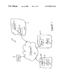
- FIG. 1 schematically shows an exemplary network arrangement in which illustrative embodiments of the invention may be implemented.
- FIG. 2 schematically shows a manager server that manages virtual private networks in accordance with illustrative embodiments of the invention.
- FIG. 3 schematically shows an illustrative database that may be in data storage for storing data relating to various VPNs.
- FIG. 4 shows an illustrative process of establishing and maintaining a VPN in accordance with illustrative embodiments of the invention.
- FIG. 5 shows an illustrative process utilized by the manager server in FIG. 2 for removing a router from a VPN.
- FIG. 1 schematically shows an exemplary network arrangement that may be utilized to implement a virtual private network (“VPN”) configured in accordance with illustrative embodiments of the invention.
- the network 10 includes a plurality of local area networks 12 that each communicate with a VPN manager server (“manager server 14 ”) via the Internet 16 .
- the manager server 14 may be a single server, or a cluster of cooperating servers. In fact, the manager server 14 need not be a part of any VPN.
- the manager server 14 may be utilized as a third party server that establishes, maintains, and terminates VPNs for any set of network devices (e.g., routers).
- Each local area network 12 includes one or more conventional routers 18 and a plurality of coupled clients 20 .
- the clients 20 each may be any type of well known network device, such as a personal computer or server.
- each router 18 includes the logic for cooperating with the other network devices (i.e., the other routers 18 and the manager server 14 ) to establish VPNs in accordance with illustrative embodiments of the invention.
- the routers 18 and manager server 14 cooperate to establish, maintain, and terminate VPNs in a manner that permits routers 18 and other network devices to join VPNs without having, in advance, special preconfigured tunnels and special preconfigured VPN membership lists. More particularly, as discussed in greater detail below, network devices joining a specified VPN are given a current list of members of the specified VPN upon joining. Accordingly, joining network devices are not required to have the identity of all such members preconfigured in their memory prior to joining. This permits membership in VPNs to be dynamically changed with relative ease. Moreover, the various tunnels utilized for transmitting data between the member network devices can be dynamically established by the existing member network devices and joining devices at the time that the joining network devices join the VPN. This enables the member network devices to establish optimal tunnels based upon current network conditions and thus, not based upon preconfigured tunnels that may be less efficient.
- the manager server 14 includes various modules for managing the membership of any VPN that may be established across the network in accord with illustrative embodiments of the invention.
- the manager server 14 may simultaneously manage any number of VPNs, such as one VPN, or hundreds of VPNs.
- the manager server 14 includes data storage 22 (e.g., a database) for storing information relating to one or more VPNs, a parser 23 for parsing data from received messages, a message generator 24 for generating messages identifying members of the various VPNs managed by the manager server 14 , and VPN logic 26 for managing the various VPNs and retrieving data from the database.
- the manager server 14 also includes an input port 28 for receiving data from the Internet 16 , and an output port 30 for forwarding data to the various routers 18 across the Internet 16 . Details of the interaction of these manager server modules are discussed below with reference to FIGS. 4 and 5 .
- FIG. 3 schematically shows a preferred VPN database (“database 22 a” ) in the data storage 22 .
- the database 22 a includes a plurality of lists of data that each relate to one VPN.
- the database 22 a shown includes data relating to a total of Z VPNs that each are managed by the manager server 14 .
- Each VPN has an associated VPN identification code, security data relating to the VPN, and a list of network devices (i.e., routes 18 ) that are members of the specified VPN.
- the security data may include authentication data for authenticating routers 18 attempting to access the VPN, such as encryption keys an/or passwords.
- FIG. 4 shows an illustrative process utilized by the manager server 14 for establishing and maintaining a VPN in accordance with illustrative embodiments of the invention.
- the process begins at step 400 in which a request message from a router 18 attempting to join a given VPN is received at the input port 28 of the manager server 14 .
- the request includes the VPN identifier identifying the VPN the router 18 is attempting to join, and the Internet Protocol address of the router 18 .
- the request also may include topology data, or authentication data (e.g., a password or an encryption key).
- the VPN logic 26 Upon receipt of the request, the VPN logic 26 parses the request to determine the VPN identifier, IP address, and the security data (step 402 ). The VPN logic 26 then determines, at step 404 , if the router 18 is permitted to join the VPN to which membership is requested. To that end, the VPN logic 26 may access the database 22 a to determine if the security data in the request matches the security data in the database 22 a. For example, a password may be compared to determine if access to the VPN is permitted. As a further example, symmetrical and asymmetrical keys may be utilized with conventional encryption methods for authentication purposes. The process ends if the router 18 is not authenticated. In such case, the message generator 24 may generate and forward a denial message to the requesting router 18 indicating that such router 18 cannot join the requested VPN.
- step 406 the VPN logic 26 determines if the VPN to which access is requested is currently executing (i.e., it is determined if such VPN exists). To that end, the VPN identifier in the request is compared to the VPN identifiers in the database 22 a. If no such VPN is found in the database 22 a, then the process continues to step 408 in which a new database 22 a for the requested VPN is initialized.
- the new database 22 a preferably is added to the existing database 22 a as another VPN entry (i.e., another list in the database 22 a ). Alternatively, the new database 22 a is separate from the existing database 22 a.
- the new database 22 a may be initialized to include the VPN identifier and Internet Protocol address (of the requesting router) parsed from the request.
- the new database 22 a also may include security data parsed from the request. Accordingly, the security data parsed from the request is utilized to authenticate subsequent network devices attempting to access the noted VPN.
- the manager server 14 cannot initiate VPNs that do not have an existing entry in the database 22 a. In such case, if there is no match, the manager server 14 may generate and forward a rejection message to the requesting router 18 . The rejection message acknowledges receipt of the join request, but indicates that the request to join the VPN was rejected.
- step 406 if it is determined that the request VPN does in fact exist and has at least one member router 18 , then the process continues to step 410 in which various messages are generated for the member routers 18 and the joining router 18 .
- the VPN logic 26 provides the message generator 24 with the Internet Protocol address of the joining router 18 , the Internet Protocol address of the member routers 18 already in the VPN, and the VPN identifier.
- the message generator 24 responsively generates a notify message for the member routers 18 , and a join message for the joining router 18 .
- the notify message includes the Internet Protocol address of the joining router 18 , the VPN identifier, and a command requesting that the router 18 receiving the message form a tunnel between it and the joining router 18 .
- the join message includes the Internet Protocol address of all member routers 18 (i.e., at least one), the VPN identifier, and a command requesting that the joining router 18 form a tunnel between it an all other member routers 18 identified in the message.
- the messages are forwarded to the output 30 and consequently, transmitted to the appropriate devices via the Internet 16 (step 412 ), thus ending the process. Accordingly, a copy of the notify message is transmitted to all routers 18 that are existing members of the VPN, while the join message is transmitted to the joining router 18 .
- a receiving router 18 parses the notify message to ascertain the VPN identifier and Internet Protocol address of the joining router 18 .
- the receiving router 18 contacts the joining router 18 via a conventional router protocol to form a communication tunnel.
- such protocols may include the Routing Information Protocol (“RIP”), the Border Gateway Protocol (“BGP”), and the Open Shortest Path First (“OSPF”).
- the joining router 18 parses the received join message to ascertain the VPN identifier and the Internet Protocol address of each router 18 in the VPN.
- the joining router 18 then also contacts the other routers 18 via a conventional router protocol to form the communication tunnel in accord with conventional processes.
- these tunnels do not necessarily include the manager server 14 and thus, are relatively direct tunnels between routers 18 .
- a tunnel includes the manager server 14 only if it is the most efficient tunnel.
- IPsec Internet Protocol security protocol
- IETF Internet Engineering Task Force
- RSA cryptography method Rivest Cipher Cryptography method
- VPNs may be formed in any desired topology.
- the initial router 18 that forms a VPN may include data relating to topology in the initial request to the manager server 14 .
- the manager server 14 consequently may store such information in the database 22 a, and include such information to subsequent notify and join messages.
- any well known topology may be used, such as full mesh topology, ring topology, star topology, or any combination thereof.
- an initial router 18 of a given VPN may designate itself as a central router 18 in a star topology.
- the database 22 a in such example includes topology data indicating that the given VPN utilizes a star topology, and that the initial router 18 is the central router 18 . Such data therefore is included in all subsequent join and notify messages.
- FIG. 5 shows an illustrative process utilized by the manager server 14 for removing a router 18 from a given VPN.
- the process begins at step 500 in which a termination message is received at the input port 28 .
- the termination message is generated and forwarded to the manager server 14 from a router 18 requesting that it be removed from the given VPN.
- the termination message includes the Internet Protocol address of the router 18 requesting to be terminated (terminated router 18 T), the VPN identifier of the given VPN, and data indicating that the terminated router 18 T is to be terminated.
- the VPN logic 26 Upon receipt of the termination message, the VPN logic 26 accesses the database 22 a to determine which routes 18 (if any) are members of the VPN at that time (step 502 ). The process continues to step 504 in which the Internet Protocol addresses of all members of the given VPN are retrieved from the database 22 a, and then added to a newly generated first termination message. In addition to the Internet Protocol addresses, the first termination message also includes the VPN identifier of the given VPN. The message generator 24 also responsively generates a second termination message that includes the Internet Protocol address of the terminated router 18 T, and the VPN identifier of the given VPN.
- first and second termination messages are forwarded to the output port 30 for transmission to the respective routers 18 (step 506 ).
- the first termination message is transmitted to the terminated router 18 T
- the second termination message is forwarded to each of the routers 18 that are members of the given VPN at that time.
- the Internet Protocol address of the terminated router 18 T is removed from the database 22 a for the given VPN.
- the terminated router 18 T Upon receipt of the first termination message, the terminated router 18 T communicates with each router 18 identified in the message to disconnect any communication tunnels established for the given VPN between it and such other router(s) 18 (step 508 ). In a similar manner, upon receipt of the second termination message, a receiving router 18 communicates with the terminated router 18 T to disconnect any communication tunnels established for the given VPN between it and the terminated router 18 T. Conventional tunnel termination methods may be utilized to terminate inter-router tunnels.
- routers 18 in a VPN can malfunction and thus, lose all communication tunnels with other routers 18 in its VPN. Moreover, a router 18 can be removed from its VPN without the interaction described above with reference to FIG. 5 and similarly stop communicating with other routers 18 in the VPN. When a router 18 is no longer communicating in one of these manners, however, the manager server 14 is not notified and thus, maintains such router's Internet Protocol address in its database 22 a. This can cause problems when subsequent routers 18 attempt to contact the router 18 that is causing the problem.
- the polling mechanism on each router 18 may transmit a status message to the manager server 14 once during each preselected time interval.
- This interval may be configured to be any time frame, such as every tenth of a second, every several hours, or any other periodic interval.
- the manager server 14 may generate and transmit an acknowledgment of receipt of the status message. Accordingly, the manager server 14 has a poll timer that is set to count down during each given time interval.
- a status message is not received from any of the routers 18 (i.e., a “non-responsive router 18 ”) in the given VPN during one given time interval, then the Internet Protocol address of the non-responsive router 18 is deleted from the database 22 a in the manager server 14 .
- the manager server 14 then generates and transmits a second message (described above with reference to FIG. 5 ) to each of the routers 18 in the VPN, causing them to terminate communication with the non-responsive router 18 .
- each router 18 instead of a polling mechanism between the manager server 14 and the routers 18 , each router 18 merely can forward a message to the manager server 14 each time such router 18 detects that one of the routers 18 in its VPN is not responsive.
- the message includes the VPN identifier and the Internet Protocol address of the non-responsive router 18 .
- the manager server 14 Upon receipt of the message, the manager server 14 then can attempt to contact the non-responsive router 18 to confirm that it, in fact, is not responding. If confirmed, then its Internet Protocol address is deleted from the database 22 a.
- the manager server 14 then generates and transmits a second message (described above) to each of the routers 18 in the VPN, causing them to terminate communication with the non-responsive router 18 .
- Illustrative embodiments of the invention may be implemented in any conventional computer programming language.
- illustrative embodiments may be implemented in a procedural programming language (e.g., “C”) or an object oriented programming language (e.g., “C++” or “JAVA”).
- Alternative embodiments of the invention may be implemented as preprogrammed hardware elements (e.g., application specific integrated circuits or digital signal processors), or other related components.
- Alternative embodiments of the invention also may be implemented as a computer program product for use with a computer system.
- Such implementation may include a series of computer instructions fixed either on a tangible medium, such as a computer readable media (e.g., a diskette, CD-ROM, ROM, or fixed disk), or transmittable to a computer system via a modem or other interface device, such as a communications adapter connected to a network over a medium.
- the medium may be either a tangible medium (e.g., optical or analog communications lines) or a medium implemented with wireless techniques (e.g., microwave, infrared or other transmission techniques).
- the series of computer instructions preferably embodies all or part of the functionality previously described herein with respect to the system.
- Such computer instructions can be written in a number of programming languages for use with many computer architectures or operating systems. Furthermore, such instructions may be stored in any memory device, such as semiconductor, magnetic, optical or other memory devices, and may be transmitted using any communications technology, such as optical, infrared, microwave, or other transmission technologies. It is expected that such a computer program product may be distributed as a removable medium with accompanying printed or electronic documentation (e.g., shrink wrapped software), preloaded with a computer system (e.g., on system ROM or fixed disk), or distributed from a server or electronic bulletin board over the network (e.g., the Internet 16 or World Wide Web).
- printed or electronic documentation e.g., shrink wrapped software
Abstract
Description
Claims (54)
Priority Applications (3)
| Application Number | Priority Date | Filing Date | Title |
|---|---|---|---|
| US09/417,864 US6931016B1 (en) | 1999-10-13 | 1999-10-13 | Virtual private network management system |
| CA002311843A CA2311843A1 (en) | 1999-10-13 | 2000-06-02 | Virtual private network management system |
| EP00308989A EP1093254A3 (en) | 1999-10-13 | 2000-10-12 | Virtual private network management system |
Applications Claiming Priority (1)
| Application Number | Priority Date | Filing Date | Title |
|---|---|---|---|
| US09/417,864 US6931016B1 (en) | 1999-10-13 | 1999-10-13 | Virtual private network management system |
Publications (1)
| Publication Number | Publication Date |
|---|---|
| US6931016B1 true US6931016B1 (en) | 2005-08-16 |
Family
ID=23655674
Family Applications (1)
| Application Number | Title | Priority Date | Filing Date |
|---|---|---|---|
| US09/417,864 Expired - Fee Related US6931016B1 (en) | 1999-10-13 | 1999-10-13 | Virtual private network management system |
Country Status (3)
| Country | Link |
|---|---|
| US (1) | US6931016B1 (en) |
| EP (1) | EP1093254A3 (en) |
| CA (1) | CA2311843A1 (en) |
Cited By (24)
| Publication number | Priority date | Publication date | Assignee | Title |
|---|---|---|---|---|
| US20040030923A1 (en) * | 2002-08-07 | 2004-02-12 | Tindal Glen D. | Method and apparatus for protecting a network from attack |
| US20040028069A1 (en) * | 2002-08-07 | 2004-02-12 | Tindal Glen D. | Event bus with passive queuing and active routing |
| US20040030771A1 (en) * | 2002-08-07 | 2004-02-12 | John Strassner | System and method for enabling directory-enabled networking |
| US20040054902A1 (en) * | 2000-12-06 | 2004-03-18 | Yoshinori Fujimoto | Virtual private network |
| US20040078457A1 (en) * | 2002-10-21 | 2004-04-22 | Tindal Glen D. | System and method for managing network-device configurations |
| US20040177246A1 (en) * | 2000-04-12 | 2004-09-09 | Rudolph Balaz | VPN enrollment protocol gateway |
| US20040230681A1 (en) * | 2002-12-06 | 2004-11-18 | John Strassner | Apparatus and method for implementing network resources to provision a service using an information model |
| US20050063357A1 (en) * | 2003-08-22 | 2005-03-24 | Eutech Cybernetics Pte Ltd | Webserver alternative for increased security |
| US20050094575A1 (en) * | 2003-10-31 | 2005-05-05 | Samsung Electronics Co., Ltd. | System for providing tunnel service capable of data communication between different types of networks |
| US20050111486A1 (en) * | 2003-11-26 | 2005-05-26 | Samsung Electronics Co., Ltd. | Device and method for controlling network devices located within private networks |
| US20060031435A1 (en) * | 2000-12-06 | 2006-02-09 | Tindal Glen D | System and method for configuring a network device |
| US20060080434A1 (en) * | 2000-12-06 | 2006-04-13 | Intelliden | Dynamic configuration of network devices to enable data transfers |
| US20060179131A1 (en) * | 2001-11-26 | 2006-08-10 | Mike Courtney | System and method for generating a representation of a configuration schema |
| US20060242690A1 (en) * | 2001-03-21 | 2006-10-26 | Wolf Jonathan S | Network configuration manager |
| US20070213972A1 (en) * | 2006-03-07 | 2007-09-13 | Sap Portals Israel Ltd. | Method and apparatus for graphically constructing applications utilizing information from multiple sources |
| US7486628B1 (en) * | 1999-12-21 | 2009-02-03 | Nortel Networks Limited | Wireless network communications |
| US20090083379A1 (en) * | 2007-09-19 | 2009-03-26 | Graham A Bent | Enabling connections for use with a network |
| US7974201B1 (en) * | 1999-10-15 | 2011-07-05 | Cisco Technology, Inc. | Technique and apparatus for using node ID as virtual private network (VPN) identifiers |
| US8219662B2 (en) | 2000-12-06 | 2012-07-10 | International Business Machines Corporation | Redirecting data generated by network devices |
| US8296400B2 (en) | 2001-08-29 | 2012-10-23 | International Business Machines Corporation | System and method for generating a configuration schema |
| US8375421B1 (en) * | 2006-03-02 | 2013-02-12 | F5 Networks, Inc. | Enabling a virtual meeting room through a firewall on a network |
| US9084291B1 (en) * | 1996-12-16 | 2015-07-14 | Ip Holdings, Inc. | Interfacing internet protocol-based wireless devices with networks |
| US9813331B2 (en) | 2013-02-05 | 2017-11-07 | International Business Machines Corporation | Assessing response routes in a network |
| US10454708B2 (en) * | 2014-03-07 | 2019-10-22 | Nec Corporation | Network system, inter-site network cooperation control apparatus, network control method, and program |
Families Citing this family (5)
| Publication number | Priority date | Publication date | Assignee | Title |
|---|---|---|---|---|
| ATE356494T1 (en) * | 2001-06-27 | 2007-03-15 | Hyglo Systems Ab | SYSTEM AND METHOD FOR PROVIDING SERVICES IN VIRTUAL PRIVATE NETWORKS |
| GB2398704B (en) | 2003-02-21 | 2005-07-06 | Toshiba Res Europ Ltd | Address autoconfiguration in ad hoc networks |
| CN1271823C (en) | 2004-01-07 | 2006-08-23 | 华为技术有限公司 | Business tunnel unpack method for wireless LAN |
| EP2134055B1 (en) * | 2008-06-10 | 2012-12-12 | secunet Security Networks Aktiengesellschaft | Method for configuring the secure transmission of data between secure networks |
| US20230006998A1 (en) * | 2021-07-02 | 2023-01-05 | Tailscale Inc. | Management of private networks over multiple local networks |
Citations (9)
| Publication number | Priority date | Publication date | Assignee | Title |
|---|---|---|---|---|
| EP0750256A2 (en) | 1995-06-23 | 1996-12-27 | Data General Corporation | Framework for managing cluster membership in a multiprocessor system |
| US5768271A (en) * | 1996-04-12 | 1998-06-16 | Alcatel Data Networks Inc. | Virtual private network |
| WO1998058356A2 (en) | 1997-06-16 | 1998-12-23 | Keilani Badieh Z Ii | System and method for processing multiple financial applications using a three-tier value network |
| US6061796A (en) * | 1997-08-26 | 2000-05-09 | V-One Corporation | Multi-access virtual private network |
| US6212548B1 (en) * | 1998-07-30 | 2001-04-03 | At & T Corp | System and method for multiple asynchronous text chat conversations |
| US6226751B1 (en) * | 1998-04-17 | 2001-05-01 | Vpnet Technologies, Inc. | Method and apparatus for configuring a virtual private network |
| US6438127B1 (en) * | 1997-03-12 | 2002-08-20 | Mannesmann Ag | Process and apparatus for the operation of virtual private networks on a common data packet communication network |
| US6442590B1 (en) * | 1999-05-27 | 2002-08-27 | Yodlee.Com, Inc. | Method and apparatus for a site-sensitive interactive chat network |
| US6484196B1 (en) * | 1998-03-20 | 2002-11-19 | Advanced Web Solutions | Internet messaging system and method for use in computer networks |
-
1999
- 1999-10-13 US US09/417,864 patent/US6931016B1/en not_active Expired - Fee Related
-
2000
- 2000-06-02 CA CA002311843A patent/CA2311843A1/en not_active Abandoned
- 2000-10-12 EP EP00308989A patent/EP1093254A3/en not_active Withdrawn
Patent Citations (9)
| Publication number | Priority date | Publication date | Assignee | Title |
|---|---|---|---|---|
| EP0750256A2 (en) | 1995-06-23 | 1996-12-27 | Data General Corporation | Framework for managing cluster membership in a multiprocessor system |
| US5768271A (en) * | 1996-04-12 | 1998-06-16 | Alcatel Data Networks Inc. | Virtual private network |
| US6438127B1 (en) * | 1997-03-12 | 2002-08-20 | Mannesmann Ag | Process and apparatus for the operation of virtual private networks on a common data packet communication network |
| WO1998058356A2 (en) | 1997-06-16 | 1998-12-23 | Keilani Badieh Z Ii | System and method for processing multiple financial applications using a three-tier value network |
| US6061796A (en) * | 1997-08-26 | 2000-05-09 | V-One Corporation | Multi-access virtual private network |
| US6484196B1 (en) * | 1998-03-20 | 2002-11-19 | Advanced Web Solutions | Internet messaging system and method for use in computer networks |
| US6226751B1 (en) * | 1998-04-17 | 2001-05-01 | Vpnet Technologies, Inc. | Method and apparatus for configuring a virtual private network |
| US6212548B1 (en) * | 1998-07-30 | 2001-04-03 | At & T Corp | System and method for multiple asynchronous text chat conversations |
| US6442590B1 (en) * | 1999-05-27 | 2002-08-27 | Yodlee.Com, Inc. | Method and apparatus for a site-sensitive interactive chat network |
Non-Patent Citations (1)
| Title |
|---|
| J. Oikarinen, Internet Relay Chat Protocol, May 1993, IETF, Network Group, Request for Comments: 1459. * |
Cited By (41)
| Publication number | Priority date | Publication date | Assignee | Title |
|---|---|---|---|---|
| US9084291B1 (en) * | 1996-12-16 | 2015-07-14 | Ip Holdings, Inc. | Interfacing internet protocol-based wireless devices with networks |
| US7974201B1 (en) * | 1999-10-15 | 2011-07-05 | Cisco Technology, Inc. | Technique and apparatus for using node ID as virtual private network (VPN) identifiers |
| US7486628B1 (en) * | 1999-12-21 | 2009-02-03 | Nortel Networks Limited | Wireless network communications |
| US20050210237A1 (en) * | 2000-04-12 | 2005-09-22 | Microsoft Corporation | VPN enrollment protocol gateway |
| US7350073B2 (en) | 2000-04-12 | 2008-03-25 | Microsoft Corporation | VPN enrollment protocol gateway |
| US7171556B2 (en) | 2000-04-12 | 2007-01-30 | Microsoft Corporation | VPN enrollment protocol gateway |
| US20040177246A1 (en) * | 2000-04-12 | 2004-09-09 | Rudolph Balaz | VPN enrollment protocol gateway |
| US20040177281A1 (en) * | 2000-04-12 | 2004-09-09 | Rudolph Balaz | VPN enrollment protocol gateway |
| US7100046B2 (en) | 2000-04-12 | 2006-08-29 | Microsoft Corporation | VPN enrollment protocol gateway |
| US20060179298A1 (en) * | 2000-04-12 | 2006-08-10 | Microsoft Corporation | VPN Enrollment Protocol Gateway |
| US7246162B2 (en) | 2000-12-06 | 2007-07-17 | Intelliden | System and method for configuring a network device |
| US7650396B2 (en) | 2000-12-06 | 2010-01-19 | Intelliden, Inc. | System and method for defining a policy enabled network |
| US20060031435A1 (en) * | 2000-12-06 | 2006-02-09 | Tindal Glen D | System and method for configuring a network device |
| US20060031434A1 (en) * | 2000-12-06 | 2006-02-09 | Tindal Glen D | System and method for configuring a network device |
| US20060080434A1 (en) * | 2000-12-06 | 2006-04-13 | Intelliden | Dynamic configuration of network devices to enable data transfers |
| US8219662B2 (en) | 2000-12-06 | 2012-07-10 | International Business Machines Corporation | Redirecting data generated by network devices |
| US7313625B2 (en) | 2000-12-06 | 2007-12-25 | Intelliden, Inc. | Dynamic configuration of network devices to enable data transfers |
| US20040054902A1 (en) * | 2000-12-06 | 2004-03-18 | Yoshinori Fujimoto | Virtual private network |
| US7246163B2 (en) | 2000-12-06 | 2007-07-17 | Intelliden | System and method for configuring a network device |
| US7472412B2 (en) | 2001-03-21 | 2008-12-30 | Wolf Jonathan S | Network configuration manager |
| US20060242690A1 (en) * | 2001-03-21 | 2006-10-26 | Wolf Jonathan S | Network configuration manager |
| US8296400B2 (en) | 2001-08-29 | 2012-10-23 | International Business Machines Corporation | System and method for generating a configuration schema |
| US20060179131A1 (en) * | 2001-11-26 | 2006-08-10 | Mike Courtney | System and method for generating a representation of a configuration schema |
| US20040030771A1 (en) * | 2002-08-07 | 2004-02-12 | John Strassner | System and method for enabling directory-enabled networking |
| US7366893B2 (en) * | 2002-08-07 | 2008-04-29 | Intelliden, Inc. | Method and apparatus for protecting a network from attack |
| US20040028069A1 (en) * | 2002-08-07 | 2004-02-12 | Tindal Glen D. | Event bus with passive queuing and active routing |
| US20040030923A1 (en) * | 2002-08-07 | 2004-02-12 | Tindal Glen D. | Method and apparatus for protecting a network from attack |
| US20040078457A1 (en) * | 2002-10-21 | 2004-04-22 | Tindal Glen D. | System and method for managing network-device configurations |
| US20040230681A1 (en) * | 2002-12-06 | 2004-11-18 | John Strassner | Apparatus and method for implementing network resources to provision a service using an information model |
| US7715326B2 (en) * | 2003-08-22 | 2010-05-11 | Eutech Cybernetics Pte. Ltd. | Webserver alternative for increased security |
| US20050063357A1 (en) * | 2003-08-22 | 2005-03-24 | Eutech Cybernetics Pte Ltd | Webserver alternative for increased security |
| US7995571B2 (en) * | 2003-10-31 | 2011-08-09 | Samsung Electronics Co., Ltd. | System for providing tunnel service capable of data communication between different types of networks |
| US20050094575A1 (en) * | 2003-10-31 | 2005-05-05 | Samsung Electronics Co., Ltd. | System for providing tunnel service capable of data communication between different types of networks |
| US20050111486A1 (en) * | 2003-11-26 | 2005-05-26 | Samsung Electronics Co., Ltd. | Device and method for controlling network devices located within private networks |
| US8375421B1 (en) * | 2006-03-02 | 2013-02-12 | F5 Networks, Inc. | Enabling a virtual meeting room through a firewall on a network |
| US20070213972A1 (en) * | 2006-03-07 | 2007-09-13 | Sap Portals Israel Ltd. | Method and apparatus for graphically constructing applications utilizing information from multiple sources |
| US8458647B2 (en) * | 2006-03-07 | 2013-06-04 | Sap Portals Israel Ltd. | Method and apparatus for graphically constructing applications utilizing information from multiple sources |
| US20090083379A1 (en) * | 2007-09-19 | 2009-03-26 | Graham A Bent | Enabling connections for use with a network |
| US8250140B2 (en) * | 2007-09-19 | 2012-08-21 | International Business Machines Corporation | Enabling connections for use with a network |
| US9813331B2 (en) | 2013-02-05 | 2017-11-07 | International Business Machines Corporation | Assessing response routes in a network |
| US10454708B2 (en) * | 2014-03-07 | 2019-10-22 | Nec Corporation | Network system, inter-site network cooperation control apparatus, network control method, and program |
Also Published As
| Publication number | Publication date |
|---|---|
| CA2311843A1 (en) | 2001-04-13 |
| EP1093254A3 (en) | 2003-01-29 |
| EP1093254A2 (en) | 2001-04-18 |
Similar Documents
| Publication | Publication Date | Title |
|---|---|---|
| US6931016B1 (en) | Virtual private network management system | |
| Bush et al. | The resource public key infrastructure (RPKI) to router protocol | |
| US11165604B2 (en) | Method and system used by terminal to connect to virtual private network, and related device | |
| FI118619B (en) | Method and system for encrypting and storing information | |
| US7827262B2 (en) | Approach for managing state information by a group of servers that services a group of clients | |
| EP1730895B1 (en) | Presence-based management in a communication network | |
| US7086086B2 (en) | System and method for maintaining N number of simultaneous cryptographic sessions using a distributed computing environment | |
| US8631228B2 (en) | Hitless manual cryptographic key refresh in secure packet networks | |
| US6484257B1 (en) | System and method for maintaining N number of simultaneous cryptographic sessions using a distributed computing environment | |
| US7421578B1 (en) | Method and apparatus for electing a leader node in a computer network | |
| US7716724B2 (en) | Extensible authentication protocol (EAP) state server | |
| US20080307110A1 (en) | Conditional BGP advertising for dynamic group VPN (DGVPN) clients | |
| US7120792B1 (en) | System and method for secure communication of routing messages | |
| US20030041170A1 (en) | System providing a virtual private network service | |
| JP2018521534A (en) | Network device and method for processing a session using a packet signature | |
| US6725276B1 (en) | Apparatus and method for authenticating messages transmitted across different multicast domains | |
| JP2004104542A (en) | Network, ipsec setting server device, ipsec processing device, and ipsec setting method used therefor | |
| US20100122084A1 (en) | Method, apparatus and system for registering new member in group key management | |
| Bush et al. | The resource public key infrastructure (RPKI) to router protocol, version 1 | |
| US20060143701A1 (en) | Techniques for authenticating network protocol control messages while changing authentication secrets | |
| US20230059348A1 (en) | Blockchain enhanced route authorization | |
| US7864770B1 (en) | Routing messages in a zero-information nested virtual private network | |
| Cisco | SNMP Support for VPNs | |
| Cisco | Kerberos Commands | |
| Cisco | Kerberos Commands |
Legal Events
| Date | Code | Title | Description |
|---|---|---|---|
| AS | Assignment |
Owner name: NORTEL NETWORKS CORPORATION, CANADA Free format text: ASSIGNMENT OF ASSIGNORS INTEREST;ASSIGNORS:ANDERSSON, LOA;WIGET, MARCEL;MADSEN, TOVE;REEL/FRAME:010433/0170;SIGNING DATES FROM 19991111 TO 19991129 |
|
| AS | Assignment |
Owner name: NORTEL NETWORKS LIMITED, CANADA Free format text: CHANGE OF NAME;ASSIGNOR:NORTEL NETWORKS CORPORATION;REEL/FRAME:011195/0706 Effective date: 20000830 Owner name: NORTEL NETWORKS LIMITED,CANADA Free format text: CHANGE OF NAME;ASSIGNOR:NORTEL NETWORKS CORPORATION;REEL/FRAME:011195/0706 Effective date: 20000830 |
|
| AS | Assignment |
Owner name: NORTEL NETWORKS LIMITED, CANADA Free format text: CHANGE OF NAME;ASSIGNOR:NORTEL NETWORKS CORPORATION;REEL/FRAME:012211/0581 Effective date: 20000501 Owner name: NORTEL NETWORKS LIMITED,CANADA Free format text: CHANGE OF NAME;ASSIGNOR:NORTEL NETWORKS CORPORATION;REEL/FRAME:012211/0581 Effective date: 20000501 |
|
| FPAY | Fee payment |
Year of fee payment: 4 |
|
| AS | Assignment |
Owner name: ROCKSTAR BIDCO, LP, NEW YORK Free format text: ASSIGNMENT OF ASSIGNORS INTEREST;ASSIGNOR:NORTEL NETWORKS LIMITED;REEL/FRAME:027164/0356 Effective date: 20110729 |
|
| FPAY | Fee payment |
Year of fee payment: 8 |
|
| AS | Assignment |
Owner name: ROCKSTAR CONSORTIUM US LP, TEXAS Free format text: ASSIGNMENT OF ASSIGNORS INTEREST;ASSIGNOR:ROCKSTAR BIDCO, LP;REEL/FRAME:032422/0919 Effective date: 20120509 |
|
| AS | Assignment |
Owner name: RPX CLEARINGHOUSE LLC, CALIFORNIA Free format text: ASSIGNMENT OF ASSIGNORS INTEREST;ASSIGNORS:ROCKSTAR CONSORTIUM US LP;ROCKSTAR CONSORTIUM LLC;BOCKSTAR TECHNOLOGIES LLC;AND OTHERS;REEL/FRAME:034924/0779 Effective date: 20150128 |
|
| AS | Assignment |
Owner name: JPMORGAN CHASE BANK, N.A., AS COLLATERAL AGENT, IL Free format text: SECURITY AGREEMENT;ASSIGNORS:RPX CORPORATION;RPX CLEARINGHOUSE LLC;REEL/FRAME:038041/0001 Effective date: 20160226 |
|
| REMI | Maintenance fee reminder mailed | ||
| LAPS | Lapse for failure to pay maintenance fees |
Free format text: PATENT EXPIRED FOR FAILURE TO PAY MAINTENANCE FEES (ORIGINAL EVENT CODE: EXP.) |
|
| STCH | Information on status: patent discontinuation |
Free format text: PATENT EXPIRED DUE TO NONPAYMENT OF MAINTENANCE FEES UNDER 37 CFR 1.362 |
|
| FP | Lapsed due to failure to pay maintenance fee |
Effective date: 20170816 |
|
| AS | Assignment |
Owner name: RPX CORPORATION, CALIFORNIA Free format text: RELEASE (REEL 038041 / FRAME 0001);ASSIGNOR:JPMORGAN CHASE BANK, N.A.;REEL/FRAME:044970/0030 Effective date: 20171222 Owner name: RPX CLEARINGHOUSE LLC, CALIFORNIA Free format text: RELEASE (REEL 038041 / FRAME 0001);ASSIGNOR:JPMORGAN CHASE BANK, N.A.;REEL/FRAME:044970/0030 Effective date: 20171222 |