US6930738B1 - Liquid crystal display with particular reflective switched states - Google Patents
Liquid crystal display with particular reflective switched states Download PDFInfo
- Publication number
- US6930738B1 US6930738B1 US09/269,503 US26950399A US6930738B1 US 6930738 B1 US6930738 B1 US 6930738B1 US 26950399 A US26950399 A US 26950399A US 6930738 B1 US6930738 B1 US 6930738B1
- Authority
- US
- United States
- Prior art keywords
- liquid crystal
- light
- polarizing film
- type polarizing
- crystal display
- Prior art date
- Legal status (The legal status is an assumption and is not a legal conclusion. Google has not performed a legal analysis and makes no representation as to the accuracy of the status listed.)
- Expired - Fee Related
Links
Images


Classifications
-
- G—PHYSICS
- G02—OPTICS
- G02F—OPTICAL DEVICES OR ARRANGEMENTS FOR THE CONTROL OF LIGHT BY MODIFICATION OF THE OPTICAL PROPERTIES OF THE MEDIA OF THE ELEMENTS INVOLVED THEREIN; NON-LINEAR OPTICS; FREQUENCY-CHANGING OF LIGHT; OPTICAL LOGIC ELEMENTS; OPTICAL ANALOGUE/DIGITAL CONVERTERS
- G02F1/00—Devices or arrangements for the control of the intensity, colour, phase, polarisation or direction of light arriving from an independent light source, e.g. switching, gating or modulating; Non-linear optics
- G02F1/01—Devices or arrangements for the control of the intensity, colour, phase, polarisation or direction of light arriving from an independent light source, e.g. switching, gating or modulating; Non-linear optics for the control of the intensity, phase, polarisation or colour
- G02F1/13—Devices or arrangements for the control of the intensity, colour, phase, polarisation or direction of light arriving from an independent light source, e.g. switching, gating or modulating; Non-linear optics for the control of the intensity, phase, polarisation or colour based on liquid crystals, e.g. single liquid crystal display cells
- G02F1/133—Constructional arrangements; Operation of liquid crystal cells; Circuit arrangements
- G02F1/1333—Constructional arrangements; Manufacturing methods
- G02F1/1335—Structural association of cells with optical devices, e.g. polarisers or reflectors
- G02F1/133528—Polarisers
- G02F1/133536—Reflective polarizers
-
- G—PHYSICS
- G02—OPTICS
- G02F—OPTICAL DEVICES OR ARRANGEMENTS FOR THE CONTROL OF LIGHT BY MODIFICATION OF THE OPTICAL PROPERTIES OF THE MEDIA OF THE ELEMENTS INVOLVED THEREIN; NON-LINEAR OPTICS; FREQUENCY-CHANGING OF LIGHT; OPTICAL LOGIC ELEMENTS; OPTICAL ANALOGUE/DIGITAL CONVERTERS
- G02F1/00—Devices or arrangements for the control of the intensity, colour, phase, polarisation or direction of light arriving from an independent light source, e.g. switching, gating or modulating; Non-linear optics
- G02F1/01—Devices or arrangements for the control of the intensity, colour, phase, polarisation or direction of light arriving from an independent light source, e.g. switching, gating or modulating; Non-linear optics for the control of the intensity, phase, polarisation or colour
- G02F1/13—Devices or arrangements for the control of the intensity, colour, phase, polarisation or direction of light arriving from an independent light source, e.g. switching, gating or modulating; Non-linear optics for the control of the intensity, phase, polarisation or colour based on liquid crystals, e.g. single liquid crystal display cells
- G02F1/133—Constructional arrangements; Operation of liquid crystal cells; Circuit arrangements
- G02F1/1333—Constructional arrangements; Manufacturing methods
- G02F1/1335—Structural association of cells with optical devices, e.g. polarisers or reflectors
-
- G—PHYSICS
- G02—OPTICS
- G02F—OPTICAL DEVICES OR ARRANGEMENTS FOR THE CONTROL OF LIGHT BY MODIFICATION OF THE OPTICAL PROPERTIES OF THE MEDIA OF THE ELEMENTS INVOLVED THEREIN; NON-LINEAR OPTICS; FREQUENCY-CHANGING OF LIGHT; OPTICAL LOGIC ELEMENTS; OPTICAL ANALOGUE/DIGITAL CONVERTERS
- G02F1/00—Devices or arrangements for the control of the intensity, colour, phase, polarisation or direction of light arriving from an independent light source, e.g. switching, gating or modulating; Non-linear optics
- G02F1/01—Devices or arrangements for the control of the intensity, colour, phase, polarisation or direction of light arriving from an independent light source, e.g. switching, gating or modulating; Non-linear optics for the control of the intensity, phase, polarisation or colour
- G02F1/13—Devices or arrangements for the control of the intensity, colour, phase, polarisation or direction of light arriving from an independent light source, e.g. switching, gating or modulating; Non-linear optics for the control of the intensity, phase, polarisation or colour based on liquid crystals, e.g. single liquid crystal display cells
- G02F1/133—Constructional arrangements; Operation of liquid crystal cells; Circuit arrangements
- G02F1/13306—Circuit arrangements or driving methods for the control of single liquid crystal cells
- G02F1/13324—Circuits comprising solar cells
-
- G—PHYSICS
- G02—OPTICS
- G02F—OPTICAL DEVICES OR ARRANGEMENTS FOR THE CONTROL OF LIGHT BY MODIFICATION OF THE OPTICAL PROPERTIES OF THE MEDIA OF THE ELEMENTS INVOLVED THEREIN; NON-LINEAR OPTICS; FREQUENCY-CHANGING OF LIGHT; OPTICAL LOGIC ELEMENTS; OPTICAL ANALOGUE/DIGITAL CONVERTERS
- G02F1/00—Devices or arrangements for the control of the intensity, colour, phase, polarisation or direction of light arriving from an independent light source, e.g. switching, gating or modulating; Non-linear optics
- G02F1/01—Devices or arrangements for the control of the intensity, colour, phase, polarisation or direction of light arriving from an independent light source, e.g. switching, gating or modulating; Non-linear optics for the control of the intensity, phase, polarisation or colour
- G02F1/13—Devices or arrangements for the control of the intensity, colour, phase, polarisation or direction of light arriving from an independent light source, e.g. switching, gating or modulating; Non-linear optics for the control of the intensity, phase, polarisation or colour based on liquid crystals, e.g. single liquid crystal display cells
- G02F1/133—Constructional arrangements; Operation of liquid crystal cells; Circuit arrangements
- G02F1/1333—Constructional arrangements; Manufacturing methods
- G02F1/1335—Structural association of cells with optical devices, e.g. polarisers or reflectors
- G02F1/133504—Diffusing, scattering, diffracting elements
-
- G—PHYSICS
- G02—OPTICS
- G02F—OPTICAL DEVICES OR ARRANGEMENTS FOR THE CONTROL OF LIGHT BY MODIFICATION OF THE OPTICAL PROPERTIES OF THE MEDIA OF THE ELEMENTS INVOLVED THEREIN; NON-LINEAR OPTICS; FREQUENCY-CHANGING OF LIGHT; OPTICAL LOGIC ELEMENTS; OPTICAL ANALOGUE/DIGITAL CONVERTERS
- G02F1/00—Devices or arrangements for the control of the intensity, colour, phase, polarisation or direction of light arriving from an independent light source, e.g. switching, gating or modulating; Non-linear optics
- G02F1/01—Devices or arrangements for the control of the intensity, colour, phase, polarisation or direction of light arriving from an independent light source, e.g. switching, gating or modulating; Non-linear optics for the control of the intensity, phase, polarisation or colour
- G02F1/13—Devices or arrangements for the control of the intensity, colour, phase, polarisation or direction of light arriving from an independent light source, e.g. switching, gating or modulating; Non-linear optics for the control of the intensity, phase, polarisation or colour based on liquid crystals, e.g. single liquid crystal display cells
- G02F1/133—Constructional arrangements; Operation of liquid crystal cells; Circuit arrangements
- G02F1/1333—Constructional arrangements; Manufacturing methods
- G02F1/1335—Structural association of cells with optical devices, e.g. polarisers or reflectors
- G02F1/133509—Filters, e.g. light shielding masks
-
- G—PHYSICS
- G02—OPTICS
- G02F—OPTICAL DEVICES OR ARRANGEMENTS FOR THE CONTROL OF LIGHT BY MODIFICATION OF THE OPTICAL PROPERTIES OF THE MEDIA OF THE ELEMENTS INVOLVED THEREIN; NON-LINEAR OPTICS; FREQUENCY-CHANGING OF LIGHT; OPTICAL LOGIC ELEMENTS; OPTICAL ANALOGUE/DIGITAL CONVERTERS
- G02F1/00—Devices or arrangements for the control of the intensity, colour, phase, polarisation or direction of light arriving from an independent light source, e.g. switching, gating or modulating; Non-linear optics
- G02F1/01—Devices or arrangements for the control of the intensity, colour, phase, polarisation or direction of light arriving from an independent light source, e.g. switching, gating or modulating; Non-linear optics for the control of the intensity, phase, polarisation or colour
- G02F1/13—Devices or arrangements for the control of the intensity, colour, phase, polarisation or direction of light arriving from an independent light source, e.g. switching, gating or modulating; Non-linear optics for the control of the intensity, phase, polarisation or colour based on liquid crystals, e.g. single liquid crystal display cells
- G02F1/133—Constructional arrangements; Operation of liquid crystal cells; Circuit arrangements
- G02F1/1333—Constructional arrangements; Manufacturing methods
- G02F1/1335—Structural association of cells with optical devices, e.g. polarisers or reflectors
- G02F1/1336—Illuminating devices
- G02F1/13362—Illuminating devices providing polarized light, e.g. by converting a polarisation component into another one
-
- G—PHYSICS
- G02—OPTICS
- G02F—OPTICAL DEVICES OR ARRANGEMENTS FOR THE CONTROL OF LIGHT BY MODIFICATION OF THE OPTICAL PROPERTIES OF THE MEDIA OF THE ELEMENTS INVOLVED THEREIN; NON-LINEAR OPTICS; FREQUENCY-CHANGING OF LIGHT; OPTICAL LOGIC ELEMENTS; OPTICAL ANALOGUE/DIGITAL CONVERTERS
- G02F1/00—Devices or arrangements for the control of the intensity, colour, phase, polarisation or direction of light arriving from an independent light source, e.g. switching, gating or modulating; Non-linear optics
- G02F1/01—Devices or arrangements for the control of the intensity, colour, phase, polarisation or direction of light arriving from an independent light source, e.g. switching, gating or modulating; Non-linear optics for the control of the intensity, phase, polarisation or colour
- G02F1/13—Devices or arrangements for the control of the intensity, colour, phase, polarisation or direction of light arriving from an independent light source, e.g. switching, gating or modulating; Non-linear optics for the control of the intensity, phase, polarisation or colour based on liquid crystals, e.g. single liquid crystal display cells
- G02F1/133—Constructional arrangements; Operation of liquid crystal cells; Circuit arrangements
- G02F1/1333—Constructional arrangements; Manufacturing methods
- G02F1/1335—Structural association of cells with optical devices, e.g. polarisers or reflectors
- G02F1/13363—Birefringent elements, e.g. for optical compensation
- G02F1/133634—Birefringent elements, e.g. for optical compensation the refractive index Nz perpendicular to the element surface being different from in-plane refractive indices Nx and Ny, e.g. biaxial or with normal optical axis
-
- G—PHYSICS
- G02—OPTICS
- G02F—OPTICAL DEVICES OR ARRANGEMENTS FOR THE CONTROL OF LIGHT BY MODIFICATION OF THE OPTICAL PROPERTIES OF THE MEDIA OF THE ELEMENTS INVOLVED THEREIN; NON-LINEAR OPTICS; FREQUENCY-CHANGING OF LIGHT; OPTICAL LOGIC ELEMENTS; OPTICAL ANALOGUE/DIGITAL CONVERTERS
- G02F1/00—Devices or arrangements for the control of the intensity, colour, phase, polarisation or direction of light arriving from an independent light source, e.g. switching, gating or modulating; Non-linear optics
- G02F1/01—Devices or arrangements for the control of the intensity, colour, phase, polarisation or direction of light arriving from an independent light source, e.g. switching, gating or modulating; Non-linear optics for the control of the intensity, phase, polarisation or colour
- G02F1/13—Devices or arrangements for the control of the intensity, colour, phase, polarisation or direction of light arriving from an independent light source, e.g. switching, gating or modulating; Non-linear optics for the control of the intensity, phase, polarisation or colour based on liquid crystals, e.g. single liquid crystal display cells
- G02F1/137—Devices or arrangements for the control of the intensity, colour, phase, polarisation or direction of light arriving from an independent light source, e.g. switching, gating or modulating; Non-linear optics for the control of the intensity, phase, polarisation or colour based on liquid crystals, e.g. single liquid crystal display cells characterised by the electro-optical or magneto-optical effect, e.g. field-induced phase transition, orientation effect, guest-host interaction or dynamic scattering
- G02F1/139—Devices or arrangements for the control of the intensity, colour, phase, polarisation or direction of light arriving from an independent light source, e.g. switching, gating or modulating; Non-linear optics for the control of the intensity, phase, polarisation or colour based on liquid crystals, e.g. single liquid crystal display cells characterised by the electro-optical or magneto-optical effect, e.g. field-induced phase transition, orientation effect, guest-host interaction or dynamic scattering based on orientation effects in which the liquid crystal remains transparent
- G02F1/1396—Devices or arrangements for the control of the intensity, colour, phase, polarisation or direction of light arriving from an independent light source, e.g. switching, gating or modulating; Non-linear optics for the control of the intensity, phase, polarisation or colour based on liquid crystals, e.g. single liquid crystal display cells characterised by the electro-optical or magneto-optical effect, e.g. field-induced phase transition, orientation effect, guest-host interaction or dynamic scattering based on orientation effects in which the liquid crystal remains transparent the liquid crystal being selectively controlled between a twisted state and a non-twisted state, e.g. TN-LC cell
- G02F1/1397—Devices or arrangements for the control of the intensity, colour, phase, polarisation or direction of light arriving from an independent light source, e.g. switching, gating or modulating; Non-linear optics for the control of the intensity, phase, polarisation or colour based on liquid crystals, e.g. single liquid crystal display cells characterised by the electro-optical or magneto-optical effect, e.g. field-induced phase transition, orientation effect, guest-host interaction or dynamic scattering based on orientation effects in which the liquid crystal remains transparent the liquid crystal being selectively controlled between a twisted state and a non-twisted state, e.g. TN-LC cell the twist being substantially higher than 90°, e.g. STN-, SBE-, OMI-LC cells
-
- G—PHYSICS
- G02—OPTICS
- G02F—OPTICAL DEVICES OR ARRANGEMENTS FOR THE CONTROL OF LIGHT BY MODIFICATION OF THE OPTICAL PROPERTIES OF THE MEDIA OF THE ELEMENTS INVOLVED THEREIN; NON-LINEAR OPTICS; FREQUENCY-CHANGING OF LIGHT; OPTICAL LOGIC ELEMENTS; OPTICAL ANALOGUE/DIGITAL CONVERTERS
- G02F2201/00—Constructional arrangements not provided for in groups G02F1/00 - G02F7/00
- G02F2201/08—Constructional arrangements not provided for in groups G02F1/00 - G02F7/00 light absorbing layer
-
- G—PHYSICS
- G02—OPTICS
- G02F—OPTICAL DEVICES OR ARRANGEMENTS FOR THE CONTROL OF LIGHT BY MODIFICATION OF THE OPTICAL PROPERTIES OF THE MEDIA OF THE ELEMENTS INVOLVED THEREIN; NON-LINEAR OPTICS; FREQUENCY-CHANGING OF LIGHT; OPTICAL LOGIC ELEMENTS; OPTICAL ANALOGUE/DIGITAL CONVERTERS
- G02F2413/00—Indexing scheme related to G02F1/13363, i.e. to birefringent elements, e.g. for optical compensation, characterised by the number, position, orientation or value of the compensation plates
- G02F2413/15—Indexing scheme related to G02F1/13363, i.e. to birefringent elements, e.g. for optical compensation, characterised by the number, position, orientation or value of the compensation plates with twisted orientation, e.g. comprising helically oriented LC-molecules or a plurality of twisted birefringent sublayers
Definitions
- a retardation film is provided outside the second substrate of the STN liquid crystal cell and an absorption-type polarizing film which absorbs the light linearly polarized in the direction orthogonal to the transmission axis thereof is provided outside the retardation film. Furthermore, a reflection-type polarizing film which reflects the light linearly polarized in the direction orthogonal to the transmission axis thereof is provided outside the first substrate of the STN liquid crystal cell described above and a light absorbing member is provided outside the reflection-type polarizing film.
- an alignment film (not shown).
- the reflection-type polarizing film 10 is a polarizing film or sheet which transmits the light linearly polarized in the direction parallel to the transmission axis thereof and reflects the light linearly polarized in the direction orthogonal to the transmission axis thereof.
- the reflection-type polarizing film 10 which is made by thin films being formed on a transparent base film in multi-layered structure, for instance, Optical Film D-BEF (trade name) sold by Sumitomo 3M Co. Ltd. is used.
- D-BEF is a product to be used typically for raising the luminance of a back light and serves sufficiently as the reflection-type polarizing film in the embodiment.
- the retardation film 13 serves as a birefringence layer and a biaxial stretching film or a uniaxial stretching film can be used for the purpose.
- the absorption-type polarizing film 8 is structured in such a manner that a transmission axis 8 a shown in FIG. 3 is disposed at an angle of ⁇ 70° with respect to the horizontal axis 30 (0°) and the retardation film 13 with the retardation value of 590 nm is disposed between the STN liquid crystal cell 16 and the absorption-type polarizing film 8 , with a phase delay axis 13 a thereof being at an angle of 50° with respect to the horizontal axis 30 .
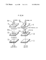
- FIG. 4 shows an “off-state” in which voltage is not applied across the first and second electrodes 3 and 4 of the STN liquid crystal cell 16 , and the left shows an “on-state” in which voltage is applied respectively.
- the elliptically polarized light is compensated during passage through the STN liquid crystal cell 16 to be a substantially linearly polarized light, and is rotated about 55° with respect to the transmission axis 8 a of the absorption-type polarizing film 8 to emit from the position at ⁇ 15° with respect to the horizontal axis 30 in FIG. 3 .
- the linearly polarized light incident onto the reflection-type polarizing film 10 of which the direction of the polarization becomes parallel to the transmission axis 10 a of the reflection-type polarizing film 10 , thus all passes through the reflection-type polarizing film 10 and is absorbed in the light absorbing film 11 .
- a sheet of red paper is used as the light absorbing film 11 , therefore red light is reflected and passes back to emit to the visible side. Thus a red display can be obtained.
- this liquid crystal display device information with letters and figures can be displayed in color on a metallic silver background, and enough contrast and an excellent viewing angle characteristic can be obtained.
- the STN liquid crystal cell is used as a liquid crystal cell, thereby the nematic liquid crystal molecules sharply change in accordance with the applied voltage and so the shapeness in the optical characteristic can be improved.
- the number of scanning lines can be increased up to 100 to 400 lines even in a scanning by simple-matrix driving, accordingly, a large-scale liquid crystal display device and a high-density liquid crystal display device can be provided.
- the viewing angle characteristic is also improved.
- the use of red paper as the light absorbing film 11 results in the liquid crystal display device to perform a red display on a metallic silver background.
- the color tone of the liquid crystal cell in the on-state can be optionally changed by changing the material of the light absorbing film 11 .
- the use of a black film as the light absorbing film 11 makes a black display
- the use of a blue color filter makes a blue display
- the use of gold paper makes a gold display. Accordingly, information with letters, figures and the like can be displayed in a required color on the metallic silver background, and various designs can be realized.
- an ordinary polarizing film in which stretched PVA (polyvinyl alcohol) is dyed with iodine and sandwiched between TAC (triacetyl cellulose) films is used as the absorption-type polarizing film 8 .
- stretched PVA polyvinyl alcohol
- TAC triacetyl cellulose
- the liquid crystal display device in which letters and figures are displayed in red on a blue metallic background can be manufactured by replacing the absorption-type polarizing film 8 shown in FIG. 1 with a blue color polarizing film.
- the STN liquid crystal cell twisted by 225° is used as the STN liquid crystal cell 16 , the same effects can be obtained if the twisted angle of STN liquid crystal cell is in the range of 180° to 270°.
- a single retardation film 13 is used for making the linearly polarized light which passed through the absorption-type polarizing film 8 be in an elliptically polarized state, and the use of a plurality of retardation films 13 enables more completely elliptically polarized state to be realized, and enables the quantity of light which is returned as the linearly polarized light and twisted by the STN liquid crystal cell 16 to be increased, so that a more vivid metallic silver background and color display can be obtained.
- a plurality of retardation films may be disposed on one side of the STN liquid crystal cell 16 or may be disposed separately on both sides of the STN liquid crystal cell 16 .
- FIG. 5 is a schematic sectional view showing a structure of the second embodiment of the liquid crystal display device according to the present invention.
- the same numerals are given to the same portions as those in FIG. 1 and so the descriptions thereof will be omitted.
- the structure of the STN liquid crystal cell 16 is the same as that of the first embodiment shown in FIG. 1 and so the drawing is simplified. The same situation and condition are applied to FIG. 6 through to FIG. 10 hereinafter.
- the light diffusion layer 9 is formed by applying or adhering a light diffusion agent on the surface of the absorption-type polarizing film 8 .
- this light diffusion layer 9 By this light diffusion layer 9 , the reflection on the surface is prevented and at the same time the light reflected by the reflection-type polarizing film 10 is diffused, so that a metallic silver color is seen, resembling frosted glass, to improve visibility of a display.
- a Wiene value in the range of 30 to 90 is preferable, and a total light transmittance in the range of 80 to 90%, which is comparatively high, is preferable.
- the light diffusion sheet 15 used is a sheet in which, for example, adhesives mixed with acrylic beads is applied on a polycarbonate film.
- a sheet in which embossing is performed on the surface of a base film or light diffusion particles are dispersed in a base film may be used.
- a Wiene value in the range of 30 to 90 is preferable, and a total light transmittance in the range of 80 to 90%, which is comparatively high, is preferable.
- the metallic silver background becomes a soft display resembling frosted glass.
- FIG. 7 is a schematic sectional view showing a structure of the fourth embodiment of the liquid crystal display device according to the present invention which differs from the first embodiment shown in FIG. 1 only in that a solar cell 21 having a black surface is also used as a light absorbing member in place of the light absorbing film 11 made of colored paper.
- the solar cell is a power source for driving an electronic machinery such as a watch which is provided with a liquid crystal display device as well as the liquid crystal display device itself and so is disposed under the reflection-type retardation film 10 of this liquid crystal display device, thereby driving the liquid crystal display without decreasing efficiency of power generation.
- the arrangement angle of the reflection-type retardation film 10 is rotated by 90° so that the background color is displayed in black and the information display portion in metallic silver, thereby about 35% or more of the incident light is absorbed by the solar cell 21 in the background portion, which allows the efficiency of power generation to be sufficient for a digital watch.
- FIG. 8 is a schematic sectional view showing a structure of the fifth embodiment of the liquid crystal display device according to the present invention, which differs from the first embodiment shown in FIG. 1 only in that a translucent absorbing film 19 is provided in place of the light absorbing film 11 made of colored paper and a back light 20 is disposed outside thereof.
- a color film is used as the translucent absorbing film 19 and an electro-luminescence (EL) light of a plane emitter type is used as the back light 20 , and the combination of a light emitting diode (LED) array and a light guide plate or that of a fluorescent light and a light guide plate can be also employed.
- EL electro-luminescence
- the use of a blue transparent film for the translucent absorbing film 19 can creat a blue display, and an optional display color can be obtained by changing the color of the transparent film.
- a color film is used for the translucent absorbing film 19 in this embodiment, but when the EL light is used for the back light 20 , and the surface thereof is printed in a transparent color, thereby the translucent absorbing film 19 can be omitted.
- FIG. 9 is a schematic sectional view showing a structure of the sixth embodiment of the liquid crystal display device according to the present invention. The same numerals are given to the same portions as those in FIGS. 6 and 8 .
- the sixth embodiment differs from the fifth embodiment shown in FIG. 8 only in that the light diffusion sheet 15 is provided outside the absorption-type polarizing film 8 .
- FIG. 10 is a schematic sectional view showing a structure of the seventh embodiment of the liquid crystal display device according to the present invention. The same numerals are given to the same portions as those in FIG. 1 .
- the seventh embodiment differs from the first embodiment shown in FIG. 1 only in that a light diffusion layer 22 is provided between the first substrate 1 of the STN liquid crystal cell 16 and the reflection-type polarizing film 10 .
- diffusion adhesives in which fine particles are dispersed in adhesives may be preferably applied on the lower face of the first substrate 1 of the STN liquid crystal cell 16 or the upper face of the reflection-type polarizing film 10 .
- the light diffusion sheet 15 may be used similarly to the third embodiment shown in FIG. 6 .
- the various changes similar to those in the modifications of the first embodiment are possible in these embodiments.
- FIG. 11 is a schematic view similar to FIG. 1 showing a structure of the liquid crystal display device of the eighth embodiment
- FIGS. 12 and 13 are plane views showing arrangement relations of each axis of components in the liquid crystal display device.
- the same numerals are given to the same portions as those in FIG. 1 to FIG. 3 and the descriptions thereof are omitted.
- the liquid crystal display device of the eighth embodiment differs from the liquid crystal display device of the first embodiment only in that the twist angle of an STN liquid crystal cell 17 differs from that of the STN liquid crystal cell 16 and a twisted retardation film 14 is used in place of the retardation film 13 in FIG. 1 .
- the nematic liquid crystal 7 which is filled and sandwiched in a gap between the first substrate 1 and the second substrate 2 is twistedly aligned at 240°.
- an alignment film is formed on the surfaces of the first electrode 3 and the second electrode 4 , a rubbing treatment is performed so that a lower molecular alignment direction 17 a of liquid crystal shown in FIG. 12 is disposed in the direction at an angle of 30° counterclockwise with respect to the horizontal axis 30 (0°) on the first substrate 1 side, and a rubbing treatment is performed so that an upper molecular alignment direction 17 b of liquid crystal is disposed in the direction at an angle of 300 clockwise with respect to the horizontal axis 30 (0°) on the second substrate 2 side.
- the STN liquid crystal cell 17 in which the twisted alignment angle of the nematic liquid crystal 7 is 240° counterclockwise seen from the second substrate 2 side.
- a difference ⁇ n in birefringence of the nematic liquid crystal 7 used for the STN liquid crystal cell 17 is set to be 0.15 and a cell gap d which is a gap between the first substrate 1 and the second substrate 2 is set to be 5.4 ⁇ m. Accordingly, a ⁇ nd value of the STN liquid crystal cell 17 which is represented by the product of the difference ⁇ n in the birefringence of the nematic liquid crystal 7 and the cell gap d is 810 nm. A twisted pitch of the nematic liquid crystal 7 is adjusted to 11 ⁇ m.
- the absorption-type polarizing film 8 is disposed in such a manner that the transmission axis 8 a is disposed in the direction of ⁇ 45° with respect to the horizontal axis 30 (0°) as shown in FIG. 13 . Furthermore, the twisted retardation film 14 having a ⁇ nd of 620 nm and being twisted at 220° right is provided between the STN liquid crystal cell 17 and the absorption-type polarizing film 8 . A lower polymer molecular alignment direction 14 a of the twisted retardation film 14 on the second substrate 2 side shown in FIG.
- the reflection-type polarizing film 10 is disposed under the STN liquid crystal cell 17 in such a manner that the transmission axis 10 a shown in FIG. 12 is parallel to the horizontal axis 30 . Moreover, under the reflection-type polarizing film 10 , disposed is the light absorbing member 11 such as a sheet of colored paper.
- the twisted retardation film 14 it is preferable to use a liquid crystal polymer film in which an alignment treatment is performed to a TAC (triacetyl cellulose) film with 80 ⁇ m in thickness, the film is coated with liquid polymer and is cured by quickly cooling after adjustment so as to be at a required twisted condition at high temperatures of 100° C. or more.
- TAC triacetyl cellulose
- the twisted retardation film 14 has a twist in the reverse direction to the twist direction of the STN liquid crystal cell 17 compared with the ordinary retardation film used in the aforesaid embodiments, so the birefringence occurred in the STN liquid crystal cell 17 can be completely compensated.
- FIG. 11 The components shown in FIG. 11 are adhered to each other with acrylic adhesives. Other structures are the same as those in the aforesaid first embodiment.
- the light linearly polarized in the direction parallel to the transmission axis 8 a which is incident from the absorption-type polarizing film 8 assumes an elliptically polarized state after passing through the STN liquid crystal cell 17 in the case of no twisted retardation film 14 , thereby it is unnecessarily colored by the reflection-type polarizing film 10 or can not pass through as a completely linearly polarized light, and there is a possibility that the display becomes insufficient in quality.
- the twisted retardation film 14 is disposed between the absorption-type polarizing film 8 and the STN liquid crystal cell 17 , so that the linearly polarized light incident through the absorption-type polarizing film 8 into the twisted retardation film 14 assumes an elliptically polarized state.
- the transmission axis 10 a of the reflection-type polarizing film 10 is disposed, as shown in FIG. 12 , parallel to the horizontal axis 30 , so that the light linearly polarized in the direction orthogonal to the transmission axis 10 a reaches the reflection-type polarizing film 10 . Accordingly, as shown in the off-state in FIG. 4 , the whole incident light is reflected by the reflection-type polarizing film 10 , which appears as a metallic silver background.
- FIG. 14 to FIG. 19 are schematic views similar to FIG. 5 to FIG. 10 showing the ninth embodiment to the fourteenth embodiment of the liquid crystal display device according to the present invention respectively.
- the liquid crystal display device using the STN liquid crystal cell 17 and the twisted retardation film 14 similar to those in the eighth embodiment shown in FIG. 11 has an additional configuration similar to that in the second embodiment to the seventh embodiment shown in FIG. 5 to FIG. 10 respectively.
- liquid crystal display device As it is obvious from the aforesaid description, in the liquid crystal display device according to the present invention, display of information with letters and figures in black or an optional color on a metallic silver background can be performed with high contrast, and thereby a monochromatic color display with an excellent visible angle characteristic and richness in designs is possible.
- the liquid crystal display device can be used as a display device in various electronic devices including a portable electronic devices such as a wrist watch, a portable telephone or the like, and increases the visibility thereof. Moreover, it can provide colorful electronic devices rich in designs.
Abstract
Description
Claims (8)
Applications Claiming Priority (2)
| Application Number | Priority Date | Filing Date | Title |
|---|---|---|---|
| JP20441897 | 1997-07-30 | ||
| PCT/JP1998/003409 WO1999006878A1 (en) | 1997-07-30 | 1998-07-30 | Liquid crystal display |
Publications (1)
| Publication Number | Publication Date |
|---|---|
| US6930738B1 true US6930738B1 (en) | 2005-08-16 |
Family
ID=16490221
Family Applications (1)
| Application Number | Title | Priority Date | Filing Date |
|---|---|---|---|
| US09/269,503 Expired - Fee Related US6930738B1 (en) | 1997-07-30 | 1998-07-30 | Liquid crystal display with particular reflective switched states |
Country Status (7)
| Country | Link |
|---|---|
| US (1) | US6930738B1 (en) |
| EP (1) | EP0936490A4 (en) |
| KR (1) | KR100295769B1 (en) |
| CN (1) | CN1114124C (en) |
| AU (1) | AU8461198A (en) |
| HK (1) | HK1022527A1 (en) |
| WO (1) | WO1999006878A1 (en) |
Cited By (2)
| Publication number | Priority date | Publication date | Assignee | Title |
|---|---|---|---|---|
| US20040246407A1 (en) * | 2001-10-12 | 2004-12-09 | Rohm Co., Ltd. | Liquid crystal display apparatus, mirror apparatus, and electric device having liquid crystal display apparatus |
| US20140055730A1 (en) * | 2012-07-20 | 2014-02-27 | Boe Technology Group Co., Ltd. | Liquid Crystal Display Device |
Families Citing this family (12)
| Publication number | Priority date | Publication date | Assignee | Title |
|---|---|---|---|---|
| AU9185098A (en) | 1998-09-25 | 2000-04-17 | Citizen Watch Co. Ltd. | Liquid crystal display |
| WO2000036460A1 (en) * | 1998-12-17 | 2000-06-22 | Citizen Watch Co., Ltd. | Liquid-crystal display |
| WO2001037037A1 (en) | 1999-11-19 | 2001-05-25 | Dejima Tech B.V. | Normally white super twisted nematic liquid crystal display |
| JP3602438B2 (en) | 2000-03-31 | 2004-12-15 | シャープ株式会社 | Liquid crystal display |
| JP2003337326A (en) * | 2000-03-31 | 2003-11-28 | Sharp Corp | Liquid crystal display device |
| US7583335B2 (en) | 2000-06-27 | 2009-09-01 | Citizen Holdings Co., Ltd. | Liquid crystal display device |
| JP4541752B2 (en) * | 2003-04-28 | 2010-09-08 | タキロン株式会社 | Electromagnetic shielding light diffusion sheet |
| CN1853135B (en) * | 2003-09-19 | 2010-04-21 | 统宝香港控股有限公司 | Transflective display having improved contrast |
| JP5215559B2 (en) * | 2006-12-27 | 2013-06-19 | エルジー ディスプレイ カンパニー リミテッド | Display device |
| FR3027440B1 (en) * | 2014-10-15 | 2017-05-05 | Sunpartner Technologies | POLARIZING PHOTOVOLTAIC MODULE INTEGRATING IN THE SCREEN OF AN ELECTRONIC DISPLAY DEVICE |
| KR102136102B1 (en) * | 2017-04-25 | 2020-07-22 | 주식회사 엘지화학 | Optical Device |
| CN113805375A (en) * | 2020-06-11 | 2021-12-17 | 京东方科技集团股份有限公司 | Display device and driving method and preparation method thereof |
Citations (23)
| Publication number | Priority date | Publication date | Assignee | Title |
|---|---|---|---|---|
| JPS61103185A (en) | 1984-10-26 | 1986-05-21 | 株式会社リコー | Liquid crystal color display unit |
| JPS61147720A (en) | 1984-12-19 | 1986-07-05 | 三菱電機株式会社 | Electric apparatus |
| US4697885A (en) * | 1982-12-01 | 1987-10-06 | Asahi Glass Company, Ltd. | Display device and decal for forming a display panel terminal |
| EP0246842A2 (en) | 1986-05-19 | 1987-11-25 | Seiko Epson Corporation | A liquid crystal display device |
| JPS643825U (en) | 1987-06-18 | 1989-01-11 | ||
| JPH0262513A (en) | 1988-08-29 | 1990-03-02 | Ricoh Co Ltd | Liquid crystal display element |
| JPH043020A (en) | 1990-04-19 | 1992-01-08 | Ricoh Co Ltd | Color liquid crystal display element |
| JPH04218025A (en) | 1990-11-15 | 1992-08-07 | Seiko Epson Corp | Reflective type liquid crystal electrooptical element |
| JPH04320213A (en) | 1991-04-19 | 1992-11-11 | Alps Electric Co Ltd | Liquid crystal display device |
| US5194975A (en) | 1989-03-28 | 1993-03-16 | Asahi Glass Company Ltd. | Liquid crystal display device having biaxial birefringent plates at each side of the liquid crystal layer |
| US5400158A (en) * | 1992-07-24 | 1995-03-21 | Sharp Kabushiki Kaisha | Liquid crystal display with optically anisotropic member having a twisted structure and phase plate |
| WO1995017692A1 (en) | 1993-12-21 | 1995-06-29 | Minnesota Mining And Manufacturing Company | Reflective polarizer with brightness enhancement |
| US5440413A (en) * | 1991-09-30 | 1995-08-08 | Casio Computer Co., Ltd. | Liquid crystal display device with 2 adjacent biaxial retardation plates having Ny <Nz <Nx |
| US5528400A (en) * | 1994-06-08 | 1996-06-18 | Fuji Photo Film Co., Ltd. | Liquid crystal display device having negative uniaxial anisotropic film with inclined optical axis and protective films |
| US5576077A (en) * | 1993-09-29 | 1996-11-19 | Akzo Nobel N.V. | Retardation layer having thin glass substrates |
| US5587821A (en) * | 1993-12-27 | 1996-12-24 | Sharp Kabushiki Kaisha | Liquid crystal display device having a particular compensator |
| WO1997001789A2 (en) | 1995-06-26 | 1997-01-16 | Minnesota Mining And Manufacturing Company | Optical panel capable of switching between reflective and transmissive states |
| WO1997001788A1 (en) | 1995-06-26 | 1997-01-16 | Minnesota Mining And Manufacturing Company | Transflective displays with reflective polarizing transflector |
| GB2307562A (en) | 1995-11-24 | 1997-05-28 | Varintelligent | A display device |
| JPH103078A (en) | 1995-10-17 | 1998-01-06 | Seiko Epson Corp | Reflection type liquid crystal device, and electronic device using it |
| US5847798A (en) * | 1991-05-02 | 1998-12-08 | Kent State University | Polymer stabilized black-white cholesteric reflective display |
| US5867240A (en) * | 1996-12-12 | 1999-02-02 | Xerox Corporation | Liquid crystal cell constructed to produce a highly anisotropic light distribution possessing extremely high contrast around a narrow meridian |
| US5990995A (en) * | 1996-06-19 | 1999-11-23 | Seiko Instruments Inc. | Reflection type liquid crystal display device for converting incident light into electric power |
Family Cites Families (2)
| Publication number | Priority date | Publication date | Assignee | Title |
|---|---|---|---|---|
| JPS60147720A (en) * | 1984-01-12 | 1985-08-03 | Seikosha Co Ltd | Color display device |
| JP2916791B2 (en) * | 1990-04-19 | 1999-07-05 | 株式会社 リコー | Liquid crystal display device |
-
1998
- 1998-07-30 US US09/269,503 patent/US6930738B1/en not_active Expired - Fee Related
- 1998-07-30 WO PCT/JP1998/003409 patent/WO1999006878A1/en not_active Application Discontinuation
- 1998-07-30 AU AU84611/98A patent/AU8461198A/en not_active Abandoned
- 1998-07-30 EP EP98935294A patent/EP0936490A4/en not_active Ceased
- 1998-07-30 CN CN98801087A patent/CN1114124C/en not_active Expired - Fee Related
-
1999
- 1999-03-26 KR KR1019997002636A patent/KR100295769B1/en not_active IP Right Cessation
-
2000
- 2000-03-20 HK HK00101655A patent/HK1022527A1/en unknown
Patent Citations (24)
| Publication number | Priority date | Publication date | Assignee | Title |
|---|---|---|---|---|
| US4697885A (en) * | 1982-12-01 | 1987-10-06 | Asahi Glass Company, Ltd. | Display device and decal for forming a display panel terminal |
| JPS61103185A (en) | 1984-10-26 | 1986-05-21 | 株式会社リコー | Liquid crystal color display unit |
| JPS61147720A (en) | 1984-12-19 | 1986-07-05 | 三菱電機株式会社 | Electric apparatus |
| EP0246842A2 (en) | 1986-05-19 | 1987-11-25 | Seiko Epson Corporation | A liquid crystal display device |
| JPS643825U (en) | 1987-06-18 | 1989-01-11 | ||
| JPH0262513A (en) | 1988-08-29 | 1990-03-02 | Ricoh Co Ltd | Liquid crystal display element |
| US5194975A (en) | 1989-03-28 | 1993-03-16 | Asahi Glass Company Ltd. | Liquid crystal display device having biaxial birefringent plates at each side of the liquid crystal layer |
| JPH043020A (en) | 1990-04-19 | 1992-01-08 | Ricoh Co Ltd | Color liquid crystal display element |
| JPH04218025A (en) | 1990-11-15 | 1992-08-07 | Seiko Epson Corp | Reflective type liquid crystal electrooptical element |
| JPH04320213A (en) | 1991-04-19 | 1992-11-11 | Alps Electric Co Ltd | Liquid crystal display device |
| US5847798A (en) * | 1991-05-02 | 1998-12-08 | Kent State University | Polymer stabilized black-white cholesteric reflective display |
| US5440413A (en) * | 1991-09-30 | 1995-08-08 | Casio Computer Co., Ltd. | Liquid crystal display device with 2 adjacent biaxial retardation plates having Ny <Nz <Nx |
| US5400158A (en) * | 1992-07-24 | 1995-03-21 | Sharp Kabushiki Kaisha | Liquid crystal display with optically anisotropic member having a twisted structure and phase plate |
| US5576077A (en) * | 1993-09-29 | 1996-11-19 | Akzo Nobel N.V. | Retardation layer having thin glass substrates |
| WO1995017692A1 (en) | 1993-12-21 | 1995-06-29 | Minnesota Mining And Manufacturing Company | Reflective polarizer with brightness enhancement |
| US5587821A (en) * | 1993-12-27 | 1996-12-24 | Sharp Kabushiki Kaisha | Liquid crystal display device having a particular compensator |
| US5528400A (en) * | 1994-06-08 | 1996-06-18 | Fuji Photo Film Co., Ltd. | Liquid crystal display device having negative uniaxial anisotropic film with inclined optical axis and protective films |
| WO1997001789A2 (en) | 1995-06-26 | 1997-01-16 | Minnesota Mining And Manufacturing Company | Optical panel capable of switching between reflective and transmissive states |
| WO1997001788A1 (en) | 1995-06-26 | 1997-01-16 | Minnesota Mining And Manufacturing Company | Transflective displays with reflective polarizing transflector |
| US6124971A (en) * | 1995-06-26 | 2000-09-26 | 3M Innovative Properties Company | Transflective displays with reflective polarizing transflector |
| JPH103078A (en) | 1995-10-17 | 1998-01-06 | Seiko Epson Corp | Reflection type liquid crystal device, and electronic device using it |
| GB2307562A (en) | 1995-11-24 | 1997-05-28 | Varintelligent | A display device |
| US5990995A (en) * | 1996-06-19 | 1999-11-23 | Seiko Instruments Inc. | Reflection type liquid crystal display device for converting incident light into electric power |
| US5867240A (en) * | 1996-12-12 | 1999-02-02 | Xerox Corporation | Liquid crystal cell constructed to produce a highly anisotropic light distribution possessing extremely high contrast around a narrow meridian |
Cited By (4)
| Publication number | Priority date | Publication date | Assignee | Title |
|---|---|---|---|---|
| US20040246407A1 (en) * | 2001-10-12 | 2004-12-09 | Rohm Co., Ltd. | Liquid crystal display apparatus, mirror apparatus, and electric device having liquid crystal display apparatus |
| US20070195228A1 (en) * | 2001-10-12 | 2007-08-23 | Rohm Co., Ltd. | Liquid crystal display, mirror device, and electric equipment provided with liquid crystal display |
| US20140055730A1 (en) * | 2012-07-20 | 2014-02-27 | Boe Technology Group Co., Ltd. | Liquid Crystal Display Device |
| US9798212B2 (en) * | 2012-07-20 | 2017-10-24 | Boe Technology Group Co., Ltd. | Liquid crystal display device using different handedness cholesteric liquid crystals |
Also Published As
| Publication number | Publication date |
|---|---|
| KR100295769B1 (en) | 2001-08-07 |
| EP0936490A4 (en) | 1999-12-22 |
| HK1022527A1 (en) | 2000-08-11 |
| CN1114124C (en) | 2003-07-09 |
| CN1236444A (en) | 1999-11-24 |
| AU8461198A (en) | 1999-02-22 |
| WO1999006878A1 (en) | 1999-02-11 |
| EP0936490A1 (en) | 1999-08-18 |
| KR20000068644A (en) | 2000-11-25 |
Similar Documents
| Publication | Publication Date | Title |
|---|---|---|
| JP3405546B2 (en) | Liquid crystal display | |
| US6008871A (en) | Transflective liquid crystal display device having a reflective polarizer | |
| US6400432B2 (en) | Liquid crystal device and electronic apparatus using the same | |
| US6504588B1 (en) | Reflection-type color liquid crystal display device having absorbing member containing fluorescent material | |
| KR100433607B1 (en) | Display device, electronic device and light giude | |
| US6717641B2 (en) | Liquid crystal display device | |
| EP1014161B1 (en) | Reflective liquid crystal display | |
| US6417903B1 (en) | Liquid crystal display device | |
| JP3073025B2 (en) | Liquid crystal display | |
| US6577361B1 (en) | Liquid crystal display | |
| JP3337028B2 (en) | Liquid crystal devices and electronic equipment | |
| US6930738B1 (en) | Liquid crystal display with particular reflective switched states | |
| JPH11109337A (en) | Liquid crystal device and electronic equipment | |
| JP3633215B2 (en) | Transflective liquid crystal device and electronic device | |
| JP2004354818A (en) | Display device | |
| JP2003121835A (en) | Liquid crystal display device | |
| US6542208B1 (en) | Liquid crystal display device | |
| JP3744195B2 (en) | Liquid crystal device, electronic device and watch | |
| JP4118396B2 (en) | Liquid crystal display | |
| JPH1164631A (en) | Polarizing means, liquid crystal device and electronic equipment | |
| EP1008894A1 (en) | Timepiece | |
| JP3843580B2 (en) | Liquid crystal device and electronic device | |
| JPH11231304A (en) | Liquid crystal display device | |
| EP1059557A1 (en) | Liquid-crystal display | |
| JP3027612B2 (en) | Liquid crystal display |
Legal Events
| Date | Code | Title | Description |
|---|---|---|---|
| AS | Assignment |
Owner name: CITIZEN WATCH CO., LTD, JAPAN Free format text: ASSIGNMENT OF ASSIGNORS INTEREST;ASSIGNORS:KANEKO, YASUSHI;AKIYAMA, TAKASHI;IDE, MASAFUMI;REEL/FRAME:010010/0035 Effective date: 19990319 |
|
| AS | Assignment |
Owner name: CITIZEN WATCH CO., LTD., JAPAN Free format text: CHANGE OF ASSIGNEE'S ADDRESS;ASSIGNOR:CITIZEN WATCH CO., LTD.;REEL/FRAME:011850/0357 Effective date: 20010518 |
|
| AS | Assignment |
Owner name: CITIZEN HOLDINGS CO., LTD., JAPAN Free format text: CHANGE OF NAME;ASSIGNOR:CITIZEN WATCH CO., LTD.;REEL/FRAME:019817/0701 Effective date: 20070402 |
|
| FEPP | Fee payment procedure |
Free format text: PAYOR NUMBER ASSIGNED (ORIGINAL EVENT CODE: ASPN); ENTITY STATUS OF PATENT OWNER: LARGE ENTITY |
|
| FPAY | Fee payment |
Year of fee payment: 4 |
|
| FPAY | Fee payment |
Year of fee payment: 8 |
|
| AS | Assignment |
Owner name: CITIZEN WATCH CO., LTD., JAPAN Free format text: CHANGE OF NAME;ASSIGNOR:CITIZEN HOLDINGS CO., LTD.;REEL/FRAME:041479/0804 Effective date: 20161005 |
|
| REMI | Maintenance fee reminder mailed | ||
| LAPS | Lapse for failure to pay maintenance fees |
Free format text: PATENT EXPIRED FOR FAILURE TO PAY MAINTENANCE FEES (ORIGINAL EVENT CODE: EXP.) |
|
| STCH | Information on status: patent discontinuation |
Free format text: PATENT EXPIRED DUE TO NONPAYMENT OF MAINTENANCE FEES UNDER 37 CFR 1.362 |
|
| FP | Lapsed due to failure to pay maintenance fee |
Effective date: 20170816 |