US6928056B2 - System and method for distribution of a data stream from high-to-low-to-high bandwidth links - Google Patents
System and method for distribution of a data stream from high-to-low-to-high bandwidth links Download PDFInfo
- Publication number
- US6928056B2 US6928056B2 US09/752,089 US75208900A US6928056B2 US 6928056 B2 US6928056 B2 US 6928056B2 US 75208900 A US75208900 A US 75208900A US 6928056 B2 US6928056 B2 US 6928056B2
- Authority
- US
- United States
- Prior art keywords
- links
- unit
- data
- cell
- stream
- Prior art date
- Legal status (The legal status is an assumption and is not a legal conclusion. Google has not performed a legal analysis and makes no representation as to the accuracy of the status listed.)
- Expired - Fee Related, expires
Links
- 238000000034 method Methods 0.000 title claims abstract description 11
- 238000001514 detection method Methods 0.000 claims abstract description 32
- 230000005540 biological transmission Effects 0.000 claims abstract description 8
- 238000003780 insertion Methods 0.000 claims abstract description 6
- 230000037431 insertion Effects 0.000 claims abstract description 6
- 230000002708 enhancing effect Effects 0.000 claims 1
- 238000004891 communication Methods 0.000 description 11
- 238000012163 sequencing technique Methods 0.000 description 5
- 125000004122 cyclic group Chemical group 0.000 description 3
- 238000012986 modification Methods 0.000 description 3
- 230000004048 modification Effects 0.000 description 3
- 230000001934 delay Effects 0.000 description 2
- 238000010586 diagram Methods 0.000 description 2
- 238000011084 recovery Methods 0.000 description 2
- 238000012546 transfer Methods 0.000 description 2
- 238000013459 approach Methods 0.000 description 1
- 239000004020 conductor Substances 0.000 description 1
- 239000000945 filler Substances 0.000 description 1
- 238000012545 processing Methods 0.000 description 1
- 239000004065 semiconductor Substances 0.000 description 1
- 230000001360 synchronised effect Effects 0.000 description 1
Images


Classifications
-
- H—ELECTRICITY
- H04—ELECTRIC COMMUNICATION TECHNIQUE
- H04L—TRANSMISSION OF DIGITAL INFORMATION, e.g. TELEGRAPHIC COMMUNICATION
- H04L25/00—Baseband systems
- H04L25/02—Details ; arrangements for supplying electrical power along data transmission lines
- H04L25/14—Channel dividing arrangements, i.e. in which a single bit stream is divided between several baseband channels and reassembled at the receiver
Definitions
- This invention relates to telecommunication systems and, more specifically, to transporting data streams over physical links of varying bandwidth.
- T1 is a full-duplex system: transmitted signals are transported on one wire pair, and received signals are transported on a separate wire pair a rate of 1.544 Mbps.
- links can have an E1 bit streams that are transmitted at a line rate of 2.048 Mbps.
- the data is packaged according to a predetermined protocol.
- One protocol is Asynchronous Transfer Mode (ATM).
- ATM protocol the data is packaged in cells called ATM cells.
- ATM data or cell stream is divided into frames and transported over several low capacity lines, such as the T1 links.
- a typical ATM cell is 53 bytes in length. Each cell includes a payload and a header.
- the equipment processing the ATM cell stream may insert or delete idle ATM cells into or from, respectively, each frame.
- a frame includes ATM cells, control protocol cells for inverse multiplexed ATM (ICP), and/or filler cells.
- ICP inverse multiplexed ATM
- the separate streams Once the separate streams have passed through the low capacity portion of the network, they can be combined to form the original data stream.
- Known systems and methods combine or multiplex the separate data streams from the lower capacity lines at a receiver and, thereby, reconstruct the original data stream.
- the sequencing or ordering of the frames and, thus, the ATM cells must be tracked.
- Known methods include inserting a cell into the frame, such as the ICP cell that includes sequencing information for each frame, among other information.
- insertion of this cell results in a great deal of overhead because each ICP cell typical includes 53 bytes, of which only 1 byte is typically devoted to frame sequencing information.
- CRC cyclic redundancy check
- a system and method are provided for identifying an error condition in a data stream that is split among low bandwidth links while introducing minimal overhead in the data stream and allowing for quick recovery from error conditions.
- the system includes a first unit at the first location coupled to one end of each of a plurality of links for receiving the cell stream and inverse multiplexing the cell stream into frames that are transmitted over at least two trained links selected from the plurality of links and a second unit at the second location coupled to the other end of each of the links for receiving the frames from each of the trained links and multiplexing the frame to produce the cell stream, wherein the first unit inserts at least one detection cell into each frame prior to transmission and the second unit analyzes the received detection cell to determine if an error condition exits.
- the method includes establishing a desired cell size for a detection cell and a frequency of insertion into the data stream, determining a known signal that will be incorporated into the detection cell, inserting the detection cell with the known signal into the data stream being transmitted from the first unit to the second unit, and analyzing the received detection cell at the second unit to determine if an error condition exists.
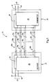
- FIG. 1 is a block diagram of two inverse multiplexers (IMUXs) coupled by multiple bi-directional physical communication links for passing ATM cell streams over the links.
- IMUXs inverse multiplexers
- FIG. 2 is a block diagram of three active links and one idle link between the IMUXs of FIG. 1 .
- FIG. 3 is timeline illustration of an ATM cell stream inverse multiplexed onto three data links of FIG. 2 .
- FIG. 4 is a timeline which shows the structure of an IMUX frame.
- a system 10 includes at least two inverse multiplexers (IMUXs) 20 and 22 coupled by multiple physical communication links 28 a-n .
- the IMUXs 20 and 22 are shown coupled by the physical communication links 28 a-n that are DS1 links, which carry bi-directional format data streams.
- Each link 28 carries data streams in either direction at a specified rate, which depends on the link's characteristics.
- each of the links 28 a-n carries one DS1 data stream 30 a-n in one direction and another DS1 data stream 32 a-n in the other direction.
- data streams of different rates and formats such as an E1, may be utilized.
- Each of the links 28 a-n can be a part of or pass through a public switched telephone network (PSTN). Furthermore, the links 28 a-n may be physically separate, for instance, using separate conductors in separate cables, or using different paths through the PSTN. Also, links 28 a-n may be physically combined for all or part of the path between IMUX 20 and 22 . For example, the data streams may be multiplexed onto a higher capacity physical communication link, such as a DS3 link. Additionally, links 28 a-n may exhibit different properties, including different transmission delays and different error rates.
- PSTN public switched telephone network
- the logical structure for the IMUX 20 and 22 can be implemented using a programmable processor, dedicated hardware, or both.
- a controller may, in some embodiments, be implemented as software processes executing on a programmable processor, under the control of software stored on a medium, such as a semiconductor read-only-memory (ROM).
- the controller may also include timing or clocking circuitry to determine the timing of data transfers between modules or unit. If the IMUX 20 and/or 22 includes a programmable processor, then software can be distributed to the IMUX 20 and/or 22 , for example on a physical removable medium or over a data network.
- the IMUX 20 includes a transmitter 24 and a receiver 26 .
- a transmitter 24 accepts an inbound ATM cell stream 44 over a physical ATM communication link 40 .
- the transmitter 24 of the IMUX 20 inverse multiplexes and sends the ATM cell stream 44 in the form of the DS1 data streams 32 a-n over the links 28 a-n , respectively, to the IMUX 22 .
- the IMUX 22 includes a transmitter 34 and the receiver 36 .
- the receiver 36 receives the DS1 data streams 32 a-n from the transmitter 24 of the IMUX 20 and multiplexes the DS1 data streams 32 a-n .
- the IMUX 22 can also receive an incoming ATM cell stream and inverse multiplex the incoming ATM cell stream over the links 28 a-n . More specifically, the transmitter 34 of the IMUX 22 accepts an inbound ATM cell stream 54 over a physical ATM communication link 50 .
- the transmitter 34 inverse multiplexes the ATM cell stream 54 in the form of DS1 data streams 30 a-n over a selected number of the links 28 a-n , respectively, that are then received by the receiver 26 of the IMUX 20 ; the receiver 26 multiplexes the DS1 data streams 30 a-n to form an outbound ATM cell stream 42 transmitted over the ATM communication link 40 .
- the IMUXs 20 and 22 can be configured to use any number of the links 28 a-n .
- the DS1 data streams 32 a-n on the links 28 a-n respectively, each terminate at the receiver 36 of the IMUX 22 , where an ATM cell stream 52 is reconstructed and sent on the ATM communication link 50 .
- the ATM cells that are received at the receivers 26 and 36 from the links 28 a-n must be multiplexed by the receivers 26 and 36 in the same order that the ATM cells were received at the transmitters 20 and 22 from the ATM communication links 40 and 50 , respectively. Accordingly, a number of links from the links 28 a-n must be selected, synchronized, and trained to operate at an optimal rate. Typically, the number of links that are selected from the links 28 a-n depends on the data rate that the customer requests, the physical characteristics of each of the links 28 a-n , and the number of available links. Based on these factors and other criteria, the optimal rate for each group of selected links 28 is selected.
- each link 28 various factors are considered, including the characteristics of each link 28 . For example, if four links between IMUX 20 and 22 are selected, such as links 28 a-d , to carry the inverse multiplexed ATM cell stream, then four links are trained at the optimal rate. Calculation of the selected optimal rate is subject of U.S. application Ser. No. 09/751,581 titled “Method and System for Establishing Link Bit Rate for Inverse Multiplexed Data Streams” on Dec. 29, 2000 and incorporated herein by reference.
- the selected optimal rate for any given link will be the same as the selected optimal rate for all of the other links and will depend on the characteristics of the links. Thus, the selected optimal rate should not exceed the maximum transmission rate of any one of the links 28 . Additionally, the selected optimal rate for each link may result in less than all of the available links being utilized.
- IMUXs 20 and 22 are shown, for illustration purposes, with four links 28 a-d selected and available to carry the ATM cell streams 44 and 54 between the IMUX 20 and the IMUX 22 .
- four links are shown, it will be apparent to those skilled in the art that any number of links can be used to carry ATM cell streams between the IMUX 20 and the IMUX 22 .
- the intent is to illustrate various embodiments; it not intended to limit the scope and spirit of invention as claimed herein.
- the data traffic is carried between the IMUXs 20 and 22 by the links 28 a-d .
- the characteristics of each of the links are determined. It is the characteristics of the selected links 28 a-d that will determine at what rate each of the lines will be trained and if all of the links 28 a-d will be used.
- each of the links 28 a-d can carry a rate of 2 Mbps
- only three of the four links 28 a-d are needed to carry the data between the IMUXs 20 and 22 .
- three of the links, such as links 28 a-c are trained to operate at the 2 Mbps rate and carry the data as active links between the IMUXs 20 and 22 .
- the fourth available link such as link 28 d
- the fourth available link is also trained to operate at the 2 Mbps rate, but acts as an idle link. Accordingly, if any one of the three active links 28 a-c fails, then the idle link 28 d can be used to immediately carry the traffic and, thereby, avoid the down time associated with having to retrain the failed links or add and train new links.
- the ATM data stream is shown after being inverse multiplexed onto a plurality of links 28 a-c in frames 60 , 62 , 64 , 66 , 68 , and 70 .
- the frames 60 and 62 can include ATM cells 72 a-d some of which may be an idle ATM cell that was inserted when ATM cell were not available to be insert into the frame 60 , cyclic redundancy check (CRC) cells 76 , detection cells 78 , and various other cells used for line detection and possible sequencing information, as will be discussed below.
- CRC cyclic redundancy check
- the detection cell 78 can vary in length and frequency of insertion.
- the detection cell 78 may be eight byte or sixty-four bits in length and appear after ever eight ATM cells.
- the detection cell 78 may be four bytes in length and appear after every four ATM cells.
- the overhead resulting from inserting the detection cell 78 is about 8 bytes or 1% of the total payload per frame 60 .
- the detection cell 78 will contain a predetermined pattern that is known at the both ends of the link 28 . Accordingly, error can be detected much faster and sooner because the detection cells, such as detection cell 78 , are insert frequently and repeatedly into each frame with a known content.
- the detection cell 78 may also include sequencing information that can further be used to enhance error detection.
- each frame such as frame 60
- the frames are carried in sequential 24-byte data payloads of DS1 frames 80 a-n , which provide a 1.536 Mbps payload data rate.
- the frame 60 is not necessarily aligned with the DS1 frames 80 ; the first byte of the frame 60 does not necessarily begin at the first byte of a payload of the DS1 frame 80 a.
- Each frame carries eight ATM cells 72 .
- Each ATM cell 72 is either an unmodified ATM cell that was received on inbound ATM cell stream 44 (or 54 ), or is an idle ATM cells inserted at the IMUX 20 or 22 because an ATM cells was not available to fill the frame 60 .
- the first byte of the frame 60 is a frame alignment word (FAW) 82 , that includes a 7-bit frame alignment word and a 1-bit far end block error (FEBE) indicator.
- FAW frame alignment word
- FEBE far end block error
- the frame 60 includes an ID byte 84 , which includes a 2-bit line identifier, and a 1-bit “line active” indicator.
- the line identifier is an index, numbered from 0 for the first DS1 data stream, the DS1 data stream 30 a in this example, to 3 for the fourth DS1 data stream, the DS1 data stream 30 d in the example of FIG. 2 .
- the line identifiers are used by the receiver to identify the order in which the receiver should assemble the ATM cells onto the outbound ATM cell stream, thereby avoiding reliance on proper physical identification of the physical communication lines carrying each of the DS1 data streams.
- each frame in tabular form, is as follows:
- the cell sequence numbers of ATM cells 72 are determined from frame sequence number (FSN) 86 , which is typically at byte 427 in the frame 60 .
Abstract
Description
| TABLE 1 |
| Frame structure |
| Frame byte | Frame bit | Number | |
| number | number | of bits | Description |
| 1 | 1-7 | 7 | Frame alignment word |
| 1 | 8 | 1 | Far end block error (FEBE) |
| indicator | |||
| 2-54 | 9-432 | 424 | ATM cell 1 |
| 55-107 | 433-856 | 424 | ATM cell 2 |
| 108-160 | 857-1280 | 424 | ATM cell 3 |
| 161-213 | 1281-1703 | 424 | ATM cell 4 |
| 214-266 | 1704-2128 | 424 | ATM cell 5 |
| 267-319 | 2129-2552 | 424 | ATM cell 6 |
| 320-372 | 2553-2976 | 424 | ATM cell 7 |
| 373-425 | 2977-3400 | 424 | ATM cell 8 |
| 426 | 3401-3404 | 4 | Reserved |
| 426 | 3405 | 1 | Available under software control |
| 426 | 3406 | 1 | “Line active” indicator |
| 426 | 3407-3408 | 2 | Line identification |
| 427 | 3409-3416 | 8 | Frame sequence number (FSN) |
| 428 | 3417-3422 | 6 | Cyclic redundancy check (CRC-6) |
| 428 | 3423 | 1 | Remote alarm indication |
| 428 | 3424 | 1 | Reserved |
Claims (3)
Priority Applications (1)
| Application Number | Priority Date | Filing Date | Title |
|---|---|---|---|
| US09/752,089 US6928056B2 (en) | 2000-12-29 | 2000-12-29 | System and method for distribution of a data stream from high-to-low-to-high bandwidth links |
Applications Claiming Priority (1)
| Application Number | Priority Date | Filing Date | Title |
|---|---|---|---|
| US09/752,089 US6928056B2 (en) | 2000-12-29 | 2000-12-29 | System and method for distribution of a data stream from high-to-low-to-high bandwidth links |
Publications (2)
| Publication Number | Publication Date |
|---|---|
| US20020122439A1 US20020122439A1 (en) | 2002-09-05 |
| US6928056B2 true US6928056B2 (en) | 2005-08-09 |
Family
ID=25024826
Family Applications (1)
| Application Number | Title | Priority Date | Filing Date |
|---|---|---|---|
| US09/752,089 Expired - Fee Related US6928056B2 (en) | 2000-12-29 | 2000-12-29 | System and method for distribution of a data stream from high-to-low-to-high bandwidth links |
Country Status (1)
| Country | Link |
|---|---|
| US (1) | US6928056B2 (en) |
Cited By (8)
| Publication number | Priority date | Publication date | Assignee | Title |
|---|---|---|---|---|
| US20040141505A1 (en) * | 2002-12-19 | 2004-07-22 | International Business Machines Corporation | Packet unstopper system for a parallel packet switch |
| US20050008041A1 (en) * | 2003-07-11 | 2005-01-13 | Zhangyi Wu | Apparatus and method for transmitting a DS3 signal over multiple twisted pair conductors |
| US20060246912A1 (en) * | 2003-04-14 | 2006-11-02 | Emanuele De Santis | Method for dimensioning a mobile telecommunications network |
| US20070189154A1 (en) * | 2006-02-10 | 2007-08-16 | Stratex Networks, Inc. | System and method for resilient wireless packet communications |
| US20080298396A1 (en) * | 2003-08-27 | 2008-12-04 | Telefonaktiebolaget Lm Ericsson (Publ) | Inverse Multiplexer with Tdm Bonding |
| US20090028156A1 (en) * | 2007-07-27 | 2009-01-29 | Fujitsu Limited | Frame transmission system and frame transmission apparatus |
| US20090067324A1 (en) * | 2007-09-06 | 2009-03-12 | Harris Stratex Networks Operating Corporation | Resilient Data Communications with Physical Layer Link Aggregation, Extended Failure Detection and Load Balancing |
| US20100246396A1 (en) * | 2007-05-24 | 2010-09-30 | Sergio Licardie | Dynamic Load Balancing for Layer-2 Link Aggregation |
Families Citing this family (2)
| Publication number | Priority date | Publication date | Assignee | Title |
|---|---|---|---|---|
| US20060198300A1 (en) * | 2005-03-03 | 2006-09-07 | Chia-Hsin Li | Multi-channel TCP connections with congestion feedback for video/audio data transmission |
| US8155156B2 (en) * | 2006-09-15 | 2012-04-10 | Alcatel Lucent | Synchronization recovery for multiple-link communications |
Citations (8)
| Publication number | Priority date | Publication date | Assignee | Title |
|---|---|---|---|---|
| US5608733A (en) * | 1994-11-29 | 1997-03-04 | Valle; Richard | ATM inverse multiplexing |
| US5617417A (en) * | 1994-09-07 | 1997-04-01 | Stratacom, Inc. | Asynchronous transfer mode communication in inverse multiplexing over multiple communication links |
| US5875192A (en) * | 1996-12-12 | 1999-02-23 | Pmc-Sierra Ltd. | ATM inverse multiplexing system |
| US6205142B1 (en) * | 1996-08-16 | 2001-03-20 | Nortel Networks Limited | Inverse multiplexing of digital data |
| US6222858B1 (en) * | 1999-02-10 | 2001-04-24 | Verizon Laboratories Inc. | Method of inverse multiplexing for ATM |
| US6574191B1 (en) * | 1998-08-09 | 2003-06-03 | Nec Corporation | Line switching system and method |
| US6621794B1 (en) * | 1999-02-18 | 2003-09-16 | Nokia Corporation | Method and apparatus for measuring the timing difference between physical IMA links and for delivering a time difference to the IMA layer |
| US6717960B1 (en) * | 2000-06-01 | 2004-04-06 | Agere Systems Inc. | Method for reconstructing an aggregate ATM cell stream and related device |
-
2000
- 2000-12-29 US US09/752,089 patent/US6928056B2/en not_active Expired - Fee Related
Patent Citations (9)
| Publication number | Priority date | Publication date | Assignee | Title |
|---|---|---|---|---|
| US5617417A (en) * | 1994-09-07 | 1997-04-01 | Stratacom, Inc. | Asynchronous transfer mode communication in inverse multiplexing over multiple communication links |
| US5608733A (en) * | 1994-11-29 | 1997-03-04 | Valle; Richard | ATM inverse multiplexing |
| US6205142B1 (en) * | 1996-08-16 | 2001-03-20 | Nortel Networks Limited | Inverse multiplexing of digital data |
| US5875192A (en) * | 1996-12-12 | 1999-02-23 | Pmc-Sierra Ltd. | ATM inverse multiplexing system |
| US6680954B1 (en) * | 1996-12-12 | 2004-01-20 | Pmc-Sierra, Ltd. | ATM inverse multiplexing system |
| US6574191B1 (en) * | 1998-08-09 | 2003-06-03 | Nec Corporation | Line switching system and method |
| US6222858B1 (en) * | 1999-02-10 | 2001-04-24 | Verizon Laboratories Inc. | Method of inverse multiplexing for ATM |
| US6621794B1 (en) * | 1999-02-18 | 2003-09-16 | Nokia Corporation | Method and apparatus for measuring the timing difference between physical IMA links and for delivering a time difference to the IMA layer |
| US6717960B1 (en) * | 2000-06-01 | 2004-04-06 | Agere Systems Inc. | Method for reconstructing an aggregate ATM cell stream and related device |
Cited By (29)
| Publication number | Priority date | Publication date | Assignee | Title |
|---|---|---|---|---|
| US7391766B2 (en) * | 2002-12-19 | 2008-06-24 | International Business Machines Corporation | Packet unstopper system for a parallel packet switch |
| US20040141505A1 (en) * | 2002-12-19 | 2004-07-22 | International Business Machines Corporation | Packet unstopper system for a parallel packet switch |
| US20060246912A1 (en) * | 2003-04-14 | 2006-11-02 | Emanuele De Santis | Method for dimensioning a mobile telecommunications network |
| US7433692B2 (en) * | 2003-04-14 | 2008-10-07 | Telecom Italia S.P.A. | Method for dimensioning a mobile telecommunications network |
| US7738511B2 (en) * | 2003-07-11 | 2010-06-15 | Hubbell Incorporated | Apparatus and method for transmitting a DS3 signal over multiple twisted pair conductors |
| US20050008041A1 (en) * | 2003-07-11 | 2005-01-13 | Zhangyi Wu | Apparatus and method for transmitting a DS3 signal over multiple twisted pair conductors |
| US7852881B2 (en) * | 2003-08-27 | 2010-12-14 | Telefonaktiebolaget L M Ericsson (Publ) | Inverse multiplexer with TDM bonding |
| US20080298396A1 (en) * | 2003-08-27 | 2008-12-04 | Telefonaktiebolaget Lm Ericsson (Publ) | Inverse Multiplexer with Tdm Bonding |
| US11916722B2 (en) | 2006-02-10 | 2024-02-27 | Aviat U.S., Inc. | System and method for resilient wireless packet communications |
| US9712378B2 (en) | 2006-02-10 | 2017-07-18 | Aviat U.S., Inc. | System and method for resilient wireless packet communications |
| US20070189154A1 (en) * | 2006-02-10 | 2007-08-16 | Stratex Networks, Inc. | System and method for resilient wireless packet communications |
| US11570036B2 (en) | 2006-02-10 | 2023-01-31 | Aviat U.S., Inc. | System and method for resilient wireless packet communications |
| US11165630B2 (en) | 2006-02-10 | 2021-11-02 | Aviat U.S., Inc. | System and method for resilient wireless packet communications |
| US8693308B2 (en) * | 2006-02-10 | 2014-04-08 | Aviat U.S., Inc. | System and method for resilient wireless packet communications |
| US10498584B2 (en) | 2006-02-10 | 2019-12-03 | Aviat U.S., Inc. | System and method for resilient wireless packet communications |
| US8988981B2 (en) | 2006-02-10 | 2015-03-24 | Aviat U.S., Inc. | System and method for resilient wireless packet communications |
| US10091051B2 (en) | 2006-02-10 | 2018-10-02 | Aviat U.S., Inc. | System and method for resilient wireless packet communications |
| US20100246396A1 (en) * | 2007-05-24 | 2010-09-30 | Sergio Licardie | Dynamic Load Balancing for Layer-2 Link Aggregation |
| US8264959B2 (en) | 2007-05-24 | 2012-09-11 | Harris Stratex Networks Operating Corporation | Dynamic load balancing for layer-2 link aggregation |
| US20090028156A1 (en) * | 2007-07-27 | 2009-01-29 | Fujitsu Limited | Frame transmission system and frame transmission apparatus |
| US7936791B2 (en) * | 2007-07-27 | 2011-05-03 | Fujitsu Limited | Frame transmission system and frame transmission apparatus |
| US9521036B2 (en) | 2007-09-06 | 2016-12-13 | Harris Stratex Networks, Inc. | Resilient data communications with physical layer link aggregation, extended failure detection and load balancing |
| US9929900B2 (en) | 2007-09-06 | 2018-03-27 | Aviat Networks, Inc. | Resilient data communications with physical layer link aggregation, extended failure detection and load balancing |
| US9294943B2 (en) | 2007-09-06 | 2016-03-22 | Harris Stratex Networks, Inc. | Resilient data communications with physical layer link aggregation, extended failure detection and load balancing |
| US10164874B2 (en) | 2007-09-06 | 2018-12-25 | Aviat Networks, Inc. | Resilient data communications with physical layer link aggregation, extended failure detection and load balancing |
| US8774000B2 (en) | 2007-09-06 | 2014-07-08 | Harris Stratex Networks, Inc. | Resilient data communications with physical layer link aggregation, extended failure detection and load balancing |
| US8264953B2 (en) | 2007-09-06 | 2012-09-11 | Harris Stratex Networks, Inc. | Resilient data communications with physical layer link aggregation, extended failure detection and load balancing |
| US11558285B2 (en) | 2007-09-06 | 2023-01-17 | Aviat U.S., Inc. | Resilient data communications with physical layer link aggregation, extended failure detection and load balancing |
| US20090067324A1 (en) * | 2007-09-06 | 2009-03-12 | Harris Stratex Networks Operating Corporation | Resilient Data Communications with Physical Layer Link Aggregation, Extended Failure Detection and Load Balancing |
Also Published As
| Publication number | Publication date |
|---|---|
| US20020122439A1 (en) | 2002-09-05 |
Similar Documents
| Publication | Publication Date | Title |
|---|---|---|
| US5274635A (en) | Method and apparatus for aligning a digital communication data stream across a cell network | |
| AU723092B2 (en) | Minicell sequence number count | |
| US11659072B2 (en) | Apparatus for adapting a constant bit rate client signal into the path layer of a telecom signal | |
| US5970072A (en) | System and apparatus for telecommunications bus control | |
| EP1006751B1 (en) | Flow control of frame based data over a synchronous digital network | |
| US4413337A (en) | Time division switching system for circuit mode and packet mode lines | |
| US6038231A (en) | Data suppression and regeneration | |
| US6963533B2 (en) | Method and system for establishing link bit rate for inverse multiplexed data streams | |
| US7046623B2 (en) | Fault recovery system and method for inverse multiplexed digital subscriber lines | |
| US7254134B2 (en) | Systems for transferring various data types across an ATM network | |
| US6928056B2 (en) | System and method for distribution of a data stream from high-to-low-to-high bandwidth links | |
| US6195346B1 (en) | Method and system for processing an HDLC message | |
| US7508846B2 (en) | Physical capacity aggregation system and method | |
| US7075944B1 (en) | Accommodation frame and transmission device of different data traffics on common carrier wave | |
| US5606558A (en) | Method of and devices for transmitting in ATM cells information supplied in the form of a series of distinct entities for a given application | |
| US20040133925A1 (en) | Method for transmitting information stream corresponding transmission system transmitter receiver and computer product | |
| US20020181441A1 (en) | Facilitating inverse multiplexing over asynchronous transfer mode via communication links having disparate data transmission rates | |
| EP0979566B1 (en) | Data suppression and regeneration | |
| US7042845B1 (en) | System and method for time division multiplexed switching of data using a high-speed packet switch | |
| US7272778B2 (en) | Method and systems for improving test of data transmission in multi-channel systems | |
| US7408939B1 (en) | Method and apparatus for transport of fractional datastreams over frame-based transport systems | |
| US6381249B1 (en) | Tandem pass through in a switched call | |
| GB2256350A (en) | Variable data rate channels for digital networks | |
| JP3577715B2 (en) | ATM communication system and ATM multi-link communication method | |
| US6694472B1 (en) | Error correction for frames carried over multiple networks |
Legal Events
| Date | Code | Title | Description |
|---|---|---|---|
| AS | Assignment |
Owner name: NOKIA NETWORKS OY, FINLAND Free format text: ASSIGNMENT OF ASSIGNORS INTEREST;ASSIGNOR:EVANS, DAVID J.;REEL/FRAME:011673/0603 Effective date: 20010119 |
|
| AS | Assignment |
Owner name: NOKIA OYJ, FINLAND Free format text: MERGER;ASSIGNOR:NOKIA NETWORKS OY;REEL/FRAME:018855/0758 Effective date: 20011001 |
|
| AS | Assignment |
Owner name: WI-LAN, INC., ONTARIO Free format text: ASSIGNMENT OF ASSIGNORS INTEREST;ASSIGNOR:NOKIA OYJ;REEL/FRAME:018875/0925 Effective date: 20070212 |
|
| FPAY | Fee payment |
Year of fee payment: 4 |
|
| FPAY | Fee payment |
Year of fee payment: 8 |
|
| REMI | Maintenance fee reminder mailed | ||
| AS | Assignment |
Owner name: QUARTERHILL INC., CANADA Free format text: MERGER AND CHANGE OF NAME;ASSIGNORS:WI-LAN INC.;QUARTERHILL INC.;REEL/FRAME:042914/0894 Effective date: 20170601 |
|
| AS | Assignment |
Owner name: WI-LAN INC., CANADA Free format text: ASSIGNMENT OF ASSIGNORS INTEREST;ASSIGNOR:QUARTERHILL INC.;REEL/FRAME:043167/0655 Effective date: 20170601 |
|
| LAPS | Lapse for failure to pay maintenance fees |
Free format text: PATENT EXPIRED FOR FAILURE TO PAY MAINTENANCE FEES (ORIGINAL EVENT CODE: EXP.) |
|
| STCH | Information on status: patent discontinuation |
Free format text: PATENT EXPIRED DUE TO NONPAYMENT OF MAINTENANCE FEES UNDER 37 CFR 1.362 |
|
| FP | Lapsed due to failure to pay maintenance fee |
Effective date: 20170809 |