US6913098B2 - Sub-reamer for bi-center type tools - Google Patents
Sub-reamer for bi-center type tools Download PDFInfo
- Publication number
- US6913098B2 US6913098B2 US10/301,049 US30104902A US6913098B2 US 6913098 B2 US6913098 B2 US 6913098B2 US 30104902 A US30104902 A US 30104902A US 6913098 B2 US6913098 B2 US 6913098B2
- Authority
- US
- United States
- Prior art keywords
- reamer
- diameter
- sub
- section
- tool
- Prior art date
- Legal status (The legal status is an assumption and is not a legal conclusion. Google has not performed a legal analysis and makes no representation as to the accuracy of the status listed.)
- Expired - Lifetime, expires
Links
- 238000005553 drilling Methods 0.000 claims description 12
- 230000000295 complement effect Effects 0.000 claims description 4
- 230000000712 assembly Effects 0.000 claims 1
- 238000000429 assembly Methods 0.000 claims 1
- 230000035515 penetration Effects 0.000 description 11
- 239000003381 stabilizer Substances 0.000 description 6
- 238000000034 method Methods 0.000 description 5
- 229910003460 diamond Inorganic materials 0.000 description 4
- 239000010432 diamond Substances 0.000 description 4
- 230000015572 biosynthetic process Effects 0.000 description 3
- 238000005755 formation reaction Methods 0.000 description 3
- 239000000463 material Substances 0.000 description 3
- 229910000831 Steel Inorganic materials 0.000 description 2
- 238000004519 manufacturing process Methods 0.000 description 2
- 239000010959 steel Substances 0.000 description 2
- 238000010276 construction Methods 0.000 description 1
- -1 e.g. Substances 0.000 description 1
- 230000002708 enhancing effect Effects 0.000 description 1
- 230000005484 gravity Effects 0.000 description 1
- 230000001788 irregular Effects 0.000 description 1
- 239000002184 metal Substances 0.000 description 1
- 238000012986 modification Methods 0.000 description 1
- 230000004048 modification Effects 0.000 description 1
- XLYOFNOQVPJJNP-UHFFFAOYSA-N water Substances O XLYOFNOQVPJJNP-UHFFFAOYSA-N 0.000 description 1
Images


Classifications
-
- E—FIXED CONSTRUCTIONS
- E21—EARTH DRILLING; MINING
- E21B—EARTH DRILLING, e.g. DEEP DRILLING; OBTAINING OIL, GAS, WATER, SOLUBLE OR MELTABLE MATERIALS OR A SLURRY OF MINERALS FROM WELLS
- E21B10/00—Drill bits
- E21B10/26—Drill bits with leading portion, i.e. drill bits with a pilot cutter; Drill bits for enlarging the borehole, e.g. reamers
- E21B10/265—Bi-center drill bits, i.e. an integral bit and eccentric reamer used to simultaneously drill and underream the hole
Definitions
- the present invention generally relates to drill bits useful for drilling oil, gas and water wells and methods for manufacturing such bits. More specifically, the present invention relates to a bi-center bit or two-piece bi-center bit which includes a sub-reamer section to aid in enhancing stability of the tool when rotated in the borehole.
- Bit and/or string instability probably occurs much more often than is readily apparent by reference to immediately noticeable problems. However, when such instability is severe, it places high stress on drilling equipment that includes not only drill bits but other downhole tools and the drill string in general. Common problems caused by such instability may include, but are not limited to, excessive torque, directional drilling control problems, and coring problems.
- one presently commercially available drill bit includes reinforced polycrystalline diamond compact (“PDC”) members that are strengthened by use of a fairly large taper or frustoconical contour on the PDC member.
- the taper angle in this tool is smaller than the backrake angle of the cutter to allow the cutter to cut into the formation at a desired angle.
- PDC polycrystalline diamond compact
- this design makes the PDC cutters stronger so as to reduce cutter damage, it does not solve the primary problem of bit instability.
- drill string problems, directional drilling control problems, and excessive torque problems remain.
- the drill bits made in this manner are more expensive and less resistant to abrasive wear as compared to the same drill bit made with standard cutters.
- bit whirl is a very complicated process that includes many types of bit movement patterns or modes of motion wherein the bit typically does not remain centered within the borehole.
- the solution is based on the premise that it is impossible to design and build a perfectly balanced bit. Therefore, an intentionally imbalanced bit is provided in a manner that improves bit stability.
- One drawback to this method is that for it to perform properly in the borehole, the bit forces must be the dominant force acting on the bit.
- These bits are generally designed to provide for a cutting force imbalance that may range about 500 to 2000 pounds depending on bit size and type.
- Unfortunately there are many cases where gravity or string movements create forces larger than the designed cutting force imbalance and therefore become the dominant bit forces. In such cases, the intentionally designed imbalance is ineffective to prevent the tool from becoming unstable and whirling in operation in the borehole.
- Penetration limiters work to prevent excessive cutter penetration into the formation that can lead to bit whirl or cutter damage. These devices may act to prevent not only bit whirl but also prevent radial bit movement or tilting problems that occur when drilling forces are not balanced. Furthermore, penetration limiters reduce bit rate of penetration of used too extensively but do not significantly improve stability of used too sparingly. Due to the variety of different applications, it is frequently difficult to determine to what extent penetration limiters should ve used.
- Bi-center bits have been used sporadically for over two decades as an alternative to undereamers.
- a desirable aspect to the bi-center bit is its ability to pass through a small hole and then drill a hole of a greater diameter.
- Problems associated with the bi-center bit include those of a short life due to irregular wear patterns and excessive wear, the creation of a smaller than expected hole size and overall poor directional characteristics.
- penetration limiters prevent disadvantages in the reduction of the rate of penetration when a high number of limiters is used.
- geometry of a bi-center bit limits the number of positions for penetration limiters on one side of the bit. Placing more penetration limiters on one side of the bit can cause a force imbalance that makes the bit less stable.
- the bi-center bit has yet to realize its potential as a reliable alternative to undereaming.
- the present invention addresses the above identified and other disadvantages usually associated with the instability and poor wear characteristics associated with drill bits, and more particularly, bi-center type downhole drilling tools.
- the downhole tool of the present invention generally comprises a proximal end adapted to be operably coupled to the drill string, and a distal end.
- the proximal end typically comprises a threaded pin.
- a pilot bit is formed about the distal end face and includes a plurality of cutting elements, e.g., PDC cutting elements.
- a reamer section is formed on one side or quadrant of the body between the threaded pin and the pilot section. This reamer section also includes cutting elements disposed about one or more cutting blades or upsets. These cutting blades, if more than one, are configured about a radial arc of less than 180 degrees.
- a sub-reamer section is positioned between the pilot and the reamer section.
- the sub-reamer section includes cutting blades or upsets also radially distributed in an arc of at least 180 degrees, using the axis of rotation “AA” as the center, where the end points of these cutter blades extend to a distance from “AA” equal to one-half of the diameter of the maximum tool size.
- the cutting blades can be oriented about any radial position vis-a-vis the reamer section.
- a second embodiment of the invention incorporates the same pilot and reamer sections as described in association with the first embodiment.
- the sub-reamer section is provided with cutting blades where the maximum distance of the endpoints of these blades as measured from “AA” varies depending on the position of the blades vis-a-vis the reamer section.
- the endpoints of the cutter blades extend a maximum distance from “AA” equal to one-half of the reamer drill diameter, but do not exceed one-half of the tool pass-through diameter, as measured from the pass-through axis “AB”.
- These blades preferably are oriented in a radial arc about the sub-reamer section which exceeds 180 degrees.
- the sub-reamer section is provided with cutting blades which define endpoints where the distance of these endpoints from “AA” varies depending on the position of the cutting blades vis-a-vis the reamer section.
- the endpoints of these blades extend to a maximum distance from “AA” which is equal to one-half of the tool pass-through diameter, which is measured from the pass-through axis “AB”.
- the cutting blades describe a radial arc of less than 180 degrees, where this arc is disposed opposite the reamer section.
- the present invention has a number of advantages over the prior art.
- One such advantage is enhanced stability in the borehole during a variety of operating conditions.
- Another advantage is improved wear characteristics of the tool.
- a pilot hole be drilled with another drilling tool before the bi-center is used or in the middle of a bi-center run.
- Conventional bi-centers can do this only if the pilot hole is the same size as the bi-center pilot bit or smaller. If the pilot hole is larger than the bi-center pilot bit then the bi-center will produce an undersized hole (the pilot bit will not center the bi-center in the hole). In most of these applications, the pilot hole is larger than the bi-center pilot, eliminating the use of the bi-center and forcing the use of less efficient tools. Since the sub-reamer has a larger cutting diameter than the pilot bit, a bi-center with a sub-reamer can be used in a pilot hole that is equal to or smaller than the cutting diameter of the sub-reamer.
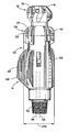
- FIG. 1 is a side view of a conventional bi-center drill bit
- FIG. 2 is a schematic view of the relative forces acting on a bi-center tool
- FIG. 3 is a side view of one embodiment of the bi-center tool of the present invention illustrating a sub-reamer section
- FIG. 4 illustrates an end view of the embodiment illustrated in FIG. 3 illustrating the pass-through diameter, the maximum tool diameter and the sub-reamer diameter;
- FIG. 5 is a schematic end view representation of a first preferred embodiment of the invention illustrating the reamer drill diameter, the tool pass-through diameter, the maximum tool size and the sub-reamer drill diameter;
- FIG. 6 is a side view of the embodiment illustrated in FIG. 5 ;
- FIG. 7 illustrates a second preferred embodiment of the invention also illustrating the reamer drill diameter, pass-through diameter, maximum tool size and sub-reamer drill diameter;
- FIG. 8 is a side view of the embodiment illustrated in FIG. 7 ;
- FIG. 9 illustrates a third preferred embodiment of the invention also illustrating the reamer drill diameter, pass-through diameter, maximum tool size and sub-reamer drill diameter.
- FIG. 10 is a side view of the embodiment illustrated in FIG. 9 .
- FIG. 1 depicts a conventional bi-center drill bit.
- a bit body 2 manufactured from steel or other hard metal, has a threaded pin 4 at its proximal end for connection in the drill string (not shown), and a pilot bit 3 defining an operating end face 6 at its opposite or distal end.
- a reamer section 5 is integrally formed with the body 2 between the pin 4 and the pilot bit 3 and defines a second operating face.
- pilot bit 3 is transversed by a number of upsets in the form of ribs or blades 8 radiating from the lower central area of the pilot bit 3 and extending across the distal most portion and up along the lower side surfaces of said bit 3 .
- Blades 8 are provided with a plurality of cutting elements 10 which may include polycrystalline diamond compacts (“PDC”).
- PDC polycrystalline diamond compacts
- the pilot bit 3 defines a gauge or stabilizer section which includes stabilizer ribs or kickers 12 , each of which is continuous with a respective one of the upsets 8 .
- Stabilizer ribs 12 contact the wall of the borehole (not shown) that has been drilled by the rotation of operating end face 6 and thus function to centralize and stabilize the tool and to help control its vibration within the borehole.
- a bi-center tool such as the one illustrated in FIG. 1 is inherently unstable in operation in the borehole. While a variety of designs and manufacturing techniques have been implemented to improve stability, these techniques have in some occasions been at the expense of optimum tool performance.
- FIG. 2 schematically illustrates the forces acting on a bi-center downhole tool during its operation in the borehole.
- the reamer section 5 exerts a large radial force in the direction indicated by arrow “A”.
- the pilot bit 3 can be designed to create an oppositely disposed force, here represented by arrow “B”, the comparatively smaller size of the operating face of the pilot 3 versus that of the reamer 5 translates into a force imbalance where “B ⁇ A”. Accordingly, a lesser but still significant resultant force is created away from the reamer section 5 in the direction indicated by arrow “A.” This imbalance of forces creates instability of the tool as it is rotated in the borehole.
- FIGS. 3-4 illustrate a general embodiment of the bi-center bit of the present invention.
- FIG. 3 illustrates a bit body 20 which again may be milled from a high-strength material, e.g., steel.
- the bit body defines a proximal and a distal end.
- a threaded pin 32 is formed about the proximal end whereas a pilot bit section 12 is formed about the distal end.
- a reamer section 14 is formed intermediate the pilot section 12 and the proximal end.
- Each of the pilot 12 and reamer 14 sections include one or more radial cutting blades 16 and 46 , respectively. Each of these cutting blades includes an endpoint 17 . Each of these cutting blades is also provided with one or more cutting elements, 18 and 48 , respectively, as described above in relation to a standard bi-center bit.
- the cutting elements may be made of a polycrystalline diamond compact or other material suitable for cutting through formations.
- the tool 20 defines a maximum tool diameter “MTD” (See FIG. 4 ).
- the maximum tool diameter “MTD” is that diameter measured from the rotational axis “AA” to the offside 35 of the reamer section 14 .
- the maximum tool diameter “MTD” therefore defines the largest permissible diameter of a tool positioned above or below the reamer section 14 that will enable the tool to be rotated in the borehole in an unobstructed manner.
- the tool 20 also defines a reamer drill diameter “RDD”.
- the reamer drill diameter “RDD” is that maximum diameter which the sub-reamer defines when rotated in the borehole about the rotational axis “AA”.
- a sub-reamer section 30 is disposed intermediate the pilot 12 and reamer sections 14 , as illustrated.
- the sub-reamer section 30 is also provided with one or more cutting blades 33 which are adapted to carry cutting elements 39 .
- the endpoints 31 of those blades are positioned at specific locations based on maximum tool diameter, pass-through diameter, and the reamer drill diameter.
- the rotational axis “AA” is that axis about which the tool 20 is rotated when not in casing.
- the tool 20 also defines a pass-through axis “AB”.
- the pass-through axis is that axis about which the tool is rotated when in casing.
- the rotation of the tool about the pass-through axis “AB” defines a pass-through diameter designated “PTD”.
- FIGS. 5-6 A first embodiment of the present invention may been seen by reference to FIGS. 5-6 .
- a bi-center tool 100 which includes a pilot bit section 102 and a reamer section 104 which are oriented about the tool in the fashion described above with respect to the general embodiment.
- the tool 100 defines a rotational axis “AA” and a maximum tool diameter “MTD”, as also defined above in relation to the general embodiment.
- a sub-reamer 108 is positioned intermediate of the pilot 102 and reamer 104 sections.
- the sub-reamer 108 is provided with a plurality of cutting blades 110 which define endpoints 111 which extend to a distance less than or equal to the maximum tool diameter “MTD”, as measured from the rotational axis “AA”.
- These cutting blades 110 are radially distributed in an arc greater than or equal to 180 degrees about the sub-reamer 180 .
- endpoints which extend the same distance from “AA” and generally extend about the full 360 degrees of the sub-reamer section 108 .
- Each of the cutting blades 110 may include one or more cutting elements 113 , e.g., PDC cutting elements, which may be affixed to cutting blades 110 in a conventional fashion.
- This embodiment has particular application in the use of a mid-reamer is used where the pilot bit is significantly smaller than the maximum tool size.
- FIGS. 7-8 A second embodiment of the invention may be seen by reference to FIGS. 7-8 .
- a bi-center tool 140 which includes a pilot section 142 , a reamer section 144 and a sub-reamer section 150 whose respective orientation has been described above.
- Tool 140 defines a rotational axis “AA” and a pass-through axis “AB”.
- the rotation of the tool about the pass-through axis “AB” defines a pass-through diameter “PTD”.
- the maximum tool diameter “MTD” and reamer drill diameter “RDD,” as defined above, are also illustrated.
- the cutting blades on the reamer section 144 describe an arc which further defines a midpoint “Q.”
- This midpoint “Q” can be determined by bisecting the linear distance between the endpoint 161 on the leading edge 160 of the first blade 162 and the endpoint 163 on the trailing edge 166 of the last blade 168 , as illustrated.
- the sub-reamer section 150 is provided with a number of cutting blades 152 , each of which define endpoints 151 .
- Blades 152 on the sub-reamer 150 are formed in an arc where this arc is centered about a line passing through rotational axis “AA” and midpoint “Q”.
- the intersection of the reamer drill diameter “RDD” and the pass-through diameter “PTD” defines two points of contact which are collectively designated 160 (See FIG. 7 ). These contact points 160 divide an end-section of the tool 140 into two different zones or regions. Zone 1 is that zone or region opposite the reamer section 144 and is disposed between contact points 160 . Zone 2 is complimentary to Zone 1 and is thus aligned about reamer section 144 and centered about midpoint “Q”.
- sub-reamer section 150 includes a plurality of cutting blades or upsets 152 which are radially oriented about the tool.
- the endpoints 151 of these cutting blades 152 is determined by their position relative to Zones 1 and 2.
- Those blades 152 situated in Zone 1 have endpoints which do not extend beyond the pass-through diameter “PTD”.
- the endpoints of all cutting blades 152 situated in Zone 2 do not radially extend beyond the reamer drill diameter “RDD”.
- cutting blades 152 extend radially in an arc of at least 180 degrees. In a second preferred embodiment, no cutting blades 152 on the sub-reamer section 150 are disposed directly opposite the main reamer blades. Main reamer blades are those blades whose endpoints extend to the reamer drill diameter (RDD).
- RDD reamer drill diameter
- FIGS. 9-10 A third embodiment of the invention is illustrated at FIGS. 9-10 in which is disclosed a bi-center downhole tool 200 which includes a pilot section 202 , reamer section 204 and sub-reamer section 212 , as described above in relation to the prior embodiments.
- Tool 200 defines a rotational axis “AA” and a pass-through axis “AB”, as illustrated in both FIGS. 9-10 .
- the tool defines a maximum tool diameter as indicated at “MTD”.
- the rotation of the tool about the pass-through axis “AB” defines a pass-through diameter “PTD”.
- the rotation of the reamer section 204 about the rotational axis defines a reamer drill diameter “RDD”. (See FIG. 9 ).
- the cutting blades or upsets 206 disposed on the reamer section 204 describe an arc which further defines a midpoint “Q”.
- this midpoint “Q” is also determined by bisecting the linear distance between the endpoint of the leading edge 220 of the first blade 222 and the endpoint of the trailing edge 226 of the last blade 230 , as illustrated.
- the sub-reamer section 206 is provided with a number of cutting blades 212 which define endpoints 207 . Blades on the sub-reamer are formed in a radial arc where this arc is centered about a line passing through rotational axis “AA” and midpoint “Q”.
- Zone 1 is formed opposite the reamer section 14 , where Zone 2 is that zone complementary to Zone 1 and centered about midpoint “Q.”
- all cutting blades 212 disposed on the sub-reamer section 206 are disposed in Zone 1 and define a radial arc of less than 180 degrees.
- the endpoints 213 of these blades 212 does not extend beyond the pass-through diameter “PTD”.
- the following example demonstrates the utility of the patented invention:
- the bi-center tool used is a 105 ⁇ 8 ⁇ 121 ⁇ 4 (pass through diameter ⁇ drill diameter).
- a conventional bi-center would typically have an 8′′ diameter pilot bit.
- a bi-center with a sub-reamer can be designed with a sub-reamer that has a cutting diameter of 83 ⁇ 4.
- the conventional bi-center can ream open the section of cored hole but create a hole that is smaller than the desired 121 ⁇ 4 for the entire 200 feet of the cored hole.
- the bi-center which includes the sub-reamer can create a 121 ⁇ 4 inch hole in this section of cored hole because the 83 ⁇ 4 inch sub-reamer is able to center the bi-center in the cored hole.
Abstract
Description
Claims (11)
Priority Applications (1)
| Application Number | Priority Date | Filing Date | Title |
|---|---|---|---|
| US10/301,049 US6913098B2 (en) | 2002-11-21 | 2002-11-21 | Sub-reamer for bi-center type tools |
Applications Claiming Priority (1)
| Application Number | Priority Date | Filing Date | Title |
|---|---|---|---|
| US10/301,049 US6913098B2 (en) | 2002-11-21 | 2002-11-21 | Sub-reamer for bi-center type tools |
Publications (2)
| Publication Number | Publication Date |
|---|---|
| US20040099448A1 US20040099448A1 (en) | 2004-05-27 |
| US6913098B2 true US6913098B2 (en) | 2005-07-05 |
Family
ID=32324457
Family Applications (1)
| Application Number | Title | Priority Date | Filing Date |
|---|---|---|---|
| US10/301,049 Expired - Lifetime US6913098B2 (en) | 2002-11-21 | 2002-11-21 | Sub-reamer for bi-center type tools |
Country Status (1)
| Country | Link |
|---|---|
| US (1) | US6913098B2 (en) |
Cited By (9)
| Publication number | Priority date | Publication date | Assignee | Title |
|---|---|---|---|---|
| US7350596B1 (en) | 2006-08-10 | 2008-04-01 | Attaya James S | Methods and apparatus for expanding the diameter of a borehole |
| US20100089659A1 (en) * | 2008-10-09 | 2010-04-15 | National Oilwell Varco, L.P. | Drilling Tool |
| US20100108396A1 (en) * | 2008-11-03 | 2010-05-06 | National Oilwell Varco, L.P. | Drilling Tool |
| US20100218996A1 (en) * | 2009-02-27 | 2010-09-02 | Conocophillips Company | Directional sidetrack well drilling system |
| CN101899952A (en) * | 2008-10-09 | 2010-12-01 | 瑞德海可洛格英国有限公司 | Drilling tool |
| US9410379B2 (en) | 2011-12-27 | 2016-08-09 | National Oilwell DHT, L.P. | Downhole cutting tool |
| US9534448B2 (en) * | 2013-10-31 | 2017-01-03 | Halliburton Energy Services, Inc. | Unbalance force identifiers and balancing methods for drilling equipment assemblies |
| US11208847B2 (en) | 2017-05-05 | 2021-12-28 | Schlumberger Technology Corporation | Stepped downhole tools and methods of use |
| US11441360B2 (en) | 2020-12-17 | 2022-09-13 | National Oilwell Varco, L.P. | Downhole eccentric reamer tool and related systems and methods |
Families Citing this family (26)
| Publication number | Priority date | Publication date | Assignee | Title |
|---|---|---|---|---|
| BRPI0410463B1 (en) * | 2003-05-21 | 2015-08-25 | Shell Int Research | Drill bit to drill a drill hole in an object |
| US8678111B2 (en) | 2007-11-16 | 2014-03-25 | Baker Hughes Incorporated | Hybrid drill bit and design method |
| US20090272582A1 (en) | 2008-05-02 | 2009-11-05 | Baker Hughes Incorporated | Modular hybrid drill bit |
| US20100155146A1 (en) * | 2008-12-19 | 2010-06-24 | Baker Hughes Incorporated | Hybrid drill bit with high pilot-to-journal diameter ratio |
| WO2010088489A1 (en) * | 2009-01-30 | 2010-08-05 | Baker Hughes Incorporated | Methods, systems, and tool assemblies for distributing weight-on-bit between a pilot earth-boring rotary drill bit and a reamer device |
| US8141664B2 (en) | 2009-03-03 | 2012-03-27 | Baker Hughes Incorporated | Hybrid drill bit with high bearing pin angles |
| US8459378B2 (en) * | 2009-05-13 | 2013-06-11 | Baker Hughes Incorporated | Hybrid drill bit |
| US8157026B2 (en) | 2009-06-18 | 2012-04-17 | Baker Hughes Incorporated | Hybrid bit with variable exposure |
| WO2011035051A2 (en) | 2009-09-16 | 2011-03-24 | Baker Hughes Incorporated | External, divorced pdc bearing assemblies for hybrid drill bits |
| US8448724B2 (en) * | 2009-10-06 | 2013-05-28 | Baker Hughes Incorporated | Hole opener with hybrid reaming section |
| US8191635B2 (en) | 2009-10-06 | 2012-06-05 | Baker Hughes Incorporated | Hole opener with hybrid reaming section |
| MX340468B (en) | 2010-06-29 | 2016-07-08 | Baker Hughes Incorporated * | Drill bits with anti-tracking features. |
| US8978786B2 (en) | 2010-11-04 | 2015-03-17 | Baker Hughes Incorporated | System and method for adjusting roller cone profile on hybrid bit |
| SG192650A1 (en) | 2011-02-11 | 2013-09-30 | Baker Hughes Inc | System and method for leg retention on hybrid bits |
| US9782857B2 (en) | 2011-02-11 | 2017-10-10 | Baker Hughes Incorporated | Hybrid drill bit having increased service life |
| US8851205B1 (en) | 2011-04-08 | 2014-10-07 | Hard Rock Solutions, Llc | Method and apparatus for reaming well bore surfaces nearer the center of drift |
| EP2780532B1 (en) | 2011-11-15 | 2020-01-08 | Baker Hughes, a GE company, LLC | Hybrid drill bits having increased drilling efficiency |
| US10107039B2 (en) | 2014-05-23 | 2018-10-23 | Baker Hughes Incorporated | Hybrid bit with mechanically attached roller cone elements |
| CN104314473B (en) * | 2014-08-27 | 2017-09-05 | 西南石油大学 | The PDC drill bit instrument of eccentric swing rotation can be achieved |
| US11428050B2 (en) | 2014-10-20 | 2022-08-30 | Baker Hughes Holdings Llc | Reverse circulation hybrid bit |
| CN104747084B (en) * | 2015-04-03 | 2017-06-13 | 核工业井巷建设集团公司 | A kind of air drill reaming bit suitable for underwater rock plug burst construction |
| US10557311B2 (en) | 2015-07-17 | 2020-02-11 | Halliburton Energy Services, Inc. | Hybrid drill bit with counter-rotation cutters in center |
| CA3075388A1 (en) | 2017-09-09 | 2019-03-14 | Extreme Technologies, Llc | Well bore conditioner and stabilizer |
| US11408230B2 (en) | 2017-10-10 | 2022-08-09 | Extreme Technologies, Llc | Wellbore reaming systems and devices |
| CN110374512A (en) * | 2019-06-17 | 2019-10-25 | 河北锐石钻头制造有限公司 | A kind of concentric type twin-stage double speed PDC drill bit |
| CN114131076B (en) * | 2021-12-04 | 2023-06-23 | 深圳市瑞鹏飞模具有限公司 | PLC-controlled hardware workpiece precision drilling equipment |
Citations (13)
| Publication number | Priority date | Publication date | Assignee | Title |
|---|---|---|---|---|
| US2124414A (en) * | 1936-04-18 | 1938-07-19 | Otto B Goldman | Well drilling bit |
| US5497842A (en) | 1995-04-28 | 1996-03-12 | Baker Hughes Incorporated | Reamer wing for enlarging a borehole below a smaller-diameter portion therof |
| US5678644A (en) | 1995-08-15 | 1997-10-21 | Diamond Products International, Inc. | Bi-center and bit method for enhancing stability |
| US5765653A (en) | 1996-10-09 | 1998-06-16 | Baker Hughes Incorporated | Reaming apparatus and method with enhanced stability and transition from pilot hole to enlarged bore diameter |
| US5957223A (en) | 1997-03-05 | 1999-09-28 | Baker Hughes Incorporated | Bi-center drill bit with enhanced stabilizing features |
| US5992548A (en) | 1995-08-15 | 1999-11-30 | Diamond Products International, Inc. | Bi-center bit with oppositely disposed cutting surfaces |
| US6206117B1 (en) * | 1997-04-02 | 2001-03-27 | Baker Hughes Incorporated | Drilling structure with non-axial gage |
| US6269893B1 (en) | 1999-06-30 | 2001-08-07 | Smith International, Inc. | Bi-centered drill bit having improved drilling stability mud hydraulics and resistance to cutter damage |
| US6340064B2 (en) | 1999-02-03 | 2002-01-22 | Diamond Products International, Inc. | Bi-center bit adapted to drill casing shoe |
| US6386302B1 (en) | 1999-09-09 | 2002-05-14 | Smith International, Inc. | Polycrystaline diamond compact insert reaming tool |
| US6394200B1 (en) | 1999-10-28 | 2002-05-28 | Camco International (U.K.) Limited | Drillout bi-center bit |
| US6397958B1 (en) | 1999-09-09 | 2002-06-04 | Baker Hughes Incorporated | Reaming apparatus and method with ability to drill out cement and float equipment in casing |
| US6659207B2 (en) * | 1999-06-30 | 2003-12-09 | Smith International, Inc. | Bi-centered drill bit having enhanced casing drill-out capability and improved directional stability |
-
2002
- 2002-11-21 US US10/301,049 patent/US6913098B2/en not_active Expired - Lifetime
Patent Citations (16)
| Publication number | Priority date | Publication date | Assignee | Title |
|---|---|---|---|---|
| US2124414A (en) * | 1936-04-18 | 1938-07-19 | Otto B Goldman | Well drilling bit |
| US5497842A (en) | 1995-04-28 | 1996-03-12 | Baker Hughes Incorporated | Reamer wing for enlarging a borehole below a smaller-diameter portion therof |
| US5678644A (en) | 1995-08-15 | 1997-10-21 | Diamond Products International, Inc. | Bi-center and bit method for enhancing stability |
| US5992548A (en) | 1995-08-15 | 1999-11-30 | Diamond Products International, Inc. | Bi-center bit with oppositely disposed cutting surfaces |
| US5765653A (en) | 1996-10-09 | 1998-06-16 | Baker Hughes Incorporated | Reaming apparatus and method with enhanced stability and transition from pilot hole to enlarged bore diameter |
| US6116356A (en) | 1996-10-09 | 2000-09-12 | Baker Hughes Incorporated | Reaming apparatus and method with enhanced stability and transition from pilot hole to enlarged bore diameter |
| US5957223A (en) | 1997-03-05 | 1999-09-28 | Baker Hughes Incorporated | Bi-center drill bit with enhanced stabilizing features |
| US6206117B1 (en) * | 1997-04-02 | 2001-03-27 | Baker Hughes Incorporated | Drilling structure with non-axial gage |
| US6340064B2 (en) | 1999-02-03 | 2002-01-22 | Diamond Products International, Inc. | Bi-center bit adapted to drill casing shoe |
| US6269893B1 (en) | 1999-06-30 | 2001-08-07 | Smith International, Inc. | Bi-centered drill bit having improved drilling stability mud hydraulics and resistance to cutter damage |
| US6464024B2 (en) | 1999-06-30 | 2002-10-15 | Smith International, Inc. | Bi-centered drill bit having improved drilling stability, mud hydraulics and resistance to cutter damage |
| US6659207B2 (en) * | 1999-06-30 | 2003-12-09 | Smith International, Inc. | Bi-centered drill bit having enhanced casing drill-out capability and improved directional stability |
| US6386302B1 (en) | 1999-09-09 | 2002-05-14 | Smith International, Inc. | Polycrystaline diamond compact insert reaming tool |
| US6397958B1 (en) | 1999-09-09 | 2002-06-04 | Baker Hughes Incorporated | Reaming apparatus and method with ability to drill out cement and float equipment in casing |
| US6609580B2 (en) * | 1999-09-09 | 2003-08-26 | Smith International, Inc. | Polycrystalline diamond compact insert reaming tool |
| US6394200B1 (en) | 1999-10-28 | 2002-05-28 | Camco International (U.K.) Limited | Drillout bi-center bit |
Cited By (14)
| Publication number | Priority date | Publication date | Assignee | Title |
|---|---|---|---|---|
| US7350596B1 (en) | 2006-08-10 | 2008-04-01 | Attaya James S | Methods and apparatus for expanding the diameter of a borehole |
| US20100089659A1 (en) * | 2008-10-09 | 2010-04-15 | National Oilwell Varco, L.P. | Drilling Tool |
| CN101899951B (en) * | 2008-10-09 | 2014-10-22 | 里德海卡洛格英国有限公司 | Drill bit |
| CN101899952B (en) * | 2008-10-09 | 2014-01-15 | 瑞德海可洛格英国有限公司 | Drilling tool |
| CN101899952A (en) * | 2008-10-09 | 2010-12-01 | 瑞德海可洛格英国有限公司 | Drilling tool |
| US7958953B2 (en) * | 2008-10-09 | 2011-06-14 | National Oilwell Varco, L.P. | Drilling tool |
| US8042625B2 (en) * | 2008-11-03 | 2011-10-25 | National Oilwell Varco, L.P. | Drilling tool |
| US20100108396A1 (en) * | 2008-11-03 | 2010-05-06 | National Oilwell Varco, L.P. | Drilling Tool |
| US8430187B2 (en) * | 2009-02-27 | 2013-04-30 | Conocophillips Company | Directional sidetrack well drilling system |
| US20100218996A1 (en) * | 2009-02-27 | 2010-09-02 | Conocophillips Company | Directional sidetrack well drilling system |
| US9410379B2 (en) | 2011-12-27 | 2016-08-09 | National Oilwell DHT, L.P. | Downhole cutting tool |
| US9534448B2 (en) * | 2013-10-31 | 2017-01-03 | Halliburton Energy Services, Inc. | Unbalance force identifiers and balancing methods for drilling equipment assemblies |
| US11208847B2 (en) | 2017-05-05 | 2021-12-28 | Schlumberger Technology Corporation | Stepped downhole tools and methods of use |
| US11441360B2 (en) | 2020-12-17 | 2022-09-13 | National Oilwell Varco, L.P. | Downhole eccentric reamer tool and related systems and methods |
Also Published As
| Publication number | Publication date |
|---|---|
| US20040099448A1 (en) | 2004-05-27 |
Similar Documents
| Publication | Publication Date | Title |
|---|---|---|
| US6913098B2 (en) | Sub-reamer for bi-center type tools | |
| US5992548A (en) | Bi-center bit with oppositely disposed cutting surfaces | |
| US6474425B1 (en) | Asymmetric diamond impregnated drill bit | |
| US5678644A (en) | Bi-center and bit method for enhancing stability | |
| US5558170A (en) | Method and apparatus for improving drill bit stability | |
| US5803196A (en) | Stabilizing drill bit | |
| US6629476B2 (en) | Bi-center bit adapted to drill casing shoe | |
| US6904984B1 (en) | Stepped polycrystalline diamond compact insert | |
| EP3521549B1 (en) | Shaped cutting elements for earth-boring tools and earth boring tools including such cutting elements | |
| US7000715B2 (en) | Rotary drill bits exhibiting cutting element placement for optimizing bit torque and cutter life | |
| US5957223A (en) | Bi-center drill bit with enhanced stabilizing features | |
| US7318492B2 (en) | Rotary drill bit | |
| EP2129860B1 (en) | Method of forming pockets for receiving drill bit cutting elements | |
| CA1214159A (en) | Drill bit and improved cutting element | |
| NO330003B1 (en) | Hollow opener with fixed blade and fixed cutter | |
| US20030173114A1 (en) | Enhanced offset stabilization for eccentric reamers | |
| US6575256B1 (en) | Drill bit with lateral movement mitigation and method of subterranean drilling | |
| US10697248B2 (en) | Earth-boring tools and related methods | |
| US20010045305A1 (en) | Two stage drill bit | |
| US7690446B2 (en) | Single cone rock bit having inserts adapted to maintain hole gage during drilling | |
| EP3837416B1 (en) | Downhole tools with improved arrangement of cutters | |
| US20110100714A1 (en) | Backup cutting elements on non-concentric earth-boring tools and related methods | |
| EP1039095B1 (en) | Downhole drill bit | |
| US10954721B2 (en) | Earth-boring tools and related methods | |
| CA3099676C (en) | Earth boring tools having fixed blades and varying sized rotatable cutting structres and related methods |
Legal Events
| Date | Code | Title | Description |
|---|---|---|---|
| AS | Assignment |
Owner name: DIAMOND PRODUCTS INTERNATIONAL, INC., TEXAS Free format text: ASSIGNMENT OF ASSIGNORS INTEREST;ASSIGNORS:FIELDER, COY M.;SILVA, ROGERIO;REEL/FRAME:013514/0152 Effective date: 20021119 |
|
| AS | Assignment |
Owner name: REEDHYCALOG, L.P., TEXAS Free format text: MERGER;ASSIGNOR:DIAMOND PRODUCTS INTERNATIONAL, INC.;REEL/FRAME:015972/0543 Effective date: 20050415 |
|
| AS | Assignment |
Owner name: WELLS FARGO BANK, TEXAS Free format text: SECURITY AGREEMENT;ASSIGNOR:REEDHYCALOG, L.P.;REEL/FRAME:016087/0681 Effective date: 20050512 |
|
| STCF | Information on status: patent grant |
Free format text: PATENTED CASE |
|
| AS | Assignment |
Owner name: REED HYCALOG, UTAH, LLC., TEXAS Free format text: RELEASE OF PATENT SECURITY AGREEMENT;ASSIGNOR:WELLS FARGO BANK;REEL/FRAME:018463/0103 Effective date: 20060831 |
|
| FPAY | Fee payment |
Year of fee payment: 4 |
|
| FPAY | Fee payment |
Year of fee payment: 8 |
|
| FPAY | Fee payment |
Year of fee payment: 12 |