US6876660B1 - Method for implementing automatic protection switching (APS) using cell replication - Google Patents
Method for implementing automatic protection switching (APS) using cell replication Download PDFInfo
- Publication number
- US6876660B1 US6876660B1 US09/250,968 US25096899A US6876660B1 US 6876660 B1 US6876660 B1 US 6876660B1 US 25096899 A US25096899 A US 25096899A US 6876660 B1 US6876660 B1 US 6876660B1
- Authority
- US
- United States
- Prior art keywords
- crossbar
- data
- slot
- scheduler
- destination slot
- Prior art date
- Legal status (The legal status is an assumption and is not a legal conclusion. Google has not performed a legal analysis and makes no representation as to the accuracy of the status listed.)
- Expired - Lifetime
Links
Images


Classifications
-
- H—ELECTRICITY
- H04—ELECTRIC COMMUNICATION TECHNIQUE
- H04L—TRANSMISSION OF DIGITAL INFORMATION, e.g. TELEGRAPHIC COMMUNICATION
- H04L12/00—Data switching networks
- H04L12/28—Data switching networks characterised by path configuration, e.g. LAN [Local Area Networks] or WAN [Wide Area Networks]
- H04L12/42—Loop networks
- H04L12/437—Ring fault isolation or reconfiguration
Definitions
- the present invention is related to networks.
- the method and apparatus of the present invention relates to Automatic Protection Switching (APS) using cell replication.
- APS Automatic Protection Switching
- APS Automatic Protection Switching
- SONET Synchronous Optical Network
- linear APS modes There are three types of linear APS modes, namely, 1+1, 1:1 and 1:n. All three modes require that if any failures are detected in a working line, a switch to a protection line must be initiated in 10 msec and completed in 50 msec for a total of 60 msec.
- APS is implemented electrically through a multiplexer (MUX)/buffer combination on a line card.
- MUX multiplexer
- the disadvantages inherent in the current technology are many.
- the APS ports must be in predefined locations, typically adjacent to each other.
- the current scheme does not work at high speed signal transmissions. More specifically, although repeating signals at low speed is tolerable, the scheme breaks down at high speeds due to impedance mismatch and capacitive loading.
- a method for cell replication in which a request for data transmission and mapping information are received by a crossbar and a scheduler and are sent by one of a plurality of software configurable slot remap registers.
- the mapping information is indicative of a destination slot and a backup destination slot to which the data is to be transmitted.
- the method replicates the data by transmitting the data to the destination slot and to the backup destination slot when the data arrives at an input slot of the crossbar.
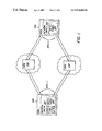
- FIG. 1 is a network diagram with an embodiment of a switch fabric with cell replication.
- FIG. 2 is a block diagram of an embodiment of a switch fabric.
- FIG. 3 is an exemplary block diagram of the switch fabric with a crossbar architecture.
- FIG. 4 is a switch plane with an embodiment of an APS cell replication feature.
- FIG. 5 illustrate exemplary registers.
- FIG. 6 is a flow chart showing the general steps of APS using cell replication.
- a switch fabric has a slot that can be “dual-homed” to two slots. For example, if slot X is dual homed to slot X and Y, then any traffic that is destined to X will also go to Y. To avoid programming errors, this feature stipulates that one of the dual-homed slots must be itself. In other words, it is an illegal operation if slot X is dual-homed to Y and Z, where X, Y and Z are different values.
- the dual homing feature is implemented through a switch fabric register referenced herein as a slot remap register that is under software control. The software may enable the feature on any slot at any time, disable the feature on any slot at any time and modify the slot numbers at any time.
- slot X When slot X is dual-homed to X and Y, a request that goes to either X or Y will be treated as if there is a request going to X and Y.
- a grant is issued to the requesting slot only if both requests (to X and Y) are granted. This applies to unicast and mulitcast traffic.
- FIG. 1 is a network diagram with an embodiment of a switch fabric with cell replication.
- a network is a collection of computers, printers, routers, switches and other devices that are able to communicate with each other over some transmission medium.
- Nodes in a network refer to an endpoint of a network connection or a junction common to two or more lines in a network.
- Nodes can be processors, controllers, or workstations.
- Nodes vary in routing and other functional capabilities and can be interconnected by links, and serve as control points in the network.
- Switch which is a chassis based, modular architecture having circuit boards configured to plug into the chassis.
- a switch is a device that allows a connection to be established as necessary and terminated when there is no longer a session to support.
- a network node 100 has a network switch 101 with a switch fabric 102 .
- the switch fabric 102 has an APS cell replication feature 150 with a 1+1 implementation where for every working line, there is a corresponding redundant protection line. Traffic is carried by both the working and the protection line simultaneously.
- a network node 104 also has a network switch 105 having a switch fabric 106 with an APS cell replication feature with a 1+1 implementation.
- the two intermediate nodes 108 and 110 do not need an APS implementation because they are protected on both sides of the network by the APS cell replication features 150 of nodes 100 and 104 .
- the APS cell replication feature can be implemented to protect physical lines between the network nodes.
- FIG. 2 is a block diagram of one embodiment of a switch fabric.
- a network switch 101 has three types of parts, namely a processor card 200 , a switch card 202 (switch fabric 102 ) and a line card 204 .
- the line card 204 interfaces traffic coming in and out of a physical port with the switch fabric 102 .
- the interface is accomplished through a switch fabric interface 205 that interfaces the switch fabric 102 with a line card 204 and a layer functions 207 which processes data received from and forwarded to the physical port through framers/transceivers 209 1 . . . 209 N into an appropriate format.
- a processor card 200 is a form of a line card 204 and has the Central Processing Unit (CPU) 203 , segmentation and reassembly (SAR) 211 and high level software.
- CPU Central Processing Unit
- SAR segmentation and reassembly
- Each switch card 202 has the APS cell replication feature and has of a number of switch planes 206 1 . . . 206 N , which are the basic elements of a switch fabric 102 .
- each switch plane 206 has a crossbar 213 and a scheduler 215 . Both the crossbar 213 and the scheduler 215 are discussed in detail in the text accompanying FIGS. 3 and 4 .
- the APS cell replication feature is implemented in the switch fabric 102 , more specifically through the crossbar 213 and the scheduler 215 .
- FIG. 3 is an exemplary block diagram of the switch fabric with a crossbar architecture.
- FIG. 3 is illustrated with ingress slots 300 and egress slots 302 , which are part of the same line card 204 , but logically separate.
- requests for transmission made for the traffic comprised of cells are sent to the switch planes 206 1 . . . 206 N of the switch fabric 102 .
- a switch plane 206 receiving a request determines whether to grant the request or not. If the switch plane 206 determines to grant the request, then in the next time slot the line card 204 submits a cell (also referred to herein as data) and the switch plane 206 switches the destination of the cell to an appropriate alternate destination.
- a cell also referred to herein as data
- the switch fabric 102 determines which requests to provide grants to. The traffic is then sent to the switch fabric 102 where the traffic is “switched” or “routed” to the appropriate destination slots.
- the APS cell replication feature repeats a connection using the switch fabric 102 . More specifically, a number of registers, referred to herein as slot remap registers, are programmed into each switch planes 206 1 . . . 206 N , such that when traffic is passed to an egress slot 1 (ES 1 ), the traffic is also copied to an egress slot 2 (ES 2 ) where ES 1 (active line) is protected by ES 2 (standby line).
- the APS cell replication feature repeats the connections logically through software control and there is no limitation on transmission speed. Additionally, since the APS cell replication feature is controlled logically through software control, a given line can protect “n” or any combination of lines, whereas with prior technology, lines physically next to each other were assigned to each other for APS protection.
- FIG. 4 is a switch plane with an embodiment of the APS cell replication feature.
- a switch plane having the APS cell replication feature may be implemented with a switch ASIC 400 .
- there are two entities within the switch plane 206 namely a crossbar 213 , which includes gates to direct traffic, and a scheduler 215 that controls the crossbar 213 .
- the scheduler 215 has N signal inputs 408 1 . . . 408 N and N signal outputs 410 1 . . . 410 N and provides control signals 406 1 . . . 406 N to the crossbar 213 .
- the signal inputs 408 1 . . . 408 N to the scheduler 215 are requests for data transmission through the crossbar 213
- the signal outputs 410 1 . . . 410 N are grants (i.e. acknowledgements to the requests).
- the crossbar 213 has N data in signals 412 1 . . . 412 N and N data out signals 414 1 . . . 414 N and is an N by N spatial crossbar that may have N concurrent events such as N data coming in and N data going out. Only data for which a request for transmission is granted by the scheduler 215 is processed through the crossbar 213 .
- Both the crossbar 213 and the scheduler 215 receive mapping information 422 from software configurable slot remap registers 416 1 . . . 416 N .
- Mapping information 422 identifies the data out destination slots 414 1 . . . 414 N to which data is to be transmitted through the crossbar 213 .
- each of the N slot remap registers 416 1 . . . 416 N corresponds with a sequential one of “data in” signals 412 1 . . . 412 N of the crossbar 213 .
- slot remap register 416 corresponds to data in signal 412 1 .
- the scheduler 215 When a request comes in to, for example, input slot 408 1 of the scheduler 215 , the scheduler 215 receives the corresponding mapping information 422 from the slot remap register 416 1 . The scheduler 215 then determines whether the destination slot and the backup destination slot as identified by the mapping information 422 for input slot 408 , are valid based on the result of arbitration (i.e., whether the destination slot and the backup destination slot are available). For example, the scheduler 215 may grant requests based on some type of priority scheme whereby a grant with the highest predetermined priority is granted a request first and so on. The form of arbitration to select which destination slot to grant next may vary and is not limited to a priority scheme based arbitration.
- the scheduler 215 transmits a control signal 406 to the crossbar 213 which indicates that 412 1 is permitted to send a cell to its intended destination slot and the backup destination slot. Additionally, an acknowledgment 418 is sent back to the source 420 of the request, such as an ingress line card.
- the crossbar 213 knows which route to take the data by the slot identified by the mapping information 422 .
- FIG. 5 illustrates exemplary slot remap registers.
- the four lower bits determine the identity of the current backup slot (i.e., “remap value”).
- Each register of the slot remap registers 416 1 . . . 416 N may correspond with one slot (one-to-one correspondence with 14 registers and 14 slots).
- the backup slot is assigned to 1 to N slots. In an alternate embodiment, a backup slot is assigned to one specific slot.
- the slot remap registers 416 1 . . . 416 N are software configurable. The setting of the slot remap registers 416 1 . . . 416 N may be changed at any given time, the effect of which will take place the next time count. There are two scenarios for which the slot remap registers 416 1 . . . 416 N may be reprogrammed to match slots with a changed backup slot. In one scenario, a system that is non-redundant is to be made redundant. In a second scenario, a system's network topology is changed, for instance, network topology may change as more connections are added to the system and connections are deleted due to an increase in network users.
- the topology of the user changes and the user may want to reconfigure the APS logic.
- the APS logic there are three options for the APS logic, namely, addition, deletion, or reconfiguration of the backup slots.
- the slot remap registers 416 1 . . . 416 N may be re-programmed accordingly.
- FIG. 6 is a flow diagram illustrating the general steps followed by one embodiment.
- a request comes in to the scheduler 215 .
- the scheduler 215 receives the corresponding mapping information 422 from the slot remap registers 416 1 . . . 416 N .
- the scheduler 215 determines whether the slot and the backup slot to grant the request to are valid (i.e., available). If the requests are not valid, then a grant will not be issued to the source of the request.
- the scheduler 215 transmits a control signal 406 to the crossbar 213 that indicates that the slot and the backup slot are available.
- the crossbar 213 transmits the data to its destination slot and replicates the data cell by transmitting the data to the duo-homed backup destination slot.
Abstract
Description
Claims (28)
Priority Applications (1)
| Application Number | Priority Date | Filing Date | Title |
|---|---|---|---|
| US09/250,968 US6876660B1 (en) | 1999-02-16 | 1999-02-16 | Method for implementing automatic protection switching (APS) using cell replication |
Applications Claiming Priority (1)
| Application Number | Priority Date | Filing Date | Title |
|---|---|---|---|
| US09/250,968 US6876660B1 (en) | 1999-02-16 | 1999-02-16 | Method for implementing automatic protection switching (APS) using cell replication |
Publications (1)
| Publication Number | Publication Date |
|---|---|
| US6876660B1 true US6876660B1 (en) | 2005-04-05 |
Family
ID=34375060
Family Applications (1)
| Application Number | Title | Priority Date | Filing Date |
|---|---|---|---|
| US09/250,968 Expired - Lifetime US6876660B1 (en) | 1999-02-16 | 1999-02-16 | Method for implementing automatic protection switching (APS) using cell replication |
Country Status (1)
| Country | Link |
|---|---|
| US (1) | US6876660B1 (en) |
Cited By (10)
| Publication number | Priority date | Publication date | Assignee | Title |
|---|---|---|---|---|
| US20020110136A1 (en) * | 2001-02-07 | 2002-08-15 | Junnosuke Wakai | Packet routing apparatus and a method of communicating a packet |
| US20030179749A1 (en) * | 2002-03-21 | 2003-09-25 | Mark Barry Ding Ken | System and method for providing protection of data communications in packet-based networks |
| US20060050631A1 (en) * | 2004-09-03 | 2006-03-09 | Akin Koyuncuoglu | Reconfigurable apparatus providing 1:N and 1:1 equipment redundancy for high speed broadband interfaces with 1‘and 1:N automatic protection switching |
| US20060104271A1 (en) * | 2004-11-17 | 2006-05-18 | Samsung Electronics Co., Ltd. | Method and system for switching packets in a communication network |
| US7065038B1 (en) * | 2001-02-28 | 2006-06-20 | Cisco Technology, Inc. | Automatic protection switching line card redundancy within an intermediate network node |
| US20070263532A1 (en) * | 2006-05-10 | 2007-11-15 | Sina Mirtorabi | Backup path convergence in the APS environment |
| CN100375461C (en) * | 2005-09-30 | 2008-03-12 | 烽火通信科技股份有限公司 | Method for carrying out VPR protection inversion in network |
| US7673070B1 (en) * | 2003-03-17 | 2010-03-02 | Network Equipment Technologies, Inc. | Method of sharing telecommunications node equipment facilities |
| US20110060862A1 (en) * | 2009-09-08 | 2011-03-10 | Lsi Corporation | Systems and Methods for Switchable Memory Configuration |
| US20120163375A1 (en) * | 1999-11-24 | 2012-06-28 | Juniper Networks, Inc. | Switching device |
Citations (11)
| Publication number | Priority date | Publication date | Assignee | Title |
|---|---|---|---|---|
| US5202994A (en) * | 1990-01-31 | 1993-04-13 | Hewlett-Packard Company | System and method for shadowing and re-mapping reserved memory in a microcomputer |
| US5751710A (en) * | 1996-06-11 | 1998-05-12 | Cisco Technology, Inc. | Technique for connecting cards of a distributed network switch |
| US5838924A (en) * | 1996-08-06 | 1998-11-17 | Lucent Technologies Inc | Asynchronous transfer mode (ATM) connection protection switching apparatus and method |
| US5903544A (en) * | 1996-04-05 | 1999-05-11 | Hitachi, Ltd. | Packet handler |
| US6044061A (en) * | 1998-03-10 | 2000-03-28 | Cabletron Systems, Inc. | Method and apparatus for fair and efficient scheduling of variable-size data packets in an input-buffered multipoint switch |
| US6208658B1 (en) * | 1998-09-25 | 2001-03-27 | Vertical Networks, Inc. | Systems and methods for multiple mode voice and data communications using intelligently bridged TDM and packet buses and methods for performing telephony and data functions using the same |
| US6272151B1 (en) * | 1994-05-19 | 2001-08-07 | Cisco Technology, Inc. | Scalable multimedia network |
| US6317426B1 (en) * | 1999-06-03 | 2001-11-13 | Fujitsu Network Communications, Inc. | Method and apparatus for hybrid protection in a switching network |
| US6317439B1 (en) * | 1999-06-03 | 2001-11-13 | Fujitsu Network Communications, Inc. | Architecture for a SONET line unit including optical transceiver, cross-connect and synchronization subsystem |
| US6351454B1 (en) | 1998-07-24 | 2002-02-26 | Cisco Technology, Inc. | Apparatus and method for maintaining packet ordering over parallel links of a crossbar based switch fabric |
| US6370112B1 (en) * | 1998-06-16 | 2002-04-09 | Lucent Technologies Inc. | Seamless path switchover in a connection-oriented packet network |
-
1999
- 1999-02-16 US US09/250,968 patent/US6876660B1/en not_active Expired - Lifetime
Patent Citations (12)
| Publication number | Priority date | Publication date | Assignee | Title |
|---|---|---|---|---|
| US5202994A (en) * | 1990-01-31 | 1993-04-13 | Hewlett-Packard Company | System and method for shadowing and re-mapping reserved memory in a microcomputer |
| US5301328A (en) * | 1990-01-31 | 1994-04-05 | Hewlett-Packard Company | System and method for shadowing and re-mapping reserved memory in a microcomputer |
| US6272151B1 (en) * | 1994-05-19 | 2001-08-07 | Cisco Technology, Inc. | Scalable multimedia network |
| US5903544A (en) * | 1996-04-05 | 1999-05-11 | Hitachi, Ltd. | Packet handler |
| US5751710A (en) * | 1996-06-11 | 1998-05-12 | Cisco Technology, Inc. | Technique for connecting cards of a distributed network switch |
| US5838924A (en) * | 1996-08-06 | 1998-11-17 | Lucent Technologies Inc | Asynchronous transfer mode (ATM) connection protection switching apparatus and method |
| US6044061A (en) * | 1998-03-10 | 2000-03-28 | Cabletron Systems, Inc. | Method and apparatus for fair and efficient scheduling of variable-size data packets in an input-buffered multipoint switch |
| US6370112B1 (en) * | 1998-06-16 | 2002-04-09 | Lucent Technologies Inc. | Seamless path switchover in a connection-oriented packet network |
| US6351454B1 (en) | 1998-07-24 | 2002-02-26 | Cisco Technology, Inc. | Apparatus and method for maintaining packet ordering over parallel links of a crossbar based switch fabric |
| US6208658B1 (en) * | 1998-09-25 | 2001-03-27 | Vertical Networks, Inc. | Systems and methods for multiple mode voice and data communications using intelligently bridged TDM and packet buses and methods for performing telephony and data functions using the same |
| US6317426B1 (en) * | 1999-06-03 | 2001-11-13 | Fujitsu Network Communications, Inc. | Method and apparatus for hybrid protection in a switching network |
| US6317439B1 (en) * | 1999-06-03 | 2001-11-13 | Fujitsu Network Communications, Inc. | Architecture for a SONET line unit including optical transceiver, cross-connect and synchronization subsystem |
Non-Patent Citations (1)
| Title |
|---|
| CISCO, 12012 Gigabit Switch Router Installation and Configuration Guide, publication, 1997, U.S. (also available on the "Documentation" website for Cisco Systems, Inc., http://www.cisco.com/univercd/cc/td/doc/product/core/cis12000/cis12012/fru/4343swfc.htm#xtocid227783, Feb. 29, 2001. |
Cited By (20)
| Publication number | Priority date | Publication date | Assignee | Title |
|---|---|---|---|---|
| US20120163375A1 (en) * | 1999-11-24 | 2012-06-28 | Juniper Networks, Inc. | Switching device |
| US9992133B2 (en) | 1999-11-24 | 2018-06-05 | Juniper Networks, Inc. | Switching device for routing packets through a network |
| US9479462B2 (en) | 1999-11-24 | 2016-10-25 | Juniper Networks, Inc. | Switching device |
| US8804709B2 (en) * | 1999-11-24 | 2014-08-12 | Juniper Networks, Inc. | Switching device |
| US20060126500A1 (en) * | 2001-02-07 | 2006-06-15 | Junnosuke Wakai | Packet routing apparatus and a method of communicating a packet |
| US7027390B2 (en) * | 2001-02-07 | 2006-04-11 | Hitachi, Ltd. | Packet routing apparatus and a method of communicating a packet |
| US20020110136A1 (en) * | 2001-02-07 | 2002-08-15 | Junnosuke Wakai | Packet routing apparatus and a method of communicating a packet |
| US7639604B2 (en) | 2001-02-07 | 2009-12-29 | Hitachi, Ltd. | Packet routing apparatus and a method of communicating a packet |
| US7065038B1 (en) * | 2001-02-28 | 2006-06-20 | Cisco Technology, Inc. | Automatic protection switching line card redundancy within an intermediate network node |
| US7251214B2 (en) * | 2002-03-21 | 2007-07-31 | Tropic Networks Inc. | System and method for providing protection of data communications in packet-based networks |
| US20030179749A1 (en) * | 2002-03-21 | 2003-09-25 | Mark Barry Ding Ken | System and method for providing protection of data communications in packet-based networks |
| US7673070B1 (en) * | 2003-03-17 | 2010-03-02 | Network Equipment Technologies, Inc. | Method of sharing telecommunications node equipment facilities |
| US7450494B2 (en) * | 2004-09-03 | 2008-11-11 | Cisco Technology, Inc. | Reconfigurable apparatus providing 1:N and 1:1 equipment redundancy for high speed broadband interfaces with 1+1 and 1:N automatic protection switching |
| US20060050631A1 (en) * | 2004-09-03 | 2006-03-09 | Akin Koyuncuoglu | Reconfigurable apparatus providing 1:N and 1:1 equipment redundancy for high speed broadband interfaces with 1‘and 1:N automatic protection switching |
| US20060104271A1 (en) * | 2004-11-17 | 2006-05-18 | Samsung Electronics Co., Ltd. | Method and system for switching packets in a communication network |
| US8279866B2 (en) * | 2004-11-17 | 2012-10-02 | Samsung Electronics Co., Ltd. | Method and system for switching packets in a communication network |
| CN100375461C (en) * | 2005-09-30 | 2008-03-12 | 烽火通信科技股份有限公司 | Method for carrying out VPR protection inversion in network |
| US20070263532A1 (en) * | 2006-05-10 | 2007-11-15 | Sina Mirtorabi | Backup path convergence in the APS environment |
| US8040795B2 (en) | 2006-05-10 | 2011-10-18 | Cisco Technology, Inc. | Backup path convergence in the APS environment |
| US20110060862A1 (en) * | 2009-09-08 | 2011-03-10 | Lsi Corporation | Systems and Methods for Switchable Memory Configuration |
Similar Documents
| Publication | Publication Date | Title |
|---|---|---|
| US5740346A (en) | System and method for dynamic network topology exploration | |
| US5469432A (en) | High-speed digital communications network | |
| US7058084B2 (en) | Multistage interconnect network combines back channel replies received from destinations into a single result and transmits to the source | |
| TWI458307B (en) | Method and system for an os virtualization-aware network interface card | |
| EP0430569B1 (en) | Fault tolerant interconnection networks | |
| WO2000027136A1 (en) | High performance crossbar switch | |
| US5724348A (en) | Efficient hardware/software interface for a data switch | |
| EP0273249A2 (en) | Fault tolerant switch with selectable operating modes | |
| US7111101B1 (en) | Method and system for port numbering in an interconnect device | |
| US20080240133A1 (en) | Communication device, communication system, and lag management table management method used therefor | |
| US11652881B2 (en) | Mirroring to multiple destinations using a monitoring function | |
| US20020107980A1 (en) | Computer system and method of communication between modules within computer system | |
| US20070070993A1 (en) | Butterfly network with switches set for two node disjoint paths and method for forming the paths | |
| US6876660B1 (en) | Method for implementing automatic protection switching (APS) using cell replication | |
| WO1990010984A1 (en) | Communication switching system | |
| US8194653B2 (en) | Data switching using soft configuration | |
| US7706259B2 (en) | Method for implementing redundant structure of ATCA (advanced telecom computing architecture) system via base interface and the ATCA system for use in the same | |
| EP1471698B1 (en) | Network fabric access device with multiple system side interfaces | |
| JP2000512112A (en) | Method for alternately switching transmission equipment for bidirectional transmission of ATM cells | |
| US6895024B1 (en) | Efficient implementation of 1+1 port redundancy through the use of ATM multicast | |
| JPH06261045A (en) | Method and apparatus for message communication | |
| US6661786B1 (en) | Service message system for a switching architecture | |
| DeHon et al. | Fault-tolerant design for multistage routing networks | |
| US20050021797A1 (en) | Method and system to control the communication of data between a plurality of interconnect devices | |
| US6034943A (en) | Adaptive communication node for use in an inter-processor communications system |
Legal Events
| Date | Code | Title | Description |
|---|---|---|---|
| AS | Assignment |
Owner name: CISCO TECHNOLOGY, INC., CALIFORNIA Free format text: ASSIGNMENT OF ASSIGNORS INTEREST;ASSIGNORS:HUGHES, DAVID A.;CHUI, FRANK H.;REEL/FRAME:013529/0007;SIGNING DATES FROM 20020829 TO 20020903 |
|
| AS | Assignment |
Owner name: CISCO TECHNOLOGY, INC. (A CORPORATION OF CALIFORNI Free format text: ASSIGNMENT OF ASSIGNORS INTEREST;ASSIGNOR:NGUYEN, QUANG H.;REEL/FRAME:013607/0180 Effective date: 20021219 |
|
| AS | Assignment |
Owner name: CISCO TECHNOLOGY, INC., A CORPORATION OF CALIFORNI Free format text: ASSIGNMENT OF ASSIGNORS INTEREST;ASSIGNORS:LAU, ONCHUEN D.;CHUI, FRANK H.;REEL/FRAME:013765/0833;SIGNING DATES FROM 20030207 TO 20030210 |
|
| STCF | Information on status: patent grant |
Free format text: PATENTED CASE |
|
| FPAY | Fee payment |
Year of fee payment: 4 |
|
| FEPP | Fee payment procedure |
Free format text: PAYOR NUMBER ASSIGNED (ORIGINAL EVENT CODE: ASPN); ENTITY STATUS OF PATENT OWNER: LARGE ENTITY |
|
| FPAY | Fee payment |
Year of fee payment: 8 |
|
| FPAY | Fee payment |
Year of fee payment: 12 |