US6870810B1 - Apparatus and method for managing network congestion - Google Patents
Apparatus and method for managing network congestion Download PDFInfo
- Publication number
- US6870810B1 US6870810B1 US09/554,840 US55484000A US6870810B1 US 6870810 B1 US6870810 B1 US 6870810B1 US 55484000 A US55484000 A US 55484000A US 6870810 B1 US6870810 B1 US 6870810B1
- Authority
- US
- United States
- Prior art keywords
- network
- network connections
- transmission
- threshold
- rejection
- Prior art date
- Legal status (The legal status is an assumption and is not a legal conclusion. Google has not performed a legal analysis and makes no representation as to the accuracy of the status listed.)
- Expired - Lifetime
Links
Images


Classifications
-
- H—ELECTRICITY
- H04—ELECTRIC COMMUNICATION TECHNIQUE
- H04L—TRANSMISSION OF DIGITAL INFORMATION, e.g. TELEGRAPHIC COMMUNICATION
- H04L12/00—Data switching networks
- H04L12/54—Store-and-forward switching systems
- H04L12/56—Packet switching systems
- H04L12/5601—Transfer mode dependent, e.g. ATM
-
- H—ELECTRICITY
- H04—ELECTRIC COMMUNICATION TECHNIQUE
- H04L—TRANSMISSION OF DIGITAL INFORMATION, e.g. TELEGRAPHIC COMMUNICATION
- H04L47/00—Traffic control in data switching networks
- H04L47/10—Flow control; Congestion control
-
- H—ELECTRICITY
- H04—ELECTRIC COMMUNICATION TECHNIQUE
- H04L—TRANSMISSION OF DIGITAL INFORMATION, e.g. TELEGRAPHIC COMMUNICATION
- H04L47/00—Traffic control in data switching networks
- H04L47/10—Flow control; Congestion control
- H04L47/12—Avoiding congestion; Recovering from congestion
- H04L47/125—Avoiding congestion; Recovering from congestion by balancing the load, e.g. traffic engineering
-
- H—ELECTRICITY
- H04—ELECTRIC COMMUNICATION TECHNIQUE
- H04L—TRANSMISSION OF DIGITAL INFORMATION, e.g. TELEGRAPHIC COMMUNICATION
- H04L47/00—Traffic control in data switching networks
- H04L47/10—Flow control; Congestion control
- H04L47/24—Traffic characterised by specific attributes, e.g. priority or QoS
- H04L47/2458—Modification of priorities while in transit
-
- H—ELECTRICITY
- H04—ELECTRIC COMMUNICATION TECHNIQUE
- H04L—TRANSMISSION OF DIGITAL INFORMATION, e.g. TELEGRAPHIC COMMUNICATION
- H04L47/00—Traffic control in data switching networks
- H04L47/10—Flow control; Congestion control
- H04L47/29—Flow control; Congestion control using a combination of thresholds
-
- H—ELECTRICITY
- H04—ELECTRIC COMMUNICATION TECHNIQUE
- H04L—TRANSMISSION OF DIGITAL INFORMATION, e.g. TELEGRAPHIC COMMUNICATION
- H04L47/00—Traffic control in data switching networks
- H04L47/10—Flow control; Congestion control
- H04L47/30—Flow control; Congestion control in combination with information about buffer occupancy at either end or at transit nodes
-
- H—ELECTRICITY
- H04—ELECTRIC COMMUNICATION TECHNIQUE
- H04L—TRANSMISSION OF DIGITAL INFORMATION, e.g. TELEGRAPHIC COMMUNICATION
- H04L47/00—Traffic control in data switching networks
- H04L47/10—Flow control; Congestion control
- H04L47/31—Flow control; Congestion control by tagging of packets, e.g. using discard eligibility [DE] bits
-
- H—ELECTRICITY
- H04—ELECTRIC COMMUNICATION TECHNIQUE
- H04L—TRANSMISSION OF DIGITAL INFORMATION, e.g. TELEGRAPHIC COMMUNICATION
- H04L47/00—Traffic control in data switching networks
- H04L47/10—Flow control; Congestion control
- H04L47/32—Flow control; Congestion control by discarding or delaying data units, e.g. packets or frames
- H04L47/323—Discarding or blocking control packets, e.g. ACK packets
-
- H—ELECTRICITY
- H04—ELECTRIC COMMUNICATION TECHNIQUE
- H04L—TRANSMISSION OF DIGITAL INFORMATION, e.g. TELEGRAPHIC COMMUNICATION
- H04L49/00—Packet switching elements
- H04L49/30—Peripheral units, e.g. input or output ports
- H04L49/3081—ATM peripheral units, e.g. policing, insertion or extraction
-
- H—ELECTRICITY
- H04—ELECTRIC COMMUNICATION TECHNIQUE
- H04L—TRANSMISSION OF DIGITAL INFORMATION, e.g. TELEGRAPHIC COMMUNICATION
- H04L69/00—Network arrangements, protocols or services independent of the application payload and not provided for in the other groups of this subclass
- H04L69/16—Implementation or adaptation of Internet protocol [IP], of transmission control protocol [TCP] or of user datagram protocol [UDP]
- H04L69/161—Implementation details of TCP/IP or UDP/IP stack architecture; Specification of modified or new header fields
-
- H—ELECTRICITY
- H04—ELECTRIC COMMUNICATION TECHNIQUE
- H04L—TRANSMISSION OF DIGITAL INFORMATION, e.g. TELEGRAPHIC COMMUNICATION
- H04L69/00—Network arrangements, protocols or services independent of the application payload and not provided for in the other groups of this subclass
- H04L69/16—Implementation or adaptation of Internet protocol [IP], of transmission control protocol [TCP] or of user datagram protocol [UDP]
- H04L69/163—In-band adaptation of TCP data exchange; In-band control procedures
-
- H—ELECTRICITY
- H04—ELECTRIC COMMUNICATION TECHNIQUE
- H04L—TRANSMISSION OF DIGITAL INFORMATION, e.g. TELEGRAPHIC COMMUNICATION
- H04L9/00—Cryptographic mechanisms or cryptographic arrangements for secret or secure communications; Network security protocols
- H04L9/40—Network security protocols
-
- H—ELECTRICITY
- H04—ELECTRIC COMMUNICATION TECHNIQUE
- H04Q—SELECTING
- H04Q11/00—Selecting arrangements for multiplex systems
- H04Q11/04—Selecting arrangements for multiplex systems for time-division multiplexing
- H04Q11/0428—Integrated services digital network, i.e. systems for transmission of different types of digitised signals, e.g. speech, data, telecentral, television signals
- H04Q11/0478—Provisions for broadband connections
-
- H—ELECTRICITY
- H04—ELECTRIC COMMUNICATION TECHNIQUE
- H04L—TRANSMISSION OF DIGITAL INFORMATION, e.g. TELEGRAPHIC COMMUNICATION
- H04L12/00—Data switching networks
- H04L12/54—Store-and-forward switching systems
- H04L12/56—Packet switching systems
- H04L12/5601—Transfer mode dependent, e.g. ATM
- H04L2012/5629—Admission control
- H04L2012/5631—Resource management and allocation
-
- H—ELECTRICITY
- H04—ELECTRIC COMMUNICATION TECHNIQUE
- H04L—TRANSMISSION OF DIGITAL INFORMATION, e.g. TELEGRAPHIC COMMUNICATION
- H04L12/00—Data switching networks
- H04L12/54—Store-and-forward switching systems
- H04L12/56—Packet switching systems
- H04L12/5601—Transfer mode dependent, e.g. ATM
- H04L2012/5638—Services, e.g. multimedia, GOS, QOS
- H04L2012/5646—Cell characteristics, e.g. loss, delay, jitter, sequence integrity
- H04L2012/5647—Cell loss
- H04L2012/5648—Packet discarding, e.g. EPD, PTD
-
- H—ELECTRICITY
- H04—ELECTRIC COMMUNICATION TECHNIQUE
- H04L—TRANSMISSION OF DIGITAL INFORMATION, e.g. TELEGRAPHIC COMMUNICATION
- H04L12/00—Data switching networks
- H04L12/54—Store-and-forward switching systems
- H04L12/56—Packet switching systems
- H04L12/5601—Transfer mode dependent, e.g. ATM
- H04L2012/5638—Services, e.g. multimedia, GOS, QOS
- H04L2012/5646—Cell characteristics, e.g. loss, delay, jitter, sequence integrity
- H04L2012/5651—Priority, marking, classes
-
- H—ELECTRICITY
- H04—ELECTRIC COMMUNICATION TECHNIQUE
- H04L—TRANSMISSION OF DIGITAL INFORMATION, e.g. TELEGRAPHIC COMMUNICATION
- H04L12/00—Data switching networks
- H04L12/54—Store-and-forward switching systems
- H04L12/56—Packet switching systems
- H04L12/5601—Transfer mode dependent, e.g. ATM
- H04L2012/5638—Services, e.g. multimedia, GOS, QOS
- H04L2012/5665—Interaction of ATM with other protocols
- H04L2012/5667—IP over ATM
-
- H—ELECTRICITY
- H04—ELECTRIC COMMUNICATION TECHNIQUE
- H04L—TRANSMISSION OF DIGITAL INFORMATION, e.g. TELEGRAPHIC COMMUNICATION
- H04L12/00—Data switching networks
- H04L12/54—Store-and-forward switching systems
- H04L12/56—Packet switching systems
- H04L12/5601—Transfer mode dependent, e.g. ATM
- H04L2012/5678—Traffic aspects, e.g. arbitration, load balancing, smoothing, buffer management
- H04L2012/5681—Buffer or queue management
- H04L2012/5682—Threshold; Watermark
-
- H—ELECTRICITY
- H04—ELECTRIC COMMUNICATION TECHNIQUE
- H04L—TRANSMISSION OF DIGITAL INFORMATION, e.g. TELEGRAPHIC COMMUNICATION
- H04L69/00—Network arrangements, protocols or services independent of the application payload and not provided for in the other groups of this subclass
- H04L69/16—Implementation or adaptation of Internet protocol [IP], of transmission control protocol [TCP] or of user datagram protocol [UDP]
Definitions
- the present invention relates to computer networks in general, and in particular to methods and apparatus for managing computer network congestion.
- TCP packet-switching protocols
- the effective throughput, or “goodput” (namely throughput that is “good” for the higher layer protocol)
- goodput namely throughput that is “good” for the higher layer protocol
- TCP over ATM can be very low when TCP packet cells are dropped by congested ATM switches over which TCP connections are established. This is due to the fact that while the loss of a single cell corrupts an entire packet, the rest of the cells belonging to the same corrupted packet are not necessarily dropped. These cells continue to consume network resources such as bandwidth and buffer space, unnecessarily increasing the chance that other cells may be dropped.
- PPD partial packet discard
- EPD electronic packet discard
- EPD is designed to prevent the leading cells of a packet in which a cell is dropped from being buffered and transmitted. This is done by setting a buffer threshold and testing the threshold to determine whether or not there is room in the buffer for the entire packet before buffering any packet cells. If the threshold is exceeded, all of the cells in the packet are dropped except for the last cell.
- a TCP packet loss can be detected by the sending device by detecting a time-out or by receiving 3 duplicate acknowledgments (ACKs).
- the sending device maintains an estimate of the maximum round-trip time of the connection.
- the sending device detects the packet loss and re-transmits the lost packet.
- the time during which the sending device waits for an ACK of a lost packet to arrive is referred to as a time-out.
- Most commercial TCP implementations set the time-out to be at least 2-3 seconds. Since typical data transfer times range from tens of milliseconds to several seconds, even a single time-out during the lifetime of a TCP connection results in significant performance degradation.
- a fast retransmit method has been developed to avoid time-outs. Since the receiving device acknowledges the highest in-order packet sequence number it has received so far, when it receives an out-of-order packet (due to a loss of a previous packet) it generates an ACK for the same highest in-order sequence number. Such an ACK is referred to as a duplicate ACK. Under the fast retransmit method, when the sending device receives three duplicate ACKS, the sending device considers the packet, which starts with the sequence number immediately after the number acknowledged by the duplicate ACKs, to be lost. Hence, the presumed missing packet is immediately retransmitted.
- Fast retransmit helps to minimize the recovery delay from a loss of a single packet if the TCP sending window size is large enough (i.e., larger than 4 packets).
- the sending device can usually recover from only the first packet loss using fast retransmit, whereas recovery from other losses generally only occurs after a time-out.
- a burst of losses has a very negative effect on the connection's throughput.
- PPD and EPD may conserve network resources for a given packet in which a cell is dropped, they offer no mechanism for maximizing network throughput by reducing the number of packets lost in a given TCP sending window for a given TCP connection.
- a mechanism referred to herein as BPD or “balanced packet discard” is provided for maximizing the total throughput of multiple TCP or other packet-switched connections sharing a common buffer space in an ATM or other cell-switching switch. This is achieved by minimizing the probability that a TCP connection will encounter a time-out. More specifically, when a packet of some connection is discarded, e.g., as a result of EPD or PPD mechanisms being invoked, the affected connection is given priority over other connections sharing the same buffer space.
- This priority is to avoid subsequent packet loss by the same connection by discarding packets of other connections, even if such discarding would not otherwise be required under PPD or EPD mechanisms.
- BPD thus spreads the effects of network congestion more evenly across multiple connections to improve the chances for recovery for each individual connection.
- a method for managing congestion on a network including establishing a buffer threshold bounding a first and a second buffer region, maintaining a rejection indicator for each of a plurality of network connections, and preventing the buffering of a transmission bound for a first of the plurality of network connections if the buffer threshold is exceeded, the rejection indicator of the first of the plurality of network connections indicates that no transmission bound for the first of the plurality of network connections was previously rejected since the threshold last became exceeded, and the rejection indicator of any other of the plurality of network connections indicates that a transmission bound for the other of the plurality of network connections was previously rejected since the threshold last became exceeded.
- the method includes rejecting the transmission bound for the first of the plurality of network connections.
- the method includes setting the rejection indicator of the first of the plurality of network connections to indicate that the transmission bound for the first of the plurality of network connections has been rejected.
- the method further includes counting the number of times that transmission buffering is performed for the first of the plurality of network connections subsequent to the setting of the rejection indicator of the first of the plurality of network connections, and setting the rejection indicator of the first of the plurality of network connections to indicate that no transmission has been rejected once the counting equals a predetermined value.
- the method includes setting any of the rejection indicators to indicate that no transmission has been rejected, the resetting occurs when the threshold is no longer exceeded.
- a method for managing congestion on a network including maintaining a maximum buffer allocation for each of a plurality of network connections, maintaining a rejection indicator for each of the plurality of network connections, increasing the maximum buffer allocation for a first of the plurality of network connections, and decreasing the maximum buffer allocation for at least a second of the plurality of network connections, the increasing and decreasing occur when the rejection indicator of the first of the plurality of network connections indicates that a transmission bound for the first of the plurality of network connections was previously rejected, and the rejection indicator of the second of the plurality of network connections indicates that no transmission bound for the second of the plurality of network connections was previously rejected.
- an aggregate of the increasing is substantially proportionate to an aggregate of the decreasing.
- the method includes establishing a buffer threshold bounding a first and a second buffer region for each of the plurality of network connections, maintaining a current buffer allocation for each of the plurality of network connections, and performing the increasing and decreasing steps when the current buffer allocation of the first of the plurality of network connections exceeds the buffer threshold of the first of the plurality of network connections.
- the method includes rejecting a transmission bound for the first of the plurality of network connections.
- the method includes setting the first rejection indicator to indicate that the transmission bound for the first of the plurality of network connections has been rejected.
- the method includes setting any of the rejection indicators to indicate that no transmission has been rejected, the resetting occurs when all of the rejection indicators indicate that a transmission has been rejected.
- network congestion management apparatus including a network switch connectable with a plurality of network connections and including a buffer having a first and a second buffer region, a threshold indicator for monitoring a threshold intermediate the first and second buffer regions, and a rejection indicator for each of the plurality of network connections, the network switch is operative to prevent the buffering of a transmission bound for a first of the plurality of network connections if the threshold indicator indicates that the threshold is exceeded, the rejection indicator of the first of the plurality of network connections indicates that no transmission bound for the first of the plurality of network connections was previously rejected since the threshold last became exceeded, and the rejection indicator of any other of the plurality of network connections indicates that a transmission bound for the other of the plurality of network connections was previously rejected since the threshold last became exceeded.
- the network switch is further operative to reject the transmission bound for the first of the plurality of network connections.
- the network switch is further operative to set the rejection indicator of the first of the plurality of network connections to indicate that the transmission bound for the first of the plurality of network connections has been rejected.
- the network switch is further operative to count the number of times that transmission buffering is performed for the first of the plurality of network connections subsequent to the setting of the rejection indicator of the first of the plurality of network connections and set the rejection indicator of the first of the plurality of network connections to indicate that no transmission has been rejected once the counting equals a predetermined value.
- the network switch is further operative to set any of the rejection indicators to indicate that no transmission has been rejected, the resetting occurs when the threshold is no longer exceeded.
- network congestion management apparatus including a network switch connectable with a plurality of network connections and including a buffer for each of the plurality of network connections, each of the plurality of network connections having a maximum buffer allocation, and a rejection indicator for each of the plurality of network connections, the network switch is operative to increase the maximum buffer allocation for a first of the plurality of network connections, and decrease the maximum buffer allocation for at least a second of the plurality of network connections, the increasing and decreasing occur when the rejection indicator of the first of the plurality of network connections indicates that a transmission bound for the first of the plurality of network connections was previously rejected and the rejection indicator of the second of the plurality of network connections indicates that no transmission bound for the second of the plurality of network connections was previously rejected.
- the network switch is further operative to increase the maximum buffer allocation for the first of the plurality of network connections in a manner that is substantially proportionate to an aggregate decrease of the maximum buffer allocation of the at least second of the plurality of network connections.
- the network switch further includes a threshold indicator for monitoring a threshold intermediate a first and a second buffer region for each of the buffers, each of the plurality of network connections having a current buffer allocation, and a rejection indicator for each of the plurality of network connections, the network switch is additionally operative to adjust any of the maximum buffer allocations when the threshold indicator indicates that the current buffer allocation of the first of the plurality of network connections exceeds the threshold of the first of the plurality of network connections.
- the network switch is additionally operative to reject a transmission bound for the first of the plurality of network connections.
- the network switch is additionally operative to set the first rejection indicator to indicate that the transmission bound for the first of the plurality of network connections has been rejected.
- the network switch is additionally operative to set any of the rejection indicators to indicate that no transmission has been rejected, the resetting occurs when all of the rejection indicators indicate that a transmission has been rejected.
- the network is a packet-switched network and the transmissions therethrough include packets.
- FIG. 1 is a simplified block diagram of a cell-switching network supporting a packet-switching protocol constructed and operative in accordance with a preferred embodiment of the present invention
- FIG. 2 is a simplified block diagram of a preferred implementation of buffer 20 of FIG. 1 ;
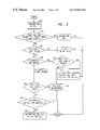
- FIG. 3 is a simplified flowchart illustration of a preferred method of managing network congestion at buffer 20 of FIGS. 1 and 2 in accordance with a preferred embodiment of the present invention
- FIG. 4 is a simplified block diagram of another preferred implementation of buffer 20 of FIG. 1 ;
- FIG. 5 is a simplified flowchart illustration of a preferred method of managing network congestion at buffer 20 of FIGS. 1 and 4 in accordance with a preferred embodiment of the present invention.
- FIGS. 6A and 6B taken together, are simplified flowchart illustrations of a preferred method of managing network congestion at buffer 20 of FIGS. 1 and 2 in accordance with another preferred embodiment of the present invention.
- FIG. 1 is a simplified block diagram of a network, such as a cell-switching network supporting a packet-switching protocol, constructed and operative in accordance with a preferred embodiment of the present invention.
- a network switch 10 typically an ATM switch, is shown having one or more physical network connections 12 as is known.
- Switch 10 is preferably capable of receiving network transmissions including packet-switched traffic such as TCP packets 14 from one or more packet sources and providing cell-switched traffic such as ARM cells 16 over one or more logical network connections, herein referred to as virtual circuits, such as VC 1 and VC 2 , to one or more receivers, such as R 1 and R 2 .
- Switch 10 preferably comprises a processing and logic unit 18 for managing a buffer 20 which may be a single buffer or a buffer pool.
- Buffer 20 is typically shared by one or more virtual circuits, such as VC 1 and VC 2 . While a single switch 10 is shown, it is appreciated that multiple switches, routers, and servers supporting packet-switching and cell-switching protocols as described herein may be employed as is known in the art.
- FIG. 2 is a simplified block diagram of a preferred implementation of buffer 20 of FIG. 1 constructed and operative in accordance with a preferred embodiment of the present invention.
- Buffer 20 typically comprises a safe region 22 Ad and a BPD region 24 .
- a region as referred to herein typically refers to a memory area as is known.
- Buffer 18 may additionally comprise an EPD region 26 .
- a BPD threshold 28 is typically provided bounding the BPD and safe regions.
- an EPD threshold 30 is typically provided bounding the BPD and EPD regions. It is a particular feature of the invention that buffer thresholds may be fixed or set dynamically to provide optimal levels of throughput
- Buffer 20 is typically bounded by a lower memory address 32 and an upper memory address 34 as is known.
- FIG. 3 is a simplified flowchart illustration of a preferred method of managing network congestion at buffer 20 of FIGS. 1 and 2 constructed and operative in accordance with a preferred embodiment of the present invention. It is appreciated that the steps of the method of FIG. 3 and of other methods described herein need not necessarily be performed in a particular order, and that in fact, for reasons of implementation, a particular implementation of the method may be performed in a different order than another particular implementation.
- a rejection indicator herein referred to as “b” (for “balanced”), is typically maintained for all virtual circuits, such as VC 1 and VC 2 , and is used to indicate the packet rejection status for each virtual circuit.
- FIG. 4 is a simplified block diagram of another preferred implementation of buffer 20 of FIG. 1 .
- Buffer 20 is shown being allocated to buffers 40 and 42 which represent separate buffers for virtual circuits VC 3 and VC 4 respectively, although buffer 20 may be allocated among any number of virtual circuits.
- Each buffer 40 and 42 preferably has a current buffer allocation (CBA) indicating the number of buffers currently in use by VC 3 and VC 4 respectively, an upper threshold (UT) indicating when EPD should be activated for each virtual circuit, and a maximum buffer allocation (MBA) indicating the maximum number of buffers that may be allocated to each virtual circuit, shown as MBA 3 and MBA 4 respectively.
- CBA current buffer allocation
- UT upper threshold
- MCA maximum buffer allocation
- MBA 3 and MBA 4 may be adjusted to arrive at new maximum buffer allocations MBA 3 and MBA 4 such as in accordance with the method described hereinbelow with reference to FIG. 5 .
- FIG. 5 is a simplified flowchart illustration of a preferred method of managing network congestion at buffer 20 of FIGS. 1 and 4 in accordance with a preferred embodiment of the present invention.
- a rejection indicator “b” is typically maintained for all virtual circuits, such as VC 3 and VC 4 , and is used to indicate the packet rejection status for each virtual circuit.
- a cell is received for a virtual circuit VC x , typically as part of a TCP packet received at switch 10 (step 300 ). If the cell belongs to a corrupted packet or to a packet that is being dropped (step 310 ) then the cell is discarded (step 360 ).
- FIGS. 6A and 6B are simplified flowchart illustrations of a preferred method of managing network congestion at buffer 20 of FIGS. 1 and 2 constructed and operative in accordance with another preferred embodiment of the present invention.
- Steps 300 - 600 correspond almost identically to steps 100 15 - 200 of FIG. 3 except as is now noted.
- the rejection indicator ‘b’ is checked for virtual circuit VC x (step 610 ). If b does not equal 1, the cell is buffered (step 620 ).
- step 630 the counter for VC x is decremented by 1 (step 630 ). If the counter is greater than 0 (step 640 ) then the cell is buffered (step 620 ). If the counter equals 0, then b is set to 0 for VC x (step 650 ) and the cell is buffered (step 620 ).
Abstract
Description
-
- G. Armitage and K. Adams, “Packet Reassembly During Cell Loss”, IEEE Network Mag, Vol. 7 No. 5 September 1993, pp. 26-34;
- A. Romanow and S. Floyd, “Dynamics of TCP Traffic over ATM Networks”, IEEE Journal on Selected Areas in Communications, May 1995; and
- J. Turner, “Maintaining High Throughput During Overload in ATM Switches”, Proceedings of IEEE Infocom '96. San Francisco, March 1996.
Claims (26)
Applications Claiming Priority (2)
| Application Number | Priority Date | Filing Date | Title |
|---|---|---|---|
| IL12227197A IL122271A (en) | 1997-11-21 | 1997-11-21 | Apparatus and method for managing network congestion |
| PCT/IL1998/000569 WO1999027464A1 (en) | 1997-11-21 | 1998-11-20 | Apparatus and method for managing network congestion |
Publications (1)
| Publication Number | Publication Date |
|---|---|
| US6870810B1 true US6870810B1 (en) | 2005-03-22 |
Family
ID=11070880
Family Applications (1)
| Application Number | Title | Priority Date | Filing Date |
|---|---|---|---|
| US09/554,840 Expired - Lifetime US6870810B1 (en) | 1997-11-21 | 1998-11-20 | Apparatus and method for managing network congestion |
Country Status (10)
| Country | Link |
|---|---|
| US (1) | US6870810B1 (en) |
| EP (1) | EP1032889B1 (en) |
| KR (1) | KR100594532B1 (en) |
| AT (1) | ATE324631T1 (en) |
| AU (1) | AU1257299A (en) |
| CY (1) | CY1105457T1 (en) |
| DE (1) | DE69834343T2 (en) |
| ES (1) | ES2260854T3 (en) |
| IL (1) | IL122271A (en) |
| WO (1) | WO1999027464A1 (en) |
Cited By (2)
| Publication number | Priority date | Publication date | Assignee | Title |
|---|---|---|---|---|
| US20040111503A1 (en) * | 2002-12-06 | 2004-06-10 | Intel Corporation | Method, system, and article of manufacture for increasing network throughput |
| US11153174B2 (en) * | 2018-06-15 | 2021-10-19 | Home Box Office, Inc. | Data service overload detection and mitigation |
Families Citing this family (7)
| Publication number | Priority date | Publication date | Assignee | Title |
|---|---|---|---|---|
| JP2001197119A (en) * | 2000-01-13 | 2001-07-19 | Nec Corp | Server device, network system and receiving load control method therefor |
| US20020018474A1 (en) * | 2000-06-01 | 2002-02-14 | Seabridge Ltd. | Efficient packet transmission over ATM |
| EP1261183A1 (en) * | 2001-05-23 | 2002-11-27 | Telefonaktiebolaget L M Ericsson (Publ) | Method and system for processing a data unit |
| KR20030000161A (en) * | 2001-06-22 | 2003-01-06 | 최복남 | A system for transmitting of advertisement e-mail and method thereof |
| WO2004006619A1 (en) * | 2002-07-02 | 2004-01-15 | Siemens Aktiengesellschaft | Early packet discard method for asynchronous transmission packets of fixed length |
| US7707320B2 (en) | 2003-09-05 | 2010-04-27 | Qualcomm Incorporated | Communication buffer manager and method therefor |
| CN107566206B (en) * | 2017-08-04 | 2020-09-04 | 华为技术有限公司 | Flow measuring method, equipment and system |
Citations (10)
| Publication number | Priority date | Publication date | Assignee | Title |
|---|---|---|---|---|
| US5140584A (en) | 1989-03-01 | 1992-08-18 | Kabushiki Kaisha Toshiba | Packet communication system and method of controlling same |
| US5335222A (en) * | 1990-08-09 | 1994-08-02 | Fujitsu Limited | Traffic control system for asynchronous transfer mode exchange |
| US5390299A (en) | 1991-12-27 | 1995-02-14 | Digital Equipment Corporation | System for using three different methods to report buffer memory occupancy information regarding fullness-related and/or packet discard-related information |
| EP0744850A2 (en) | 1995-05-22 | 1996-11-27 | Fore Systems, Inc. | Digital network including early packet discard mechanism with adjustable threshold |
| WO1996039763A1 (en) | 1995-06-05 | 1996-12-12 | General Datacomm, Inc. | Atm network switch with congestion control |
| US5838677A (en) | 1995-04-18 | 1998-11-17 | Hitachi, Ltd. | Switching system having means for congestion control by monitoring packets in a shared buffer and by suppressing the reading of packets from input buffers |
| US5914936A (en) * | 1996-05-16 | 1999-06-22 | Hitachi, Ltd. | ATM exchange performing traffic flow control |
| US6034945A (en) * | 1996-05-15 | 2000-03-07 | Cisco Technology, Inc. | Method and apparatus for per traffic flow buffer management |
| US6167027A (en) * | 1997-09-09 | 2000-12-26 | Cisco Technology, Inc. | Flow control technique for X.25 traffic in a high speed packet switching network |
| US6229789B1 (en) * | 1996-08-30 | 2001-05-08 | Sgs-Thomson Microelectronics Limited | Congestion avoidance in an ATM switch |
-
1997
- 1997-11-21 IL IL12227197A patent/IL122271A/en not_active IP Right Cessation
-
1998
- 1998-11-20 AU AU12572/99A patent/AU1257299A/en not_active Abandoned
- 1998-11-20 DE DE69834343T patent/DE69834343T2/en not_active Expired - Lifetime
- 1998-11-20 EP EP98955886A patent/EP1032889B1/en not_active Expired - Lifetime
- 1998-11-20 AT AT98955886T patent/ATE324631T1/en not_active IP Right Cessation
- 1998-11-20 US US09/554,840 patent/US6870810B1/en not_active Expired - Lifetime
- 1998-11-20 KR KR1020007005539A patent/KR100594532B1/en not_active IP Right Cessation
- 1998-11-20 ES ES98955886T patent/ES2260854T3/en not_active Expired - Lifetime
- 1998-11-20 WO PCT/IL1998/000569 patent/WO1999027464A1/en active IP Right Grant
-
2006
- 2006-07-20 CY CY20061101005T patent/CY1105457T1/en unknown
Patent Citations (10)
| Publication number | Priority date | Publication date | Assignee | Title |
|---|---|---|---|---|
| US5140584A (en) | 1989-03-01 | 1992-08-18 | Kabushiki Kaisha Toshiba | Packet communication system and method of controlling same |
| US5335222A (en) * | 1990-08-09 | 1994-08-02 | Fujitsu Limited | Traffic control system for asynchronous transfer mode exchange |
| US5390299A (en) | 1991-12-27 | 1995-02-14 | Digital Equipment Corporation | System for using three different methods to report buffer memory occupancy information regarding fullness-related and/or packet discard-related information |
| US5838677A (en) | 1995-04-18 | 1998-11-17 | Hitachi, Ltd. | Switching system having means for congestion control by monitoring packets in a shared buffer and by suppressing the reading of packets from input buffers |
| EP0744850A2 (en) | 1995-05-22 | 1996-11-27 | Fore Systems, Inc. | Digital network including early packet discard mechanism with adjustable threshold |
| WO1996039763A1 (en) | 1995-06-05 | 1996-12-12 | General Datacomm, Inc. | Atm network switch with congestion control |
| US6034945A (en) * | 1996-05-15 | 2000-03-07 | Cisco Technology, Inc. | Method and apparatus for per traffic flow buffer management |
| US5914936A (en) * | 1996-05-16 | 1999-06-22 | Hitachi, Ltd. | ATM exchange performing traffic flow control |
| US6229789B1 (en) * | 1996-08-30 | 2001-05-08 | Sgs-Thomson Microelectronics Limited | Congestion avoidance in an ATM switch |
| US6167027A (en) * | 1997-09-09 | 2000-12-26 | Cisco Technology, Inc. | Flow control technique for X.25 traffic in a high speed packet switching network |
Non-Patent Citations (5)
| Title |
|---|
| Armitage et al., "Packet Reassembly During Cell Loss," IEEE NETWORK, Sep. 1993, pp. 26-34. |
| http://whatis.com/atm.htm printout, "ATM", printed Sep. 21, 1997. |
| http://whatis.com/atm.htm printout, "packet", Sep. 21, 1997. |
| Romanow et al., "Dynamics of TCP Traffic Over ATM Networks," IEEE, 1995, PP. 633-641. |
| Turner, J., "Maintaining High Throughput During Overload in ATM Switches," IEEE, 1996, pp. 287-295. |
Cited By (4)
| Publication number | Priority date | Publication date | Assignee | Title |
|---|---|---|---|---|
| US20040111503A1 (en) * | 2002-12-06 | 2004-06-10 | Intel Corporation | Method, system, and article of manufacture for increasing network throughput |
| US7373419B2 (en) * | 2002-12-06 | 2008-05-13 | Intel Corporation | Method, system, and article of manufacture for increasing network throughput |
| US11153174B2 (en) * | 2018-06-15 | 2021-10-19 | Home Box Office, Inc. | Data service overload detection and mitigation |
| US11606261B2 (en) | 2018-06-15 | 2023-03-14 | Home Box Office, Inc. | Data service overload detection and mitigation |
Also Published As
| Publication number | Publication date |
|---|---|
| KR20010024661A (en) | 2001-03-26 |
| DE69834343D1 (en) | 2006-06-01 |
| EP1032889B1 (en) | 2006-04-26 |
| CY1105457T1 (en) | 2010-04-28 |
| ES2260854T3 (en) | 2006-11-01 |
| IL122271A (en) | 2001-01-11 |
| EP1032889A4 (en) | 2005-05-04 |
| KR100594532B1 (en) | 2006-06-30 |
| IL122271A0 (en) | 1998-04-05 |
| DE69834343T2 (en) | 2007-01-04 |
| ATE324631T1 (en) | 2006-05-15 |
| AU1257299A (en) | 1999-06-15 |
| WO1999027464A1 (en) | 1999-06-03 |
| EP1032889A1 (en) | 2000-09-06 |
Similar Documents
| Publication | Publication Date | Title |
|---|---|---|
| US5666353A (en) | Frame based traffic policing for a digital switch | |
| KR100949245B1 (en) | Congestion notification in 3g radio access | |
| US6535482B1 (en) | Congestion notification from router | |
| US6625118B1 (en) | Receiver based congestion control | |
| US7145868B2 (en) | Congestion management in a multi-port shared memory switch | |
| US6388992B2 (en) | Flow control technique for traffic in a high speed packet switching network | |
| US6560198B1 (en) | Method and system for stabilized random early detection using packet sampling | |
| US6862621B2 (en) | Flow controlling apparatus and node apparatus | |
| US6697331B1 (en) | Link layer acknowledgement and retransmission for cellular telecommunications | |
| Keshav et al. | SMART retransmission: Performance with overload and random losses | |
| US20070127392A1 (en) | Delay-based overflow routing in communication systems | |
| US6870810B1 (en) | Apparatus and method for managing network congestion | |
| JPH088926A (en) | Buffer priority control system | |
| Bestavros et al. | TCP Boston: a fragmentation-tolerant TCP protocol for ATM networks | |
| US7218608B1 (en) | Random early detection algorithm using an indicator bit to detect congestion in a computer network | |
| KR20030054545A (en) | Method of Controlling TCP Congestion | |
| US6434116B1 (en) | Method and system for stabilized random early detection using connection sampling | |
| WO2004084508A1 (en) | Method and apparatus for controlling congestion in communications network | |
| Cohen et al. | Balanced packet discard for improving TCP performance in ATM networks | |
| Sisalem et al. | Binary congestion notification in TCP | |
| Tokuda et al. | Analysis and Improvement of the Fairness between Long-lived and Short-lived TCP Connections | |
| JPH11355283A (en) | Packet abandonment control method and node for realizing the method | |
| Platt et al. | Some aspects of traffic management in frame relay networks | |
| JP2000341274A (en) | Method for controlling cell discarding in atm switching device | |
| Aarstad et al. | Experiments on TCP over UBR Performance in the EXPERT Testbed |
Legal Events
| Date | Code | Title | Description |
|---|---|---|---|
| AS | Assignment |
Owner name: ECI TELECOM LTD., ISRAEL Free format text: ASSIGNMENT OF ASSIGNORS INTEREST;ASSIGNOR:COHEN, REUVEN;REEL/FRAME:011900/0707 Effective date: 20000501 |
|
| STCF | Information on status: patent grant |
Free format text: PATENTED CASE |
|
| FEPP | Fee payment procedure |
Free format text: PAYOR NUMBER ASSIGNED (ORIGINAL EVENT CODE: ASPN); ENTITY STATUS OF PATENT OWNER: LARGE ENTITY |
|
| AS | Assignment |
Owner name: CREDIT SUISSE, AS COLLATERAL AGENT, NEW YORK Free format text: SECURITY AGREEMENT;ASSIGNORS:EPSILON 1 LTD;ECI TELECOM LTD;LIGHTSCAPE NETWORKS LTD.;AND OTHERS;REEL/FRAME:020431/0705 Effective date: 20071214 |
|
| AS | Assignment |
Owner name: CREDIT SUISSE, CAYMAN ISLANDS BRANCH, AS COLLATERA Free format text: SECURITY AGREEMENT;ASSIGNORS:EPSILON 1 LTD.;ECI TELECOM LTD.;LIGHTSCAPE NETWORKS LTD.;AND OTHERS;REEL/FRAME:020442/0874 Effective date: 20071214 |
|
| FPAY | Fee payment |
Year of fee payment: 4 |
|
| FPAY | Fee payment |
Year of fee payment: 8 |
|
| AS | Assignment |
Owner name: CREDIT SUISSE AG, CAYMAN ISLANDS BRANCH, AS COLLAT Free format text: SECURITY AGREEMENT;ASSIGNORS:ECI TELECOM INC.;ECI TELECOM LTD.;EPSILON 1 LTD.;AND OTHERS;REEL/FRAME:033719/0084 Effective date: 20140813 Owner name: CREDIT SUISSE AG, CAYMAN ISLANDS BRANCH, AS COLLAT Free format text: ASSIGNMENT OF ASSIGNORS INTEREST;ASSIGNORS:ECI TELECOM INC.;ECI TELECOM LTD.;EPSILON 1 LTD.;AND OTHERS;REEL/FRAME:033719/0084 Effective date: 20140813 |
|
| FPAY | Fee payment |
Year of fee payment: 12 |
|
| AS | Assignment |
Owner name: TELECOM INVESTMENTS (FINANCE) LLC, DELAWARE Free format text: RELEASE BY SECURED PARTY;ASSIGNOR:CREDIT SUISSE AG, CAYMAN ISLANDS BRANCH, AS COLLATERAL AGENT;REEL/FRAME:045942/0140 Effective date: 20180329 Owner name: ECI HOLDING (HUNGARY) KORLATOLT FELELOSSEGU TARSAS Free format text: RELEASE BY SECURED PARTY;ASSIGNOR:CREDIT SUISSE AG, CAYMAN ISLANDS BRANCH, AS COLLATERAL AGENT;REEL/FRAME:045942/0140 Effective date: 20180329 Owner name: ECI TELECOM INC., FLORIDA Free format text: RELEASE BY SECURED PARTY;ASSIGNOR:CREDIT SUISSE AG, CAYMAN ISLANDS BRANCH, AS COLLATERAL AGENT;REEL/FRAME:045942/0140 Effective date: 20180329 Owner name: EPSILON 1 LTD., ISRAEL Free format text: RELEASE BY SECURED PARTY;ASSIGNOR:CREDIT SUISSE AG, CAYMAN ISLANDS BRANCH, AS COLLATERAL AGENT;REEL/FRAME:045942/0140 Effective date: 20180329 Owner name: ECI TELECOM LTD., ISRAEL Free format text: RELEASE BY SECURED PARTY;ASSIGNOR:CREDIT SUISSE AG, CAYMAN ISLANDS BRANCH, AS COLLATERAL AGENT;REEL/FRAME:045942/0140 Effective date: 20180329 Owner name: ECI TELECOM (UK) LIMITED, UNITED KINGDOM Free format text: RELEASE BY SECURED PARTY;ASSIGNOR:CREDIT SUISSE AG, CAYMAN ISLANDS BRANCH, AS COLLATERAL AGENT;REEL/FRAME:045942/0140 Effective date: 20180329 |