US6843967B2 - Curing unit - Google Patents
Curing unit Download PDFInfo
- Publication number
- US6843967B2 US6843967B2 US10/411,426 US41142603A US6843967B2 US 6843967 B2 US6843967 B2 US 6843967B2 US 41142603 A US41142603 A US 41142603A US 6843967 B2 US6843967 B2 US 6843967B2
- Authority
- US
- United States
- Prior art keywords
- leds
- cover
- curing
- light
- light source
- Prior art date
- Legal status (The legal status is an assumption and is not a legal conclusion. Google has not performed a legal analysis and makes no representation as to the accuracy of the status listed.)
- Expired - Fee Related, expires
Links
- 239000005548 dental material Substances 0.000 claims abstract description 19
- 239000011248 coating agent Substances 0.000 claims description 3
- 238000000576 coating method Methods 0.000 claims description 3
- 238000006116 polymerization reaction Methods 0.000 abstract description 8
- 239000012260 resinous material Substances 0.000 abstract description 4
- 238000010926 purge Methods 0.000 abstract description 3
- 239000000463 material Substances 0.000 description 10
- 239000002131 composite material Substances 0.000 description 3
- 229910052736 halogen Inorganic materials 0.000 description 2
- 150000002367 halogens Chemical class 0.000 description 2
- 238000012986 modification Methods 0.000 description 2
- 230000004048 modification Effects 0.000 description 2
- 239000000126 substance Substances 0.000 description 2
- 239000000758 substrate Substances 0.000 description 2
- GDOPTJXRTPNYNR-UHFFFAOYSA-N CC1CCCC1 Chemical compound CC1CCCC1 GDOPTJXRTPNYNR-UHFFFAOYSA-N 0.000 description 1
- 241000251730 Chondrichthyes Species 0.000 description 1
- 150000001252 acrylic acid derivatives Chemical class 0.000 description 1
- 230000003213 activating effect Effects 0.000 description 1
- 239000012190 activator Substances 0.000 description 1
- 230000009286 beneficial effect Effects 0.000 description 1
- 238000001816 cooling Methods 0.000 description 1
- 230000007812 deficiency Effects 0.000 description 1
- 239000011350 dental composite resin Substances 0.000 description 1
- 238000010586 diagram Methods 0.000 description 1
- 230000008030 elimination Effects 0.000 description 1
- 238000003379 elimination reaction Methods 0.000 description 1
- 239000012530 fluid Substances 0.000 description 1
- 239000003999 initiator Substances 0.000 description 1
- QSHDDOUJBYECFT-UHFFFAOYSA-N mercury Chemical compound [Hg] QSHDDOUJBYECFT-UHFFFAOYSA-N 0.000 description 1
- 150000002734 metacrylic acid derivatives Chemical class 0.000 description 1
- 229910001507 metal halide Inorganic materials 0.000 description 1
- 150000005309 metal halides Chemical class 0.000 description 1
- 238000000034 method Methods 0.000 description 1
- 229920003023 plastic Polymers 0.000 description 1
- 230000001681 protective effect Effects 0.000 description 1
- 239000011347 resin Substances 0.000 description 1
- 229920005989 resin Polymers 0.000 description 1
- 239000004065 semiconductor Substances 0.000 description 1
- 239000007787 solid Substances 0.000 description 1
- 239000002904 solvent Substances 0.000 description 1
- 230000003595 spectral effect Effects 0.000 description 1
- WFKWXMTUELFFGS-UHFFFAOYSA-N tungsten Chemical compound [W] WFKWXMTUELFFGS-UHFFFAOYSA-N 0.000 description 1
- 229910052721 tungsten Inorganic materials 0.000 description 1
- 239000010937 tungsten Substances 0.000 description 1
- 125000000391 vinyl group Chemical group [H]C([*])=C([H])[H] 0.000 description 1
- 229910052724 xenon Inorganic materials 0.000 description 1
- FHNFHKCVQCLJFQ-UHFFFAOYSA-N xenon atom Chemical compound [Xe] FHNFHKCVQCLJFQ-UHFFFAOYSA-N 0.000 description 1
Images


Classifications
-
- A—HUMAN NECESSITIES
- A61—MEDICAL OR VETERINARY SCIENCE; HYGIENE
- A61C—DENTISTRY; APPARATUS OR METHODS FOR ORAL OR DENTAL HYGIENE
- A61C19/00—Dental auxiliary appliances
- A61C19/003—Apparatus for curing resins by radiation
Definitions
- the present invention relates generally to light for a curing unit and more specifically to light for use in a curing unit for dental materials.
- Curing is the processing of a plastic or resinous material from a fluid or soft and compliant state to a permanent hard, durable and solid state. Conventionally, this is accomplished both by the elimination of solvents and by chemical changes involving interlinking of molecules commonly known as polymerization of the material. Of the two, polymerization is the more advantageous since it does not commonly involve dimensional changes and usually produces a substantial increase in the strength of the material. Polymerization is usually caused by the addition of activating chemicals (activators), by irradiation with some form of wave energy, either electric or electromagnetic in nature, or by applying heat, or by a combination thereof.
- activators activating chemicals
- incandescent lamps such as halogen lamps as light sources for a laboratory curing apparatus generate excessive unwanted heat and also have a short life span, typically 50 hours.
- the heat may melt the pressure vessel or heat the composite material above recommended temperatures.
- the incandescent lights are very power inefficient since most of the light is not needed and is the wrong wavelength for the photo-initiators used in the dental composite material. Components to remove the unwanted heat are usually necessary adding to the cost of the device.
- the curing apparatus of the present invention wherein rapid curing is provided by using light, pressure, pressure and light, or purge, pressure and light to cure resinous materials by application of energy from an external source to excite polymerization in a polymerizable system.
- a curing chamber is provided to house the polymerizable dental material.
- the apparatus utilizes light emitting diodes (LEDs) to radiate energy to polymerize the dental materials.
- the LEDs are positioned optimally within the curing apparatus to provide efficient, effective polymerization of the dental materials.
- FIG. 1 is perspective view of a curing apparatus of the present invention
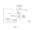
- FIG. 2 is a block diagram showing the electrical connections and air line connections of the apparatus of FIG. 1 ;
- FIG. 3 a perspective view of the apparatus of FIG. 1 showing the internal components
- FIG. 4 is perspective view of a curing chamber having LEDs positioned in the floor of the chamber
- FIG. 5 is a perspective view of an alternate embodiment of a curing chamber having LEDs positioned on the dome cover;
- FIG. 6 is a perspective view of an alternate embodiment of a curing chamber having LEDs positioned on the dome cover;
- FIG. 7 is a perspective view of an alternate embodiment of a curing chamber having LEDs positioned along the perimeter of the dome cover.
- FIG. 8 is a perspective view of an alternate embodiment of a curing chamber having LEDs rotating about the curing dome.
- the present invention provides a new and improved curing apparatus for curing a polymerizable resinous material, such as a dental material.
- a polymerizable resinous material such as a dental material.
- U.S. Pat. Nos. 4,873,446, 4,839,521, 5,040,964, and 4,309,617 are directed to polymerization and/or curing of materials and are hereby incorporated by reference.
- the dental material may include, but is not limited to at least one filled or unfilled resin having at least one ethylenically unsaturated group. Examples of the ethylenically unsaturated groups include acrylates, methacrylates, vinyl groups and combinations thereof.
- FIGS. 1 and 3 show a curing apparatus 10 for curing dental materials in a variety of modes including light alone, pressure alone (does not cure, but can be used to reduce porosity), light and pressure in combination, and a purge cycle to be used with light and pressure.
- Curing apparatus 10 provides a facile method of curing by providing a curing chamber, which is preferably an air-tight chamber, 20 , shown in FIG. 4 .
- the curing chamber includes a cover 22 , which is preferably dome-shaped and is located in a cover or top section 32 of the curing apparatus, and a base 24 which is part of the base or bottom section 38 of the curing apparatus.
- a work piece 25 may be placed on base 24 of bottom section 38 when a curing operation is to be performed.
- FIG. 2 is provided to show the electrical connections and air or gas line layout.
- the front panel 40 is the control panel that is operatively associated with a processing device located internally.
- the control panel receives input from an operator relating to the light source and the gas source.
- the processing device is operatively associated with the light source and the gas source for controlling curing of the dental material by light and pressure within the air-tight chamber.
- the processing device may include, but is not limited to, a microprocessor, a microcontroller, a microcomputer, a controller, a digital signal processor, a central processing unit (CPU), or an application specific integrated circuit (ASIC).
- the processing device may be configured to cause gas to supply gas under pressure to the air-tight chamber prior to the time the light source supplies light to the chamber.
- the processing device may be configured to cause the gas pressure to be initially supplied and subsequently released at least twice in succession, followed by application of pressure, whereby gas pressure is maintained at a constant level with in the chamber during the time the light source supplies light to the chamber.
- FIG. 3 shows a light source comprising two lamps 39 arranged above cover 22 , which cover may be transparent, positioned over base 24 of bottom section 38 , which can create air-tight chamber 20 when in closed position.
- the lamps may comprise light emitting diodes, tungsten, halogen, mercury vapor, short arc xenon, or a metal halide source.
- the light source may comprise one or a plurality of lamps directed at base 24 .
- the spectral output of the lamp utilized herein is in the range of between about 380 nm to about 550 nm.
- the lamps comprise light emitting diodes.
- the LEDs may be positioned in a variety of ways to provide optimal curing of dental components
- FIG. 4 shows the LEDs 26 positioned on base 24 .
- Polymerizable material 25 is placed on base 24 and dome cover 22 is positioned thereon.
- LEDs 26 located on base 24 may be covered by a protective transparent cover 28 to prevent any seepage of polymeric material onto the LEDs.
- LEDs 26 are optimally located on base 24 to provide direct application of light to the polymerizable material.
- Dome cover 22 may be transparent or opaque and may be covered with a reflective coating on the internal side to reflect any upwardly emitted light, down toward the polymerizable material.
- Base 24 acts as a heat sink for the power created by the LED semiconductor junction, reducing the need for cooling aids, such as fans.
- FIG. 5 shows a dome cover 50 with LEDs 52 mounted in cover 24 so that light is transmitted directly from the LEDs to the material being cured.
- LEDs may be mounted in a continuous pattern over the surface of cover 50 .
- the LEDs may be mounted continuously as shown or in a variety of different patterns, as desired.
- FIG. 6 shows an alternate embodiment of a dome cover 50 having LEDS 62 mounted to cover 64 in a series of locations on the surface of cover 34 .
- the LEDs 62 are shown mounted on a substrate 66 and substrates 66 may be mounted continuously along the lower surface as shown or in a variety of different patterns, as desired.
- covers 50 and 64 may include a reflective internal surface on the areas where the LEDS are not located to provide reflectance of light to the material being cured.
- FIG. 7 shows dome cover 70 having LEDs 72 mounted along the perimeter of cover 70 , so that light is transmitted through cover 70 .
- LEDs 72 may be connected to cover 70 or may be independently located proximate cover 70 .
- Cover 70 may be completely transparent or transparent only in those locations where the light is directed.
- FIG. 8 shows yet another embodiment of dome cover 80 having LEDs 82 located above cover 80 and rotatable around cover 80 to provide even and continuous light to the dental material being cured.
- the wavelength of the LEDs used herein are in the wavelength range from about 380 to about 550 nanometers.
- Commercially available LEDs useful herein include Luxeon Star Power Light Source LEDs from Lumileds in San Jose, Calif. and Shark High Flux LED Illuminators from Opto Technology Inc. in Wheeling, Ill.
- the dome described herein in combination with the LEDs is used in a light curing apparatus or in a light and pressure curing apparatus.
- the dome is preferably used in a light curing apparatus or in a light and pressure curing apparatus such as that described in copending application Ser. No. 10/120,934, filed Apr. 11, 2002 entitled Curing Unit For Dental Materials, naming one common inventor, and is hereby incorporated by reference.
Abstract
Description
Claims (24)
Priority Applications (1)
| Application Number | Priority Date | Filing Date | Title |
|---|---|---|---|
| US10/411,426 US6843967B2 (en) | 2002-04-11 | 2003-04-10 | Curing unit |
Applications Claiming Priority (2)
| Application Number | Priority Date | Filing Date | Title |
|---|---|---|---|
| US37188102P | 2002-04-11 | 2002-04-11 | |
| US10/411,426 US6843967B2 (en) | 2002-04-11 | 2003-04-10 | Curing unit |
Publications (2)
| Publication Number | Publication Date |
|---|---|
| US20030228243A1 US20030228243A1 (en) | 2003-12-11 |
| US6843967B2 true US6843967B2 (en) | 2005-01-18 |
Family
ID=29715202
Family Applications (1)
| Application Number | Title | Priority Date | Filing Date |
|---|---|---|---|
| US10/411,426 Expired - Fee Related US6843967B2 (en) | 2002-04-11 | 2003-04-10 | Curing unit |
Country Status (1)
| Country | Link |
|---|---|
| US (1) | US6843967B2 (en) |
Cited By (7)
| Publication number | Priority date | Publication date | Assignee | Title |
|---|---|---|---|---|
| US20030193119A1 (en) * | 2002-04-11 | 2003-10-16 | George Zychek | Curing unit for dental materials |
| US20050205882A1 (en) * | 2004-03-16 | 2005-09-22 | John Condon | LED-photo-curing device |
| US20060013014A1 (en) * | 2004-07-02 | 2006-01-19 | Robert Hayman | Dental light devices having an improved heat sink |
| US20080038306A1 (en) * | 2006-03-13 | 2008-02-14 | David Nathaniel E | Fluidic Tissue Augmentation Compositions and Methods |
| US20080101073A1 (en) * | 2006-11-01 | 2008-05-01 | Discus Dental, Llc | Dental Light Devices Having an Improved Heat Sink |
| US20090259166A1 (en) * | 2008-04-10 | 2009-10-15 | Kythera Biopharmaceuticals, Inc. | Systems and Methods for Transdermal Photo-Polymerization |
| US20110129790A1 (en) * | 2008-08-06 | 2011-06-02 | Naym 55 Dental Technologies Ltd. | Dental restoration conditioning apparatus and method |
Families Citing this family (1)
| Publication number | Priority date | Publication date | Assignee | Title |
|---|---|---|---|---|
| EP3842009B1 (en) | 2018-08-24 | 2022-12-28 | Tokuyama Dental Corporation | Polymerization apparatus |
Citations (5)
| Publication number | Priority date | Publication date | Assignee | Title |
|---|---|---|---|---|
| US6077073A (en) * | 1998-09-15 | 2000-06-20 | Jacob; Gregory S. | Light emitting diode-array light apparatus |
| US20010046652A1 (en) | 2000-03-08 | 2001-11-29 | Ostler Scientific Internationsl, Inc. | Light emitting diode light source for curing dental composites |
| US6386865B1 (en) * | 1997-02-14 | 2002-05-14 | Bisco Inc. | System for fabrication of indirect dental restoratives |
| US20020172918A1 (en) | 2001-05-23 | 2002-11-21 | Ivoclar Vivadent Ag | Light hardening apparatus for effecting the light hardening of dental restoration pieces |
| US20020177098A1 (en) | 2001-05-23 | 2002-11-28 | Ivoclar Vivadent Ag | Light hardening apparatus particularly for a dental practice |
-
2003
- 2003-04-10 US US10/411,426 patent/US6843967B2/en not_active Expired - Fee Related
Patent Citations (5)
| Publication number | Priority date | Publication date | Assignee | Title |
|---|---|---|---|---|
| US6386865B1 (en) * | 1997-02-14 | 2002-05-14 | Bisco Inc. | System for fabrication of indirect dental restoratives |
| US6077073A (en) * | 1998-09-15 | 2000-06-20 | Jacob; Gregory S. | Light emitting diode-array light apparatus |
| US20010046652A1 (en) | 2000-03-08 | 2001-11-29 | Ostler Scientific Internationsl, Inc. | Light emitting diode light source for curing dental composites |
| US20020172918A1 (en) | 2001-05-23 | 2002-11-21 | Ivoclar Vivadent Ag | Light hardening apparatus for effecting the light hardening of dental restoration pieces |
| US20020177098A1 (en) | 2001-05-23 | 2002-11-28 | Ivoclar Vivadent Ag | Light hardening apparatus particularly for a dental practice |
Cited By (11)
| Publication number | Priority date | Publication date | Assignee | Title |
|---|---|---|---|---|
| US20030193119A1 (en) * | 2002-04-11 | 2003-10-16 | George Zychek | Curing unit for dental materials |
| US7186108B2 (en) | 2002-04-11 | 2007-03-06 | Pentron Laboratory Technologies, Llc | Curing unit for dental materials |
| US20050205882A1 (en) * | 2004-03-16 | 2005-09-22 | John Condon | LED-photo-curing device |
| US20060013014A1 (en) * | 2004-07-02 | 2006-01-19 | Robert Hayman | Dental light devices having an improved heat sink |
| US7581846B2 (en) | 2004-07-02 | 2009-09-01 | Discus Dental, Llc | Dental light devices having an improved heat sink |
| US20080038306A1 (en) * | 2006-03-13 | 2008-02-14 | David Nathaniel E | Fluidic Tissue Augmentation Compositions and Methods |
| US20110087152A1 (en) * | 2006-03-13 | 2011-04-14 | David Nathaniel E | Fluidic tissue augmentation compositions and methods |
| US20080101073A1 (en) * | 2006-11-01 | 2008-05-01 | Discus Dental, Llc | Dental Light Devices Having an Improved Heat Sink |
| US20090259166A1 (en) * | 2008-04-10 | 2009-10-15 | Kythera Biopharmaceuticals, Inc. | Systems and Methods for Transdermal Photo-Polymerization |
| US20110129790A1 (en) * | 2008-08-06 | 2011-06-02 | Naym 55 Dental Technologies Ltd. | Dental restoration conditioning apparatus and method |
| US8828286B2 (en) * | 2008-08-06 | 2014-09-09 | Naym 55 Dental Technologies Ltd. | Dental restoration conditioning apparatus and method |
Also Published As
| Publication number | Publication date |
|---|---|
| US20030228243A1 (en) | 2003-12-11 |
Similar Documents
| Publication | Publication Date | Title |
|---|---|---|
| US8696155B2 (en) | Solid-state light sources for curing and surface modification | |
| JP4653712B2 (en) | UV light emitting diode device | |
| WO2004011848A3 (en) | Method and apparatus for using light emitting diodes for curing | |
| JP5259729B2 (en) | LED-based lighting fixtures for large building lighting | |
| US6843967B2 (en) | Curing unit | |
| US20080268401A1 (en) | Led Having Wide Wavelength-Range and Light Curing Unit Using the Same | |
| JP2011098073A (en) | Nail coat gel drying machine | |
| RU2759656C1 (en) | Polymerization device | |
| US10183481B2 (en) | Energy efficient multi-spectrum screen exposure system | |
| CN1597087A (en) | Ultraviolet irradiating device | |
| JP2012034891A (en) | Photopolymerization device | |
| JP2000156525A (en) | Thin and uniform lighting device using a plurality of leds | |
| JP2002360614A (en) | Dental light device | |
| JP2011189312A (en) | Light irradiation device and light exposure method | |
| JP2001121552A (en) | Moving type ultraviolet curing apparatus | |
| JP2003033374A (en) | Photopolymerization device for working | |
| JP7127698B2 (en) | electrical equipment | |
| JP2005161002A (en) | Light emitting diode photopolymerization apparatus with heating function | |
| CN216297003U (en) | Automatic induction type photocuring equipment | |
| KR200286884Y1 (en) | Muti-Light Curing Apparatus | |
| JP7233033B2 (en) | lighting equipment | |
| JP2003061983A (en) | Lighting system | |
| JP7316602B2 (en) | lighting equipment | |
| JP6661093B2 (en) | Polymerization equipment | |
| KR20180016868A (en) | Curing Device Using Infrared Ray LED |
Legal Events
| Date | Code | Title | Description |
|---|---|---|---|
| AS | Assignment |
Owner name: PENTRON LABORATORY TECHNOLOGIES, LLC, CONNECTICUT Free format text: ASSIGNMENT OF ASSIGNORS INTEREST;ASSIGNOR:CLARK, DANIEL P.;REEL/FRAME:014226/0483 Effective date: 20030620 |
|
| AS | Assignment |
Owner name: COHEN, GORDON S., CONNECTICUT Free format text: SECURITY AGREEMENT;ASSIGNOR:PENTRON LABORATORY TECHNOLOGIES, LLC;REEL/FRAME:015748/0743 Effective date: 20050309 Owner name: THE COHEN FAMILY TRUST PARTNERSHIP, CONNECTICUT Free format text: SECURITY AGREEMENT;ASSIGNOR:PENTRON LABORATORY TECHNOLOGIES, LLC;REEL/FRAME:015748/0743 Effective date: 20050309 |
|
| AS | Assignment |
Owner name: COHEN, GORDON S., CONNECTICUT Free format text: AMENDMENT TO MORTGAGE AND SECURITY AGREEMENT RECORDED AT REEL 015748 AND FRAME 0743 ON MARCH 9, 2005;ASSIGNOR:PENTRON LABORATORY TECHNOLOGIES, LLC;REEL/FRAME:018323/0240 Effective date: 20060724 Owner name: THE COHEN FAMILY TRUST PARTNERSHIP, CONNECTICUT Free format text: AMENDMENT TO MORTGAGE AND SECURITY AGREEMENT RECORDED AT REEL 015748 AND FRAME 0743 ON MARCH 9, 2005;ASSIGNOR:PENTRON LABORATORY TECHNOLOGIES, LLC;REEL/FRAME:018323/0240 Effective date: 20060724 |
|
| AS | Assignment |
Owner name: THE COHEN FAMILY TRUST PARTNERSHIP, CONNECTICUT Free format text: AMENDMENT NO. 3 TO MORTGAGE AND SECURITY AGREEMENT DATED MARCH 9, 2005, AMENDED JULY 24, 2006 AND SECOND AMENDMENT DATED JUNE 15, 2007;ASSIGNOR:PENTRON LABORATORY TECHNOLOGIES, LLC;REEL/FRAME:020174/0885 Effective date: 20070925 Owner name: COHEN, GORDON S., CONNECTICUT Free format text: AMENDMENT NO. 2 TO MORTGAGE AND SECURITY AGREEMENT DATED MARCH 9, 2005 AND AMENDED JULY 24, 2006;ASSIGNOR:PENTRON LABORATORY TECHNOLOGIES, LLC;REEL/FRAME:020174/0742 Effective date: 20070615 Owner name: COHEN, GORDON S., CONNECTICUT Free format text: AMENDMENT NO. 3 TO MORTGAGE AND SECURITY AGREEMENT DATED MARCH 9, 2005, AMENDED JULY 24, 2006 AND SECOND AMENDMENT DATED JUNE 15, 2007;ASSIGNOR:PENTRON LABORATORY TECHNOLOGIES, LLC;REEL/FRAME:020174/0885 Effective date: 20070925 Owner name: THE COHEN FAMILY TRUST PARTNERSHIP, CONNECTICUT Free format text: AMENDMENT NO. 2 TO MORTGAGE AND SECURITY AGREEMENT DATED MARCH 9, 2005 AND AMENDED JULY 24, 2006;ASSIGNOR:PENTRON LABORATORY TECHNOLOGIES, LLC;REEL/FRAME:020174/0742 Effective date: 20070615 |
|
| REMI | Maintenance fee reminder mailed | ||
| FPAY | Fee payment |
Year of fee payment: 4 |
|
| SULP | Surcharge for late payment | ||
| AS | Assignment |
Owner name: PENTRON LABORATORY TECHNOLOGIES, LLC, CONNECTICUT Free format text: RELEASE BY SECURED PARTY;ASSIGNORS:COHEN, GORDON S.;THE COHEN FAMILY TRUST PARTNERSHIP;REEL/FRAME:021380/0295 Effective date: 20080801 |
|
| FEPP | Fee payment procedure |
Free format text: PAT HOLDER NO LONGER CLAIMS SMALL ENTITY STATUS, ENTITY STATUS SET TO UNDISCOUNTED (ORIGINAL EVENT CODE: STOL); ENTITY STATUS OF PATENT OWNER: LARGE ENTITY |
|
| SULP | Surcharge for late payment | ||
| REMI | Maintenance fee reminder mailed | ||
| LAPS | Lapse for failure to pay maintenance fees | ||
| STCH | Information on status: patent discontinuation |
Free format text: PATENT EXPIRED DUE TO NONPAYMENT OF MAINTENANCE FEES UNDER 37 CFR 1.362 |
|
| FP | Lapsed due to failure to pay maintenance fee |
Effective date: 20130118 |