US6841974B2 - Battery charging method - Google Patents
Battery charging method Download PDFInfo
- Publication number
- US6841974B2 US6841974B2 US10/099,932 US9993202A US6841974B2 US 6841974 B2 US6841974 B2 US 6841974B2 US 9993202 A US9993202 A US 9993202A US 6841974 B2 US6841974 B2 US 6841974B2
- Authority
- US
- United States
- Prior art keywords
- voltage
- battery
- pulse
- charging
- approximately
- Prior art date
- Legal status (The legal status is an assumption and is not a legal conclusion. Google has not performed a legal analysis and makes no representation as to the accuracy of the status listed.)
- Expired - Fee Related, expires
Links
Images


Classifications
-
- H—ELECTRICITY
- H02—GENERATION; CONVERSION OR DISTRIBUTION OF ELECTRIC POWER
- H02J—CIRCUIT ARRANGEMENTS OR SYSTEMS FOR SUPPLYING OR DISTRIBUTING ELECTRIC POWER; SYSTEMS FOR STORING ELECTRIC ENERGY
- H02J7/00—Circuit arrangements for charging or depolarising batteries or for supplying loads from batteries
- H02J7/007—Regulation of charging or discharging current or voltage
- H02J7/00711—Regulation of charging or discharging current or voltage with introduction of pulses during the charging process
Definitions
- the invention relates to rechargeable batteries and, in particular, a battery charging system.
- Batteries are used to power a wide variety of electrical devices.
- the devices powered by batteries range from a simple flashlight to a complex portable computer.
- batteries power devices ranging from a small cellular phone to a relatively large vehicle.
- a battery is a power source comprising one or more electrochemical cells, also referred to as voltaic cells.
- Each voltaic cell comprises two electrodes called a cathode and an anode, with an electrolyte therebetween. Electrochemical reaction between the electrolyte and the electrode causes separation of positive and negative charges, wherein the positive charge accumulate on the anode and the negative charge accumulate on the cathode thereby forming a potential difference.
- an external path circuit
- the potential difference causes the charge to flow (electrical current) in the circuit thereby performing a variety of functions in an electrical device.
- the reaction replenishes the charge up to a point after which the chemical reaction can no longer be sustained.
- a battery with such “drained” voltaic cell(s) is either replaced or recharged in order to power the electrical device.
- Batteries can be grouped into two broad types—a primary type and a secondary type.
- the primary type comprises disposable batteries
- the secondary type comprises rechargeable batteries.
- the rechargeable batteries can further be grouped into four types: NiMH (nickel metal hydride), NiCd (nickel cadmium), LiIon (Lithium Ion), and SLA (Sealed Lead Acid) batteries. While the composition of the electrolyte and the electrodes vary among the four types of rechargeable batteries, basic working principle is essentially the same.
- the aforementioned charge-generating electrochemical reaction is reversible in a recharging (or simply referred to as charging) process.
- the charging process comprises introducing charge from an external source (charger) into the battery such that the charge drives the reverse electrochemical reaction inside the voltaic cell(s).
- charger an external source
- Pulse charging is known to be an advantageous method of charging in many aspects, including the fact that pulsing of charge followed by a rest period allows the input charge to be absorbed more efficiently.
- traditional pulse chargers further attempts to decrease the charging time by modulating the amplitude of the charge pulses as the charging progresses, based on battery indicators such as voltage.
- voltage of the battery being charged is one of the indicators of the state of battery's charge as well as how well the charge is being received by the battery.
- a quiescent voltage of the battery (open circuit terminal voltage) is roughly indicative of the charge state of a given battery, and the terminal voltage during a charge pulse relative to the quiescent voltage is indicative of the charge absorption rate.
- a traditional pulse charger may modulate the charge pulse amplitude based on the monitored voltages.
- Such a pulse charger has drawbacks, including the charger being rather battery specific.
- the battery specific nature of the conventional pulse chargers arises from the fact that charge pulse amplitude (current amplitude) is modulated based on voltage parameters.
- charge pulse amplitude current amplitude
- most rechargeable batteries have operating voltages that covers a relatively small range, from several volts to several tens of volts.
- a relatively small range of voltage values characterizes a wide variety of batteries whose current rating may differ greatly.
- Current rating of common rechargeable batteries is known to vary from few milliamps to few amps, a range that covers approximately three orders of magnitude.
- a car battery is a 12 volt device that operates with current in the amp range, while a small rechargeable 9 volt battery operates in the milliamp range.
- attempting to modulate the current amplitude based on these two similar voltage situation is not practical at the least, and may be dangerous in certain situations.
- conventional chargers including pulse chargers, are typically configured to service batteries within a narrower range of current rating.
- the conventional pulse charger suffers from an additional drawback even if the charger is configured for a specific group of batteries.
- the pulse amplitude modulation in response to changes in voltages typically comprises adjusting the amplitude of the pulse.
- This practice is disadvantageous, for example, in a charging process where the terminal voltage (during pulsing, relative to the quiescent voltage) decreases near the end of the charging process. Such onset of decrease in voltage is indicative of a decrease in charge absorption rate.
- the pulse amplitude is decreased accordingly.
- the amount of charge being input per pulse is also decreased. Therefore, a typical conventional pulse charger suffers from reduced charge input as the charge process nears the end.
- a battery charging system comprising a power supply that provides cyclic charging pulses to a battery, wherein the charging pulse has a current component and a voltage component that varies between a quiescent voltage and a maximum voltage.
- the system further comprises a battery monitoring circuit adapted to monitor one or more of battery's parameters that respond to the charging pulses, and a control module that adjusts the configuration of the current component of the charging pulses so as to maintain the voltage component in a range between the quiescent voltage and the maximum voltage in response to the monitored battery parameter.
- the charging pulse is a positive pulse.
- the current component of the charging pulse comprises a square current pulse having a first amplitude and a first width and wherein the charging cycle has a first period.
- the first amplitude has a range of approximately 0 to 20 Coulombs/second.
- the first width has a range of approximately 50 to 1000 milliseconds.
- the first period has a range of approximately 100 to 2000 milliseconds.
- the voltage component of the charging pulse depends on the current component and resistance of the battery.
- the battery monitoring circuit monitors the quiescent voltage and the maximum voltage wherein a charging voltage is defined as the difference between the maximum voltage and the quiescent voltage and wherein the charging voltage is indicative of the battery's ability to absorb charge.
- the control module maintains the charging voltage at a selected voltage level by adjusting the configuration of the current component of the charging pulses.
- the selected voltage level is approximately 1 volt.
- Maintaining the charging voltage at the selected voltage level comprises maintaining the existing configuration of the current component if the monitored charging voltage is approximately equal to the selected voltage level. Maintaining the charging voltage at the selected voltage level comprises increasing the first amplitude of the current pulse by a selected amount if the monitored charging voltage is less than the selected voltage level. The selected amount of current pulse increase is approximately 0.05 Coulomb/second. Maintaining the charging voltage at the selected voltage level comprises decreasing the first amplitude of the current pulse by a selected amount if the monitored charging voltage is greater than the selected voltage level. The selected amount of current pulse decrease is approximately 0.05 Coulomb/second.
- the control module further maintains the quiescent voltage at a selected quiescent voltage level by adjusting the configuration of the current component of the charging pulses wherein the quiescent voltage provides some indication of charge state of the battery.
- the battery is a 12 volt sealed lead acid battery
- the selected quiescent voltage level is approximately 13.5 volts. Maintaining the quiescent voltage at the selected quiescent voltage level comprises maintaining the existing configuration of the current component if the monitored quiescent voltage is approximately equal to the selected quiescent voltage level. Maintaining the quiescent voltage at the selected quiescent voltage level comprises increasing the first width of the current pulse by a selected amount if the monitored quiescent voltage is less than the selected quiescent voltage level. The selected amount of current pulse width increase is approximately 10 milliseconds. Maintaining the quiescent voltage at the selected quiescent voltage level comprises decreasing the first width of the current pulse by a selected amount if the monitored quiescent voltage is greater than the selected quiescent voltage level. The selected amount of current pulse width decrease is approximately 10 milliseconds.
- the current component of the charging pulse comprises a positive square charging current pulse followed by a negative square discharging pulse having a discharging pulse amplitude and a discharging pulse width wherein the discharging pulse aids the battery in charge absorption.
- the discharging pulse amplitude has a range of approximately 20 to 200 Coulombs/second.
- the discharging pulse width has a range of approximately 1 to 20 milliseconds.
- the battery monitoring circuit monitors the quiescent voltage and a voltage immediately following the discharging pulse wherein a post-discharge voltage is defined as the difference between the voltage immediately following the discharging pulse and the quiescent voltage and wherein the post-discharge voltage is indicative of the effectiveness of the discharge process.
- the control module maintains the post-discharge voltage at a selected post-discharge voltage level by adjusting the configuration of the current component of the charging pulses.
- the selected post-discharge voltage level is approximately 0.2 volt.
- the post-discharge voltage at the selected post-discharge voltage level comprises maintaining the existing configuration of the current component if the monitored post-discharge voltage is approximately equal to the selected post-discharge voltage level.
- Maintaining the post-discharge voltage at the selected post-discharge voltage level comprises decreasing the discharging pulse amplitude by a selected amount if the monitored post-discharge voltage is less than the selected post-discharge voltage level.
- the selected amount of discharging pulse amplitude decrease is approximately 0.05 Coulomb/second.
- Maintaining the post-discharge voltage at the selected post-discharge voltage level comprises increasing the discharging pulse amplitude by a selected amount if the monitored post-discharge voltage is greater than the selected post-discharge voltage level.
- the selected amount of discharging pulse amplitude increase is approximately 0.05 Coulomb/second.
- the control module further monitors a duty cycle of the pulse charging cycle to determine state of charge of the battery wherein the duty cycle comprises a ratio of charging pulse width to the charging cycle period.
- the duty cycle is monitored while maintaining the quiescent voltage at a specified level.
- Another aspect of the invention relates to a method of pulse charging a battery.
- the method comprises applying cycles of charging current pulse to the battery; monitoring voltage of the battery during selected points of each charging cycle wherein the voltage ranges from a quiescent voltage to a maximum voltage; and adjusting the configuration of the current pulse so as to maintain the voltage in a range between the quiescent voltage and the maximum voltage in response to the monitored voltage.
- Applying cycles of charging current pulse comprises applying cycles of positive square current pulse having a first amplitude and a first width and wherein the charging cycle has a first period.
- the first amplitude has a range of approximately 0 to 20 Coulombs/second.
- the first width has a range of approximately 50 to 1000 milliseconds.
- the first period has a range of approximately 100 to 2000 milliseconds.
- Adjusting the configuration of the current pulse comprises increasing the first amplitude of the current pulse if the monitored charging voltage is less than the selected voltage level. The first amplitude is increased by approximately 0.05 Coulomb/second. Adjusting the configuration of the current pulse comprises decreasing the first amplitude of the current pulse if the monitored charging voltage is greater than the selected voltage level. The first amplitude is decreased by approximately 0.05 Coulomb/second. Adjusting the configuration of the current pulse comprises increasing the first width of the current pulse if the monitored quiescent voltage is less than the selected quiescent voltage level. The first width is increased by approximately 10 milliseconds. Adjusting the configuration of the current pulse comprises decreasing the first width of the current pulse if the monitored quiescent voltage is greater than the selected quiescent voltage level. The first width is decreased by approximately 10 milliseconds.
- Applying cycles of charging current pulse comprises applying cycles of a positive square charging pulse followed by a negative square discharging pulse wherein the discharging pulse has a discharging pulse amplitude and a discharging pulse width.
- the discharging pulse amplitude has a range of approximately 20 to 200 Coulombs/second.
- the discharging pulse width has a range of approximately 1 to 20 milliseconds.
- Monitoring voltage of the battery comprises monitoring the quiescent voltage and a voltage immediately following the discharging pulse wherein a post-discharge voltage is defined as the difference between the voltage immediately following the discharging pulse and the quiescent voltage.
- Maintaining the voltage comprises maintaining the post-discharge voltage at a selected post-discharge voltage level.
- the selected post-discharge voltage level is approximately 0.2 volt.
- Adjusting the configuration of the current pulse comprises decreasing the discharging pulse amplitude if the monitored post-discharge voltage is less than the selected post-discharge voltage level.
- the discharging pulse amplitude is decreased by approximately 0.05 Coulomb/second.
- Adjusting the configuration of the current pulse comprises increasing the discharging pulse amplitude if the monitored post-discharge voltage is greater than the selected post-discharge voltage level.
- the discharging pulse amplitude is increased by approximately 0.05 Coulomb/second.
- Adjusting the configuration of the current pulse results in change in duty cycle of the charging pulse wherein the duty cycle comprises a ratio between the width of the charging pulse to the period of the cycle.
- the duty cycle is monitored wherein the duty cycle is a good indicator of state of charge for a wide variety of batteries and wherein the duty cycle is generally independent of the type of battery.
- FIG. 1 illustrates one possible waveform of a pulse charger
- FIG. 2 illustrates another possible waveform of a pulse charger wherein the waveform includes a discharge pulse
- FIG. 3A illustrates an exemplary battery charging setup comprising a battery charger coupled to a battery
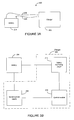
- FIG. 3B illustrates one embodiment of the battery charger of FIG. 3A wherein the battery charger is configured to implement the inventive concept
- FIG. 4 illustrates an implementation of the inventive charging process
- FIG. 5 illustrates one aspect of the inventive regulating process that occurs during the charging process
- FIG. 6 illustrates another aspect of the inventive regulating process that occurs during the charging process
- FIG. 7 illustrates another embodiment of the battery charger that includes a temperature sensor for measuring the battery's temperature
- FIG. 8 illustrates an exemplary implementation of regulating the battery's voltage during the charging process.
- the invention described herein relates to a battery charger that monitors one or more parameters of the battery, and based on the monitored parameters, regulates the charging and or discharging pulses.
- the monitored battery parameters include the terminal voltages of the battery that are indicative of the charge state, as well as the charge absorption rate of the battery.
- the charger maintains one or more of the terminal voltages at selected values by adjusting the charging and/or discharging pulses in manners described below. Basing the charging process on regulated voltages permit the charger to service a wide range of rechargeable batteries in terms of battery types and sizes.
- This advantageous feature is based on the fact that voltage ranges of most rechargeable batteries generally fall somewhere between few volts to few tens of volts—a relatively small range when compared to other battery parameters such as amperage.
- the battery charger described herein is able to tailor the charging process based on a relatively common parameter among a wide variety of batteries. Thus, such an improved battery charger is able to charge a wide variety of batteries.
- FIGS. 1 and 2 illustrate two possible known implementations of pulse charging that may be utilized in conjunction with the inventive concept of regulating one or more battery parameters such as the battery voltage.
- FIGS. 3-8 then illustrate various embodiments and implementations of the invention.
- FIG. 1 illustrates an exemplary charging profile 100 that results from using one embodiment of the invention.
- the charging profile comprises a charge current profile 102 and a battery voltage profile 104 that results from application of the charge current profile 102 to a battery.
- the charge current profile 102 is applied to the battery by a charger that is described below, and comprises a pulse 106 that is applied periodically.
- the pulse 106 is a square pulse with an amplitude 108 and width TC 110 .
- the pulse 106 repeats after a rest period TR 1 112 ; thus, the pulse repetition cycle has a period T of TC+TR 1 . Values of these pulse parameters are variable within their respective ranges, and the pulse parameters are advantageously adjusted to achieve improved battery charging in a manner described below.
- the charge current pulse amplitude 108 has a range of approximately 0 to 20 Coulombs/sec.
- the pulse width TC 110 has a range of approximately 50 to 1000 ms.
- the rest period TR 1 112 has a range of approximately 50 to 1000 ms; thus, the period T has a range of approximately 100 to 2000 ms.
- the battery's terminal voltage is characterized by the voltage profile 104 .
- a voltage V 0 116 represents a quiescent (open circuit) voltage between the battery terminals.
- the battery voltage also increases sharply to V 1 120 due to a sharp increase in the charge influx.
- the charge pulse applies a substantially constant current to the battery during the period TC 110 , the charge content in the battery increases substantially linearly.
- the battery voltage increases substantially linearly to V 2 122 .
- the pulse of charge current is turned off sharply after the period TC 110 , the battery voltage also decreases sharply in response to a level above the rest voltage V 0 .
- FIG. 2 illustrates another exemplary charging profile 130 wherein a charge current profile 132 is applied to the battery that responds with a voltage profile 134 .
- the periodic repetition of square pulses 136 is similar to that described above in reference to FIG. 1 , wherein the pulse 136 has an amplitude 138 and a width TC 146 .
- a single cycle of the charge current profile 132 further comprises a discharge pulse 140 that follows the charge pulse 136 after a first rest period TR 1 144 .
- the discharge pulse 140 has an amplitude 142 and a width D 148 and is followed by a second rest period TR 2 150 that completes the cycle.
- the charge/discharge repetition cycle has a period T of TC+TR 1 +D+TR 2 . Values of these pulse parameters are variable within their respective ranges, and the pulse parameters are advantageously adjusted to achieve improved battery charging in a manner described below.
- the charge current pulse amplitude 138 has a range of approximately 0 to 20 Coulombs/sec.
- the pulse width TC 146 has a range of approximately 50 to 1000 ms.
- the first rest period TR 1 144 has a range of approximately 1 to 20 ms.
- the discharge pulse amplitude 142 has a range of approximately 20 to 200 Coulombs/sec, and the discharge pulse width D 148 has a range of approximately 1 to 20 ms.
- the second rest period TR 2 150 has a range of approximately 50 to 1000 ms.
- the period between pulse set is the sum of the aforementioned time intervals.
- the application of the discharge pulse is known to “shake up” unabsorbed ions that build up near the plate surface inside the battery. By shaking up these unabsorbed ions and pulling them away from the plates (via reverse bias), subsequent charge pulse cycle is better able to deposit ions into the plate.
- the discharge pulse may be achieved by the charger during a non-charging portion of the cycle by providing a temporary load circuit through which the battery can discharge.
- FIG. 2 further illustrates the battery voltage profile 134 in response to the charge current profile.
- the voltage response to the square pulse 136 is similar to that described above in reference to FIG. 1 .
- voltages V 0 154 , V 1 156 , and V 2 160 define the terminal voltages at various transition points of the charging cycle.
- a relaxation transition 162 is similar to its FIG. 1 counterpart 124 aside from being truncated by a reverse bias voltage dip 164 caused by the discharge pulse 140 .
- the battery voltage becomes V 3 166 that is different than the quiescent voltage V 0 154 .
- the voltage V 3 166 relative to V 0 154 is a reflection of the extent discharging of the excess charge of the unabsorbed ions from the battery.
- the battery voltage V 3 166 relaxes to V 0 as the excess charge is drained out into the charger during the non-charging portion of the cycle.
- the aforementioned response of the battery (in terms of voltage) in response to the applied current is also known in the art.
- the voltages V 0 , V 1 , V 2 , V 3 and combinations thereof are some of the indicators of the state of charge of the battery, as well as charge absorption rate of the battery.
- the invention also relates to advantageously adjusting the charge and discharge pulse parameters based on these indicators so as to improve the manner in which batteries are charged.
- FIGS. 3A and B illustrate how a battery may be charged using a charger embodying inventive processes that are described below and whose waveforms are described above.
- FIG. 3A is a simple diagram that shows a charging setup 200 wherein a battery 204 is coupled to a charger 202 by coupler 206 .
- two terminals of the battery 204 are connected via the coupler 206 comprising a pair of cables.
- the battery 204 may be coupled to the charger 204 by the coupler 206 wherein the coupling is via induction.
- a power input to the charger 202 and any load that might be connected to the battery 204 are not shown for simplicity.
- the charger 202 forms a functional relationship with the battery 204 in a manner illustrated in FIG. 3 B.
- the charger 202 comprises functional blocks including a variable power supply 210 , a battery monitoring circuit 212 , and a control module 214 .
- the power supply 210 is coupled to the battery by the coupler 206 (FIG. 3 A).
- the battery monitoring circuit 212 is also coupled to the battery 204 .
- the battery monitoring circuit 212 may reside inside the charger 202 and tap off of the two cables that connect to the battery terminals. Both of the power supply 210 and the battery monitoring circuit 212 are functionally coupled to the control module 214 .
- the control module 214 resides inside or on the charger 202 .
- the control module 214 may reside remotely from the charger itself (communicating by wireless digital signal, for example) without departing from the spirit of the invention.
- the charger 202 described above in reference to FIGS. 3A-B are configured to perform one or more inventive charging processes described below in reference to FIGS. 4-6 .
- the control module 214 in response to battery parameter(s) measured by the monitoring circuit 212 and effected by the power supply 210 , performs the various charging processes described below.
- the process regulates various voltages of the battery during the charging cycle by adjusting the charging pulses. As previously described, regulating the voltage during the charging process permits the charger to adapt to a wide variety of rechargeable batteries.
- FIGS. 4-6 now describe inventive aspects of battery charging process that may be achieved using the aforementioned charger that charges the battery using the pulse cycles described above in reference to FIGS. 1-2 .
- FIG. 4 illustrates a high level description of a battery charging process 220 .
- the process 220 starts at state 222 , and in state 224 that follows, the charger determines one or more battery parameters. Specific examples of these parameters are described below in greater detail.
- the charger determines whether charging should be performed in a decision state 226 . If the answer is “no”, a fault is declared in state 230 , after which any number of remedial actions can be taken in state 232 .
- Some examples of remedial actions for batteries unsuitable for charging include performing a cold cranking amp (CCA) test, and performing a burn-in, both processes whose general principles are known in the art.
- CCA cold cranking amp
- the process enters and remains in a loop until the process determines that charging should not continue.
- the charger monitors the battery parameters in state 234 , and in state 236 that follows, the charger adjusts and applies charging pulses to regulate the battery parameters.
- the charger determines whether to continue charging in a decision state 240 . If the answer is “yes” then the process loops back to state 234 for further monitoring and charging. If the answer is “no” then the charger stops charging in state 242 .
- the charger may stop the charging process, for example, when the process determines that the battery is charged to a predetermined “full” level.
- the cessation of charging may comprise a complete stoppage of monitoring and current application, or having the charger go into a charge maintenance mode so as to keep the battery's charge “topped off” until the battery is removed from the charger, wherein both of these cessation modes are generally known in the art.
- FIG. 5 now illustrates an exemplary process 250 for adaptive regulated pulse charging performed by the charger 202 of FIG. 3 utilizing the charging profile (square pulses) of FIG. 1 .
- the process 250 represents states 234 and 236 of the generalized charging process described above in reference to FIG. 4 , and utilizes voltages V 0 and V 2 as the indicators of the charge state and absorption rate of the battery.
- the quiescent voltage V 0 is a rough indicator of the charge state of the battery
- the maximum voltage V 2 during the application of input charge to the battery (relative to V 0 ), V 2 -V 0 , is indicative of the charge absorption rate.
- these battery voltages are regulated to remain at substantially constant values or within specified ranges by adjusting the charging pulse parameters in a manner described below.
- V 0 can be effectively regulated by adjusting the width of the pulse, especially near the end of the charging process.
- V 2 -V 0 (referred to as charging voltage) can be effectively regulated by adjusting the amplitude of the charging pulse.
- the charger applies test pulses to the battery to determine pulse amplitude and width that result in terminal voltages being at predetermined values V 0 _selected and (V 2 -V 0 )_selected.
- the pulse may be adjusted by changing the amplitude, width, period between pulses, or some combination thereof.
- the battery monitoring circuit measures V 0 , V 1 , and V 2 , and based on the measurement, performs regulation of the quiescent voltage V 0 in step 256 and regulation of charging voltage V 2 -V 0 in step 264 .
- the process then continues in a loop that goes back to the monitoring state 254 that now measures the voltages in response to the adjustments performed in the regulation steps 256 and 264 .
- the looping process continues until charging stops.
- the quiescent voltage V 0 regulating step 256 that follows the monitoring state 254 comprises a decision state 258 that determines if V 0 is substantially equal to V 0 _selected. If the answer is “yes”, the existing charging pulse width is maintained in state 260 after which the process continues on to perform the charging voltage regulation step 264 . If the answer is “no”, the width of the pulse is adjusted in state 262 , after which the process continues on to perform the charging voltage regulation step 264 . In state 262 , the pulse width is adjusted such that if V 0 is less than V 0 _selected (indicating initial or early portion of charging), the width is increased by a selected amount so as to increase the amount of charge being injected into the battery during each cycle.
- the width is decreased by a selected amount.
- the predetermined quiescent voltage value V 0 _selected is set at approximately 13.5 volts when the charger is connected to a 12 volt battery.
- the pulse width is adjusted in increments (or decrements) of approximately 10 ms.
- the charging voltage V 2 -V 0 regulating step 264 that follows step 256 comprises a decision state 266 that determines if V 2 -V 0 is substantially equal to (V 2 -V 0 )_selected. If the answer is “yes”, the existing charging pulse amplitude is maintained in state 268 after which the process continues on loop back to state 254 . If the answer is “no”, the amplitude of the pulse is adjusted in state 270 , after which the process continues on to loop back to state 254 . In state 270 , the pulse amplitude is adjusted such that if V 2 -V 0 is less than (V 2 -V 0 )_selected (indicating that the charging process is near completion), the amplitude is increased by a selected amount.
- V 2 -V 0 is greater than (V 2 -V 0 )_selected (indicating initial or early portion of charging)
- the amplitude is decreased by a selected amount.
- the predetermined charging voltage value (V 2 -V 0 )_selected is set and regulated at approximately 1.0 volt.
- the pulse amplitude is adjusted in increments (or decrements) of approximately 0.05 Coulomb/sec.
- a duty cycle of the charging process changes.
- the duty cycle refers to a ratio of time spent performing a duty to the period of the cycle.
- duty cycle in the pulse charging process comprises a ratio of the charging pulse width to the period.
- the duty cycle of the pulse charger is an accurate indication of the battery's charging state. As the battery fills up with charge, the duty cycle generally decreases.
- duty cycle is generally independent of the type of battery. Thus in one aspect of the invention, duty cycle is monitored while regulating the quiescent voltage V 0 so as to determine the state of charge of a wide range of batteries.
- the charging pulse is preferably adjusted during the latter portion of the charging process such that the pulse width decreases and the amplitude increases.
- application of short charging pulses during the latter portion of the charging process is a more efficient method of introducing charge into the battery.
- the charging process of the invention by increasing the pulse amplitude while shortening the pulse duration, advantageously achieves such an efficient charging while maintaining a high charge content of the pulse afforded by the high amplitude.
- maintaining such a high charge input is afforded by regulating the battery voltages. Regulating a voltage in essence automatically adjusts the current in response to changing condition of the battery. In particular, internal resistance of the battery changes as the battery is being charged. If a traditional charger modulates its current being introduced into the battery, implementation of shortening the pulse duration and increasing the pulse amplitude simultaneously is substantially difficult, and as a result, the charging pulses near the end of the charging process may not achieve high charge input into the battery.
- FIG. 6 now illustrates a charging process 272 that can be implemented utilizing the charge/discharge cycle described above in reference to FIG. 2 .
- the inventive concept of regulating the battery's voltages during pulse charging is applied to the discharging pulse.
- One advantageous result is an optimized discharging during each cycle such that “just enough” excess charge is removed from the battery so as to improve subsequent absorption of ions into the plates.
- excessive discharging is not desired since some of the drained charge needs to replaced during the following charging cycle.
- One indication of excessive discharging is manifested in voltage V 3 ( FIG. 2 ) being less than V 0 .
- insufficient discharging is also not desired since the excess charge of the ions blocking the plates reduces subsequent ion absorption.
- One indication of insufficient discharging is manifested in voltage V 3 being greater than V 0 by a selected amount.
- the discharging pulse can be utilized efficiently.
- the regulation of V 3 -V 0 is performed by adjusting the amplitude of the discharge pulse. It will be appreciated that other parameters of the discharge pulse, such as the duration of the pulse, may be implemented in V 3 -V 0 regulation in a similar manner without departing from the spirit of the invention.
- the charging process 272 begins in state 274 , wherein the charger applies test charge pulses to determine charging pulse and discharging pulse parameters that result in terminal voltages being at predetermined values V 0 _selected, (V 2 -V 0 )_selected, and (V 3 -V 0 )_selected.
- state 276 the battery monitoring circuit measures voltages V 0 , V 1 , V 2 , and V 3 .
- the process then, in step 276 , performs regulations of V 0 and (V 2 -V 0 ) in a manner similar to steps 256 and 264 described above in reference to FIG. 5 .
- the charging process then performs regulation of post-discharge voltage V 3 -V 0 in step 280 that comprises a decision state 282 that determines whether V 3 -V 0 is equal to (V 3 -V 0 )_selected. If the answer is “yes”, the existing amplitude for discharge pulse is maintained in state 284 after which the process loops back to state 276 . If the answer is “no”, the amplitude of discharging pulse is adjusted in state 286 after which the process loops back to state 276 . In state 276 , the discharge pulse amplitude is decreased if V 3 -V 0 is less than (V 3 -V 0 )_selected as a result of excessive discharging.
- the discharge pulse amplitude is increased if V 3 -V 0 is greater than (V 3 -V 0 )_selected as a result of insufficient discharging.
- the predetermined post-discharge voltage (V 3 -V 0 )_selected is set at approximately 0.2 volt.
- the discharge pulse amplitude is adjusted in increments (or decrements) of approximately 0.05 Coulomb/sec.
- FIGS. 7 and 8 illustrate another aspect of the invention, wherein a non-voltage parameter of the battery is regulated in a similar manner.
- a non-voltage parameter of the battery is regulated in a similar manner.
- FIG. 7 illustrates a temperature sensing charger 300 coupled to a battery 330 .
- the charge 300 comprises a variable power supply 302 , a battery monitoring circuit 304 , and a control module 306 that are intercoupled to each other and coupled to the battery in a manner similar to that described above in reference to FIG. 3 B.
- the charger 300 further comprises a temperature sensor 308 that measures a temperature associated with the battery 330 .
- temperature can vary significantly throughout the battery.
- temperature of the core of the battery is typically different than the temperature of the case.
- the temperature sensor measures the case temperature of the battery. It will be appreciated, however, that other battery temperatures including the core temperature may be measured and utilized without departing from the spirit of the invention.
- the battery monitoring circuit 304 is adapted to measure the temperature signal from the temperature sensor 308 .
- FIG. 8 now illustrates a charging process 310 that regulates the battery temperature by adjusting the charging (and/or discharging) pulse.
- the process 310 begins in state 312 wherein the charger applies test charge pulses to determine battery's reference voltages that result in acceptable battery temperature limits temp_low and temp_high.
- the battery's reference voltages may include, but is not limited to, V 0 _selected, (V 2 -V 0 )_selected, and/or (V 3 -V 0 )_selected referred to above in reference to FIGS. 4-6 .
- the battery monitoring circuit measures battery's temperature.
- the charger then regulates battery's temperature in step 316 that comprises a decision state 318 that determines if the measured temperature is within the limits temp_low and temp_high. If the answer is “yes”, existing reference voltages for the battery are maintained in state 320 after which the process loops back to state 314 . If the answer is “no”, the measured temperature is outside of the acceptable range. Thus, in state 322 the battery's reference voltages are adjusted, after which the process loops back to state 314 . In one implementation, if the measured temperature is lower than temp_low (indicating that the battery can be charged at a greater rate), the charging voltage reference (V 2 -V 0 )_selected is increased by 0.1 volt (e.g., from 1.0 volt to 1.1 volt). Conversely, if the measured temperature is higher than temp_high (indicating that battery is warming up), (V 2 -V 0 )_selected is decreased by 0.1 volt (e.g., from 1.0 volt to 0.9 volt).
Abstract
Description
Claims (66)
Priority Applications (4)
| Application Number | Priority Date | Filing Date | Title |
|---|---|---|---|
| US10/099,932 US6841974B2 (en) | 2001-03-13 | 2002-03-13 | Battery charging method |
| TW091134510A TW588491B (en) | 2002-03-13 | 2002-11-27 | Battery charging method |
| PCT/US2003/007476 WO2003079514A1 (en) | 2002-03-13 | 2003-03-12 | Battery charging method |
| AU2003241275A AU2003241275A1 (en) | 2002-03-13 | 2003-03-12 | Battery charging method |
Applications Claiming Priority (2)
| Application Number | Priority Date | Filing Date | Title |
|---|---|---|---|
| US27573501P | 2001-03-13 | 2001-03-13 | |
| US10/099,932 US6841974B2 (en) | 2001-03-13 | 2002-03-13 | Battery charging method |
Publications (2)
| Publication Number | Publication Date |
|---|---|
| US20040032237A1 US20040032237A1 (en) | 2004-02-19 |
| US6841974B2 true US6841974B2 (en) | 2005-01-11 |
Family
ID=28039715
Family Applications (1)
| Application Number | Title | Priority Date | Filing Date |
|---|---|---|---|
| US10/099,932 Expired - Fee Related US6841974B2 (en) | 2001-03-13 | 2002-03-13 | Battery charging method |
Country Status (4)
| Country | Link |
|---|---|
| US (1) | US6841974B2 (en) |
| AU (1) | AU2003241275A1 (en) |
| TW (1) | TW588491B (en) |
| WO (1) | WO2003079514A1 (en) |
Cited By (30)
| Publication number | Priority date | Publication date | Assignee | Title |
|---|---|---|---|---|
| US20050099162A1 (en) * | 2003-11-06 | 2005-05-12 | Yi Ding | System and method for charging a battery |
| US20060086472A1 (en) * | 2004-10-27 | 2006-04-27 | Kimberly-Clark Worldwide, Inc. | Soft durable paper product |
| US20090243556A1 (en) * | 2008-03-31 | 2009-10-01 | Vanner, Inc. | System and method for monitoring the state of charge of a battery |
| US20100164437A1 (en) * | 2008-10-24 | 2010-07-01 | Mckinley Joseph P | Battery formation and charging system and method |
| US20100264879A1 (en) * | 2009-04-20 | 2010-10-21 | Khoon Cheng Lim | Battery Chargers, Electrical Systems, and Rechargeable Battery Charging Methods |
| US8368357B2 (en) | 2010-06-24 | 2013-02-05 | Qnovo Inc. | Method and circuitry to adaptively charge a battery/cell |
| US8638070B2 (en) | 2010-05-21 | 2014-01-28 | Qnovo Inc. | Method and circuitry to adaptively charge a battery/cell |
| US8907631B1 (en) | 2013-07-31 | 2014-12-09 | Qnovo Inc. | Adaptive charging technique and circuitry for a battery/cell using multiple charge circuits and temperature data |
| TWI464997B (en) * | 2012-05-02 | 2014-12-11 | Wistron Corp | Battery charging circuit |
| US8970178B2 (en) | 2010-06-24 | 2015-03-03 | Qnovo Inc. | Method and circuitry to calculate the state of charge of a battery/cell |
| US9035623B1 (en) | 2013-01-23 | 2015-05-19 | Qnovo Inc. | Monitor and control circuitry for charging a battery/cell, and methods of operating same |
| US9063018B1 (en) | 2012-10-22 | 2015-06-23 | Qnovo Inc. | Method and circuitry to determine temperature and/or state of health of a battery/cell |
| US9142994B2 (en) | 2012-09-25 | 2015-09-22 | Qnovo, Inc. | Method and circuitry to adaptively charge a battery/cell |
| US20160064957A1 (en) * | 2014-08-29 | 2016-03-03 | Fairchild Semiconductor Corporation | Optimized charging apparatus and methods |
| US20160204624A1 (en) * | 2015-01-12 | 2016-07-14 | Potential Diference, Inc. | Rapid battery charging |
| US9461492B1 (en) | 2013-04-19 | 2016-10-04 | Qnovo Inc. | Method and circuitry to adaptively charge a battery/cell using a charge-time parameter |
| US20170264105A1 (en) * | 2016-03-08 | 2017-09-14 | Lucas STURNFIELD | Method and apparatus for electric battery temperature maintenance |
| US20180013306A1 (en) * | 2016-07-10 | 2018-01-11 | Gbatteries Energy Canada Inc. | Modulated pulse charging |
| US10067198B2 (en) | 2010-05-21 | 2018-09-04 | Qnovo Inc. | Method and circuitry to adaptively charge a battery/cell using the state of health thereof |
| US10069313B2 (en) * | 2016-07-10 | 2018-09-04 | Gbatteries Energy Canada Inc. | Modulated pulse charging and discharging of a reconfigurable battery pack |
| US10193369B2 (en) | 2017-01-05 | 2019-01-29 | Gbatteries Energy Canada Inc. | Active battery management system |
| US10193366B2 (en) * | 2015-01-12 | 2019-01-29 | Potential Difference, Inc. | Rapid battery charging |
| US10250045B2 (en) | 2017-01-05 | 2019-04-02 | Gbatteries Energy Canada Inc. | System and method for battery pack |
| US10389156B2 (en) | 2010-05-21 | 2019-08-20 | Qnovo Inc. | Method and circuitry to adaptively charge a battery/cell |
| US10574079B1 (en) | 2014-06-20 | 2020-02-25 | Qnovo Inc. | Wireless charging techniques and circuitry for a battery |
| US10840725B2 (en) | 2016-07-10 | 2020-11-17 | Gbatteries Energy Canada Inc. | Battery charging with charging parameters sweep |
| US11397215B2 (en) | 2010-05-21 | 2022-07-26 | Qnovo Inc. | Battery adaptive charging using battery physical phenomena |
| US11397216B2 (en) | 2010-05-21 | 2022-07-26 | Qnovo Inc. | Battery adaptive charging using a battery model |
| US11499291B2 (en) * | 2017-01-19 | 2022-11-15 | Jonas HEINZLER | Work machine |
| US11791647B2 (en) | 2010-05-21 | 2023-10-17 | Qnovo Inc. | Method and circuitry to adaptively charge a battery/cell |
Families Citing this family (16)
| Publication number | Priority date | Publication date | Assignee | Title |
|---|---|---|---|---|
| FR2908243B1 (en) * | 2006-11-06 | 2009-02-13 | Commissariat Energie Atomique | METHOD FOR MANAGING THE CHARGE OF A RECHARGEABLE BATTERY |
| NZ551097A (en) * | 2006-11-06 | 2009-09-25 | Power Man Technologies Nz Ltd | Battery management apparatus |
| US8134300B2 (en) * | 2008-08-08 | 2012-03-13 | Mag Instrument, Inc. | Portable lighting devices |
| RU2437190C2 (en) * | 2009-08-07 | 2011-12-20 | Геннадий Дмитриевич Платонов | Storage battery restoration method and device for its implementation |
| TWI408863B (en) * | 2010-04-21 | 2013-09-11 | Univ Nat Taiwan Science Tech | Smart charging method |
| US8436587B2 (en) * | 2010-05-05 | 2013-05-07 | Ove T. Aanensen | Bipolar overvoltage battery pulser and method |
| CN102904323B (en) * | 2011-07-26 | 2015-03-25 | 神基科技股份有限公司 | Pulse wave modulation charging method and pulse wave modulation charging device |
| TWI450083B (en) * | 2011-09-09 | 2014-08-21 | Ghing Hsin Dien | Power management apparatus |
| US9531200B2 (en) | 2011-10-03 | 2016-12-27 | Megapulse Australia Pty Ltd | Battery conditioning apparatus |
| US9450452B2 (en) | 2012-04-03 | 2016-09-20 | Micorsoft Technology Licensing, LLC | Transformer coupled current capping power supply topology |
| WO2014022267A1 (en) * | 2012-07-30 | 2014-02-06 | Primus Power Corporation | Pulse charging of a grid interactive battery system |
| KR101935364B1 (en) * | 2012-09-26 | 2019-01-07 | 삼성전자주식회사 | apparatus and method for charging rechargeable battery |
| US10033210B2 (en) | 2014-01-30 | 2018-07-24 | Micrsoft Technology Licensing, LLC | Power supply for use with a slow-response power source |
| CN107394294B (en) * | 2017-07-20 | 2018-09-04 | 浙江谷神能源科技股份有限公司 | For the systems of lithium ion battery charge and discharge, control device and associated method |
| DE102017218263A1 (en) * | 2017-10-12 | 2019-04-18 | Robert Bosch Gmbh | Method for charging an electrical energy store |
| FR3107145B1 (en) * | 2020-02-06 | 2022-01-14 | Psa Automobiles Sa | IMPULSIVE CHARGING PROCESS IN VOLTAGE REGULATION WITH VARIABLE AMPLITUDE LEVELS |
Citations (13)
| Publication number | Priority date | Publication date | Assignee | Title |
|---|---|---|---|---|
| US3597673A (en) | 1969-06-26 | 1971-08-03 | Mcculloch Corp | Rapid charging of batteries |
| US4242627A (en) | 1977-12-05 | 1980-12-30 | Edmund Kisiel | Battery charger |
| US4746852A (en) | 1984-10-29 | 1988-05-24 | Christie Electric Corp. | Controller for battery charger |
| US4829225A (en) | 1985-10-23 | 1989-05-09 | Electronic Power Devices, Corp. | Rapid battery charger, discharger and conditioner |
| US5307000A (en) | 1992-01-22 | 1994-04-26 | Electronic Power Technology, Inc. | Method and apparatus for charging, thawing, and formatting a battery |
| US5617005A (en) | 1994-08-04 | 1997-04-01 | Brown, Jr.; Fon R. | Method and apparatus for charging lead acid batteries |
| US5838142A (en) | 1995-10-02 | 1998-11-17 | Impex Patrick Wyss | Battery charger and a process for automatic adjusting operation of a battery charger |
| US5998970A (en) | 1997-07-04 | 1999-12-07 | Hitachi Koki Co., Ltd. | Battery charging operation and a detection of a fully charged condition of the charged battery |
| US6031359A (en) | 1996-10-10 | 2000-02-29 | Chartec Laboratories A/S | Digitally controlled switch mode power supply for charging rechargeable batteries |
| US6043631A (en) | 1998-01-02 | 2000-03-28 | Total Battery Management, Inc. | Battery charger and method of charging rechargeable batteries |
| US6094033A (en) * | 1998-10-02 | 2000-07-25 | Georgia Tech Research Corporation | Battery state of charge detector with rapid charging capability and method |
| US6377028B1 (en) * | 1990-10-23 | 2002-04-23 | Texas Instruments Incorporated | System for charging monitoring batteries for a microprocessor based method |
| US6573687B2 (en) * | 1998-11-24 | 2003-06-03 | Matsushita Electric Industrial Co., Ltd. | Charging/discharging control method for secondary battery |
Family Cites Families (4)
| Publication number | Priority date | Publication date | Assignee | Title |
|---|---|---|---|---|
| US5523667A (en) * | 1992-01-27 | 1996-06-04 | Feldstein; Robert S. | Alkaline battery charger and method of operating same |
| US5561360A (en) * | 1994-05-02 | 1996-10-01 | General Motors Corporation | Battery cycle life improvements through bifurcated recharge method |
| US6040685A (en) * | 1996-08-16 | 2000-03-21 | Total Battery Management, Inc. | Energy transfer and equalization in rechargeable lithium batteries |
| US5900718A (en) * | 1996-08-16 | 1999-05-04 | Total Battery Management, | Battery charger and method of charging batteries |
-
2002
- 2002-03-13 US US10/099,932 patent/US6841974B2/en not_active Expired - Fee Related
- 2002-11-27 TW TW091134510A patent/TW588491B/en not_active IP Right Cessation
-
2003
- 2003-03-12 AU AU2003241275A patent/AU2003241275A1/en not_active Abandoned
- 2003-03-12 WO PCT/US2003/007476 patent/WO2003079514A1/en not_active Application Discontinuation
Patent Citations (13)
| Publication number | Priority date | Publication date | Assignee | Title |
|---|---|---|---|---|
| US3597673A (en) | 1969-06-26 | 1971-08-03 | Mcculloch Corp | Rapid charging of batteries |
| US4242627A (en) | 1977-12-05 | 1980-12-30 | Edmund Kisiel | Battery charger |
| US4746852A (en) | 1984-10-29 | 1988-05-24 | Christie Electric Corp. | Controller for battery charger |
| US4829225A (en) | 1985-10-23 | 1989-05-09 | Electronic Power Devices, Corp. | Rapid battery charger, discharger and conditioner |
| US6377028B1 (en) * | 1990-10-23 | 2002-04-23 | Texas Instruments Incorporated | System for charging monitoring batteries for a microprocessor based method |
| US5307000A (en) | 1992-01-22 | 1994-04-26 | Electronic Power Technology, Inc. | Method and apparatus for charging, thawing, and formatting a battery |
| US5617005A (en) | 1994-08-04 | 1997-04-01 | Brown, Jr.; Fon R. | Method and apparatus for charging lead acid batteries |
| US5838142A (en) | 1995-10-02 | 1998-11-17 | Impex Patrick Wyss | Battery charger and a process for automatic adjusting operation of a battery charger |
| US6031359A (en) | 1996-10-10 | 2000-02-29 | Chartec Laboratories A/S | Digitally controlled switch mode power supply for charging rechargeable batteries |
| US5998970A (en) | 1997-07-04 | 1999-12-07 | Hitachi Koki Co., Ltd. | Battery charging operation and a detection of a fully charged condition of the charged battery |
| US6043631A (en) | 1998-01-02 | 2000-03-28 | Total Battery Management, Inc. | Battery charger and method of charging rechargeable batteries |
| US6094033A (en) * | 1998-10-02 | 2000-07-25 | Georgia Tech Research Corporation | Battery state of charge detector with rapid charging capability and method |
| US6573687B2 (en) * | 1998-11-24 | 2003-06-03 | Matsushita Electric Industrial Co., Ltd. | Charging/discharging control method for secondary battery |
Cited By (59)
| Publication number | Priority date | Publication date | Assignee | Title |
|---|---|---|---|---|
| US20050099162A1 (en) * | 2003-11-06 | 2005-05-12 | Yi Ding | System and method for charging a battery |
| US7221125B2 (en) * | 2003-11-06 | 2007-05-22 | Y. Ding | System and method for charging a battery |
| US20060086472A1 (en) * | 2004-10-27 | 2006-04-27 | Kimberly-Clark Worldwide, Inc. | Soft durable paper product |
| US20090243556A1 (en) * | 2008-03-31 | 2009-10-01 | Vanner, Inc. | System and method for monitoring the state of charge of a battery |
| WO2009151737A1 (en) * | 2008-03-31 | 2009-12-17 | Vanner, Inc. | System and method for monitoring the state of charge of a battery |
| US8154252B2 (en) | 2008-03-31 | 2012-04-10 | Vanner, Inc. | System and method for monitoring the state of charge of a battery |
| US20100164437A1 (en) * | 2008-10-24 | 2010-07-01 | Mckinley Joseph P | Battery formation and charging system and method |
| US20100264879A1 (en) * | 2009-04-20 | 2010-10-21 | Khoon Cheng Lim | Battery Chargers, Electrical Systems, and Rechargeable Battery Charging Methods |
| US8598845B2 (en) * | 2009-04-20 | 2013-12-03 | Valence Technology, Inc. | Battery chargers, electrical systems, and rechargeable battery charging methods |
| US10389156B2 (en) | 2010-05-21 | 2019-08-20 | Qnovo Inc. | Method and circuitry to adaptively charge a battery/cell |
| US11397216B2 (en) | 2010-05-21 | 2022-07-26 | Qnovo Inc. | Battery adaptive charging using a battery model |
| US10067198B2 (en) | 2010-05-21 | 2018-09-04 | Qnovo Inc. | Method and circuitry to adaptively charge a battery/cell using the state of health thereof |
| US8638070B2 (en) | 2010-05-21 | 2014-01-28 | Qnovo Inc. | Method and circuitry to adaptively charge a battery/cell |
| US11063459B2 (en) | 2010-05-21 | 2021-07-13 | Qnovo Inc. | Method and circuitry to adaptively charge a battery/cell |
| US11791647B2 (en) | 2010-05-21 | 2023-10-17 | Qnovo Inc. | Method and circuitry to adaptively charge a battery/cell |
| US9385555B2 (en) | 2010-05-21 | 2016-07-05 | Qnovo Inc. | Method and circuitry to determine the relaxation time of a battery/cell |
| US9373972B2 (en) | 2010-05-21 | 2016-06-21 | Qnovo Inc. | Method and circuitry to determine the relaxation time of a battery/cell |
| US8975874B2 (en) | 2010-05-21 | 2015-03-10 | Qnovo Inc. | Method and circuitry to adaptively charge a battery/cell |
| US11728525B2 (en) | 2010-05-21 | 2023-08-15 | Qnovo Inc. | Battery adaptive charging |
| US11397215B2 (en) | 2010-05-21 | 2022-07-26 | Qnovo Inc. | Battery adaptive charging using battery physical phenomena |
| US8368357B2 (en) | 2010-06-24 | 2013-02-05 | Qnovo Inc. | Method and circuitry to adaptively charge a battery/cell |
| US9121910B2 (en) | 2010-06-24 | 2015-09-01 | Qnovo Inc. | Method and circuitry to adaptively charge a battery/cell using the state of health thereof |
| US9035621B2 (en) | 2010-06-24 | 2015-05-19 | Qnovo Inc. | Method and circuitry to calculate the state of charge of a battery/cell |
| US8970178B2 (en) | 2010-06-24 | 2015-03-03 | Qnovo Inc. | Method and circuitry to calculate the state of charge of a battery/cell |
| US8791669B2 (en) | 2010-06-24 | 2014-07-29 | Qnovo Inc. | Method and circuitry to calculate the state of charge of a battery/cell |
| US8513921B2 (en) | 2010-06-24 | 2013-08-20 | Qnovo Inc. | Method and circuitry to adaptively charge a battery/cell |
| US8427112B2 (en) | 2010-06-24 | 2013-04-23 | Qnovo Inc. | Method and circuitry to calculate the state of charge of a battery/cell |
| US9791513B2 (en) | 2010-06-24 | 2017-10-17 | Qnovo Inc. | Method and circuitry to adjust, correct and/or compensate an SOC of a battery based on relaxation time thereof |
| US9702940B2 (en) | 2011-02-04 | 2017-07-11 | Qnovo Inc. | Method and circuitry to calculate the state of charge of a battery/cell |
| US10128678B2 (en) | 2011-02-04 | 2018-11-13 | Qnovo Inc. | Method and circuitry to adaptively charge a battery/cell |
| TWI464997B (en) * | 2012-05-02 | 2014-12-11 | Wistron Corp | Battery charging circuit |
| US9142994B2 (en) | 2012-09-25 | 2015-09-22 | Qnovo, Inc. | Method and circuitry to adaptively charge a battery/cell |
| US9787122B2 (en) | 2012-09-25 | 2017-10-10 | Qnovo Inc. | Method and circuitry to adaptively charge a battery/cell |
| US9726554B1 (en) | 2012-10-22 | 2017-08-08 | Qnovo Inc. | Method and circuitry to determine temperature and/or state of health of a battery/cell |
| US9063018B1 (en) | 2012-10-22 | 2015-06-23 | Qnovo Inc. | Method and circuitry to determine temperature and/or state of health of a battery/cell |
| US9035623B1 (en) | 2013-01-23 | 2015-05-19 | Qnovo Inc. | Monitor and control circuitry for charging a battery/cell, and methods of operating same |
| US9461492B1 (en) | 2013-04-19 | 2016-10-04 | Qnovo Inc. | Method and circuitry to adaptively charge a battery/cell using a charge-time parameter |
| US10447055B1 (en) | 2013-04-19 | 2019-10-15 | Qnovo Inc. | Method and circuitry to adaptively charge a battery/cell using a charge-time parameter |
| US9912181B2 (en) | 2013-07-31 | 2018-03-06 | Qnovo Inc. | Adaptive charging technique and circuitry for a battery/cell using multiple charge circuits and temperature data |
| US8907631B1 (en) | 2013-07-31 | 2014-12-09 | Qnovo Inc. | Adaptive charging technique and circuitry for a battery/cell using multiple charge circuits and temperature data |
| US10574079B1 (en) | 2014-06-20 | 2020-02-25 | Qnovo Inc. | Wireless charging techniques and circuitry for a battery |
| US10090695B2 (en) * | 2014-08-29 | 2018-10-02 | Fairchild Semiconductor Corporation | Optimized current pulse charging apparatus and method employing increasing clamp reference voltages and decreasing current pulses |
| US20160064957A1 (en) * | 2014-08-29 | 2016-03-03 | Fairchild Semiconductor Corporation | Optimized charging apparatus and methods |
| US20180287404A1 (en) * | 2015-01-12 | 2018-10-04 | Potential Diference, Inc. | Rapid battery charging |
| US20160204624A1 (en) * | 2015-01-12 | 2016-07-14 | Potential Diference, Inc. | Rapid battery charging |
| US9991726B2 (en) * | 2015-01-12 | 2018-06-05 | Potential Difference, Inc. | Rapid battery charging |
| US10193366B2 (en) * | 2015-01-12 | 2019-01-29 | Potential Difference, Inc. | Rapid battery charging |
| US11075524B2 (en) * | 2015-01-12 | 2021-07-27 | Potential Difference, Inc. | Rapid battery charging |
| US20170264105A1 (en) * | 2016-03-08 | 2017-09-14 | Lucas STURNFIELD | Method and apparatus for electric battery temperature maintenance |
| US11362535B2 (en) | 2016-07-10 | 2022-06-14 | Gbatteries Energy Canada Inc. | Battery charging with charging parameters sweep |
| US10840725B2 (en) | 2016-07-10 | 2020-11-17 | Gbatteries Energy Canada Inc. | Battery charging with charging parameters sweep |
| US10135281B2 (en) * | 2016-07-10 | 2018-11-20 | Gbatteries Energy Canada Inc. | Charging a battery with frequency-modulated pulses based on battery measurements |
| WO2018010019A1 (en) * | 2016-07-10 | 2018-01-18 | Gbatteries Energy Canada Inc. | Modulated pulse charging |
| US10069313B2 (en) * | 2016-07-10 | 2018-09-04 | Gbatteries Energy Canada Inc. | Modulated pulse charging and discharging of a reconfigurable battery pack |
| US20180013306A1 (en) * | 2016-07-10 | 2018-01-11 | Gbatteries Energy Canada Inc. | Modulated pulse charging |
| US10923923B2 (en) | 2017-01-05 | 2021-02-16 | Gbatteries Energy Canada Inc. | System and method for battery pack |
| US10193369B2 (en) | 2017-01-05 | 2019-01-29 | Gbatteries Energy Canada Inc. | Active battery management system |
| US10250045B2 (en) | 2017-01-05 | 2019-04-02 | Gbatteries Energy Canada Inc. | System and method for battery pack |
| US11499291B2 (en) * | 2017-01-19 | 2022-11-15 | Jonas HEINZLER | Work machine |
Also Published As
| Publication number | Publication date |
|---|---|
| AU2003241275A1 (en) | 2003-09-29 |
| WO2003079514A1 (en) | 2003-09-25 |
| US20040032237A1 (en) | 2004-02-19 |
| TW200409433A (en) | 2004-06-01 |
| TW588491B (en) | 2004-05-21 |
Similar Documents
| Publication | Publication Date | Title |
|---|---|---|
| US6841974B2 (en) | Battery charging method | |
| EP0847123B1 (en) | Pulse charging method and a charger | |
| CN101083402B (en) | Method of charging a rechargeable battery and protection circuit for a rechargeable battery | |
| US6043631A (en) | Battery charger and method of charging rechargeable batteries | |
| US5694023A (en) | Control and termination of a battery charging process | |
| CN1998110B (en) | Lithium-ion/polymer lithium battery cell charging method | |
| US8536836B2 (en) | Method for determining the end-of-discharge threshold of a rechargeable battery | |
| JP4121945B2 (en) | Method and apparatus for charging a rechargeable battery with a non-liquid electrolyte | |
| US20090184685A1 (en) | Battery pack and method of charging the same | |
| US6313605B1 (en) | Battery charger and method of charging nickel based batteries | |
| US20080224667A1 (en) | Method for charging battery pack | |
| US11418047B2 (en) | Battery charging method and system depending on ambient temperature | |
| US20060113959A1 (en) | Rechargeable battery life judging method | |
| CN101103487A (en) | Method for the balanced charging of a lithium-ion or lithium-polymer battery | |
| WO2000076049A1 (en) | Battery charger for lithium based batteries | |
| US11431037B2 (en) | Method and system for fast-charging an electrochemical cell and fast-charging controller implemented in this system | |
| MX2010011937A (en) | Improved battery charging device and method. | |
| JP7275452B2 (en) | SECONDARY BATTERY OPERATION CONTROL DEVICE AND METHOD USING RELATIVE DEGREE OF ELECTRODE | |
| AU710799B2 (en) | Control and termination of a battery charging process | |
| JP3539123B2 (en) | Method and apparatus for determining deterioration of secondary battery | |
| KR101497549B1 (en) | Recovering method for charging capacity of battery and the charging device | |
| US6459239B1 (en) | Method and apparatus for recharging batteries in the presence of a load current | |
| JPH07336908A (en) | Charger of nonaqueous secondary battery | |
| JPH09117075A (en) | Charging method for lithium ion secondary battery | |
| JP3738532B2 (en) | Battery charger |
Legal Events
| Date | Code | Title | Description |
|---|---|---|---|
| AS | Assignment |
Owner name: KNOBBE, MARTENS, OLSON & BEAR LLP, CALIFORNIA Free format text: SECURITY INTEREST;ASSIGNOR:HDM SYSTEMS, CORPORATION;REEL/FRAME:015133/0166 Effective date: 20040206 |
|
| AS | Assignment |
Owner name: HDM SYSTEMS CORPORATION, MASSACHUSETTS Free format text: ASSIGNMENT OF ASSIGNORS INTEREST;ASSIGNOR:DYKEMAN, STEVE W.;REEL/FRAME:015146/0732 Effective date: 20020624 |
|
| FEPP | Fee payment procedure |
Free format text: PAYER NUMBER DE-ASSIGNED (ORIGINAL EVENT CODE: RMPN); ENTITY STATUS OF PATENT OWNER: SMALL ENTITY Free format text: PAYOR NUMBER ASSIGNED (ORIGINAL EVENT CODE: ASPN); ENTITY STATUS OF PATENT OWNER: SMALL ENTITY |
|
| FPAY | Fee payment |
Year of fee payment: 4 |
|
| AS | Assignment |
Owner name: NEXT STREET FINANCIAL LLC, MASSACHUSETTS Free format text: SECURITY AGREEMENT;ASSIGNOR:HDM SYSTEMS CORPORATION;REEL/FRAME:028025/0784 Effective date: 20120405 |
|
| FPAY | Fee payment |
Year of fee payment: 8 |
|
| REMI | Maintenance fee reminder mailed | ||
| LAPS | Lapse for failure to pay maintenance fees | ||
| STCH | Information on status: patent discontinuation |
Free format text: PATENT EXPIRED DUE TO NONPAYMENT OF MAINTENANCE FEES UNDER 37 CFR 1.362 |
|
| FP | Lapsed due to failure to pay maintenance fee |
Effective date: 20170111 |