US6841100B2 - Method for casting a concrete product - Google Patents
Method for casting a concrete product Download PDFInfo
- Publication number
- US6841100B2 US6841100B2 US10/659,287 US65928703A US6841100B2 US 6841100 B2 US6841100 B2 US 6841100B2 US 65928703 A US65928703 A US 65928703A US 6841100 B2 US6841100 B2 US 6841100B2
- Authority
- US
- United States
- Prior art keywords
- concrete slab
- feed trough
- slab product
- measurement results
- basis
- Prior art date
- Legal status (The legal status is an assumption and is not a legal conclusion. Google has not performed a legal analysis and makes no representation as to the accuracy of the status listed.)
- Expired - Lifetime
Links
Images


Classifications
-
- B—PERFORMING OPERATIONS; TRANSPORTING
- B28—WORKING CEMENT, CLAY, OR STONE
- B28B—SHAPING CLAY OR OTHER CERAMIC COMPOSITIONS; SHAPING SLAG; SHAPING MIXTURES CONTAINING CEMENTITIOUS MATERIAL, e.g. PLASTER
- B28B1/00—Producing shaped prefabricated articles from the material
- B28B1/08—Producing shaped prefabricated articles from the material by vibrating or jolting
- B28B1/084—Producing shaped prefabricated articles from the material by vibrating or jolting the vibrating moulds or cores being moved horizontally for making strands of moulded articles
-
- B—PERFORMING OPERATIONS; TRANSPORTING
- B28—WORKING CEMENT, CLAY, OR STONE
- B28B—SHAPING CLAY OR OTHER CERAMIC COMPOSITIONS; SHAPING SLAG; SHAPING MIXTURES CONTAINING CEMENTITIOUS MATERIAL, e.g. PLASTER
- B28B17/00—Details of, or accessories for, apparatus for shaping the material; Auxiliary measures taken in connection with such shaping
- B28B17/0063—Control arrangements
- B28B17/0072—Product control or inspection
-
- B—PERFORMING OPERATIONS; TRANSPORTING
- B28—WORKING CEMENT, CLAY, OR STONE
- B28B—SHAPING CLAY OR OTHER CERAMIC COMPOSITIONS; SHAPING SLAG; SHAPING MIXTURES CONTAINING CEMENTITIOUS MATERIAL, e.g. PLASTER
- B28B3/00—Producing shaped articles from the material by using presses; Presses specially adapted therefor
- B28B3/20—Producing shaped articles from the material by using presses; Presses specially adapted therefor wherein the material is extruded
- B28B3/22—Producing shaped articles from the material by using presses; Presses specially adapted therefor wherein the material is extruded by screw or worm
- B28B3/228—Slipform casting extruder, e.g. self-propelled extruder
-
- B—PERFORMING OPERATIONS; TRANSPORTING
- B29—WORKING OF PLASTICS; WORKING OF SUBSTANCES IN A PLASTIC STATE IN GENERAL
- B29C—SHAPING OR JOINING OF PLASTICS; SHAPING OF MATERIAL IN A PLASTIC STATE, NOT OTHERWISE PROVIDED FOR; AFTER-TREATMENT OF THE SHAPED PRODUCTS, e.g. REPAIRING
- B29C48/00—Extrusion moulding, i.e. expressing the moulding material through a die or nozzle which imparts the desired form; Apparatus therefor
- B29C48/25—Component parts, details or accessories; Auxiliary operations
- B29C48/256—Exchangeable extruder parts
- B29C48/2561—Mounting or handling of the screw
-
- B—PERFORMING OPERATIONS; TRANSPORTING
- B29—WORKING OF PLASTICS; WORKING OF SUBSTANCES IN A PLASTIC STATE IN GENERAL
- B29C—SHAPING OR JOINING OF PLASTICS; SHAPING OF MATERIAL IN A PLASTIC STATE, NOT OTHERWISE PROVIDED FOR; AFTER-TREATMENT OF THE SHAPED PRODUCTS, e.g. REPAIRING
- B29C48/00—Extrusion moulding, i.e. expressing the moulding material through a die or nozzle which imparts the desired form; Apparatus therefor
- B29C48/25—Component parts, details or accessories; Auxiliary operations
- B29C48/256—Exchangeable extruder parts
- B29C48/2564—Screw parts
-
- B—PERFORMING OPERATIONS; TRANSPORTING
- B29—WORKING OF PLASTICS; WORKING OF SUBSTANCES IN A PLASTIC STATE IN GENERAL
- B29C—SHAPING OR JOINING OF PLASTICS; SHAPING OF MATERIAL IN A PLASTIC STATE, NOT OTHERWISE PROVIDED FOR; AFTER-TREATMENT OF THE SHAPED PRODUCTS, e.g. REPAIRING
- B29C48/00—Extrusion moulding, i.e. expressing the moulding material through a die or nozzle which imparts the desired form; Apparatus therefor
- B29C48/25—Component parts, details or accessories; Auxiliary operations
- B29C48/36—Means for plasticising or homogenising the moulding material or forcing it through the nozzle or die
- B29C48/50—Details of extruders
- B29C48/505—Screws
- B29C48/63—Screws having sections without mixing elements or threads, i.e. having cylinder shaped sections
-
- B—PERFORMING OPERATIONS; TRANSPORTING
- B29—WORKING OF PLASTICS; WORKING OF SUBSTANCES IN A PLASTIC STATE IN GENERAL
- B29C—SHAPING OR JOINING OF PLASTICS; SHAPING OF MATERIAL IN A PLASTIC STATE, NOT OTHERWISE PROVIDED FOR; AFTER-TREATMENT OF THE SHAPED PRODUCTS, e.g. REPAIRING
- B29C48/00—Extrusion moulding, i.e. expressing the moulding material through a die or nozzle which imparts the desired form; Apparatus therefor
- B29C48/25—Component parts, details or accessories; Auxiliary operations
- B29C48/92—Measuring, controlling or regulating
-
- B—PERFORMING OPERATIONS; TRANSPORTING
- B29—WORKING OF PLASTICS; WORKING OF SUBSTANCES IN A PLASTIC STATE IN GENERAL
- B29C—SHAPING OR JOINING OF PLASTICS; SHAPING OF MATERIAL IN A PLASTIC STATE, NOT OTHERWISE PROVIDED FOR; AFTER-TREATMENT OF THE SHAPED PRODUCTS, e.g. REPAIRING
- B29C2948/00—Indexing scheme relating to extrusion moulding
- B29C2948/92—Measuring, controlling or regulating
- B29C2948/92009—Measured parameter
- B29C2948/92019—Pressure
-
- B—PERFORMING OPERATIONS; TRANSPORTING
- B29—WORKING OF PLASTICS; WORKING OF SUBSTANCES IN A PLASTIC STATE IN GENERAL
- B29C—SHAPING OR JOINING OF PLASTICS; SHAPING OF MATERIAL IN A PLASTIC STATE, NOT OTHERWISE PROVIDED FOR; AFTER-TREATMENT OF THE SHAPED PRODUCTS, e.g. REPAIRING
- B29C2948/00—Indexing scheme relating to extrusion moulding
- B29C2948/92—Measuring, controlling or regulating
- B29C2948/92323—Location or phase of measurement
- B29C2948/92361—Extrusion unit
- B29C2948/92409—Die; Nozzle zone
Definitions
- the present invention relates to a method for making hollow-core concrete products by a slipform casting method, wherein the top surface quality of the product being cast is automatically controlled by adjusting the concrete mix feed trough of the slipform casting machine.
- the invention also relates to a slipform casting machinery for making hollow-core concrete products, the machinery including an adjustable concrete mix feed trough and sensors capable of monitoring the quality of the top surface of the concrete product being manufactured.
- the concrete mix is extruded with the help of auger feeders into a mold or through nozzles, whereby the casting machine is propelled along the casting bed by the reaction forces imposed on the auger feeders.
- the ready-cast product remains on the casting bed.
- the quality of the manufactured concrete product is affected by the adjustments of the casting machine and degree of wear in its components.
- the compaction of the concrete product may be very thorough even when the top surface of the product remains short of its nominal height or has an undulating upper profile.
- Patent publication FI 80,845 describes a concrete mix compaction method. This approach, however, lacks a technique capable of securing the true straightness and correct height of the top surface in the product being made. After a sufficiently large portion of the cross section in the concrete product has reached a satisfactory degree of compaction, the extrusion force exerted on the cross section of the product exceeds the travel resistance imposed on the machine making it to proceed.
- the top surface of the concrete product may remain filled under the nominal height or assume an undulating profile notwithstanding the acceptable degree of compaction.
- the concrete mix feed trough functions as a flow guide for the concrete mix so as to form a portion of the auger feeder casing, whereby the length of the trough can be adjusted so as to control the flow of the concrete mix into the cross section of the product being cast.
- the length of the concrete mix feed trough is set separately for each kind of concrete mix to be cast. Such an adjustment is made on a one-time basis without later correction.
- the flow of the concrete mix subjects the feed trough to a wear particularly at the downstream end thereof. The wear progresses rapidly so far as to affect the flow of the concrete mix and, thereby, the filling of the concrete product cross section. As soon as the top surface of the cast product is found to be defectively filled, the feed trough must be replaced or the worn portion thereof otherwise repaired.
- the straightness and height of the top surface of the concrete product being cast is measured during the slipform casting process.
- the concrete mix feed trough has guides and a position adjustment actuator attached thereto for automatic positioning of the feed trough. This arrangement makes it possible to adjust the feed trough so that the trough either feeds a greater or smaller amount of concrete mix to the top surface of the product being cast.
- the feed trough adjustment takes place longitudinally in the center axis direction of the auger feeder.
- An individually adjustable feed trough is located under each one of the auger feeders.
- the method according to the invention makes it possible to adjust the concrete mix flow automatically with the help of the feed trough in real time during the casting process so as to make the concrete product being cast compliant with the requirements set on the concrete product top surface as to its quality, straightness and height. Additionally, the method according to the invention reduces the need for feed trough repair/replacement and secures uniform casting quality of concrete product with a leveled top surface. At the occurrence of excessive extrusion, the feed trough can be adjusted so as to reduce the flow rate of concrete mix to the top surface region of the product being cast.
- FIG. 1 shows a partially sectional view of a casting apparatus according to the invention.
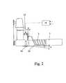
- FIG. 2 shows an alternative embodiment of the invention for adjusting a concrete mix feed trough.
- the apparatus according to the invention shown therein is an extruder-type slipform casting machine adapted to move on support wheels 4 along the side rails of a mold 8 .
- the apparatus is assembled on a framework 5 .
- the casting machine is provided with one or more auger feeders 2 , whereon concrete mix is fed from a hopper 1 .
- the augers 2 are mounted on the framework 5 so as to be supported by rotary auger drive shafts 7 rotated by a drive motor 6 .
- At the trailing end of the augers 2 are adapted core-shaping mandrels 3 serving to shape hollow cores in the concrete product 25 being cast.
- the auger drive shaft(s) 7 is/are connected by a crank mechanism rod 9 to a drive motor 10 of the compaction system.
- the closed cross section of the casting mold is defined at its upper surface by a top-side troweling beam 11 , while side beams 14 define the sides of the mold.
- Under the auger feeder and partially at the sides thereof is located a concrete mix feed trough 12 adapted to have its position in the direction of the longitudinal axis of the auger feeder adjustable by means of an actuator 13 .
- the feed trough is supported by a support bracket 20 and a guide 22 .
- the guide 22 itself is supported by support rolls 21 .
- the height level and straightness of concrete product top surface 19 is monitored by means of a level sensor 15 adapted on a guide rail 16 .
- the level sensor 15 is actuated into a reciprocating movement during casting, whereby it is capable of measuring the product height dimension across the entire top surface of the product and possible depressions therein.
- a control unit 18 compares the height level measurement values with the nominal product height preset in the control unit prior to casting. If the control unit detects deviations in the measured product height from the preset nominal value, the control unit adjusts as necessary the position of the concrete mix feed trough 12 in relation to the downstream end of the auger feeder. Possible elevation of the casting machine frame from the casting bed due to excessive extrusion pressure is detected by a sensor 17 , whereby such an elevation is taken into account in the control signals issued by the control unit 18 to the actuator 13 of the feed trough.
- control unit 18 during casting receives from level sensor 15 a signal indicating that the top-surface height 19 at a hollow-core portion of the product tends to remain lower than the preset nominal height of the product, the control program of control unit 18 steers the feed trough 12 to be moved with the help of actuator 13 further upstream in regard to the auger feeder 2 .
- the relative portion of concrete mix flow to the lower layer of concrete product 25 is reduced and, respectively, increased to the top-surface layer of the product.
- the increased flow rate of concrete mix also imposes a higher extrusion pressure in the upper layer of the concrete product thus filling the depression on the top surface of the product.
- the control program of the control unit steers the feed trough to be moved downstream in regard to the auger feeder, whereby the relative amount of the concrete mix flow on the top surface of the product is decreased, the extrusion pressure in the direction of the product top surface is diminished and the product top surface height is lowered.
- Compensation of wear at the downstream delivery end of the feed trough may also be effected by adjusting the length of feed trough 12 and the stroke length of actuator 13 .
- the control unit can also adjust the position of the feed trough downstream of the auger feeder thus compensating for a change in the relative portion of concrete mix flow due to wear in the feed trough. This facility increases in a substantial fashion the change intervals of feed troughs necessary due to wear.
- Actuator 13 may be electrically or hydraulically powered, whereby in the latter case also a hydraulic unit is needed to deliver pressurized hydraulic fluid.
- the adjustment of the feed trough is realized by arranging the feed trough 23 to be supported by a hinged support 24 . Then, based on the adjustment need decided by control unit 18 , the angle ⁇ of feed trough 23 in regard to the longitudinal axis of auger feeder 2 is changed with the help of actuator 13 .
- control unit 18 receives from level sensor 15 a signal indicating that the top surface height of the product tends to remain lower than the preset nominal height of the product, the angle ⁇ is adjusted smaller, whereby the relative portion of the concrete mix flow to the lower layer of concrete product 25 is reduced and, respectively, increased to the top surface layer of the product.
- the increased flow rate of concrete mix also imposes a higher extrusion pressure in the upper layer of the concrete product thus filling the depression on the top surface of the product.
- the control program of the control unit steers the tilt angle ⁇ of the feed trough toward a steeper position, whereby the relative proportion of the concrete mix flowing to the top layer of the product is decreased, the extrusion pressure in the direction of the product top surface is diminished and the product top surface height is lowered.
- the invention is not limited as to the use of a specific type of level sensor capable of measuring the top-surface height of a concrete product, but rather, may be effected in conjunction with any kind of sensor capable of submitting such measurement information as is required in the position control of a concrete mix feed trough.
Landscapes
- Engineering & Computer Science (AREA)
- Mechanical Engineering (AREA)
- Chemical & Material Sciences (AREA)
- Ceramic Engineering (AREA)
- Manufacturing & Machinery (AREA)
- On-Site Construction Work That Accompanies The Preparation And Application Of Concrete (AREA)
- Devices For Post-Treatments, Processing, Supply, Discharge, And Other Processes (AREA)
Abstract
Description
Claims (12)
Applications Claiming Priority (2)
| Application Number | Priority Date | Filing Date | Title |
|---|---|---|---|
| FI20021649 | 2002-09-16 | ||
| FI20021649A FI114623B (en) | 2002-09-16 | 2002-09-16 | Method and equipment for casting a concrete product |
Publications (2)
| Publication Number | Publication Date |
|---|---|
| US20040051193A1 US20040051193A1 (en) | 2004-03-18 |
| US6841100B2 true US6841100B2 (en) | 2005-01-11 |
Family
ID=8564589
Family Applications (1)
| Application Number | Title | Priority Date | Filing Date |
|---|---|---|---|
| US10/659,287 Expired - Lifetime US6841100B2 (en) | 2002-09-16 | 2003-09-11 | Method for casting a concrete product |
Country Status (5)
| Country | Link |
|---|---|
| US (1) | US6841100B2 (en) |
| EP (1) | EP1398128B1 (en) |
| ES (1) | ES2565027T3 (en) |
| FI (1) | FI114623B (en) |
| NO (1) | NO322248B1 (en) |
Cited By (5)
| Publication number | Priority date | Publication date | Assignee | Title |
|---|---|---|---|---|
| US8068962B2 (en) | 2007-04-05 | 2011-11-29 | Power Curbers, Inc. | 3D control system for construction machines |
| US20140145361A1 (en) * | 2012-11-29 | 2014-05-29 | Elematic Oy Ab | Method and apparatus for casting concrete products |
| RU2541020C1 (en) * | 2013-08-27 | 2015-02-10 | Федеральное государственное бюджетное образовательное учреждение высшего профессионального образования "Оренбургский государственный университет" | Extruder |
| CN106476122A (en) * | 2016-11-28 | 2017-03-08 | 河南省众邦伟业科技有限公司 | Side vibrating device assembly |
| USD1024142S1 (en) | 2022-07-08 | 2024-04-23 | Dianne F. Baxter | Concrete slide |
Families Citing this family (7)
| Publication number | Priority date | Publication date | Assignee | Title |
|---|---|---|---|---|
| FI117130B (en) * | 2001-06-27 | 2006-06-30 | Consolis Technology Oy Ab | Method and apparatus for making concrete product |
| FI20020193A0 (en) * | 2002-02-01 | 2002-02-01 | Addtek Res & Dev Oy Ab | Method and apparatus for casting concrete product |
| RU2293650C1 (en) * | 2005-09-09 | 2007-02-20 | Николай Павлович Селиванов | Method of manufacture of the building structures and the building structure manufactured by this method |
| RU2293651C1 (en) * | 2005-09-09 | 2007-02-20 | Николай Павлович Селиванов | Extruder |
| WO2007114795A1 (en) * | 2006-04-03 | 2007-10-11 | National University Of Singapore | A method and system to design a hollow core concrete panel |
| FI125864B (en) | 2009-09-02 | 2016-03-15 | Pamplona Holding 1 Oy | Apparatus and procedure for casting concrete products |
| CN115125795B (en) * | 2022-05-25 | 2024-03-15 | 济南金曰公路工程有限公司 | Pavement concrete side gap pouring equipment and method |
Citations (11)
| Publication number | Priority date | Publication date | Assignee | Title |
|---|---|---|---|---|
| US3212127A (en) * | 1963-01-23 | 1965-10-19 | Du Pont | Automatic control apparatus for maintaining transverse thickness uniformity of extruded material |
| US3792133A (en) * | 1972-06-30 | 1974-02-12 | Aukerman A Co | Method for slip-forming walls of asymmetrical transverse cross section |
| FI48902B (en) | 1971-08-02 | 1974-10-31 | Toijalan Teraesvalmiste | |
| US4022556A (en) * | 1975-04-30 | 1977-05-10 | The George Hyman Construction Company | Concrete slab extruder having a free flight auger |
| US4202658A (en) * | 1977-08-10 | 1980-05-13 | Paraisten Kalkki Oy-Pargas Kalk Ab | Glide-casting machine for the manufacturing of hollow slabs and equivalent |
| US4723900A (en) | 1985-03-01 | 1988-02-09 | Kt-Suunnittelu Oy | Extruder for casting concrete slabs |
| FI76514B (en) | 1986-04-07 | 1988-07-29 | Kt Suunnittelu Oy | FOERFARANDE OCH ANORDNING FOER GJUTNING AV BETONGELEMENT. |
| US5023030A (en) * | 1988-09-14 | 1991-06-11 | Oy Partek Ab | Method for casting one or several concrete products placed side by side |
| EP0517505A1 (en) | 1991-06-06 | 1992-12-09 | John Anthony Douglas Durham | Method and apparatus for laying a surface material on a prefabricated concrete slab |
| US5198235A (en) * | 1991-03-25 | 1993-03-30 | Reichstein Stuart W M | Apparatus for vertical slipforming of concrete walls |
| US5618476A (en) * | 1995-08-03 | 1997-04-08 | Mogel; Richard L. | Process for slip form production of prestressed concrete railroad ties |
Family Cites Families (3)
| Publication number | Priority date | Publication date | Assignee | Title |
|---|---|---|---|---|
| FI67320C (en) * | 1983-05-09 | 1985-03-11 | Partek Ab | GLOBAL REQUIREMENTS FOR THE CONDUCT OF CONCRETE |
| US5123831A (en) * | 1991-05-16 | 1992-06-23 | Esa Enqvist | Concrete extrusion machine |
| FI19991792A (en) * | 1999-08-23 | 2001-02-24 | Valkeakoski Extec Oy Ltd | Method and arrangement for making a concrete product and a series of concrete products |
-
2002
- 2002-09-16 FI FI20021649A patent/FI114623B/en not_active IP Right Cessation
-
2003
- 2003-09-08 ES ES03396081.6T patent/ES2565027T3/en not_active Expired - Lifetime
- 2003-09-08 EP EP03396081.6A patent/EP1398128B1/en not_active Expired - Lifetime
- 2003-09-11 US US10/659,287 patent/US6841100B2/en not_active Expired - Lifetime
- 2003-09-11 NO NO20034021A patent/NO322248B1/en not_active IP Right Cessation
Patent Citations (12)
| Publication number | Priority date | Publication date | Assignee | Title |
|---|---|---|---|---|
| US3212127A (en) * | 1963-01-23 | 1965-10-19 | Du Pont | Automatic control apparatus for maintaining transverse thickness uniformity of extruded material |
| FI48902B (en) | 1971-08-02 | 1974-10-31 | Toijalan Teraesvalmiste | |
| US3792133A (en) * | 1972-06-30 | 1974-02-12 | Aukerman A Co | Method for slip-forming walls of asymmetrical transverse cross section |
| US4022556A (en) * | 1975-04-30 | 1977-05-10 | The George Hyman Construction Company | Concrete slab extruder having a free flight auger |
| US4202658A (en) * | 1977-08-10 | 1980-05-13 | Paraisten Kalkki Oy-Pargas Kalk Ab | Glide-casting machine for the manufacturing of hollow slabs and equivalent |
| US4723900A (en) | 1985-03-01 | 1988-02-09 | Kt-Suunnittelu Oy | Extruder for casting concrete slabs |
| FI76514B (en) | 1986-04-07 | 1988-07-29 | Kt Suunnittelu Oy | FOERFARANDE OCH ANORDNING FOER GJUTNING AV BETONGELEMENT. |
| US4773838A (en) * | 1986-04-07 | 1988-09-27 | Kt-Suunnittelu Oy | Slipforming extruder for casting concrete slabs |
| US5023030A (en) * | 1988-09-14 | 1991-06-11 | Oy Partek Ab | Method for casting one or several concrete products placed side by side |
| US5198235A (en) * | 1991-03-25 | 1993-03-30 | Reichstein Stuart W M | Apparatus for vertical slipforming of concrete walls |
| EP0517505A1 (en) | 1991-06-06 | 1992-12-09 | John Anthony Douglas Durham | Method and apparatus for laying a surface material on a prefabricated concrete slab |
| US5618476A (en) * | 1995-08-03 | 1997-04-08 | Mogel; Richard L. | Process for slip form production of prestressed concrete railroad ties |
Cited By (7)
| Publication number | Priority date | Publication date | Assignee | Title |
|---|---|---|---|---|
| US8068962B2 (en) | 2007-04-05 | 2011-11-29 | Power Curbers, Inc. | 3D control system for construction machines |
| US8073566B2 (en) | 2007-04-05 | 2011-12-06 | Power Curbers, Inc. | Automated stringline installation system |
| US20140145361A1 (en) * | 2012-11-29 | 2014-05-29 | Elematic Oy Ab | Method and apparatus for casting concrete products |
| RU2541020C1 (en) * | 2013-08-27 | 2015-02-10 | Федеральное государственное бюджетное образовательное учреждение высшего профессионального образования "Оренбургский государственный университет" | Extruder |
| CN106476122A (en) * | 2016-11-28 | 2017-03-08 | 河南省众邦伟业科技有限公司 | Side vibrating device assembly |
| CN106476122B (en) * | 2016-11-28 | 2019-06-14 | 河南省众邦伟业科技有限公司 | Side vibrating device assembly |
| USD1024142S1 (en) | 2022-07-08 | 2024-04-23 | Dianne F. Baxter | Concrete slide |
Also Published As
| Publication number | Publication date |
|---|---|
| FI20021649A0 (en) | 2002-09-16 |
| EP1398128A2 (en) | 2004-03-17 |
| US20040051193A1 (en) | 2004-03-18 |
| FI114623B (en) | 2004-11-30 |
| EP1398128A3 (en) | 2005-09-21 |
| NO322248B1 (en) | 2006-09-04 |
| EP1398128B1 (en) | 2016-02-17 |
| FI20021649A (en) | 2004-03-17 |
| ES2565027T3 (en) | 2016-03-30 |
| NO20034021L (en) | 2004-03-17 |
| NO20034021D0 (en) | 2003-09-11 |
Similar Documents
| Publication | Publication Date | Title |
|---|---|---|
| US6841100B2 (en) | Method for casting a concrete product | |
| US9163366B2 (en) | Slipform paver | |
| US5030079A (en) | Roller die extrusion and calendering apparatus | |
| CN104975554A (en) | Self-propelled construction machine and method for controlling the same | |
| KR100770253B1 (en) | Calibration method of slide declination for press machine and apparatus for said method | |
| FI79738C (en) | Executable track stop leveling and directional machine | |
| CN1043193C (en) | Method for the controlled pre-rolling of thin slabs leaving a continuous casting plant, and relative device | |
| JPS6353325B2 (en) | ||
| FI113850B (en) | Method and apparatus for casting concrete products | |
| US20140145361A1 (en) | Method and apparatus for casting concrete products | |
| CA1193834A (en) | Extrusion machine | |
| EP0685595B1 (en) | Stone metering system for railroad track maintenance vehicle | |
| KR101185201B1 (en) | Slab scarfing apparatus and thereof method | |
| EP1843882B1 (en) | Method and apparatus for casting a concrete product by slipform casting | |
| EP3303705A1 (en) | Spreading device for a road-construction mass substance | |
| US20110094624A1 (en) | Adzer skid assembly and method of use | |
| CN219276182U (en) | Powder distributing equipment | |
| DE60309691T2 (en) | CASTING DEVICE AND METHOD | |
| CN213684153U (en) | Cable trench trolley | |
| US20070137829A1 (en) | Moulding sand supply apparatus and method | |
| JPS60254Y2 (en) | clay extruder | |
| EP2292397B1 (en) | Apparatus and method for casting a concrete product by slipform casting | |
| CN116746700A (en) | Thick slurry method wafer tape casting device | |
| JPS5947061A (en) | Casting device provided with automatic charging device | |
| CZ299U1 (en) | Device for making shaped concrete slabs |
Legal Events
| Date | Code | Title | Description |
|---|---|---|---|
| AS | Assignment |
Owner name: CONSOLIS TECHNOLOGY OY AB, FINLAND Free format text: ASSIGNMENT OF ASSIGNORS INTEREST;ASSIGNOR:SEPPANEN, AIMO;REEL/FRAME:014501/0769 Effective date: 20030821 |
|
| STCF | Information on status: patent grant |
Free format text: PATENTED CASE |
|
| FPAY | Fee payment |
Year of fee payment: 4 |
|
| AS | Assignment |
Owner name: ELEMATIC GROUP OY AB, FINLAND Free format text: ASSIGNMENT OF ASSIGNORS INTEREST;ASSIGNOR:CONSOLIS TECHNOLOGY OY AB;REEL/FRAME:026999/0369 Effective date: 20081113 |
|
| AS | Assignment |
Owner name: AVATON OY, FINLAND Free format text: CHANGE OF NAME;ASSIGNOR:ELEMATIC GROUP OY;REEL/FRAME:027120/0039 Effective date: 20090419 |
|
| FPAY | Fee payment |
Year of fee payment: 8 |
|
| FEPP | Fee payment procedure |
Free format text: PAYOR NUMBER ASSIGNED (ORIGINAL EVENT CODE: ASPN); ENTITY STATUS OF PATENT OWNER: LARGE ENTITY |
|
| FPAY | Fee payment |
Year of fee payment: 12 |