US6834108B1 - Method for improving acoustic noise attenuation in hand-free devices - Google Patents
Method for improving acoustic noise attenuation in hand-free devices Download PDFInfo
- Publication number
- US6834108B1 US6834108B1 US09/622,270 US62227001A US6834108B1 US 6834108 B1 US6834108 B1 US 6834108B1 US 62227001 A US62227001 A US 62227001A US 6834108 B1 US6834108 B1 US 6834108B1
- Authority
- US
- United States
- Prior art keywords
- echo
- attenuation
- filter
- wiener filter
- frequency
- Prior art date
- Legal status (The legal status is an assumption and is not a legal conclusion. Google has not performed a legal analysis and makes no representation as to the accuracy of the status listed.)
- Expired - Lifetime
Links
Images
Classifications
-
- H—ELECTRICITY
- H04—ELECTRIC COMMUNICATION TECHNIQUE
- H04M—TELEPHONIC COMMUNICATION
- H04M9/00—Arrangements for interconnection not involving centralised switching
- H04M9/08—Two-way loud-speaking telephone systems with means for conditioning the signal, e.g. for suppressing echoes for one or both directions of traffic
Definitions
- the present invention relates to a method for improving the acoustic sidetone suppression in hands-free telephones, having a level discriminator, frequency-selective, controllable echo cancellation with subband processing and a residual-error post filtering.
- This object is achieved with the aid of a method having the features of Patent Claim 1 .
- Advantageous refinements of this method are specified in the subclaims.
- the echo cancellation is preferably implemented by means of a filter bank in frequency subbands.
- both power-based estimates and correlation-based analyses are used for controlling the adaptation or step size.
- both the echo cancellers and the residual-error post filtering to supply the estimated values for the return loss introduced by them, since these estimated values can preferably be used for controlling the attenuation of the level discriminator. Consequently, the attenuation to be introduced by the level discriminator can be further reduced, and thus the call quality can be further improved in the case of duplex.
- duplex It is additionally preferred to detect the simultaneous activity of both call participants (duplex). It is then possible, for example, to reduce the overall attenuation of the level discriminator in the case of duplex, in order further to improve the full duplex mode of the hands-free telephone.
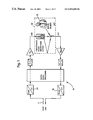
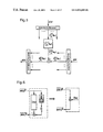
- FIG. 1 shows a simplified model of a hands-free telephone with connection to a digital link
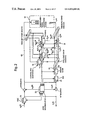
- FIG. 2 shows a block diagram of the hands-free telephone according to the invention
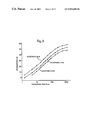
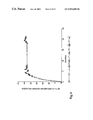
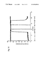
- FIG. 3 shows curves for the attenuation requirements placed on the hands-free telephone, as a function of the echo propagation time
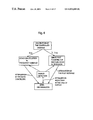
- FIG. 4 shows an overview of the method according to the invention
- FIG. 5 shows the structure of the adaptation of the subband echo cancellers
- FIG. 6 shows a model presentation for the power transmission factors
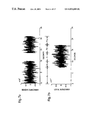
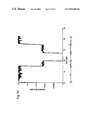
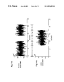
- FIG. 7 shows an illustration of the signals of the remote and the local subscriber with the aid of which the method according to the invention is explained below;
- FIG. 8 shows the excitation resulting therefrom, and the disturbed error in band 1 ;
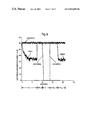
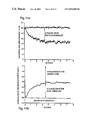
- FIG. 9 shows the estimated power transmission factor under the conditions in accordance with
- FIG. 10 shows the step size, selected by the step-size controller in band 1 under the conditions in accordance with FIGS. 7 and 8;
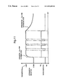
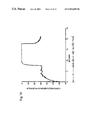
- FIG. 11 shows the smoothing according to the invention of the attenuation reduction
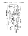
- FIG. 12 shows a detailed illustration of the post filtering of the error signals
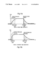
- FIG. 13 shows the smoothing according to the invention of the step sizes (part A for equal time constants, part B for different time constants);
- FIG. 14 shows a further example of the signals of the remote and the local subscribers, on which the processing in the further figures is based;
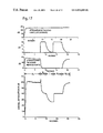
- FIG. 15 shows the compensation characteristic and the attenuation by the further filter in band 1 ;
- FIG. 16 shows the attenuation by the further filter in band 1 ;
- FIG. 17 shows the transfer of the attenuation values to the level discriminator
- FIG. 18 shows the excitation power and error power in the overall band (in each case for the input signal characteristic in accordance with FIG. 14 ).
- FIG. 1 A simplified model of a hands-free telephone 10 with connection to a digital link 12 is illustrated in FIG. 1 .
- the A Law coding or decoding used in the European ISDN network is illustrated in the two left-hand blocks 14 , 16 .
- Sketched on the right-hand side is the loudspeaker/room microphone system 18 (LRM system) with the local call participant 20 , the user of the hands-free telephone.
- LRM system loudspeaker/room microphone system
- the acoustic coupling between the loudspeaker and the microphone causes crosstalk via the LRM system.
- This crosstalk is received by the remote subscriber as an objectionable echo.
- acoustic waves emerge from the loudspeaker and propagate in the room. Reflection at the walls and other objects located in the room produce a plurality of propagation paths which give rise to different propagation times of the loudspeaker signal.
- the echo signal at the microphone therefore comprises the overlapping of a multiplicity of echo components and, as the case may be, the useful signal n(t): the local talker.
- Termination echoes which are produced in telephones with an analogue interface owing to mismatching of the artificial line to the line impedance can be left out of consideration in the case of the use of digital links.
- FIG. 2 An overview of a hands-free telephone is illustrated in FIG. 2 .
- the central element is a level discriminator 22 which is illustrated in the left-hand part of FIG. 2 .
- two automatic gain controls (AGC) 24 , 26 can be connected into the transmitting path and the receiving path.
- the level discriminator 22 guarantees the minimum attenuations prescribed by the ITU or ETSI recommendations by inserting attenuations into the transmitting path and/or the receiving path as a function of the call situation.
- the receiving path is cleared and a signal of the remote subscriber is output on the loudspeaker without attenuation.
- the echoes produced in the case of disconnected or poorly compensated cancellers are greatly reduced by the attenuation inserted into the transmitting path. The situation is reversed in the case of activity of the local talker.
- the level discriminator 22 inserts no attenuation into the transmitting path, and the signal of the local talker is transmitted without attenuation. Controlling the level discriminator becomes more difficult in the duplex case.
- both paths and thus also the subscriber signals
- both paths receive half the attenuation to be inserted, or in the case of non-optimum control at least one of the two signal paths is attenuated. Consequently, duplex is not possible, or possible only in a restricted fashion.
- adaptive echo cancellers 28 illustrated in the right-hand part of FIG. 2 —provides a remedy here. These attempt to balance the LRM system digitally, in order then to remove the echo component of the remote subscriber from the microphone signal. The overall attenuation to be inserted by the level discriminator can be reduced depending on how well the cancellers accomplish this.
- the echo cancellation was implemented in frequency subbands, the width of the individual bands preferably being between 250 Hz and 500 Hz given an 8 kHz sampling rate, or between 500 Hz and 1000 Hz given a 16 kHz sampling rate.
- the system can be operated as a multi-rate system by using undersampling and oversampling, the result being a reduction in the computational outlay.
- the “cancellation power” can be distributed differently over the individual frequency bands owing to the subband breakdown, the result being to achieve effective adaptation of the “cancellation power” to voice signals.
- the subband processing has a decorrelating action when the overall band processing is compared with the individual subband systems.
- the propagation time is determined chiefly by the image-processing components. Since the aim in general is to output the image and sound of the remote subscriber to the local subscriber with the lips synchronized, the propagation time of the acoustic echoes can increase to several hundred milliseconds.
- FIG. 3 illustrates the results of a study in which an attempt was made to find out which return loss dependent on the propagation time of this echo is necessary so that 90, 70 or 50 percent of those asked would be satisfied with the call quality.
- the control of the echo cancellers is performed in several stages. All performance-based control units 32 operate for each compensator autonomously, that is to say independently of the remaining frequency bands. Consequently, in FIG. 2 a dedicated adaptation and control unit 32 is sketched in for each compensator.
- the control stage based on correlation analyses of the loudspeaker and microphone signals is used to detect duplex, and therefore evaluated in like fashion in all frequency bands.
- a further stage takes account of the accuracy as limited by the fixed point calculation and controls the adaptation as a function of the drive level.
- the final duplex detection is likewise performed separately with the aid of a dedicated unit which is based both on the detectors of the level discriminator and on those of the echo cancellers.
- This unit causes the level discriminator to reduce once again the overall attenuation to be inserted (in accordance with ITU Recommendation G.167) in duplex situations.
- the central element in this case is the calculation of the step-size vector ⁇ overscore ( ⁇ ) ⁇ (k).
- the latter is used both for controlling the subband echo cancellers and for calculating the coefficients of the post-filter.
- the two partial methods in each case calculate the return loss caused by them and communicate this information to the level discriminator 22 .
- the discriminator 22 then reduces the overall attenuation set by the user, and inserts only the residual attenuation into the transmitting and receiving paths, respectively.
- the present invention relates to the combination of the abovementioned Wiener filtering and the adaptation control of the subband echo cancellers, the two methods are described in detail in separate chapters.
- a novel feature of the approach presented is the use of a single controlled variable—the step-size vector ⁇ overscore ( ⁇ ) ⁇ (k)—for both methods.
- the computational outlay thereby reduced (less than 100 cycles/sampling clock pulse for the post filtering) renders it possible to implement both methods on cost-effective “consumer” signal processors, and thereby to increase the quality of the hands-free telephone.
- the frequency band analysis and synthesis required for the subband processing is implemented as a polyphase filter bank.
- First step is to describe a step-size control which ensures quick and stable adaptation of the subband echo cancellers. Also presented are methods which estimate the return loss achieved.
- the level discriminator 22 can therefore reduce the overall attenuation—doing so on the basis of these estimated values. It is of no consequence in this case for the estimation of attenuation whether the attenuation is achieved by well compensated echo cancellers, by the acoustic arrangement of loudspeaker and microphone, or by an appropriate selection of the analogue gains.
- the adaptation of the subband echo cancellers is carried out by means of an NLMS method adapted to the signal processor used.
- a structural illustration of the adaptation process is reproduced in FIG. 5 in order to explain the notation of the following description.
- the index ⁇ is intended here to indicate the subband number.
- e ⁇ ( r ) _ ⁇ ( k r ) y ⁇ ( r ) _ ⁇ ( k r ) - y ⁇ ⁇ ( r ) _ ⁇ ( k r ) ( 3.2 )
- This error is composed of a so-called undisturbed error ⁇ ⁇ ( r ) _ ⁇ ( k r )
- c _ ⁇ ( r ) _ ⁇ ( k r + 1 ) c _ ⁇ ( r ) _ ⁇ ( k r ) + F ⁇ ( ⁇ ⁇ ( r ) ⁇ ( k r ) ⁇ ⁇ _ ⁇ ( r ) _ ⁇ ( k r ) ⁇ e ⁇ ( r ) ′ _ ⁇ ( k r ) ⁇ _ ⁇ ( r ) H _ ⁇ ( k r ) ⁇ _ ⁇ ( r ) _ ⁇ ( k ) ) , ( 3.4 )
- the coefficients of the subband echo cancellers are constantly adapted to the subband pulse responses of the LRM system during operation of the hands-free telephone by using the adaptation methods. It is possible thereby to achieve a reduction in the acoustic echo even after system changes.
- the setting criterion for the adaptation method used is the minimization of the mean square error.
- the coefficients experience a substantial change when the samples of the cancelled signal e ⁇ ( r ) _ ⁇ ( k r )
- the adaptive filters are poorly adapted to the spatial pulse response after changes in the LRM system. There is then no reduction in the acoustic echoes, or only a very slight one—the uncompensated echo components effect an enlargement of the signals e ⁇ ( r ) _ ⁇ ( k r ) .
- the cancellers should be adapted as quickly as possible in such situations.
- n(k) for example in the case of activity of the local talker—likewise enlarges the signals e ⁇ ( r ) _ ⁇ ( k r ) .
- this component is the useful signal to be transmitted, whereas for the adaptive filter it constitutes interference which can lead to false setting of the coefficients. In such situations, the cancellers should not be adjusted, or be adjusted only slightly, so that the compensation already achieved is not worsened again.
- the parallel circuit of LRM system and echo canceller including the subtraction point is modelled to a first approximation as a simple attenuator.
- the model assumes in this case that there are no additional interference signals—such as activity of the local talker, for example—in the LRM system.
- the set K ES,FT was introduced in equation 3.8 for this reason. This set is intended to contain the instants at which a hands-free telephone is in the state of simplex of the remote subscriber.
- Non-linear, recursive smoothings are used for the first partial problem.
- the sum of the absolute value of the real part and the absolute value of the imaginary part of the subband signals is selected as input signals of these filters.
- the power factors are calculated logarithmically in order to avoid division—the division can therefore be replaced by a subtraction.
- a so-called correlation measure ⁇ ( ⁇ v ) is used for the second partial problem.
- a normalized cross-correlation analysis of the excitation signal of the remote subscriber and the microphone signal is carried out in this case.
- the two signals are strongly correlated, and the correlation measure delivers values ⁇ ( ⁇ r ) ⁇ 1.
- the correlation is reduced, and values ⁇ ( ⁇ r ) ⁇ 1 are detected.
- the microphone signal is formed by convolution of the excitation signal with the already presented pulse response of an office room (length of 2044 coefficients at a sampling rate of 8 kHz) and subsequent addition of the signal of the local talker.
- the mean powers of the excitation and error signals are illustrated in FIG. 8 .
- the adaptation was carried out with the aid of the step size control described below, it being assumed that the correlation evaluations deliver cleardowns only in the regions A 1 and A 2 . It is clearly to be seen in the illustration that the compensation achieved in the course of phase A 1 of approximately 25 dB can be held over the regions of the duplex and simplex of the local subscriber.
- the mean powers of the excitation signal and of the undisturbed error signal must be estimated in order to determine the power transmission factor in the ⁇ th subband.
- ⁇ x ⁇ ⁇ xr ⁇ ⁇ if ⁇ ⁇ ⁇ x ⁇ ( r ) _ ⁇ ( k r ) ⁇ > ⁇ ⁇ ⁇ ( r ) _ ⁇ ( k r - 1 ) ⁇ _ ⁇ xf ⁇ ⁇ otherwise
- the power transmission factors are determined only logarithmically—the division is thereby reduced to two logarithmations and one subtraction.
- log ( r ) ⁇ ( k r ) _ ⁇ ⁇ P ⁇ p ⁇ , log ( r ) ⁇ ( k r ) + ( 1 - ⁇ P ) ⁇ p ⁇ , log ( r ) ⁇ ( k r - 1 ) _ ⁇ for ⁇ ⁇ k r ⁇ K ES .
- the logarithmation is denoted in this case by LOG ⁇ . . . ⁇ .
- the time constant ⁇ p was likewise selected differently for rising and falling edges. The aim thereby is to do justice to the non-cancellable part of the system run time (artificial delay of the microphone signal). Because of this run time, the signal power of the excitation signal drops earlier than that of the error signal—without correction of this process, the estimation would carry out a reduction in the estimated value after each excitation phase.
- the time constants are increased upon detection of duplex. The duplex detector used is described further below.
- K GS is intended in this case to denote the instants at which the above-described detector detects duplex.
- the set K ES,FT denotes the instants at which the correlation measure detects simplex of the remote subscriber.
- FIG. 9 Its estimation is not renewed in the regions B 1 , C and B 2 , since no cleardowns are delivered here by the correlation measure. By comparison with FIG. 8, a good agreement between the desired and estimated values is to be seen. The power difference between excitation and error is to be seen in this case as the desired value. Both the characteristic and the final value, to be seen in FIG. 8, of approximately 26-30 dB are well simulated in the estimate.
- ⁇ ⁇ ⁇ ( r ) ⁇ ( k r ) LIN ⁇ ⁇ LOG ⁇ ⁇ ⁇ x ⁇ ( r ) ⁇ ( k r ) ⁇ _ ⁇ + p ⁇ . log ( r ) ⁇ ( k r ) - LOG ⁇ ⁇ ⁇ e ⁇ ( r ) _ ⁇ ( k p ) ⁇ _ ⁇ ⁇ ( 3.22 )
- LIN ⁇ . . . ⁇ denotes the linearization. If the excitation power undershoots a limit
- the step size in the first subband is illustrated logarithmically in FIG. 10 .
- the step size is approximately 1—in phases of the simplex of the local subscriber (B 1 and B 2 ) it is possible to determine from FIG. 8 a difference from disturbed to undisturbed error power from approximately 26 to 30 dB. Accordingly, the step size is in the expected region (approximately ⁇ 27 dB) in the duplex phases, as well.
- the target detector should be able to decide between simplex and duplex independently of spatial changes and also independently of the power of the input signals.
- a correlation measure a detector—which fulfils the above requirements.
- the cross correlation between the loudspeaker signal and the microphone signal is evaluated in a normalized form.
- the numerator and denominator of the above equation must be evaluated in this case with double-word accuracy (32 bits).
- a cleardown is set whenever the maximum of the determined correlation measures is greater than a limiting value ⁇ 0 .
- the evaluations were carried out only in the most powerful, first subband, and there also only with the real parts of the complex signals.
- the largest signal-to-noise ratio is to be expected in this band in the case of voice excitation and this should improve the reliability of the detector results.
- the calculations are carried out only every r sampling clock pulses owing to the undersampling.
- the instant k r is then accepted into the set K ES,FT if one of the L 2 comparisons yields a correlation measure greater than ⁇ 0 .
- the return loss to be delivered by the hands-free telephone can be reduced by 15 dB in duplex situations.
- a duplex detector was developed in accordance with the following considerations for this reason. At the same time, this detector can be used for the purpose of setting the estimates in the step-size control “more carefully” when duplex occurs.
- the detection of duplex is carried out in two steps. It is checked in a first step whether the remote talker is active. For this purpose, the excitation signal, smoothed in terms of absolute value, of the remote subscriber is compared with a threshold
- the second comparison is always necessary when the level discriminator introduces large attenuation values (for example after spatial changes). The receiving path can be strongly damped in such situations. Here, the comparison with the smoothed input signal would not yield a reliable result.
- ⁇ xg ⁇ ⁇ xgr , if ⁇ ⁇ ⁇ ⁇ ⁇ ( k - N ) ⁇ > ⁇ ⁇ ⁇ ( k - 1 ) ⁇ _ ⁇ xgf , otherwise where ⁇ ⁇ 0 ⁇ ⁇ xg ⁇ ⁇ xgr ⁇ 1. ( 3.30 )
- the delay of N clock pulses was introduced in order to compensate the propagation time of the analysis/synthesis system again during the comparisons in the second detector stage. This does not require any additional memory, since the analysis filter stores the last N signal values of the input signal in any case.
- a comparison is carried out between the performance of the estimated, undisturbed error and the measurable, disturbed error.
- the power estimates are reduced again to absolute-value smoothings and the determination of a power transfer factor.
- a lo ⁇ ( r ) ⁇ 1 , if ⁇ ⁇ LOG ⁇ ⁇ ⁇ e ⁇ ( rk r ) ⁇ _ ⁇ - p GS > LOG ⁇ ⁇ ⁇ x ⁇ ( rk r ) ⁇ _ ⁇ + p EK ( r ) ⁇ ( k r ) _ . 0 , otherwise ( 3.35 )
- the reduction in the required attenuation is performed by smoothing using low pass filters.
- the time constant for the rising edge ⁇ GSr should be as small as possible, in order not to cut off the beginning of a voice passage.
- the time constant for the falling edge ⁇ GSf should be selected to be greater than the rise constant, so that the attenuation reduction p GS ( f ) ⁇ ( k r ) _
- the instant k r is accepted into the set K gs if the attenuation reduction is above a predetermined value.
- An exemplary characteristic of the attenuation reduction is illustrated in FIG. 11 .
- the overall attenuation of the level discriminator which is prescribed by the ITU-T recommendation G. 167, can be reduced by the attenuation of the overall system of room and echo canceller. Even in the case when echo cancellation is switched off, the control described estimates the transfer factor of the acoustic link from the loudspeaker to the microphone, including the analogue gains. As a result, it is possible to react to different loudspeaker gains and different (analogue) microphone gains, and to (digitally) adapt the overall attenuation in accordance with the required values. In the duplex case, the overall attenuation can be set to a smaller value, likewise in accordance with the ITU-T recommendation G. 167. A detector and an appropriate transfer variable was also presented or defined for this purpose. The overall attenuation of the level discriminator D PW (k) is therefore controlled (initially without taking account of the post filtering) according to the following method:
- D 0 is the required maximum attenuation (for example 45 dB) in this case.
- the spatial pulse responses are generally longer than the echo cancellers, as a result of which a residual error remains.
- the NLMS algorithm tracks the adaptive filters only at a finite speed—echoes are once again more strongly perceptible until the final compensation is reached once again.
- the error signal e(k) also contains the non-cancelled component of the remote talker, which has already been denoted as “undisturbed” error ⁇ (k) in the preceding parts of this description.
- the signal n(k) is the useful component of the signal e(k)—the signal ⁇ (k) is the interference, from this point of view.
- the derivation returns simple controlled variables with the aid of which the “influence” of the Wiener filter can be controlled as a function of the cancellation power of the adaptive filters.
- the attenuation inserted by these methods can also be estimated with low outlay, and be “communicated” to the level discriminator.
- the filter ⁇ right arrow over (g) ⁇ (k) 30 is placed downstream of the synthesis.
- the order of the filter may be M ⁇ 1, which means that M coefficients must be set.
- the filter 30 is to release the “disturbed” signal e(k) optimally from the “interference” ⁇ (k).
- the signals of the remote and local subscribers are regarded as being uncorrelated. Furthermore, it is assumed that the signals n(k) and ⁇ (k) are averageless, owing to the high-pass filtering of the line input signal and microphone signal.
- ⁇ ⁇ ⁇ M 2 ⁇ ⁇ ⁇ ⁇ ⁇ where ⁇ ⁇ ⁇ ⁇ 0 ⁇ ⁇ ... ⁇ ⁇ M - 1 ⁇
- G opt ⁇ ( ⁇ ⁇ ) 1 - S EC ⁇ ( ⁇ ⁇ ) S n ⁇ ⁇ t ⁇ ( ⁇ ⁇ ) .
- the frequencies ⁇ ⁇ also simultaneously represent the band centres of the previously described bandpass filters in the case of subband decomposition.
- S EC ⁇ ( ⁇ ⁇ ) S n ⁇ ⁇ t ⁇ ( ⁇ ⁇ ) it is possible to have recourse to corresponding variables in the individual subbands when estimating the variable S EC ⁇ ( ⁇ ⁇ ) S n ⁇ ⁇ t ⁇ ( ⁇ ⁇ ) .
- ⁇ right arrow over( ⁇ overscore ( ⁇ ) ⁇ ) ⁇ (r) ( k ) ( ⁇ o (r) ( k ), ⁇ 1 (r) ( k ) . . . , ⁇ 7 (r) ( k ), 1, ⁇ 7 (r) ( k ), . . . , ⁇ 1 (r) ( k )) ⁇ .
- the estimated interpolation points of the filter frequency response are time-smoothed, and provided with a so-called overestimation factor ⁇ and a maximum attenuation G min (k).
- ⁇ ⁇ ( r ) _ ⁇ ( k ) ( 1 - y r , f ) ⁇ ⁇ ⁇ ( r ) ⁇ ( k ) + ⁇ r , f ⁇ ⁇ ⁇ ( r ) _ ⁇ ( k - 1 ) where ⁇ ⁇ ⁇ ⁇ ⁇ 0 ⁇ ⁇ ... ⁇ ⁇ ( M 2 - 1 ) ⁇ .
- the step size ⁇ (k) may be set to a value close to one—the step size may remain at this value to the end of the voice sequence for the sake of simplicity, and the step size is set to zero again subsequently.
- the vector ⁇ overscore ( ⁇ ) ⁇ (r) (k) used in the implementation is therefore composed of the smoothed step sizes: ⁇ _ ( r ) ⁇ ( k ) ⁇ ( ⁇ n ( r ) _ ⁇ ( k ) , ⁇ 1 ( p ) _ ⁇ ( k ) , ... ⁇ , ⁇ 1 ( r ) _ ⁇ ( k ) , 1 , ⁇ 7 ( r ) _ ⁇ ( k ) , ... ⁇ , ⁇ 1 ( p ) _ ⁇ ( k ) r .
- G n ( v ) ⁇ ( k ) Max ⁇ ⁇ ( 1 - ⁇ ⁇ ⁇ ⁇ a ( r ) _ ⁇ ( k ) ⁇ , G mn ⁇ ( k ) ⁇ ⁇ ⁇ where ⁇ ⁇ n ⁇ ⁇ 0 ⁇ ⁇ ... ⁇ ⁇ ( M - 1 ) ⁇ ( 4.1 )
- the overestimation factor ⁇ accelerates the introduction of the attenuation, and it enlarges the attenuation.
- a value of between 1.0 and 3.0 is preferably selected for ⁇ .
- the Wiener filter should be able to intervene strongly and to introduce large attenuations (for example up to 45 dB in accordance with the ITU recommendations).
- the Wiener filter certainly suppresses the echoes, but the remote subscriber then perceives a type of modulation of the background noise.
- the noise is transmitted without attenuation in his voice pauses, and while he is speaking it is subjected to attenuation (for example to a level of 45 dB).
- the step size control delivers a suitable controlled variable—the estimated power transfer factor D EK (k).
- the setting of the parameter G min (k) is therefore performed in accordance with:
- LIN denotes the linearization, already used in the step size control, of logarithmic variables.
- the maximum insertion loss (for example 45 dB) can be set with the parameter G max,log .
- This fixed value is then reduced by the attenuation D EK (k), which the echo cancellers perform on average, and by the duplex reduction D GS (k).
- the variables D EK (k) and D GS (k) are present in the same logarithmic form as the constant G max,log .
- the limitation of the calculated variable to 0 dB serves the purpose of adaptation to the linearization.
- the attenuation D w (k) of the signal e(k) by the Wiener filter is communicated to the level discriminator via an interface by analogy with the attenuation of the echo cancellers and the attenuation reduction in the case of duplex.
- LOG denotes the normalization or logarithmation already used in the step size control. It ensures communication with the level discriminator which is specific in terms of interface. The division by 8 is achieved by 3 bits.
- D W ( r ) _ ⁇ ( k ) ⁇ r , f ⁇ D W ( r ) _ ⁇ ( k - 1 ) + ( 1 - ⁇ r , f ) ⁇ D W ( r ) ⁇ ( k ) .
- the use of different time constants for rising and falling edges has the effect that the estimate is “more cautious”. If the Wiener filter inserts attenuation, the level discriminator reduces its attenuation more slowly. The error signal is therefore attenuated in the short term more than the required 45 dB. If the Wiener filter reduces its attenuation, by contrast, the level discriminator very quickly inserts the residual attenuation.
- the time delay by the synthesis filtering can also lead here to a short term overall attenuation of more than the set upper limit (for example 45 dB).
- the maximum attenuation G max,log was selected at 60 dB.
- the initial compensating operation of the cancellers takes place in the region A 1 .
- the cancellers are not yet compensated—while at the end the final compensated state is achieved in all bands. Since no duplex takes place in this phase, the Wiener filter should insert the difference between 60 dB and the attenuation which is achieved,by the echo cancellers. For this purpose, FIG.
- the attenuation is not immediately inserted—this effect is partially balanced out again by the transformation into the time domain and the intermediate synthesis filtering. Consequently, at the start of the activity of the remote talker an attenuation of 25 dB is nevertheless already inserted in the overall band signal (see FIG. 18 ). After approximately 200 ms, the attenuation has then already been increased to its final value of 60 dB.
- the Wiener filter in band 1 With increasing compensation of the canceller, the attenuation by the Wiener filter in band 1 is reduced and, as expected, reaches a final value of approximately 30 dB (60 dB maximum limitation ⁇ 30 dB return loss through the canceller). Since the Wiener filter was not inserted until after the synthesis, the characteristics of the excitation, the error, the step size and the power transfer factor in band 1 can be taken from FIGS. 9 and 10.
- the overall signal e(k) is to be separated from its interference ⁇ (k). Since the local subscriber—the useful signal in e(k)—is not active, however, the overall signal consists only of the interference. If the limitation were to be omitted in the case of the determination of the coefficients G 1 ( r ) ⁇ ( k ) ,
- FIG. 16 illustrates the attenuation, inserted by the Wiener filter, in band 1 .
- the initial value of approximately 60 dB is determined by the maximum attenuation G max,log set.
- the cancellers initialized with zero vectors at the start of the simulation perform compensation in the course of phase A 1 , and thereby reduce the upper limit of the attenuation to be introduced to approximately 30 dB.
- this upper limit is reduced once again, by 15 dB, by the duplex detector to now only approximately 15 dB.
- this limit is not reached, because the power of the local talker is far above that of the residual echo.
- the determining variable in the duplex phase is the power ratio of the signal of the local talker and the residual echo of the remote talker.
- the power of the residual echo is a function, on the one hand, of the excitation power of the remote subscriber and, on the other hand, of the compensated state of the cancellers. The better these are compensated, the less will be the influence of the Wiener filter in these passages.
- FIG. 17 plots the characteristics of the estimate of the attenuations by the echo cancellers and by the Wiener filter, as well as the reduction in the case of duplex. The sum of these three variables is transferred to the level discriminator and is illustrated in the lower part of FIG. 17 . This estimate can be compared with the actual signal characteristics of the excitation and the error in the overall band in FIG. 18 . In regions B 1 and B 2 , the duplex detector detects the activity of the two subscriber ends, and increases the attenuation transfer by 15 dB.
- the step size is reduced and the Wiener filter reduces its attenuation.
- the step size is set to zero in the passages without excitation (region C) of the remote subscriber—the Wiener filter thereby acts only as a time-delay element.
- an upper limit of the attenuation was determined in accordance with equation 4.1.
- This upper limit was determined as a function of the attenuation already achieved, which is given by the power transfer factors in the respective band or by the duplex attenuation.
- both variables are calculated and stored only in logarithmic representation. Eight linearizations are therefore required in order to be able to use the variables in the limiting function. The determination of the maximum values would therefore require more computing power than the entire remaining calculation of coefficients. For this reason, a uniform upper limit was introduced for all bands. This limit is likewise calculated in accordance with equation 4.1, but with the overall band variables.
- the resources required for the post filtering resulting therefrom is far below 1 MIPS in the case of the use of 16-bit fixed point signal processors.
- the overall attenuation can additionally be weakened by the attenuation of the Wiener filter 30 .
- the maximum excursion of the level discriminator can therefore be specified by
Abstract
Description


Claims (11)
Applications Claiming Priority (3)
| Application Number | Priority Date | Filing Date | Title |
|---|---|---|---|
| DE19806015A DE19806015C2 (en) | 1998-02-13 | 1998-02-13 | Process for improving acoustic attenuation in hands-free systems |
| DE19806015 | 1998-02-13 | ||
| PCT/DE1999/000151 WO1999041897A2 (en) | 1998-02-13 | 1999-01-21 | Method for improving acoustic noise attenuation in hand-free devices |
Publications (1)
| Publication Number | Publication Date |
|---|---|
| US6834108B1 true US6834108B1 (en) | 2004-12-21 |
Family
ID=7857681
Family Applications (1)
| Application Number | Title | Priority Date | Filing Date |
|---|---|---|---|
| US09/622,270 Expired - Lifetime US6834108B1 (en) | 1998-02-13 | 1999-01-21 | Method for improving acoustic noise attenuation in hand-free devices |
Country Status (5)
| Country | Link |
|---|---|
| US (1) | US6834108B1 (en) |
| EP (1) | EP1055318A2 (en) |
| JP (1) | JP2002503923A (en) |
| DE (1) | DE19806015C2 (en) |
| WO (1) | WO1999041897A2 (en) |
Cited By (13)
| Publication number | Priority date | Publication date | Assignee | Title |
|---|---|---|---|---|
| US20050058274A1 (en) * | 2003-09-11 | 2005-03-17 | Clarity Technologies, Inc. | Acoustic shock prevention |
| US20050058278A1 (en) * | 2001-06-11 | 2005-03-17 | Lear Corporation | Method and System for Suppressing Echoes and Noises in Environments Under Variable Acoustic and Highly Fedback Conditions |
| US20060193464A1 (en) * | 2005-02-28 | 2006-08-31 | Diethorn Eric J | Method and apparatus for soft-response echo suppression |
| WO2007130765A2 (en) * | 2006-05-04 | 2007-11-15 | Sony Computer Entertainment Inc. | Echo and noise cancellation |
| US20070274535A1 (en) * | 2006-05-04 | 2007-11-29 | Sony Computer Entertainment Inc. | Echo and noise cancellation |
| US20070280473A1 (en) * | 2005-02-21 | 2007-12-06 | Fujitsu Limited | Echo canceller |
| US20090010445A1 (en) * | 2007-07-03 | 2009-01-08 | Fujitsu Limited | Echo suppressor, echo suppressing method, and computer readable storage medium |
| US20090299742A1 (en) * | 2008-05-29 | 2009-12-03 | Qualcomm Incorporated | Systems, methods, apparatus, and computer program products for spectral contrast enhancement |
| US7672445B1 (en) * | 2002-11-15 | 2010-03-02 | Fortemedia, Inc. | Method and system for nonlinear echo suppression |
| US20100054507A1 (en) * | 2007-03-15 | 2010-03-04 | Sang Keun Oh | Film speaker |
| US20100296668A1 (en) * | 2009-04-23 | 2010-11-25 | Qualcomm Incorporated | Systems, methods, apparatus, and computer-readable media for automatic control of active noise cancellation |
| US8538749B2 (en) | 2008-07-18 | 2013-09-17 | Qualcomm Incorporated | Systems, methods, apparatus, and computer program products for enhanced intelligibility |
| US9053697B2 (en) | 2010-06-01 | 2015-06-09 | Qualcomm Incorporated | Systems, methods, devices, apparatus, and computer program products for audio equalization |
Families Citing this family (2)
| Publication number | Priority date | Publication date | Assignee | Title |
|---|---|---|---|---|
| EP1351479A1 (en) * | 2002-04-04 | 2003-10-08 | Castel GmbH | Generating an undisturbed signal out of an audio signal including a disturbing signal |
| DE102004044387B4 (en) * | 2004-09-14 | 2008-05-08 | Vodafone Holding Gmbh | communication system |
Citations (5)
| Publication number | Priority date | Publication date | Assignee | Title |
|---|---|---|---|---|
| US5774561A (en) * | 1995-08-14 | 1998-06-30 | Nippon Telegraph And Telephone Corp. | Subband acoustic echo canceller |
| US5806025A (en) * | 1996-08-07 | 1998-09-08 | U S West, Inc. | Method and system for adaptive filtering of speech signals using signal-to-noise ratio to choose subband filter bank |
| US5894513A (en) * | 1995-04-19 | 1999-04-13 | Nec Corporation | Hands-free communication unit having residual acoustic echo suppression means for suppressing residual echoes which have been left unremoved by an echo canceller, a bilateral communication system and a method for suppressing residual echoes |
| US6205124B1 (en) * | 1996-12-31 | 2001-03-20 | Compaq Computer Corporation | Multipoint digital simultaneous voice and data system |
| US6246760B1 (en) * | 1996-09-13 | 2001-06-12 | Nippon Telegraph & Telephone Corporation | Subband echo cancellation method for multichannel audio teleconference and echo canceller using the same |
Family Cites Families (4)
| Publication number | Priority date | Publication date | Assignee | Title |
|---|---|---|---|---|
| DE4227327A1 (en) * | 1992-08-18 | 1994-02-24 | Philips Patentverwaltung | Subband echo canceller with subband coding device |
| US5818945A (en) * | 1995-04-20 | 1998-10-06 | Nippon Telegraph And Telephone | Subband echo cancellation method using projection algorithm |
| JP3199155B2 (en) * | 1995-10-18 | 2001-08-13 | 日本電信電話株式会社 | Echo canceller |
| FR2758677B1 (en) * | 1997-01-21 | 1999-04-02 | Matra Communication | ECHO CANCELLATION METHOD AND ECHO CANCELER IMPLEMENTING SUCH A METHOD |
-
1998
- 1998-02-13 DE DE19806015A patent/DE19806015C2/en not_active Expired - Fee Related
-
1999
- 1999-01-21 JP JP2000531947A patent/JP2002503923A/en not_active Withdrawn
- 1999-01-21 EP EP99907267A patent/EP1055318A2/en not_active Withdrawn
- 1999-01-21 WO PCT/DE1999/000151 patent/WO1999041897A2/en not_active Application Discontinuation
- 1999-01-21 US US09/622,270 patent/US6834108B1/en not_active Expired - Lifetime
Patent Citations (5)
| Publication number | Priority date | Publication date | Assignee | Title |
|---|---|---|---|---|
| US5894513A (en) * | 1995-04-19 | 1999-04-13 | Nec Corporation | Hands-free communication unit having residual acoustic echo suppression means for suppressing residual echoes which have been left unremoved by an echo canceller, a bilateral communication system and a method for suppressing residual echoes |
| US5774561A (en) * | 1995-08-14 | 1998-06-30 | Nippon Telegraph And Telephone Corp. | Subband acoustic echo canceller |
| US5806025A (en) * | 1996-08-07 | 1998-09-08 | U S West, Inc. | Method and system for adaptive filtering of speech signals using signal-to-noise ratio to choose subband filter bank |
| US6246760B1 (en) * | 1996-09-13 | 2001-06-12 | Nippon Telegraph & Telephone Corporation | Subband echo cancellation method for multichannel audio teleconference and echo canceller using the same |
| US6205124B1 (en) * | 1996-12-31 | 2001-03-20 | Compaq Computer Corporation | Multipoint digital simultaneous voice and data system |
Non-Patent Citations (1)
| Title |
|---|
| Valérie Turbin et al.: "Comparison Of Three Post-Filtering Algorithms For Residual Acoustic Echo Reduction", 1997 IEEE International Conference on Acoustics, Speech, and Signal Processing, Munich Apr. 21-24, 1997, vol. 1, pp. 307-310, XP-000789176. |
Cited By (24)
| Publication number | Priority date | Publication date | Assignee | Title |
|---|---|---|---|---|
| US20050058278A1 (en) * | 2001-06-11 | 2005-03-17 | Lear Corporation | Method and System for Suppressing Echoes and Noises in Environments Under Variable Acoustic and Highly Fedback Conditions |
| US7068798B2 (en) * | 2001-06-11 | 2006-06-27 | Lear Corp. | Method and system for suppressing echoes and noises in environments under variable acoustic and highly feedback conditions |
| US7672445B1 (en) * | 2002-11-15 | 2010-03-02 | Fortemedia, Inc. | Method and system for nonlinear echo suppression |
| US7272233B2 (en) * | 2003-09-11 | 2007-09-18 | Clarity Technologies, Inc. | Acoustic shock prevention |
| US20050058274A1 (en) * | 2003-09-11 | 2005-03-17 | Clarity Technologies, Inc. | Acoustic shock prevention |
| US20080025494A1 (en) * | 2003-09-11 | 2008-01-31 | Clarity Technologies, Inc. | Acoustic shock prevention |
| US7466818B2 (en) | 2003-09-11 | 2008-12-16 | Clarity Technologies, Inc. | Acoustic shock prevention |
| US8170199B2 (en) | 2005-02-21 | 2012-05-01 | Fujitsu Limited | Echo canceller |
| US20070280473A1 (en) * | 2005-02-21 | 2007-12-06 | Fujitsu Limited | Echo canceller |
| US20060193464A1 (en) * | 2005-02-28 | 2006-08-31 | Diethorn Eric J | Method and apparatus for soft-response echo suppression |
| US7734035B2 (en) * | 2005-02-28 | 2010-06-08 | Avaya Inc. | Method and apparatus for soft-response echo suppression |
| US20070274535A1 (en) * | 2006-05-04 | 2007-11-29 | Sony Computer Entertainment Inc. | Echo and noise cancellation |
| US7545926B2 (en) * | 2006-05-04 | 2009-06-09 | Sony Computer Entertainment Inc. | Echo and noise cancellation |
| WO2007130765A3 (en) * | 2006-05-04 | 2008-12-18 | Sony Computer Entertainment Inc | Echo and noise cancellation |
| WO2007130765A2 (en) * | 2006-05-04 | 2007-11-15 | Sony Computer Entertainment Inc. | Echo and noise cancellation |
| US20100054507A1 (en) * | 2007-03-15 | 2010-03-04 | Sang Keun Oh | Film speaker |
| US20090010445A1 (en) * | 2007-07-03 | 2009-01-08 | Fujitsu Limited | Echo suppressor, echo suppressing method, and computer readable storage medium |
| US8644496B2 (en) | 2007-07-03 | 2014-02-04 | Fujitsu Limited | Echo suppressor, echo suppressing method, and computer readable storage medium |
| US20090299742A1 (en) * | 2008-05-29 | 2009-12-03 | Qualcomm Incorporated | Systems, methods, apparatus, and computer program products for spectral contrast enhancement |
| US8831936B2 (en) | 2008-05-29 | 2014-09-09 | Qualcomm Incorporated | Systems, methods, apparatus, and computer program products for speech signal processing using spectral contrast enhancement |
| US8538749B2 (en) | 2008-07-18 | 2013-09-17 | Qualcomm Incorporated | Systems, methods, apparatus, and computer program products for enhanced intelligibility |
| US20100296668A1 (en) * | 2009-04-23 | 2010-11-25 | Qualcomm Incorporated | Systems, methods, apparatus, and computer-readable media for automatic control of active noise cancellation |
| US9202456B2 (en) | 2009-04-23 | 2015-12-01 | Qualcomm Incorporated | Systems, methods, apparatus, and computer-readable media for automatic control of active noise cancellation |
| US9053697B2 (en) | 2010-06-01 | 2015-06-09 | Qualcomm Incorporated | Systems, methods, devices, apparatus, and computer program products for audio equalization |
Also Published As
| Publication number | Publication date |
|---|---|
| DE19806015C2 (en) | 1999-12-23 |
| DE19806015A1 (en) | 1999-08-26 |
| WO1999041897A2 (en) | 1999-08-19 |
| EP1055318A2 (en) | 2000-11-29 |
| WO1999041897A3 (en) | 1999-09-23 |
| JP2002503923A (en) | 2002-02-05 |
Similar Documents
| Publication | Publication Date | Title |
|---|---|---|
| EP1298815B1 (en) | Echo processor generating pseudo background noise with high naturalness | |
| US6546099B2 (en) | Arrangement for suppressing an interfering component of an input signal | |
| US7062040B2 (en) | Suppression of echo signals and the like | |
| US8594320B2 (en) | Hybrid echo and noise suppression method and device in a multi-channel audio signal | |
| US7778408B2 (en) | Method and apparatus for acoustic echo cancellation utilizing dual filters | |
| US7742592B2 (en) | Method and device for removing echo in an audio signal | |
| EP0932142B1 (en) | Integrated vehicle voice enhancement system and hands-free cellular telephone system | |
| US5587998A (en) | Method and apparatus for reducing residual far-end echo in voice communication networks | |
| EP2330752B1 (en) | Echo cancelling device | |
| US20040264610A1 (en) | Interference cancelling method and system for multisensor antenna | |
| US7054437B2 (en) | Statistical adaptive-filter controller | |
| EP1183848B1 (en) | System and method for near-end talker detection by spectrum analysis | |
| US20060018457A1 (en) | Voice activity detectors and methods | |
| US20060018459A1 (en) | Acoustic echo devices and methods | |
| US20060018460A1 (en) | Acoustic echo devices and methods | |
| EP1022866A1 (en) | Echo elimination method, echo canceler and voice switch | |
| US6834108B1 (en) | Method for improving acoustic noise attenuation in hand-free devices | |
| US20060018458A1 (en) | Acoustic echo devices and methods | |
| US6532289B1 (en) | Method and device for echo suppression | |
| EP1012996B1 (en) | Method and apparatus for echo estimation and suppression | |
| JP3420705B2 (en) | Echo suppression method and apparatus, and computer-readable storage medium storing echo suppression program | |
| JPH09139696A (en) | Method and device for both adaptive identification and related adaptive echo canceler thereto | |
| US7711108B2 (en) | Fast echo canceller reconvergence after TDM slips and echo level changes | |
| US6618481B1 (en) | Method for improving acoustic sidetone suppression in hands-free telephones | |
| US6970558B1 (en) | Method and device for suppressing noise in telephone devices |
Legal Events
| Date | Code | Title | Description |
|---|---|---|---|
| AS | Assignment |
Owner name: INFINEON TECHNOLOGIES AG, GERMANY Free format text: ASSIGNMENT OF ASSIGNORS INTEREST;ASSIGNOR:SCHMIDT, GERHARD;REEL/FRAME:015574/0340 Effective date: 20001112 |
|
| STCF | Information on status: patent grant |
Free format text: PATENTED CASE |
|
| CC | Certificate of correction | ||
| FPAY | Fee payment |
Year of fee payment: 4 |
|
| AS | Assignment |
Owner name: INFINEON TECHNOLOGIES WIRELESS SOLUTIONS GMBH,GERM Free format text: ASSIGNMENT OF ASSIGNORS INTEREST;ASSIGNOR:INFINEON TECHNOLOGIES AG;REEL/FRAME:024483/0021 Effective date: 20090703 Owner name: INFINEON TECHNOLOGIES WIRELESS SOLUTIONS GMBH, GER Free format text: ASSIGNMENT OF ASSIGNORS INTEREST;ASSIGNOR:INFINEON TECHNOLOGIES AG;REEL/FRAME:024483/0021 Effective date: 20090703 |
|
| AS | Assignment |
Owner name: LANTIQ DEUTSCHLAND GMBH,GERMANY Free format text: ASSIGNMENT OF ASSIGNORS INTEREST;ASSIGNOR:INFINEON TECHNOLOGIES WIRELESS SOLUTIONS GMBH;REEL/FRAME:024529/0593 Effective date: 20091106 Owner name: LANTIQ DEUTSCHLAND GMBH, GERMANY Free format text: ASSIGNMENT OF ASSIGNORS INTEREST;ASSIGNOR:INFINEON TECHNOLOGIES WIRELESS SOLUTIONS GMBH;REEL/FRAME:024529/0593 Effective date: 20091106 |
|
| AS | Assignment |
Owner name: DEUTSCHE BANK AG NEW YORK BRANCH, AS COLLATERAL AG Free format text: GRANT OF SECURITY INTEREST IN U.S. PATENTS;ASSIGNOR:LANTIQ DEUTSCHLAND GMBH;REEL/FRAME:025406/0677 Effective date: 20101116 |
|
| FPAY | Fee payment |
Year of fee payment: 8 |
|
| AS | Assignment |
Owner name: LANTIQ BETEILIGUNGS-GMBH & CO. KG, GERMANY Free format text: RELEASE OF SECURITY INTEREST RECORDED AT REEL/FRAME 025413/0340 AND 025406/0677;ASSIGNOR:DEUTSCHE BANK AG NEW YORK BRANCH, AS COLLATERAL AGENT;REEL/FRAME:035453/0712 Effective date: 20150415 |
|
| FPAY | Fee payment |
Year of fee payment: 12 |
|
| AS | Assignment |
Owner name: LANTIQ BETEILIGUNGS-GMBH & CO. KG, GERMANY Free format text: MERGER AND CHANGE OF NAME;ASSIGNORS:LANTIQ DEUTSCHLAND GMBH;LANTIQ BETEILIGUNGS-GMBH & CO. KG;REEL/FRAME:045086/0015 Effective date: 20150303 |