US6832606B2 - Wire saw and cutting method thereof - Google Patents

Wire saw and cutting method thereof Download PDF

Info

Publication number
US6832606B2
US6832606B2 US10/279,723 US27972302A US6832606B2 US 6832606 B2 US6832606 B2 US 6832606B2 US 27972302 A US27972302 A US 27972302A US 6832606 B2 US6832606 B2 US 6832606B2
Authority
US
United States
Prior art keywords
wire
work
abrasive liquid
abrasive
vessel
Prior art date
Legal status (The legal status is an assumption and is not a legal conclusion. Google has not performed a legal analysis and makes no representation as to the accuracy of the status listed.)
Expired - Fee Related
Application number
US10/279,723
Other versions
US20030089362A1 (en
Inventor
Kiyoshi Yamada
Nobuo Otake
Hirofumi Takei
Current Assignee (The listed assignees may be inaccurate. Google has not performed a legal analysis and makes no representation or warranty as to the accuracy of the list.)
Dowa Holdings Co Ltd
Original Assignee
Dowa Mining Co Ltd
Priority date (The priority date is an assumption and is not a legal conclusion. Google has not performed a legal analysis and makes no representation as to the accuracy of the date listed.)
Filing date
Publication date
Application filed by Dowa Mining Co Ltd filed Critical Dowa Mining Co Ltd
Assigned to DOWA MINING CO., LTD. reassignment DOWA MINING CO., LTD. ASSIGNMENT OF ASSIGNORS INTEREST (SEE DOCUMENT FOR DETAILS). Assignors: OTAKE, NOBUO, TAKEI, HIROFUMI, YAMADA, KIYOSHI
Publication of US20030089362A1 publication Critical patent/US20030089362A1/en
Application granted granted Critical
Publication of US6832606B2 publication Critical patent/US6832606B2/en
Anticipated expiration legal-status Critical
Expired - Fee Related legal-status Critical Current

Links

Images

Classifications

    • BPERFORMING OPERATIONS; TRANSPORTING
    • B28WORKING CEMENT, CLAY, OR STONE
    • B28DWORKING STONE OR STONE-LIKE MATERIALS
    • B28D5/00Fine working of gems, jewels, crystals, e.g. of semiconductor material; apparatus or devices therefor
    • B28D5/04Fine working of gems, jewels, crystals, e.g. of semiconductor material; apparatus or devices therefor by tools other than rotary type, e.g. reciprocating tools
    • B28D5/045Fine working of gems, jewels, crystals, e.g. of semiconductor material; apparatus or devices therefor by tools other than rotary type, e.g. reciprocating tools by cutting with wires or closed-loop blades
    • BPERFORMING OPERATIONS; TRANSPORTING
    • B28WORKING CEMENT, CLAY, OR STONE
    • B28DWORKING STONE OR STONE-LIKE MATERIALS
    • B28D5/00Fine working of gems, jewels, crystals, e.g. of semiconductor material; apparatus or devices therefor
    • B28D5/0058Accessories specially adapted for use with machines for fine working of gems, jewels, crystals, e.g. of semiconductor material
    • B28D5/007Use, recovery or regeneration of abrasive mediums
    • YGENERAL TAGGING OF NEW TECHNOLOGICAL DEVELOPMENTS; GENERAL TAGGING OF CROSS-SECTIONAL TECHNOLOGIES SPANNING OVER SEVERAL SECTIONS OF THE IPC; TECHNICAL SUBJECTS COVERED BY FORMER USPC CROSS-REFERENCE ART COLLECTIONS [XRACs] AND DIGESTS
    • Y02TECHNOLOGIES OR APPLICATIONS FOR MITIGATION OR ADAPTATION AGAINST CLIMATE CHANGE
    • Y02PCLIMATE CHANGE MITIGATION TECHNOLOGIES IN THE PRODUCTION OR PROCESSING OF GOODS
    • Y02P70/00Climate change mitigation technologies in the production process for final industrial or consumer products
    • Y02P70/10Greenhouse gas [GHG] capture, material saving, heat recovery or other energy efficient measures, e.g. motor control, characterised by manufacturing processes, e.g. for rolling metal or metal working

Definitions

  • the present invention relates to a wire saw which cuts a work by moving wires to which an abrasive liquid adheres while pressing the wires onto the work and to a cutting method thereof.
  • a wire saw is used as a device for cutting various stick-shaped works such as magnetic materials, semiconductor materials, and ceramic materials.
  • This wire saw is so structured that a wire repeatedly moving back and forth is wound between a pair of main rolls a plurality of times at regular spaced intervals, an abrasive liquid is supplied to the surface of the wires arranged at the regular spaced intervals to cause abrasive grains dispersing in the abrasive liquid to adhere to the wire, and the wires with the abrasive grains adhering thereto are moved while being pressed onto a work, thereby cutting the work into many plate-shaped pieces at one cutting operation.
  • a supply nozzle opening along the whole length of the work in a longitudinal direction thereof is disposed above the wire array immediately before entering the work and the abrasive liquid is dropped onto the wires from the supply nozzle, thereby supplying the abrasive grains to cut positions of the work.
  • the abrasive liquid is prepared by mixing the abrasive grains in a liquid medium of oil or the like with a relatively high viscosity so that the abrasive grains easily adhere to the surfaces of the wires.
  • a supply nozzle structured by a single tube whose diameter widens from an inlet port for the abrasive liquid toward its downstream side and a supply nozzle structured by combining two tubes with different diameters, thereby making it possible to supply the abrasive liquid uniformly over the whole length of the supply nozzle.
  • Chips adhering onto the surfaces of the wires after the work is cut are continuously washed away by the abrasive liquid.
  • the chips washed away from the surfaces of the wires drop downward together with the abrasive liquid to be collected in a receiving vessel.
  • the conventional wire saw has a problem that the supply nozzle is clogged in a short time due to fine grains and grinding dust (chips and sludge) which are caused by the cutting operation so that the amount of the abrasive grains adhering onto the wires is not uniform over the whole length of the work, thereby changing the thickness of the work and roughening the cut surfaces of the work. Further, since the clogging of the supply nozzle disenables the supply of the abrasive liquid onto the wires, thereby causing wire breakage, the problem is caused that the cutting work cannot be continued for a long time.
  • the abrasive grains adhere onto the wires only by surface tension of the abrasive liquid, and most of the abrasive grains drop off the wires, and therefore, the degree of their adhesiveness greatly varies depending on the viscosity of the abrasive liquid and the supply amount from the supply nozzle. Due to deterioration of flowability in accordance with the increase in the amount of the chips mixed therein, the abrasive liquid used for the cutting work for a long time stays at a horizontal pipe portion and the like when the operation of the wire saw is stopped, and the abrasive grains hang together in the pipe to easily clog the pipe. Moreover, the abrasive grains which hang together close the opening of the supply nozzle, which causes the wire breakage more often.
  • the present invention is made in view of the above and it is an object of the present invention to provide a wire saw which can cut a work in a good condition for a long time and to provide a cutting method thereof.
  • the present invention is a wire saw comprising a wire for cutting a work while being pressed onto the work and moving in an axial direction thereof, and an abrasive liquid, which is made by dispersing abrasive grains in a dispersion medium, interposed between the work and the wire, the wire saw being so structured that a flow of the abrasive liquid is formed and the wire moves under the liquid level of the abrasive liquid whose flow is formed.
  • this wire saw is so structured that the abrasive liquid is continuously supplied to a vessel to cause the abrasive liquid to continuously flow out of an upper surface opening of the vessel and the wire moves under the liquid level of the abrasive liquid which is flowing out.
  • the wire saw may also be so structure that a higher position and a lower position are provided on upper ends of side surfaces of the vessel and the abrasive liquid flows out at the lower position.
  • a pair of main rolls for guiding the wire to move horizontally in the upper surface opening of the vessel are disposed on both sides of the vessel, the lower position is formed in a position lower than the wire which moves between these main rolls, and upper ends of circumferential surfaces of these main rolls are positioned higher than the lower position and lower than the higher position.
  • Another aspect of the present invention is a method of cutting a work in which, when the work is cut by moving a wire in an axial direction thereof while the wire is pressed onto the work and an abrasive liquid which is made by dispersing abrasive grains in a dispersion medium is interposed between the work and the wire, a flow of the abrasive liquid is formed and the wire is pressed onto the work while being moved under a liquid level of the abrasive liquid whose flow is formed.
  • the work is cut in the abrasive liquid so that a sufficient amount of the abrasive grains can be supplied between the work and the wire for a long time.
  • the operation can be continued for a long time since wire breakage is prevented, and the surfaces of cut pieces of the work can be maintained in a uniform and good condition, which can greatly contribute to improvement in productivity of wire saw cutting.
  • FIG. 1 is a front view of an essential part of a wire saw according to an embodiment of the present invention
  • FIG. 2 is a cross sectional view taken along the A—A line in FIG. 1;
  • FIG. 3 is a perspective view of a vessel
  • FIG. 4 is an explanatory view showing the state when a wire moves under the liquid level of an abrasive liquid formed in an upper surface opening of the vessel.
  • FIG. 1 is a front view of an essential part of a wire saw 1 according to the embodiment of the present invention.
  • FIG. 2 is a cross sectional view taken along the A—A line in FIG. 1 .
  • the wire saw 1 includes a pair of main rolls 11 , 12 disposed on right and left sides of a vessel 10 to which an abrasive liquid a is supplied and a drive roll 13 disposed below the vessel 10 .
  • a wire 15 is would on these main rolls 11 , 12 and the drive roll 13 several times so that the wire 15 repeatedly moves back and forth in accordance with the rotation of these main rolls 11 , 12 and the drive roll 13 .
  • a metal wire having a wire diameter of, for example, 0.06 mm to 1.2 mm is usable as the wire 15 .
  • wire 15 in practical use, a steel wire, a piano wire, a stainless steel wire and the like are usable, and these wires with surface treatment such as brass plating, copper plating or the like given thereon can be also used.
  • a supply reel and a take-up reel which are not shown are disposed outside the main rolls 11 , 12 and the drive roll 13 so that the wire 15 supplied from the supply reel moves back and forth while being wound on the main rolls 11 , 12 and the drive roll 13 several times to be taken up by the take-up reel.
  • the wire 15 is wound on the main rolls 11 , 12 and the drive roll 13 several times, and as is seen from FIG. 2, the width of the vessel 10 from a front side surface to a rear side surface is larger than the total width of the array of the wire 15 wound on the main rolls 11 , 12 .
  • a large number of the wires 15 move between the main roll 11 and the main roll 12 while being kept parallel to one another at predetermined regular intervals apart from one another.
  • a guide groove or the like is formed on the circumferential surface of each of the main rolls 11 , 12 when necessary, in order to keep this parallel state of the wires 15 .
  • the vessel 10 is so shaped that an upper surface thereof is open and four side surfaces 20 , 21 , 22 , 23 and a bottom surface 24 thereof are closed.
  • Supply ports 25 for supplying the abrasive liquid a therethrough are formed in the front and rear side surfaces 20 , 22 , and the abrasive liquid a continuously supplied into the vessel 10 from the supply ports 25 flows out from the upper surface opening of the vessel 10 continuously.
  • an abrasive liquid which is prepared by dispersing one kind of or two kinds or more of abrasive grains of silicon carbide, alumina, and diamond in oil, or the like is used as the abrasive liquid a. Viscosity of the abrasive liquid a is, for example, 10 mPa ⁇ s to 1000 mPa ⁇ s.
  • upper ends 20 ′, 22 ′ of the front and rear side surfaces 20 , 22 of the vessel 10 and upper ends 21 ′, 23 ′ of the right and left side surfaces of the vessel 10 are all horizontal, but the upper ends 20 ′, 22 ′ of the front and rear side surfaces 20 , 22 are formed to be higher than the upper ends 21 ′, 23 ′ of the right and left side surfaces 21 , 23 .
  • the upper ends 20 ′, 22 ′ of the front and rear side surfaces 20 , 22 of the vessel 10 are formed in a higher position and the upper ends 21 ′, 23 ′ of the right and left side surfaces 21 , 23 of the vessel 10 are formed in a lower position.
  • the upper ends 20 ′, 22 ′ of the front and rear side surfaces 20 , 22 of the vessel 10 are formed in the higher position and the upper ends 21 ′, 23 ′ of the right and left side surfaces 21 , 23 are formed in the lower position so that the abrasive liquid a supplied continuously into the vessel 10 from the supply ports 25 as described above flows out over the upper ends 21 ′, 23 ′ of the right and left side surfaces 21 , 23 in the upper surface opening of the vessel 10 to flow down continuously to right and left outside areas of the vessel 10 , as shown in FIG. 4 .
  • a liquid level a′ of the abrasive liquid a in the upper surface opening of the vessel 10 is higher than the upper ends 21 ′, 23 ′ of the right and left side surfaces 21 , 23 of the vessel 10 .
  • the aforesaid main rolls 11 , 12 are both horizontal and disposed outside the right and left side surfaces 21 , 23 of the vessel 10 to be parallel to each other, sandwiching the vessel 10 .
  • Upper end portions of the circumferential surfaces of these main rolls 11 , 12 are positioned higher than the upper ends 21 ′, 23 ′ (lower position) of the right and left side surfaces 21 , 23 and lower than the upper ends 20 ′, 22 ′ (higher position) of the front and rear side surfaces 20 , 22 of the vessel 10 .
  • the wires 15 which move between the main rolls 11 , 12 while kept parallel to one another at the predetermined regular intervals apart from one another as described above are moved horizontally in a position higher than the upper ends 21 ′, 23 ′ (lower position) of the right and left side surfaces 21 , 23 and lower than the upper ends 20 ′, 22 ′ (higher position) of the front and rear side surfaces 20 , 22 of the vessel 10 in the upper surface opening of the vessel 10 .
  • the wires 15 which move while kept parallel to one another are, as shown in FIG.
  • the supply amount of the abrasive liquid a continuously supplied into the vessel 10 from the supply ports 25 is so adjusted that the wires 15 which are positioned higher than the upper ends 21 ′, 23 ′ (lower position) of the right and left side surfaces 21 , 23 and lower than the upper ends 20 ′, 22 ′ (higher position) of the front and rear side surfaces 20 , 22 are under the liquid level a′ of the abrasive liquid a).
  • a work W is supported by a raising/lowering mechanism 30 .
  • a magnetic material in the shape of a rectangular parallelepiped is an example of the work W.
  • This raising/lowering mechanism 30 is operated to lower the work W so that a lower surface side of the work W is pressed onto the wires 15 from the above which are hung between the main rolls 11 , 12 in parallel to one another at regular spaced intervals.
  • the abrasive liquid a is supplied continuously into the vessel 10 from the supply ports 25 , the abrasive liquid a is caused to flow out continuously over the upper ends 21 ′, 23 ′ of the right and left side surfaces 21 , 23 in the upper surface opening of the vessel 10 to the right and left outside areas of the vessel 10 .
  • the wires 15 hung between the main rolls 11 , 12 in parallel to one another at the predetermined regular intervals are moved back and forth while positioned lower than the liquid level a′ of the abrasive liquid a which is formed in the upper surface opening of the vessel 10 (in other words, while the supply amount of the abrasive liquid a which is supplied continuously into the vessel 10 from the supply ports 25 is so adjusted that the wires 15 are under the liquid level a′ of the abrasive liquid a).
  • the work W is lowered by the operation of the raising/lowering mechanism 30 so that the lower surface side of the work W is pressed onto the wires 15 from the above which move between the main rolls 11 , 12 while kept parallel to one another at the regular spaced intervals. Thereby, the work W can be cut into a large number of thins plates.
  • the work W is pressed onto the wires 15 moving under the liquid level a′ of the abrasive liquid a so that the cutting operation can be performed in the abrasive liquid a. Consequently, a sufficient amount of the abrasive liquid a can be interposed between cut portions of the work W and the wires 15 for a long time, which eliminates the breakage of the wires 15 due to the shortage of the abrasive liquid a, thereby making it possible to obtain thin pieces having cut surfaces in a good condition.
  • the present invention is not limited to the embodiment shown here.
  • the abrasive liquid a flowing out of the vessel 10 is collected by a drain pan or the like and supplied again to the vessel 10 by an appropriate circulation circuit.
  • the magnet-type filter or the like is preferably cleaned periodically.
  • the wire saw according to the present invention is effective for use in cutting, for example, a sintered rare earth magnet alloy. Since the sintered rare earth magnet alloy is very hard, having hardness of Hv 500 to 1000, and moreover, has a texture in which hard magnetic crystal grains are dispersed in a grain boundary layer, the magnetic crystal grains get easily chipped, having a hard and fragile property. When a work made of such a sintered rare earth magnet alloy is cut, damage and abrasion of a blade edge is unavoidable in cutting the hard magnetic crystal grains using, for example, a peripheral cutting edge and also the crystal grains fall off. Therefore, the occurrence of cracks is easily caused.
  • the work is cut while the wires are pressed onto the work in the abrasive liquid whose flow is formed so that the abrasive liquid stably containing the abrasive grains can be interposed between the work and the wires, which makes it possible to obtain cut pieces having very smooth cut surfaces even when the work is the sintered rare earth magnet alloy having the hard and fragile property as described above.
  • a cutting test is conducted in such a manner that a work made of a plate-shaped sintered material which is 30 mm in length ⁇ 8 mm in external size and which is made of a magnet alloy is cut using a steel wire (brass-plated on the surface thereof) which is 0.18 mm in wire diameter and an abrasive liquid made by dispersing silicon carbide abrasive grains in mineral oil, under the condition that slice thickness is 1.0 mm.
  • the duration of approximately three hours is set for the cutting time, and the cutting operation is carried out with the temperature of the abrasive liquid in the vessel being cooled so as to maintain the temperature between 25° C. and 30° C. while the work is being cut.
  • cut surfaces of obtained cut pieces are very smooth and neither a saw mark nor a chipped portion is found.
  • a cutting test is conducted in the same manner as in the above embodiment example except that the abrasive liquid is supplied using a nozzle having a dual-tube structure.
  • the wire is broken during the cutting operation.
  • saw marks parallel to the moving direction of the wire are found on the surfaces of cut pieces before the wire is broken, and more saw marks are found in a work positioned distant from the supply nozzle.

Abstract

When a work W is cut by moving a wire in an axial direction thereof while the wire is pressed onto the work and an abrasive liquid which is made by dispersing abrasive grains in a dispersion medium is interposed between the work and the wire, a flow of the wire is formed, and the wire is pressed onto the work while moving under the liquid level of the abrasive liquid whose flow is formed. The work is cut in the abrasive liquid so that a sufficient amount of the abrasive grains can be supplied between the work and the wire for a long time.

Description

BACKGROUND OF THE INVENTION
1. Field of the Invention
The present invention relates to a wire saw which cuts a work by moving wires to which an abrasive liquid adheres while pressing the wires onto the work and to a cutting method thereof.
2. Description of the Related Art
A wire saw is used as a device for cutting various stick-shaped works such as magnetic materials, semiconductor materials, and ceramic materials. This wire saw is so structured that a wire repeatedly moving back and forth is wound between a pair of main rolls a plurality of times at regular spaced intervals, an abrasive liquid is supplied to the surface of the wires arranged at the regular spaced intervals to cause abrasive grains dispersing in the abrasive liquid to adhere to the wire, and the wires with the abrasive grains adhering thereto are moved while being pressed onto a work, thereby cutting the work into many plate-shaped pieces at one cutting operation.
In the conventional wire saw, a supply nozzle opening along the whole length of the work in a longitudinal direction thereof is disposed above the wire array immediately before entering the work and the abrasive liquid is dropped onto the wires from the supply nozzle, thereby supplying the abrasive grains to cut positions of the work. In this case, it is necessary that the abrasive grains adhere firmly enough onto the surfaces of a large number of the wires in order to obtain high efficiency in machining and high precision in cutting. Therefore, the abrasive liquid is prepared by mixing the abrasive grains in a liquid medium of oil or the like with a relatively high viscosity so that the abrasive grains easily adhere to the surfaces of the wires. Further, in order to uniformly supply the abrasive liquid over the entire length of the wires, used are a supply nozzle structured by a single tube whose diameter widens from an inlet port for the abrasive liquid toward its downstream side and a supply nozzle structured by combining two tubes with different diameters, thereby making it possible to supply the abrasive liquid uniformly over the whole length of the supply nozzle.
Chips adhering onto the surfaces of the wires after the work is cut are continuously washed away by the abrasive liquid. The chips washed away from the surfaces of the wires drop downward together with the abrasive liquid to be collected in a receiving vessel.
The conventional wire saw, however, has a problem that the supply nozzle is clogged in a short time due to fine grains and grinding dust (chips and sludge) which are caused by the cutting operation so that the amount of the abrasive grains adhering onto the wires is not uniform over the whole length of the work, thereby changing the thickness of the work and roughening the cut surfaces of the work. Further, since the clogging of the supply nozzle disenables the supply of the abrasive liquid onto the wires, thereby causing wire breakage, the problem is caused that the cutting work cannot be continued for a long time.
Further, in the conventional method in which the abrasive liquid is dropped right onto the wires from the supply nozzle, the abrasive grains adhere onto the wires only by surface tension of the abrasive liquid, and most of the abrasive grains drop off the wires, and therefore, the degree of their adhesiveness greatly varies depending on the viscosity of the abrasive liquid and the supply amount from the supply nozzle. Due to deterioration of flowability in accordance with the increase in the amount of the chips mixed therein, the abrasive liquid used for the cutting work for a long time stays at a horizontal pipe portion and the like when the operation of the wire saw is stopped, and the abrasive grains hang together in the pipe to easily clog the pipe. Moreover, the abrasive grains which hang together close the opening of the supply nozzle, which causes the wire breakage more often.
SUMMARY OF THE INVENTION
The present invention is made in view of the above and it is an object of the present invention to provide a wire saw which can cut a work in a good condition for a long time and to provide a cutting method thereof.
The present invention is a wire saw comprising a wire for cutting a work while being pressed onto the work and moving in an axial direction thereof, and an abrasive liquid, which is made by dispersing abrasive grains in a dispersion medium, interposed between the work and the wire, the wire saw being so structured that a flow of the abrasive liquid is formed and the wire moves under the liquid level of the abrasive liquid whose flow is formed.
For example, this wire saw is so structured that the abrasive liquid is continuously supplied to a vessel to cause the abrasive liquid to continuously flow out of an upper surface opening of the vessel and the wire moves under the liquid level of the abrasive liquid which is flowing out. In this case, the wire saw may also be so structure that a higher position and a lower position are provided on upper ends of side surfaces of the vessel and the abrasive liquid flows out at the lower position. Further, it is also suitable that a pair of main rolls for guiding the wire to move horizontally in the upper surface opening of the vessel are disposed on both sides of the vessel, the lower position is formed in a position lower than the wire which moves between these main rolls, and upper ends of circumferential surfaces of these main rolls are positioned higher than the lower position and lower than the higher position.
Another aspect of the present invention is a method of cutting a work in which, when the work is cut by moving a wire in an axial direction thereof while the wire is pressed onto the work and an abrasive liquid which is made by dispersing abrasive grains in a dispersion medium is interposed between the work and the wire, a flow of the abrasive liquid is formed and the wire is pressed onto the work while being moved under a liquid level of the abrasive liquid whose flow is formed.
According to the present invention, the work is cut in the abrasive liquid so that a sufficient amount of the abrasive grains can be supplied between the work and the wire for a long time. Thereby, the operation can be continued for a long time since wire breakage is prevented, and the surfaces of cut pieces of the work can be maintained in a uniform and good condition, which can greatly contribute to improvement in productivity of wire saw cutting.
BRIEF DESCRIPTION OF THE DRAWINGS
FIG. 1 is a front view of an essential part of a wire saw according to an embodiment of the present invention;
FIG. 2 is a cross sectional view taken along the A—A line in FIG. 1;
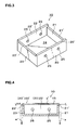
FIG. 3 is a perspective view of a vessel; and
FIG. 4 is an explanatory view showing the state when a wire moves under the liquid level of an abrasive liquid formed in an upper surface opening of the vessel.
DETAILED DESCRIPTION OF THE PREFERRED EMBODIMENT
A preferred embodiment of the present invention will be hereinafter explained with reference to the drawings. FIG. 1 is a front view of an essential part of a wire saw 1 according to the embodiment of the present invention. FIG. 2 is a cross sectional view taken along the A—A line in FIG. 1.
The wire saw 1 includes a pair of main rolls 11, 12 disposed on right and left sides of a vessel 10 to which an abrasive liquid a is supplied and a drive roll 13 disposed below the vessel 10. A wire 15 is would on these main rolls 11, 12 and the drive roll 13 several times so that the wire 15 repeatedly moves back and forth in accordance with the rotation of these main rolls 11, 12 and the drive roll 13. Incidentally, a metal wire having a wire diameter of, for example, 0.06 mm to 1.2 mm is usable as the wire 15. As examples of the wire 15 in practical use, a steel wire, a piano wire, a stainless steel wire and the like are usable, and these wires with surface treatment such as brass plating, copper plating or the like given thereon can be also used. A supply reel and a take-up reel which are not shown are disposed outside the main rolls 11, 12 and the drive roll 13 so that the wire 15 supplied from the supply reel moves back and forth while being wound on the main rolls 11, 12 and the drive roll 13 several times to be taken up by the take-up reel.
The wire 15 is wound on the main rolls 11, 12 and the drive roll 13 several times, and as is seen from FIG. 2, the width of the vessel 10 from a front side surface to a rear side surface is larger than the total width of the array of the wire 15 wound on the main rolls 11, 12. Thereby, a large number of the wires 15 move between the main roll 11 and the main roll 12 while being kept parallel to one another at predetermined regular intervals apart from one another. Incidentally, a guide groove or the like, though not shown, is formed on the circumferential surface of each of the main rolls 11, 12 when necessary, in order to keep this parallel state of the wires 15.
As shown in FIG. 3, the vessel 10 is so shaped that an upper surface thereof is open and four side surfaces 20, 21, 22, 23 and a bottom surface 24 thereof are closed. Supply ports 25 for supplying the abrasive liquid a therethrough are formed in the front and rear side surfaces 20, 22, and the abrasive liquid a continuously supplied into the vessel 10 from the supply ports 25 flows out from the upper surface opening of the vessel 10 continuously. In this case, an abrasive liquid which is prepared by dispersing one kind of or two kinds or more of abrasive grains of silicon carbide, alumina, and diamond in oil, or the like is used as the abrasive liquid a. Viscosity of the abrasive liquid a is, for example, 10 mPa·s to 1000 mPa·s.
In the shown example, upper ends 20′, 22′ of the front and rear side surfaces 20, 22 of the vessel 10 and upper ends 21′, 23′ of the right and left side surfaces of the vessel 10 are all horizontal, but the upper ends 20′, 22′ of the front and rear side surfaces 20, 22 are formed to be higher than the upper ends 21′, 23′ of the right and left side surfaces 21, 23. In other words, the upper ends 20′, 22′ of the front and rear side surfaces 20, 22 of the vessel 10 are formed in a higher position and the upper ends 21′, 23′ of the right and left side surfaces 21, 23 of the vessel 10 are formed in a lower position.
Thus, the upper ends 20′, 22′ of the front and rear side surfaces 20, 22 of the vessel 10 are formed in the higher position and the upper ends 21′, 23′ of the right and left side surfaces 21, 23 are formed in the lower position so that the abrasive liquid a supplied continuously into the vessel 10 from the supply ports 25 as described above flows out over the upper ends 21′, 23′ of the right and left side surfaces 21, 23 in the upper surface opening of the vessel 10 to flow down continuously to right and left outside areas of the vessel 10, as shown in FIG. 4. In this case, a liquid level a′ of the abrasive liquid a in the upper surface opening of the vessel 10 is higher than the upper ends 21′, 23′ of the right and left side surfaces 21, 23 of the vessel 10.
The aforesaid main rolls 11, 12 are both horizontal and disposed outside the right and left side surfaces 21, 23 of the vessel 10 to be parallel to each other, sandwiching the vessel 10. Upper end portions of the circumferential surfaces of these main rolls 11, 12 are positioned higher than the upper ends 21′, 23′ (lower position) of the right and left side surfaces 21, 23 and lower than the upper ends 20′, 22′ (higher position) of the front and rear side surfaces 20, 22 of the vessel 10. Thereby, the wires 15 which move between the main rolls 11, 12 while kept parallel to one another at the predetermined regular intervals apart from one another as described above are moved horizontally in a position higher than the upper ends 21′, 23′ (lower position) of the right and left side surfaces 21, 23 and lower than the upper ends 20′, 22′ (higher position) of the front and rear side surfaces 20, 22 of the vessel 10 in the upper surface opening of the vessel 10. Further, in this case, the wires 15 which move while kept parallel to one another are, as shown in FIG. 4, positioned lower than the liquid level a′ of the abrasive liquid a which is formed in the upper surface opening of the vessel 10 so that the wires 15 move under the liquid level a′ of the abrasive liquid a (in other words, the supply amount of the abrasive liquid a continuously supplied into the vessel 10 from the supply ports 25 is so adjusted that the wires 15 which are positioned higher than the upper ends 21′, 23′ (lower position) of the right and left side surfaces 21, 23 and lower than the upper ends 20′, 22′ (higher position) of the front and rear side surfaces 20, 22 are under the liquid level a′ of the abrasive liquid a).
Above the vessel 10, a work W is supported by a raising/lowering mechanism 30. For example, a magnetic material in the shape of a rectangular parallelepiped is an example of the work W This raising/lowering mechanism 30 is operated to lower the work W so that a lower surface side of the work W is pressed onto the wires 15 from the above which are hung between the main rolls 11, 12 in parallel to one another at regular spaced intervals.
In the wire saw 1 as structured above, the abrasive liquid a is supplied continuously into the vessel 10 from the supply ports 25, the abrasive liquid a is caused to flow out continuously over the upper ends 21′, 23′ of the right and left side surfaces 21, 23 in the upper surface opening of the vessel 10 to the right and left outside areas of the vessel 10. Then, the wires 15 hung between the main rolls 11, 12 in parallel to one another at the predetermined regular intervals are moved back and forth while positioned lower than the liquid level a′ of the abrasive liquid a which is formed in the upper surface opening of the vessel 10 (in other words, while the supply amount of the abrasive liquid a which is supplied continuously into the vessel 10 from the supply ports 25 is so adjusted that the wires 15 are under the liquid level a′ of the abrasive liquid a). Then, the work W is lowered by the operation of the raising/lowering mechanism 30 so that the lower surface side of the work W is pressed onto the wires 15 from the above which move between the main rolls 11, 12 while kept parallel to one another at the regular spaced intervals. Thereby, the work W can be cut into a large number of thins plates.
Therefore, according to the wire saw 1 in this embodiment, the work W is pressed onto the wires 15 moving under the liquid level a′ of the abrasive liquid a so that the cutting operation can be performed in the abrasive liquid a. Consequently, a sufficient amount of the abrasive liquid a can be interposed between cut portions of the work W and the wires 15 for a long time, which eliminates the breakage of the wires 15 due to the shortage of the abrasive liquid a, thereby making it possible to obtain thin pieces having cut surfaces in a good condition.
An example of the preferred embodiment of the present invention is explained above, but the present invention is not limited to the embodiment shown here. For example, it is also suitable that the abrasive liquid a flowing out of the vessel 10 is collected by a drain pan or the like and supplied again to the vessel 10 by an appropriate circulation circuit. In this case, by removing chips through the use of a magnet-type filter or the like before the abrasive liquid a is supplied again to the vessel 10, the cutting operation can be continued for a longer period. Incidentally, the magnet-type filter or the like is preferably cleaned periodically.
The wire saw according to the present invention is effective for use in cutting, for example, a sintered rare earth magnet alloy. Since the sintered rare earth magnet alloy is very hard, having hardness of Hv 500 to 1000, and moreover, has a texture in which hard magnetic crystal grains are dispersed in a grain boundary layer, the magnetic crystal grains get easily chipped, having a hard and fragile property. When a work made of such a sintered rare earth magnet alloy is cut, damage and abrasion of a blade edge is unavoidable in cutting the hard magnetic crystal grains using, for example, a peripheral cutting edge and also the crystal grains fall off. Therefore, the occurrence of cracks is easily caused. On the other hand, according to the present invention, the work is cut while the wires are pressed onto the work in the abrasive liquid whose flow is formed so that the abrasive liquid stably containing the abrasive grains can be interposed between the work and the wires, which makes it possible to obtain cut pieces having very smooth cut surfaces even when the work is the sintered rare earth magnet alloy having the hard and fragile property as described above.
EXAMPLE
A cutting test is conducted in such a manner that a work made of a plate-shaped sintered material which is 30 mm in length×8 mm in external size and which is made of a magnet alloy is cut using a steel wire (brass-plated on the surface thereof) which is 0.18 mm in wire diameter and an abrasive liquid made by dispersing silicon carbide abrasive grains in mineral oil, under the condition that slice thickness is 1.0 mm. The duration of approximately three hours is set for the cutting time, and the cutting operation is carried out with the temperature of the abrasive liquid in the vessel being cooled so as to maintain the temperature between 25° C. and 30° C. while the work is being cut. As a result, cut surfaces of obtained cut pieces are very smooth and neither a saw mark nor a chipped portion is found.
Meanwhile, in a comparison example, a cutting test is conducted in the same manner as in the above embodiment example except that the abrasive liquid is supplied using a nozzle having a dual-tube structure. As a result, the wire is broken during the cutting operation. Moreover, saw marks parallel to the moving direction of the wire are found on the surfaces of cut pieces before the wire is broken, and more saw marks are found in a work positioned distant from the supply nozzle.

Claims (5)

What is claimed is:
1. A wire saw, comprising:
a wire for cutting a work while being pressed onto the work and moving in an axial direction thereof; and
an abrasive liquid, which is made by dispersing abrasive grains in a dispersion medium, interposed between said work and said wire and,
wherein a flow of said abrasive liquid is formed, and said wire moves under a liquid level of said abrasive liquid whose flow is formed, and the work is cut by said wire while partially submerged in the abrasive liquid.
2. The wire saw according to claim 1,
wherein said abrasive liquid is continuously supplied to a vessel to cause said abrasive liquid to flow out of an upper surface opening of the vessel continuously, and said wire moves under the liquid level of said abrasive liquid which is flowing out.
3. The wire saw according to claim 2,
wherein a higher position and a lower position are provided on upper ends of side surfaces of the vessel and said abrasive liquid flows out at the lower position.
4. The wire saw according to claim 3, further comprising:
a pair of main rolls, which is disposed on both sides of the vessel, for guiding said wire to move horizontally in the upper surface opening of the vessel,
wherein said lower position is formed in a position lower than said wire moving between said main rolls, and upper ends of circumferential surfaces of said main rolls are positioned higher than said lower position and lower than said higher position.
5. A method of cutting a work, comprising the step of:
moving a wire in an axial direction thereof to cut a work while pressing the wire onto the work and interposing an abrasive liquid, which is made by dispersing abrasive grains in a dispersion medium, between the work and the wire,
wherein a flow of the abrasive liquid is formed, and the wire is pressed onto the work while moving under a liquid level of the abrasive liquid whose flow is formed, and the work is cut by said wire while partially submerged in the abrasive liquid.
US10/279,723 2001-11-30 2002-10-25 Wire saw and cutting method thereof Expired - Fee Related US6832606B2 (en)

Applications Claiming Priority (3)

Application Number Priority Date Filing Date Title
JPJP2001-366517 2001-11-11
JP2001-366517 2001-11-30
JP2001366517 2001-11-30

Publications (2)

Publication Number Publication Date
US20030089362A1 US20030089362A1 (en) 2003-05-15
US6832606B2 true US6832606B2 (en) 2004-12-21

Family

ID=19176402

Family Applications (1)

Application Number Title Priority Date Filing Date
US10/279,723 Expired - Fee Related US6832606B2 (en) 2001-11-30 2002-10-25 Wire saw and cutting method thereof

Country Status (1)

Country Link
US (1) US6832606B2 (en)

Cited By (9)

* Cited by examiner, † Cited by third party
Publication number Priority date Publication date Assignee Title
US20040159316A1 (en) * 2003-01-13 2004-08-19 Andreas Muller Wire sawing device
US20060249134A1 (en) * 2003-10-27 2006-11-09 Takafumi Kawasaki Multi-wire saw
US20080149085A1 (en) * 2006-12-20 2008-06-26 Siltronic Ag Method and Device For Sawing A Workpiece
US20110174285A1 (en) * 2008-11-07 2011-07-21 Shin-Etsu Handotai Co., Ltd. Ingot cutting apparatus and ingot cutting method
US20120167733A1 (en) * 2010-12-31 2012-07-05 Cheng Ming Lee Cooling Device for Diamond-Wire Cutting System
US20120255535A1 (en) * 2011-04-05 2012-10-11 Siltronic Ag Method for cutting workpiece with wire saw
US20130081606A1 (en) * 2010-09-29 2013-04-04 Yang-Suh Kim Sawing apparatus of single crystal ingot
US20160025647A1 (en) * 2009-12-08 2016-01-28 Allison Transmission, Inc. Method for detecting and/or preventing grind burn
US9776264B2 (en) 2014-03-05 2017-10-03 Mike Shaw Reciprocating cutter

Families Citing this family (7)

* Cited by examiner, † Cited by third party
Publication number Priority date Publication date Assignee Title
KR101548147B1 (en) 2009-08-14 2015-08-28 생-고뱅 어브레이시브즈, 인코포레이티드 Abrasive articles including abrasive particles bonded to an elongated body
TWI483803B (en) * 2012-06-29 2015-05-11 Saint Gobain Abrasives Inc Method of conducting a cutting operation on a workpiece
TW201404527A (en) 2012-06-29 2014-02-01 Saint Gobain Abrasives Inc Abrasive article and method of forming
JP2016203321A (en) * 2015-04-24 2016-12-08 株式会社安永 Wire saw, and manufacturing method of manufacturing plurality of sliced articles from workpiece using wire saw
TWI621505B (en) 2015-06-29 2018-04-21 聖高拜磨料有限公司 Abrasive article and method of forming
CN106976167A (en) * 2017-03-17 2017-07-25 浙江好亚能源股份有限公司 Diamond cutting line slicing machine
CN107030904A (en) * 2017-05-11 2017-08-11 济源石晶光电频率技术有限公司 Crystalline substance stone roller cutting method

Citations (5)

* Cited by examiner, † Cited by third party
Publication number Priority date Publication date Assignee Title
US5827113A (en) 1995-09-22 1998-10-27 Memc Electric Materials, Inc. Cutting machine
US6390896B1 (en) * 1998-09-10 2002-05-21 WACKER SILTRONIC GESELLSCHAFT FüR HALBLEITERMATERIALIEN AG Method and device for cutting a multiplicity of disks from a hard brittle workpiece
US6408840B2 (en) * 1999-12-14 2002-06-25 Sumitomo Special Metals Co., Ltd. Method and apparatus for cutting a rare earth alloy
US6422067B1 (en) * 1999-04-26 2002-07-23 Super Silicon Crystal Research Institute Corporation Slurry useful for wire-saw slicing and evaluation of slurry
US6505394B2 (en) * 1998-09-01 2003-01-14 Sumitomo Special Metals Co., Ltd. Method for cutting rare earth alloy, method for manufacturing rare earth alloy plates and method for manufacturing rare earth alloy magnets using wire saw, and voice coil motor

Patent Citations (5)

* Cited by examiner, † Cited by third party
Publication number Priority date Publication date Assignee Title
US5827113A (en) 1995-09-22 1998-10-27 Memc Electric Materials, Inc. Cutting machine
US6505394B2 (en) * 1998-09-01 2003-01-14 Sumitomo Special Metals Co., Ltd. Method for cutting rare earth alloy, method for manufacturing rare earth alloy plates and method for manufacturing rare earth alloy magnets using wire saw, and voice coil motor
US6390896B1 (en) * 1998-09-10 2002-05-21 WACKER SILTRONIC GESELLSCHAFT FüR HALBLEITERMATERIALIEN AG Method and device for cutting a multiplicity of disks from a hard brittle workpiece
US6422067B1 (en) * 1999-04-26 2002-07-23 Super Silicon Crystal Research Institute Corporation Slurry useful for wire-saw slicing and evaluation of slurry
US6408840B2 (en) * 1999-12-14 2002-06-25 Sumitomo Special Metals Co., Ltd. Method and apparatus for cutting a rare earth alloy

Non-Patent Citations (2)

* Cited by examiner, † Cited by third party
Title
Office Action issued by the Patent Office of the People's Republic of China issued Mar. 5, 2004 in connection with corresponding application filed in China.
Republic of China Office Action, dated Mar. 5, 2004.

Cited By (16)

* Cited by examiner, † Cited by third party
Publication number Priority date Publication date Assignee Title
US20040159316A1 (en) * 2003-01-13 2004-08-19 Andreas Muller Wire sawing device
US7114424B2 (en) * 2003-01-13 2006-10-03 Hct Shaping Systems S.A. Wire sawing device
US20060249134A1 (en) * 2003-10-27 2006-11-09 Takafumi Kawasaki Multi-wire saw
US7306508B2 (en) * 2003-10-27 2007-12-11 Mitsubishi Denki Kabushiki Kaisha Multi-wire saw
US20080149085A1 (en) * 2006-12-20 2008-06-26 Siltronic Ag Method and Device For Sawing A Workpiece
US7793647B2 (en) * 2006-12-20 2010-09-14 Siltronic Ag Method and device for sawing a workpiece
US20110174285A1 (en) * 2008-11-07 2011-07-21 Shin-Etsu Handotai Co., Ltd. Ingot cutting apparatus and ingot cutting method
US9314942B2 (en) * 2008-11-07 2016-04-19 Shin-Etsu Handotai Co., Ltd. Ingot cutting apparatus and ingot cutting method
US20160025647A1 (en) * 2009-12-08 2016-01-28 Allison Transmission, Inc. Method for detecting and/or preventing grind burn
US10213898B2 (en) * 2009-12-08 2019-02-26 Allison Transmission, Inc. Method for detecting and/or preventing grind burn
US20130081606A1 (en) * 2010-09-29 2013-04-04 Yang-Suh Kim Sawing apparatus of single crystal ingot
US8752537B2 (en) * 2010-09-29 2014-06-17 Lg Siltron Inc. Sawing apparatus of single crystal ingot
US20120167733A1 (en) * 2010-12-31 2012-07-05 Cheng Ming Lee Cooling Device for Diamond-Wire Cutting System
US9073235B2 (en) * 2011-04-05 2015-07-07 Siltronic Ag Method for cutting workpiece with wire saw
US20120255535A1 (en) * 2011-04-05 2012-10-11 Siltronic Ag Method for cutting workpiece with wire saw
US9776264B2 (en) 2014-03-05 2017-10-03 Mike Shaw Reciprocating cutter

Also Published As

Publication number Publication date
US20030089362A1 (en) 2003-05-15

Similar Documents

Publication Publication Date Title
US6832606B2 (en) Wire saw and cutting method thereof
TWI405254B (en) Production method of group III nitride substrate
US6443143B1 (en) Method and apparatus for cutting rare earth alloy
JP5515593B2 (en) Method for cutting silicon ingot with wire saw and wire saw
KR20000023015A (en) Method and device for cutting a multiplicity of disks off a hard brittle workpiece
CN1157277C (en) Cut off method of rare earth alloy and cut off device
JP5458128B2 (en) Method for simultaneously cutting at least two cylindrical workpieces into multiple wafers
KR20000022567A (en) Method for cutting rare earth alloy, method for manufacturing rare earth alloy plates and method for manufacturing rare earth alloy magnets using wire saw, and voice coil motor
JP2011526215A (en) Wire saw cutting equipment
CN1219628C (en) Scroll saw and its cutting method
JP2010194706A (en) Method of manufacturing substrate
JP2000218504A (en) Wire with fixed abrasive grains and cutting method for fixed abrasive grains wire saw
JP5003696B2 (en) Group III nitride substrate and manufacturing method thereof
US11717930B2 (en) Method for simultaneously cutting a plurality of disks from a workpiece
JP2000288903A (en) Surface grinding method and surface grinding device using multiwire saw
JP5876388B2 (en) Workpiece cutting method
JP3695124B2 (en) Wire saw equipment
JP5355249B2 (en) Wire saw equipment
JP5527987B2 (en) Wire saw device and substrate manufacturing method
JP2016101611A (en) Manufacturing method of substrate
JP3967969B2 (en) Wire saw
JP2005153035A (en) Wire saw device
KR101487986B1 (en) A wire saw
JP2003326450A (en) Pulley for wire saw and wire saw using it
JP4377674B2 (en) Semiconductor substrate forming apparatus

Legal Events

Date Code Title Description
AS Assignment

Owner name: DOWA MINING CO., LTD., JAPAN

Free format text: ASSIGNMENT OF ASSIGNORS INTEREST;ASSIGNORS:YAMADA, KIYOSHI;OTAKE, NOBUO;TAKEI, HIROFUMI;REEL/FRAME:013444/0338

Effective date: 20020826

FPAY Fee payment

Year of fee payment: 4

FPAY Fee payment

Year of fee payment: 8

FEPP Fee payment procedure

Free format text: PAYOR NUMBER ASSIGNED (ORIGINAL EVENT CODE: ASPN); ENTITY STATUS OF PATENT OWNER: LARGE ENTITY

REMI Maintenance fee reminder mailed
LAPS Lapse for failure to pay maintenance fees
STCH Information on status: patent discontinuation

Free format text: PATENT EXPIRED DUE TO NONPAYMENT OF MAINTENANCE FEES UNDER 37 CFR 1.362

FP Lapsed due to failure to pay maintenance fee

Effective date: 20161221