US6831704B1 - Linking external devices to switcher transitions - Google Patents
Linking external devices to switcher transitions Download PDFInfo
- Publication number
- US6831704B1 US6831704B1 US09/365,282 US36528299A US6831704B1 US 6831704 B1 US6831704 B1 US 6831704B1 US 36528299 A US36528299 A US 36528299A US 6831704 B1 US6831704 B1 US 6831704B1
- Authority
- US
- United States
- Prior art keywords
- transition
- external device
- trigger
- video
- activated
- Prior art date
- Legal status (The legal status is an assumption and is not a legal conclusion. Google has not performed a legal analysis and makes no representation as to the accuracy of the status listed.)
- Expired - Lifetime
Links
Images

Classifications
-
- H—ELECTRICITY
- H04—ELECTRIC COMMUNICATION TECHNIQUE
- H04N—PICTORIAL COMMUNICATION, e.g. TELEVISION
- H04N5/00—Details of television systems
- H04N5/222—Studio circuitry; Studio devices; Studio equipment
- H04N5/262—Studio circuits, e.g. for mixing, switching-over, change of character of image, other special effects ; Cameras specially adapted for the electronic generation of special effects
- H04N5/265—Mixing
-
- H—ELECTRICITY
- H04—ELECTRIC COMMUNICATION TECHNIQUE
- H04N—PICTORIAL COMMUNICATION, e.g. TELEVISION
- H04N5/00—Details of television systems
- H04N5/222—Studio circuitry; Studio devices; Studio equipment
- H04N5/262—Studio circuits, e.g. for mixing, switching-over, change of character of image, other special effects ; Cameras specially adapted for the electronic generation of special effects
- H04N5/268—Signal distribution or switching
Definitions
- the present invention relates to video signal processing, and more particularly to linking external devices to switcher transitions so that an operator may treat transitions which include sound effects or animations in the same way as a simple mix or wipe.
- Video production switchers have become the center of a live production system, not only for video but also for device control. Modern effects involve many devices that have to be driven in synchronism. Such modern effects may involve sound effects or playback of short animations synchronized with a switcher mix, wipe or digital effect fly-in. Presently production switchers provide this capability through an effects memory system. However it is difficult to manage such effects for real world situations. Effects programmed to involve a background video signal and a key signal, for example, would have to be rebuilt in order to apply only to the background video signal. Operators focus on the switcher's transition system for making changes in the program content, but must change their thinking process when the transition involves external devices, such as sound effects, animations or digital effects fly-in.
- the present invention provides a method of linking external devices to a video production switcher so that transitions that involve sound effects, animations or digital effects fly-ins may be treated as simple mixes or wipes.
- a “Trigger” function is added as a transition element. During preconfiguration of an effect in an effects memory, the trigger is set, the external device indicated and a trigger value established. When the effect is recalled for activation and a trigger enable control is activated at a transition control panel, the external device is activated during the transition at a point determined by the trigger value.
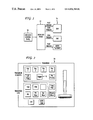
- FIG. 1 is a block diagram view of a switcher system for linking external devices to switcher transitions according to the present invention.
- FIG. 2 is a plan view of a transition control panel for a switcher that links external devices to switcher transitions according to the present invention.
- FIG. 3 is an illustrative view of the waveforms and actions associated with linking external devices to switcher transitions according to the present invention.
- a switcher system having a switcher frame 12 that processes video signals and generates trigger control signals for a plurality of external devices 14 , such as a digital disk recorder (DDR), a digital video effects (DVE) device, an audio playback device and the like.
- DDR digital disk recorder
- DVE digital video effects
- An operator enters control commands for the switcher frame 12 via a switcher control panel 16 .
- a transition occurs as a ramp between two signals, with one signal gradually changing to the other signal during a time interval T.
- the transition may end with the second signal on the screen, or at the end of time T the signals may flip-flop so that the first signal is returned to the screen at the end of the transition, such as when the preview and program buses are switched at the end of the transition.
- the next two timelines show the key signal transitions when transitioning from keyer 1 to keyer 2 outputs.
- one or more of the external devices is activated on the timeline T in sync with the progress of the transition, such as when the trigger value is set to 0%, or triggered at a user-defined point in the transition depending upon the trigger level set. What the external device does in response to this stimulus is determined by the external device. This may be to jog or trigger playback of a video and/or audio clip.
- a transition effect may be preconfigured to have a trigger element with a trigger value of 0% to start a DDR playback and a trigger value of 100% to stop the DDR playback.
- the trigger enable control 18 is activated the DDR output will play during the transition interval T.
- the trigger value is set at 25% for a DVE, which results in the DVE effect occurring 25% into the transition interval.
- an audio example is presented where the trigger value is set at 50% so that the sound effect from the audio playback occurs at the midpoint of the transition interval.
- the trigger element is set and values defined together with the associated external device during preconfiguration when the various effects are stored in the effects memory for a particular mix/effects bank.
- the values may be anything between 0% and 100%.
- the trigger values are loaded into an effects register when an effect is recalled which has a trigger element preconfigured as part of the effect.
- the transition effect may then be activated, either manually via a lever arm or automatically.
- the external device is not activated unless the trigger enable control 18 on the control panel 16 has been activated. This allows preview of an effect without the external device 14 . However when played to air the trigger enable control 18 is activated to play the full effect.
- Each trigger element could be one of the following: a GPI (general purpose relay interface) closure; a peripheral bus serial interface command; a VTR or DVE serial protocol command; a musical instrument digital interface (MIDI) command; or a facility manager command.
- GPI general purpose relay interface
- MIDI musical instrument digital interface
- the present invention provides a method of linking external devices to video production switcher transitions using an additional trigger transition element for controlling such external devices so that transitions that include sound effects, animations or digital effects fly-ins are treated as simple mixes or wipes.
Abstract
Description
Claims (8)
Priority Applications (1)
| Application Number | Priority Date | Filing Date | Title |
|---|---|---|---|
| US09/365,282 US6831704B1 (en) | 1999-07-30 | 1999-07-30 | Linking external devices to switcher transitions |
Applications Claiming Priority (1)
| Application Number | Priority Date | Filing Date | Title |
|---|---|---|---|
| US09/365,282 US6831704B1 (en) | 1999-07-30 | 1999-07-30 | Linking external devices to switcher transitions |
Publications (1)
| Publication Number | Publication Date |
|---|---|
| US6831704B1 true US6831704B1 (en) | 2004-12-14 |
Family
ID=33489200
Family Applications (1)
| Application Number | Title | Priority Date | Filing Date |
|---|---|---|---|
| US09/365,282 Expired - Lifetime US6831704B1 (en) | 1999-07-30 | 1999-07-30 | Linking external devices to switcher transitions |
Country Status (1)
| Country | Link |
|---|---|
| US (1) | US6831704B1 (en) |
Cited By (2)
| Publication number | Priority date | Publication date | Assignee | Title |
|---|---|---|---|---|
| EP2088770A1 (en) | 2008-02-06 | 2009-08-12 | Thomson Licensing | Video production switcher and method of operation |
| US20100182508A1 (en) * | 2007-08-30 | 2010-07-22 | Thomson Licensing | auxiliary bus transitions on a video switcher |
Citations (31)
| Publication number | Priority date | Publication date | Assignee | Title |
|---|---|---|---|---|
| US3944731A (en) * | 1975-03-03 | 1976-03-16 | Sarkes Tarzian, Inc. | Video special effects generator |
| US4218709A (en) * | 1977-10-05 | 1980-08-19 | Echolabs, Inc. | Video switching system |
| US4532547A (en) * | 1982-03-31 | 1985-07-30 | Ampex Corporation | Video device synchronization system |
| US4581645A (en) * | 1983-06-28 | 1986-04-08 | Rca Corporation | Distributed switched component audio/video system |
| US4644400A (en) * | 1984-04-09 | 1987-02-17 | Nec Corporation | Digital audio synchronizing system with cross-fade means |
| US4668999A (en) * | 1984-12-04 | 1987-05-26 | Cierva Sr Juan De | Time base equalizer and corrector (TIBEC) for video tape or disk machines in playback modes |
| US4808992A (en) * | 1987-05-08 | 1989-02-28 | Rca Licensing Corporation | Component audio/video system with automatic turn-off of peripheral devices |
| US4855834A (en) * | 1987-11-21 | 1989-08-08 | Quantel Limited | Video wipe processing apparatus |
| US5109280A (en) * | 1985-11-15 | 1992-04-28 | Karlock James A | Video switcher/effects generator |
| US5162904A (en) * | 1991-03-28 | 1992-11-10 | Abekas Video Systems, Inc. | Video processing system having improved internal switching capability |
| US5189563A (en) * | 1990-12-14 | 1993-02-23 | Sima Products Corporation | Video tape editor with fade control functions |
| US5287186A (en) * | 1991-08-30 | 1994-02-15 | Sony Corporation | Video switcher apparatus with back-up system |
| US5396636A (en) * | 1991-10-21 | 1995-03-07 | International Business Machines Corporation | Remote power control via data link |
| US5532830A (en) * | 1982-12-22 | 1996-07-02 | Lex Computer And Management Corporation | Routing apparatus and method for video composition |
| US5563579A (en) * | 1992-02-04 | 1996-10-08 | Carter; Ronald L. | Dealer information and security apparatus and method |
| US5657221A (en) * | 1994-09-16 | 1997-08-12 | Medialink Technologies Corporation | Method and apparatus for controlling non-computer system devices by manipulating a graphical representation |
| US5786864A (en) * | 1992-11-05 | 1998-07-28 | Canon Kabushiki Kaisha | Moving picture processing apparatus and method wherein image data and special effects data are transmitted in common |
| US5903702A (en) * | 1994-08-30 | 1999-05-11 | Sony Corporation | Apparatus and method for editing isochronous information transmitted among various devices |
| US5982350A (en) * | 1991-10-07 | 1999-11-09 | Eastman Kodak Company | Compositer interface for arranging the components of special effects for a motion picture production |
| US6023675A (en) * | 1993-03-24 | 2000-02-08 | Engate Incorporated | Audio and video transcription system for manipulating real-time testimony |
| US6144798A (en) * | 1994-04-11 | 2000-11-07 | Sony Corporation | Method of and apparatus for editing information recorded on magnetic tape |
| US6191814B1 (en) * | 1997-02-21 | 2001-02-20 | Elbex Video Ltd. | Apparatus for powering television cameras via camera transmission lines |
| US6204840B1 (en) * | 1997-04-08 | 2001-03-20 | Mgi Software Corporation | Non-timeline, non-linear digital multimedia composition method and system |
| US6259488B1 (en) * | 1999-07-22 | 2001-07-10 | Grass Valley (Us) Inc. | Concealing temporal shift when using a digital video effect system with a video switcher |
| US6271829B1 (en) * | 1994-03-18 | 2001-08-07 | Avid Technology, Inc. | Editing interface |
| US6285406B1 (en) * | 1997-03-28 | 2001-09-04 | Compaq Computer Corporation | Power management schemes for apparatus with converged functionalities |
| US6438618B1 (en) * | 1998-12-16 | 2002-08-20 | Intel Corporation | Method and device for filtering events in an event notification service |
| US6452612B1 (en) * | 1998-12-18 | 2002-09-17 | Parkervision, Inc. | Real time video production system and method |
| US6524169B1 (en) * | 1998-12-09 | 2003-02-25 | Sandvik Ab | Method for manufacture of tubes of a zirconium-based alloy |
| US6678002B2 (en) * | 1998-04-03 | 2004-01-13 | Avid Technology, Inc. | HDTV editing and effects previsualization using SDTV devices |
| US6686970B1 (en) * | 1997-10-03 | 2004-02-03 | Canon Kabushiki Kaisha | Multi-media editing method and apparatus |
-
1999
- 1999-07-30 US US09/365,282 patent/US6831704B1/en not_active Expired - Lifetime
Patent Citations (31)
| Publication number | Priority date | Publication date | Assignee | Title |
|---|---|---|---|---|
| US3944731A (en) * | 1975-03-03 | 1976-03-16 | Sarkes Tarzian, Inc. | Video special effects generator |
| US4218709A (en) * | 1977-10-05 | 1980-08-19 | Echolabs, Inc. | Video switching system |
| US4532547A (en) * | 1982-03-31 | 1985-07-30 | Ampex Corporation | Video device synchronization system |
| US5532830A (en) * | 1982-12-22 | 1996-07-02 | Lex Computer And Management Corporation | Routing apparatus and method for video composition |
| US4581645A (en) * | 1983-06-28 | 1986-04-08 | Rca Corporation | Distributed switched component audio/video system |
| US4644400A (en) * | 1984-04-09 | 1987-02-17 | Nec Corporation | Digital audio synchronizing system with cross-fade means |
| US4668999A (en) * | 1984-12-04 | 1987-05-26 | Cierva Sr Juan De | Time base equalizer and corrector (TIBEC) for video tape or disk machines in playback modes |
| US5109280A (en) * | 1985-11-15 | 1992-04-28 | Karlock James A | Video switcher/effects generator |
| US4808992A (en) * | 1987-05-08 | 1989-02-28 | Rca Licensing Corporation | Component audio/video system with automatic turn-off of peripheral devices |
| US4855834A (en) * | 1987-11-21 | 1989-08-08 | Quantel Limited | Video wipe processing apparatus |
| US5189563A (en) * | 1990-12-14 | 1993-02-23 | Sima Products Corporation | Video tape editor with fade control functions |
| US5162904A (en) * | 1991-03-28 | 1992-11-10 | Abekas Video Systems, Inc. | Video processing system having improved internal switching capability |
| US5287186A (en) * | 1991-08-30 | 1994-02-15 | Sony Corporation | Video switcher apparatus with back-up system |
| US5982350A (en) * | 1991-10-07 | 1999-11-09 | Eastman Kodak Company | Compositer interface for arranging the components of special effects for a motion picture production |
| US5396636A (en) * | 1991-10-21 | 1995-03-07 | International Business Machines Corporation | Remote power control via data link |
| US5563579A (en) * | 1992-02-04 | 1996-10-08 | Carter; Ronald L. | Dealer information and security apparatus and method |
| US5786864A (en) * | 1992-11-05 | 1998-07-28 | Canon Kabushiki Kaisha | Moving picture processing apparatus and method wherein image data and special effects data are transmitted in common |
| US6023675A (en) * | 1993-03-24 | 2000-02-08 | Engate Incorporated | Audio and video transcription system for manipulating real-time testimony |
| US6271829B1 (en) * | 1994-03-18 | 2001-08-07 | Avid Technology, Inc. | Editing interface |
| US6144798A (en) * | 1994-04-11 | 2000-11-07 | Sony Corporation | Method of and apparatus for editing information recorded on magnetic tape |
| US5903702A (en) * | 1994-08-30 | 1999-05-11 | Sony Corporation | Apparatus and method for editing isochronous information transmitted among various devices |
| US5657221A (en) * | 1994-09-16 | 1997-08-12 | Medialink Technologies Corporation | Method and apparatus for controlling non-computer system devices by manipulating a graphical representation |
| US6191814B1 (en) * | 1997-02-21 | 2001-02-20 | Elbex Video Ltd. | Apparatus for powering television cameras via camera transmission lines |
| US6285406B1 (en) * | 1997-03-28 | 2001-09-04 | Compaq Computer Corporation | Power management schemes for apparatus with converged functionalities |
| US6204840B1 (en) * | 1997-04-08 | 2001-03-20 | Mgi Software Corporation | Non-timeline, non-linear digital multimedia composition method and system |
| US6686970B1 (en) * | 1997-10-03 | 2004-02-03 | Canon Kabushiki Kaisha | Multi-media editing method and apparatus |
| US6678002B2 (en) * | 1998-04-03 | 2004-01-13 | Avid Technology, Inc. | HDTV editing and effects previsualization using SDTV devices |
| US6524169B1 (en) * | 1998-12-09 | 2003-02-25 | Sandvik Ab | Method for manufacture of tubes of a zirconium-based alloy |
| US6438618B1 (en) * | 1998-12-16 | 2002-08-20 | Intel Corporation | Method and device for filtering events in an event notification service |
| US6452612B1 (en) * | 1998-12-18 | 2002-09-17 | Parkervision, Inc. | Real time video production system and method |
| US6259488B1 (en) * | 1999-07-22 | 2001-07-10 | Grass Valley (Us) Inc. | Concealing temporal shift when using a digital video effect system with a video switcher |
Non-Patent Citations (2)
| Title |
|---|
| (WO 92/22983) Browne, Large capacity, random access, multi-source recorder player, Dec. 23, 1992, PCT. * |
| Browne et al, Large capacity, random access, mult-source recorder player, Dec. 23, 1992.* * |
Cited By (3)
| Publication number | Priority date | Publication date | Assignee | Title |
|---|---|---|---|---|
| US20100182508A1 (en) * | 2007-08-30 | 2010-07-22 | Thomson Licensing | auxiliary bus transitions on a video switcher |
| US8605220B2 (en) * | 2007-08-30 | 2013-12-10 | Gvbb Holdings S.A.R.L. | Generation of video transitions on an auxiliary bus using a video switcher |
| EP2088770A1 (en) | 2008-02-06 | 2009-08-12 | Thomson Licensing | Video production switcher and method of operation |
Similar Documents
| Publication | Publication Date | Title |
|---|---|---|
| CA2553481C (en) | Television production technique | |
| DE69633540T2 (en) | Information recording device and information reproducing device | |
| JPH10285527A (en) | Video processing system, device and method | |
| US6831704B1 (en) | Linking external devices to switcher transitions | |
| CA2553603C (en) | Television production technique | |
| JPH02196579A (en) | Multifunction video head selecting device and its method | |
| JP3277423B2 (en) | Video editing method | |
| JP2005278212A (en) | Image editing method and image editing system | |
| JP2968169B2 (en) | Multimedia information processing device | |
| US20020076197A1 (en) | AV data recording/reproducing apparatus, AV data recording/reproducing method, and recording medium | |
| JP2000013737A (en) | Edition device, its method and providing medium | |
| JPH0676545A (en) | Background music playing device | |
| JPH0721682A (en) | Controller for mixing console device | |
| JP4213287B2 (en) | Schedule reproduction apparatus and recording medium | |
| JP2662056B2 (en) | Signal recording / reproducing device | |
| KR0136417B1 (en) | Recording/reproducing apparatus and method having function of title editing | |
| JP2586448B2 (en) | Digital signal recording / reproducing device | |
| JPS5997283A (en) | Control circuit of magnetic recorder and reproducer | |
| JP2000069360A (en) | Edition device and its method | |
| JP2850324B2 (en) | Magnetic recording / reproducing device | |
| JPH0282777A (en) | Picture reproducing device | |
| KR20020090022A (en) | Programable combination system | |
| JPH05205444A (en) | Editing device | |
| JPH05205446A (en) | Editing device | |
| JPH06139330A (en) | Picture generating device |
Legal Events
| Date | Code | Title | Description |
|---|---|---|---|
| AS | Assignment |
Owner name: GRASS VALLEY (US) INC., CALIFORNIA Free format text: ASSIGNMENT OF ASSIGNORS INTEREST;ASSIGNOR:TEKTRONIX, INC.;REEL/FRAME:010280/0369 Effective date: 19990924 Owner name: CONGRESS FINANCIAL CORPORATION (WESTERN), OREGON Free format text: SECURITY AGREEMENT;ASSIGNOR:GRASS VALLEY (US) INC.;REEL/FRAME:010415/0156 Effective date: 19990924 |
|
| AS | Assignment |
Owner name: TEKTRONIX, INC., AN OREGON CORPORATION, OREGON Free format text: SECURITY INTEREST;ASSIGNOR:GRASS VALLEY GROUP INC.;REEL/FRAME:010288/0161 Effective date: 19990924 |
|
| STCF | Information on status: patent grant |
Free format text: PATENTED CASE |
|
| FPAY | Fee payment |
Year of fee payment: 4 |
|
| AS | Assignment |
Owner name: THOMSON LICENSING, FRANCE Free format text: RELEASE OF SECURITY INTEREST;ASSIGNOR:WACHOVIA BANK N.A. (SUCCESSOR IN INTEREST TO CONGRESS FINANCIAL CORPORATION);REEL/FRAME:022678/0056 Effective date: 20090421 Owner name: GRASS VALLEY (U.S.) INC., CALIFORNIA Free format text: RELEASE OF SECURITY INTEREST;ASSIGNOR:WACHOVIA BANK N.A. (SUCCESSOR IN INTEREST TO CONGRESS FINANCIAL CORPORATION);REEL/FRAME:022678/0056 Effective date: 20090421 |
|
| AS | Assignment |
Owner name: GRASS VALLEY (U.S.) INC., CALIFORNIA Free format text: RELEASE OF SECURITY INTEREST;ASSIGNOR:TEKTRONIX, INC.;REEL/FRAME:022714/0574 Effective date: 20090420 Owner name: THOMSON LICENSING, FRANCE Free format text: RELEASE OF SECURITY INTEREST;ASSIGNOR:TEKTRONIX, INC.;REEL/FRAME:022714/0574 Effective date: 20090420 |
|
| FPAY | Fee payment |
Year of fee payment: 8 |
|
| FPAY | Fee payment |
Year of fee payment: 12 |