US6830679B2 - Filtration device - Google Patents
Filtration device Download PDFInfo
- Publication number
- US6830679B2 US6830679B2 US10/284,457 US28445702A US6830679B2 US 6830679 B2 US6830679 B2 US 6830679B2 US 28445702 A US28445702 A US 28445702A US 6830679 B2 US6830679 B2 US 6830679B2
- Authority
- US
- United States
- Prior art keywords
- filter
- filtration
- pipe
- tank
- fluid
- Prior art date
- Legal status (The legal status is an assumption and is not a legal conclusion. Google has not performed a legal analysis and makes no representation as to the accuracy of the status listed.)
- Expired - Fee Related
Links
- 238000001914 filtration Methods 0.000 title claims abstract description 317
- 108010025899 gelatin film Proteins 0.000 claims abstract description 94
- 238000000034 method Methods 0.000 claims abstract description 78
- 230000008569 process Effects 0.000 claims abstract description 52
- 239000011859 microparticle Substances 0.000 claims abstract description 38
- XLYOFNOQVPJJNP-UHFFFAOYSA-N water Substances O XLYOFNOQVPJJNP-UHFFFAOYSA-N 0.000 claims description 123
- 239000012530 fluid Substances 0.000 claims description 80
- 230000003287 optical effect Effects 0.000 claims description 34
- 238000011069 regeneration method Methods 0.000 claims description 32
- 230000008929 regeneration Effects 0.000 claims description 30
- 230000015572 biosynthetic process Effects 0.000 claims description 19
- 238000002834 transmittance Methods 0.000 claims description 14
- 238000005273 aeration Methods 0.000 claims description 13
- 239000007788 liquid Substances 0.000 claims description 13
- 230000002706 hydrostatic effect Effects 0.000 claims description 8
- 238000011110 re-filtration Methods 0.000 claims description 8
- 230000007423 decrease Effects 0.000 claims description 6
- 238000012546 transfer Methods 0.000 claims description 4
- 239000002351 wastewater Substances 0.000 abstract description 92
- 239000002002 slurry Substances 0.000 description 35
- 239000000243 solution Substances 0.000 description 34
- 235000012431 wafers Nutrition 0.000 description 30
- VYPSYNLAJGMNEJ-UHFFFAOYSA-N Silicium dioxide Chemical compound O=[Si]=O VYPSYNLAJGMNEJ-UHFFFAOYSA-N 0.000 description 29
- 239000006061 abrasive grain Substances 0.000 description 25
- 239000011148 porous material Substances 0.000 description 20
- 239000004065 semiconductor Substances 0.000 description 18
- 239000000499 gel Substances 0.000 description 17
- 239000000126 substance Substances 0.000 description 17
- 239000002699 waste material Substances 0.000 description 17
- 239000002245 particle Substances 0.000 description 16
- 238000000227 grinding Methods 0.000 description 13
- 239000000377 silicon dioxide Substances 0.000 description 12
- 125000006850 spacer group Chemical group 0.000 description 12
- 239000008213 purified water Substances 0.000 description 11
- 238000005299 abrasion Methods 0.000 description 10
- 238000009499 grossing Methods 0.000 description 10
- 230000007246 mechanism Effects 0.000 description 10
- 230000008961 swelling Effects 0.000 description 10
- 238000005498 polishing Methods 0.000 description 9
- 238000000926 separation method Methods 0.000 description 8
- 239000012085 test solution Substances 0.000 description 8
- 238000004062 sedimentation Methods 0.000 description 7
- PNEYBMLMFCGWSK-UHFFFAOYSA-N aluminium oxide Inorganic materials [O-2].[O-2].[O-2].[Al+3].[Al+3] PNEYBMLMFCGWSK-UHFFFAOYSA-N 0.000 description 6
- 239000004744 fabric Substances 0.000 description 6
- 238000004064 recycling Methods 0.000 description 6
- 239000003082 abrasive agent Substances 0.000 description 5
- 238000013459 approach Methods 0.000 description 5
- 239000000919 ceramic Substances 0.000 description 5
- 230000001112 coagulating effect Effects 0.000 description 5
- 239000002440 industrial waste Substances 0.000 description 5
- 239000011229 interlayer Substances 0.000 description 5
- 239000000463 material Substances 0.000 description 5
- 229910052751 metal Inorganic materials 0.000 description 5
- 239000002184 metal Substances 0.000 description 5
- 238000002156 mixing Methods 0.000 description 5
- 239000012466 permeate Substances 0.000 description 5
- 238000001556 precipitation Methods 0.000 description 5
- 229910052710 silicon Inorganic materials 0.000 description 5
- MCMNRKCIXSYSNV-UHFFFAOYSA-N Zirconium dioxide Chemical compound O=[Zr]=O MCMNRKCIXSYSNV-UHFFFAOYSA-N 0.000 description 4
- 230000008901 benefit Effects 0.000 description 4
- 239000000701 coagulant Substances 0.000 description 4
- 238000001514 detection method Methods 0.000 description 4
- 238000010790 dilution Methods 0.000 description 4
- 239000012895 dilution Substances 0.000 description 4
- 238000009826 distribution Methods 0.000 description 4
- 238000001035 drying Methods 0.000 description 4
- 238000002474 experimental method Methods 0.000 description 4
- AMWRITDGCCNYAT-UHFFFAOYSA-L hydroxy(oxo)manganese;manganese Chemical compound [Mn].O[Mn]=O.O[Mn]=O AMWRITDGCCNYAT-UHFFFAOYSA-L 0.000 description 4
- 238000012423 maintenance Methods 0.000 description 4
- 229920000098 polyolefin Polymers 0.000 description 4
- 239000011347 resin Substances 0.000 description 4
- 229920005989 resin Polymers 0.000 description 4
- 239000010802 sludge Substances 0.000 description 4
- 238000001179 sorption measurement Methods 0.000 description 4
- WFKWXMTUELFFGS-UHFFFAOYSA-N tungsten Chemical compound [W] WFKWXMTUELFFGS-UHFFFAOYSA-N 0.000 description 4
- 229910052721 tungsten Inorganic materials 0.000 description 4
- 239000010937 tungsten Substances 0.000 description 4
- 238000004075 wastewater filtration Methods 0.000 description 4
- 230000005653 Brownian motion process Effects 0.000 description 3
- 229910052782 aluminium Inorganic materials 0.000 description 3
- 238000005537 brownian motion Methods 0.000 description 3
- CETPSERCERDGAM-UHFFFAOYSA-N ceric oxide Chemical compound O=[Ce]=O CETPSERCERDGAM-UHFFFAOYSA-N 0.000 description 3
- 229910000420 cerium oxide Inorganic materials 0.000 description 3
- 229910000422 cerium(IV) oxide Inorganic materials 0.000 description 3
- 239000007795 chemical reaction product Substances 0.000 description 3
- 238000004140 cleaning Methods 0.000 description 3
- 239000008119 colloidal silica Substances 0.000 description 3
- 230000001276 controlling effect Effects 0.000 description 3
- 230000007613 environmental effect Effects 0.000 description 3
- 238000001879 gelation Methods 0.000 description 3
- 238000009413 insulation Methods 0.000 description 3
- 238000004519 manufacturing process Methods 0.000 description 3
- BMMGVYCKOGBVEV-UHFFFAOYSA-N oxo(oxoceriooxy)cerium Chemical compound [Ce]=O.O=[Ce]=O BMMGVYCKOGBVEV-UHFFFAOYSA-N 0.000 description 3
- 239000013618 particulate matter Substances 0.000 description 3
- 238000011084 recovery Methods 0.000 description 3
- 230000001172 regenerating effect Effects 0.000 description 3
- 239000007787 solid Substances 0.000 description 3
- 239000006228 supernatant Substances 0.000 description 3
- 238000005406 washing Methods 0.000 description 3
- 238000004065 wastewater treatment Methods 0.000 description 3
- XUIMIQQOPSSXEZ-UHFFFAOYSA-N Silicon Chemical compound [Si] XUIMIQQOPSSXEZ-UHFFFAOYSA-N 0.000 description 2
- WGLPBDUCMAPZCE-UHFFFAOYSA-N Trioxochromium Chemical compound O=[Cr](=O)=O WGLPBDUCMAPZCE-UHFFFAOYSA-N 0.000 description 2
- 241001125929 Trisopterus luscus Species 0.000 description 2
- 238000009825 accumulation Methods 0.000 description 2
- 230000009471 action Effects 0.000 description 2
- 239000000853 adhesive Substances 0.000 description 2
- XAGFODPZIPBFFR-UHFFFAOYSA-N aluminium Chemical compound [Al] XAGFODPZIPBFFR-UHFFFAOYSA-N 0.000 description 2
- DIZPMCHEQGEION-UHFFFAOYSA-H aluminium sulfate (anhydrous) Chemical compound [Al+3].[Al+3].[O-]S([O-])(=O)=O.[O-]S([O-])(=O)=O.[O-]S([O-])(=O)=O DIZPMCHEQGEION-UHFFFAOYSA-H 0.000 description 2
- 230000001174 ascending effect Effects 0.000 description 2
- 230000005587 bubbling Effects 0.000 description 2
- 238000006243 chemical reaction Methods 0.000 description 2
- 229910000423 chromium oxide Inorganic materials 0.000 description 2
- 229940035427 chromium oxide Drugs 0.000 description 2
- 239000000084 colloidal system Substances 0.000 description 2
- 230000018044 dehydration Effects 0.000 description 2
- 238000006297 dehydration reaction Methods 0.000 description 2
- 239000011521 glass Substances 0.000 description 2
- 238000010438 heat treatment Methods 0.000 description 2
- 238000011068 loading method Methods 0.000 description 2
- 239000010814 metallic waste Substances 0.000 description 2
- 150000002739 metals Chemical class 0.000 description 2
- 229920000620 organic polymer Polymers 0.000 description 2
- 239000000123 paper Substances 0.000 description 2
- 230000037361 pathway Effects 0.000 description 2
- 229920006254 polymer film Polymers 0.000 description 2
- 238000012545 processing Methods 0.000 description 2
- 239000010865 sewage Substances 0.000 description 2
- 239000010703 silicon Substances 0.000 description 2
- 230000007704 transition Effects 0.000 description 2
- 229920001817 Agar Polymers 0.000 description 1
- VEXZGXHMUGYJMC-UHFFFAOYSA-M Chloride anion Chemical compound [Cl-] VEXZGXHMUGYJMC-UHFFFAOYSA-M 0.000 description 1
- 108010010803 Gelatin Proteins 0.000 description 1
- 229910000831 Steel Inorganic materials 0.000 description 1
- 239000008272 agar Substances 0.000 description 1
- 230000002776 aggregation Effects 0.000 description 1
- 238000004220 aggregation Methods 0.000 description 1
- 229910000329 aluminium sulfate Inorganic materials 0.000 description 1
- 229910000410 antimony oxide Inorganic materials 0.000 description 1
- 238000003486 chemical etching Methods 0.000 description 1
- 238000005229 chemical vapour deposition Methods 0.000 description 1
- 238000005345 coagulation Methods 0.000 description 1
- 230000015271 coagulation Effects 0.000 description 1
- 238000004891 communication Methods 0.000 description 1
- 238000011109 contamination Methods 0.000 description 1
- 230000008602 contraction Effects 0.000 description 1
- 238000001816 cooling Methods 0.000 description 1
- 229910052802 copper Inorganic materials 0.000 description 1
- 230000003247 decreasing effect Effects 0.000 description 1
- 230000001419 dependent effect Effects 0.000 description 1
- 230000002542 deteriorative effect Effects 0.000 description 1
- 238000010586 diagram Methods 0.000 description 1
- 229910003460 diamond Inorganic materials 0.000 description 1
- 239000010432 diamond Substances 0.000 description 1
- 230000003467 diminishing effect Effects 0.000 description 1
- 239000002270 dispersing agent Substances 0.000 description 1
- 239000006185 dispersion Substances 0.000 description 1
- 230000000694 effects Effects 0.000 description 1
- 230000005611 electricity Effects 0.000 description 1
- 239000007772 electrode material Substances 0.000 description 1
- 239000003792 electrolyte Substances 0.000 description 1
- 238000005516 engineering process Methods 0.000 description 1
- 238000005530 etching Methods 0.000 description 1
- JEIPFZHSYJVQDO-UHFFFAOYSA-N ferric oxide Chemical compound O=[Fe]O[Fe]=O JEIPFZHSYJVQDO-UHFFFAOYSA-N 0.000 description 1
- 229960005191 ferric oxide Drugs 0.000 description 1
- 239000000835 fiber Substances 0.000 description 1
- 239000000706 filtrate Substances 0.000 description 1
- 239000008273 gelatin Substances 0.000 description 1
- 229920000159 gelatin Polymers 0.000 description 1
- 235000019322 gelatine Nutrition 0.000 description 1
- 235000011852 gelatine desserts Nutrition 0.000 description 1
- 230000014509 gene expression Effects 0.000 description 1
- 239000000017 hydrogel Substances 0.000 description 1
- XLYOFNOQVPJJNP-UHFFFAOYSA-M hydroxide Chemical compound [OH-] XLYOFNOQVPJJNP-UHFFFAOYSA-M 0.000 description 1
- 238000002347 injection Methods 0.000 description 1
- 239000007924 injection Substances 0.000 description 1
- 229910010272 inorganic material Inorganic materials 0.000 description 1
- 239000011147 inorganic material Substances 0.000 description 1
- 229910052742 iron Inorganic materials 0.000 description 1
- UQSXHKLRYXJYBZ-UHFFFAOYSA-N iron oxide Inorganic materials [Fe]=O UQSXHKLRYXJYBZ-UHFFFAOYSA-N 0.000 description 1
- 235000013980 iron oxide Nutrition 0.000 description 1
- 239000010410 layer Substances 0.000 description 1
- 238000001459 lithography Methods 0.000 description 1
- 238000005259 measurement Methods 0.000 description 1
- 239000007769 metal material Substances 0.000 description 1
- 229910044991 metal oxide Inorganic materials 0.000 description 1
- 150000004706 metal oxides Chemical class 0.000 description 1
- 239000004745 nonwoven fabric Substances 0.000 description 1
- 239000003960 organic solvent Substances 0.000 description 1
- TWNQGVIAIRXVLR-UHFFFAOYSA-N oxo(oxoalumanyloxy)alumane Chemical compound O=[Al]O[Al]=O TWNQGVIAIRXVLR-UHFFFAOYSA-N 0.000 description 1
- VTRUBDSFZJNXHI-UHFFFAOYSA-N oxoantimony Chemical compound [Sb]=O VTRUBDSFZJNXHI-UHFFFAOYSA-N 0.000 description 1
- 239000003002 pH adjusting agent Substances 0.000 description 1
- 238000001139 pH measurement Methods 0.000 description 1
- 229920002492 poly(sulfone) Polymers 0.000 description 1
- 229920000642 polymer Polymers 0.000 description 1
- 229920002635 polyurethane Polymers 0.000 description 1
- 239000004814 polyurethane Substances 0.000 description 1
- 239000002244 precipitate Substances 0.000 description 1
- 238000003825 pressing Methods 0.000 description 1
- 238000011085 pressure filtration Methods 0.000 description 1
- 230000009467 reduction Effects 0.000 description 1
- 230000001105 regulatory effect Effects 0.000 description 1
- 230000008439 repair process Effects 0.000 description 1
- 230000000717 retained effect Effects 0.000 description 1
- 238000007789 sealing Methods 0.000 description 1
- 238000004904 shortening Methods 0.000 description 1
- RMAQACBXLXPBSY-UHFFFAOYSA-N silicic acid Chemical compound O[Si](O)(O)O RMAQACBXLXPBSY-UHFFFAOYSA-N 0.000 description 1
- 229910052814 silicon oxide Inorganic materials 0.000 description 1
- 239000002904 solvent Substances 0.000 description 1
- 239000010959 steel Substances 0.000 description 1
- 239000010902 straw Substances 0.000 description 1
- 239000000758 substrate Substances 0.000 description 1
- RUDFQVOCFDJEEF-UHFFFAOYSA-N yttrium(III) oxide Inorganic materials [O-2].[O-2].[O-2].[Y+3].[Y+3] RUDFQVOCFDJEEF-UHFFFAOYSA-N 0.000 description 1
Images


Classifications
-
- B—PERFORMING OPERATIONS; TRANSPORTING
- B01—PHYSICAL OR CHEMICAL PROCESSES OR APPARATUS IN GENERAL
- B01D—SEPARATION
- B01D37/00—Processes of filtration
- B01D37/02—Precoating the filter medium; Addition of filter aids to the liquid being filtered
-
- B—PERFORMING OPERATIONS; TRANSPORTING
- B01—PHYSICAL OR CHEMICAL PROCESSES OR APPARATUS IN GENERAL
- B01D—SEPARATION
- B01D29/00—Filters with filtering elements stationary during filtration, e.g. pressure or suction filters, not covered by groups B01D24/00 - B01D27/00; Filtering elements therefor
- B01D29/11—Filters with filtering elements stationary during filtration, e.g. pressure or suction filters, not covered by groups B01D24/00 - B01D27/00; Filtering elements therefor with bag, cage, hose, tube, sleeve or like filtering elements
- B01D29/13—Supported filter elements
- B01D29/15—Supported filter elements arranged for inward flow filtration
-
- B—PERFORMING OPERATIONS; TRANSPORTING
- B01—PHYSICAL OR CHEMICAL PROCESSES OR APPARATUS IN GENERAL
- B01D—SEPARATION
- B01D29/00—Filters with filtering elements stationary during filtration, e.g. pressure or suction filters, not covered by groups B01D24/00 - B01D27/00; Filtering elements therefor
- B01D29/39—Filters with filtering elements stationary during filtration, e.g. pressure or suction filters, not covered by groups B01D24/00 - B01D27/00; Filtering elements therefor with hollow discs side by side on, or around, one or more tubes, e.g. of the leaf type
-
- C—CHEMISTRY; METALLURGY
- C02—TREATMENT OF WATER, WASTE WATER, SEWAGE, OR SLUDGE
- C02F—TREATMENT OF WATER, WASTE WATER, SEWAGE, OR SLUDGE
- C02F1/00—Treatment of water, waste water, or sewage
-
- H—ELECTRICITY
- H01—ELECTRIC ELEMENTS
- H01L—SEMICONDUCTOR DEVICES NOT COVERED BY CLASS H10
- H01L21/00—Processes or apparatus adapted for the manufacture or treatment of semiconductor or solid state devices or of parts thereof
- H01L21/02—Manufacture or treatment of semiconductor devices or of parts thereof
- H01L21/04—Manufacture or treatment of semiconductor devices or of parts thereof the devices having at least one potential-jump barrier or surface barrier, e.g. PN junction, depletion layer or carrier concentration layer
- H01L21/18—Manufacture or treatment of semiconductor devices or of parts thereof the devices having at least one potential-jump barrier or surface barrier, e.g. PN junction, depletion layer or carrier concentration layer the devices having semiconductor bodies comprising elements of Group IV of the Periodic System or AIIIBV compounds with or without impurities, e.g. doping materials
- H01L21/30—Treatment of semiconductor bodies using processes or apparatus not provided for in groups H01L21/20 - H01L21/26
- H01L21/302—Treatment of semiconductor bodies using processes or apparatus not provided for in groups H01L21/20 - H01L21/26 to change their surface-physical characteristics or shape, e.g. etching, polishing, cutting
- H01L21/304—Mechanical treatment, e.g. grinding, polishing, cutting
Definitions
- the present invention relates to a method of filtering and mainly relates to a filtration device for removing objects of removal from fluids with which very minute objects of removal of mainly 0.15 ⁇ m or less are contained in a colloidal solution (sol).
- a colloidal solution sol
- Fluids such as water or chemicals, containing substances that are objects of removal, shall be hereinafter referred to as “wastewater.”
- the objects of removal are eliminated from wastewater by an expensive filtration system or a similar system. Wastewater is thereby recycled as a clean fluid, and the removed objects or substances that cannot pass through the filtration system are disposed of as industrial waste.
- water is sent back to a natural setting, such as a river or sea, or recycled after being purified so as to meet environmental standards.
- Adoption of such a filtration system is difficult because of costs incurred in constructing and running a filtration system, thus posing an environmental problem.
- wastewater treatment techniques are important in terms of recycling and preventing environmental contamination, and an immediate demand exists for a filtration system that incurs low initial and running costs.
- an abrasion (or grinding) jig or the plate member is subject to a shower of a fluid, such as water, for preventing an increase in the temperature of the abrasion (or grinding) jig, which would otherwise be caused by friction, for improving lubricity, and for preventing adhesion of abrasion or grinding waste onto the plate member.
- a fluid such as water
- pure water is made to flow over the semiconductor wafer.
- a shower of pure water is made to flow over a semiconductor wafer, or pure water is squirted onto a dicing blade from a discharge nozzle in order to prevent an increase in the temperature of the blade or adhesion of dicing waste onto the semiconductor wafer.
- a flow of pure water is employed during an operation in which a semiconductor wafer is made thin by back-grinding.
- Wastewater which has mixed therein grinding or abrasion waste and is discharged from the dicing or back-grinding machine, is returned to a natural setting or recycled after having been purified through a filter. Alternatively, concentrated wastewater is recovered.
- wastewater in which objects of removal (i.e., waste) primarily consisting of Si are mixed, is disposed of according to one of two methods; i.e., a coagulating sedimentation method and a method which employs a filter and a centrifugal separator in combination.
- polyaluminum chloride (PAC) or aluminum sulfate (Al 2 (SO 4 ) 3 ) is mixed in the wastewater as a coagulant to generate a reaction product with Si and the wastewater is filtrated to remove this reaction product.
- the wastewater is filtrated, the concentrated wastewater is processed by the centrifugal separator to recover the silicon waste as sludge, and the clear water resulting from filtration of the wastewater is released to a natural setting or is recycled.
- wastewater discharged during a dicing operation is collected into a raw water tank 201 and is sent by a pump 202 to a filtration unit 203 .
- a ceramic-based or organic-based filter F is provided in filtration unit 203 , and the filtrated water is delivered via a pipe 204 to a collected water tank 205 for recycling.
- the filtrated water is released to a natural setting.
- filtration unit 203 since clogging of filter F occurs, washing is carried out periodically.
- a valve B 1 connected to raw water tank 201 is closed, a valve B 3 and a valve B 2 , for delivering washing water from the raw water tank are opened, and filter F is cleaned by a reverse flow of water from collected water tank 205 .
- the resultant wastewater containing a high concentration of Si waste is returned to raw water tank 201 .
- the concentrated water in a concentrated water tank 206 is transported via a pump 308 to centrifugal separator 209 and is thereby separated into sludge and separated fluid.
- the sludge comprising Si waste is collected into a sludge recovery tank 210 and the separated fluid is collected into a separated-fluid tank 211 . After further accumulation of the separated fluid, the wastewater in separated-fluid tank 211 is transported to raw water tank 201 via pump 212 .
- CMP Chemical-mechanical polishing
- a mechanism for a CMP process shall now be described briefly.
- a semiconductor wafer 252 is placed on an abrasive cloth 251 placed over a rotary table 250 , and irregularities of the wafer 252 surface are eliminated by performing lapping, polishing, and chemical etching while pouring on an abrasive (slurry) 253 .
- Smoothing is achieved by chemical reactions induced by a solvent included in abrasive 253 and by mechanical abrasive actions of the abrasive cloth and the abrasive grains in the abrasive.
- Foamed polyurethane or non-woven fabric, etc. is used, for example, as abrasive cloth 251 .
- the abrasive has abrasive grains of silica, alumina, etc., mixed in water containing a pH regulator and is generally referred to as slurry. Lapping is performed while pouring on this slurry 253 and applying pressure onto abrasive cloth 251 while rotating wafer 252 .
- a dressing part 254 maintains the abrading ability of abrasive cloth 251 and constantly keeps the surface of abrasive cloth 251 in a dressed condition.
- Numerals 202 , 208 , and 212 indicate motors and 255 to 257 indicate belts.
- the above-described mechanism is arranged as a system as shown for example in FIG. 13 .
- This system largely comprises a wafer cassette loading/unloading station 260 , wafer transfer mechanism part 261 , the abrasive mechanism part 262 , which is described using FIG. 12, a wafer cleaning mechanism part 263 , and a system controller for controlling these parts.
- a cassette 264 having wafers stored therein is placed in wafer cassette loading/unloading station 260 , and a wafer is taken out of cassette 264 .
- the wafer transfer mechanism part 261 the wafer is retained, for example, by a manipulator 265 , and is placed on rotary table 250 disposed in abrasive mechanism part 262 .
- the wafer is then smoothed by the CMP technique.
- the wafer is transported by manipulator 266 to wafer cleaning mechanism part 263 wherein the slurry is cleaned off of the wafer.
- the washed wafer is then housed in wafer cassette 266 .
- the amount of slurry used for one abrasion process is about 500 cc to 1 liter/wafer.
- pure water is made to flow in the above-described abrasive mechanism part 262 and wafer cleaning mechanism part 263 . Since the resulting wastewater is merged in the final stage at a drain, about 5 to 10 liters/wafer of wastewater flows out during a single smoothing operation. In the case of producing, for example, a three-layer-metal wafer, about seven smoothing operations are required for smoothing the metal and interlayer dielectric films. Thus, wastewater of an amount of seven times the 5 to 10 liters is discharged for producing of a single wafer.
- Such wastewater has conventionally been by a coagulating sedimentation method.
- floc which is a reaction product of a chemical and objects of removal, is generated in the form of a tuft-like suspended solid. Production of such floc is achieved under strict pH conditions and requires an agitator, a pH measurement instrument, a coagulant injection apparatus, and control equipment for controlling these components. Also, stable sedimentation of floc requires a large-size precipitation tank. For example, for a wastewater treatment capacity of 3 cubic meters (m 3 )/hour, a precipitation tank with a diameter of 3 meters and a depth of about 4 meters (i.e., a precipitation tank with a capacity of about 15 tons) is required. As a result, the entire system will be a large-scale system requiring floor space of about 11 meters ⁇ 11 meters.
- the known filtration system suffers such problems as large facility size, high initial costs required by the system, difficulties in recycling water, and high running costs incurred by use of chemicals.
- filtration unit 203 is equipped with four filters F and, in view of the life of the filters F, the high-priced filters F, costing about 500,000 yen each, had to be replaced at least once a year.
- filters F are to be used with a pressure filtration method, clogging of the filters placed a large motor load and pump 202 thus had to be high capacity. Also, of the wastewater passing through filter F, about two-thirds is returned to raw water tank 201 . Furthermore, wastewater containing objects of removal is transported by pump 202 , causing the interior wall of pump 202 to be scraped by the objects of removal and thus greatly shortening the life of pump 202 .
- the known filtration system suffers high running costs, specifically, the cost of electricity consumed by the motor and expenditures required for replacing pump P and filters F.
- an incomparable amount of wastewater is discharged during a CMP process.
- a slurry is distributed in the form of a colloid in a fluid and does not precipitate readily due to Brownian motion.
- the abrasive grains mixed in the slurry are very minute and comprise grains with particle diameters of 10 to 200 nm.
- the abrasive grains enter the pores of the filter and cause clogging immediately and frequently, thus making treatment of a large amount of wastewater impossible.
- the present invention has been conceived in view of the foregoing problems and is aimed at providing a filtration device comprising a tank which contains a fluid with objects of removal in the form of a colloidal solution.
- a filtration unit is formed of a first filter, which is immersed inside the above-mentioned tank.
- a second filter comprising a gel film that is adsorbed onto the surface of the first filter, is also provided.
- a pump is provided for suctioning the above-mentioned fluid via a first pipe connected to the above-mentioned filtration unit.
- a second pipe is provided for removing filtrated fluid from the above-mentioned pump out to the exterior of the above-mentioned tank.
- the above-mentioned objects of removal in the above-mentioned fluid are concentrated in the above-mentioned tank.
- the present invention is also aimed at providing a filtration device, wherein a gel film formed from the objects of removal is used as the second filter.
- the present invention is also aimed at providing a filtration device, wherein the above-mentioned filtration unit comprises a frame, the above-mentioned first filter, which has the surroundings thereof supported by the above-mentioned frame, and the above-mentioned second filter, which is adsorbed onto the surface of the above-mentioned first filter.
- the present invention is also aimed at providing a filtration device, wherein the above-mentioned filtration unit has two of the above-mentioned first filters disposed on the respective sides of the above-mentioned frame, a hollow part is formed between the above-mentioned frame and the above-mentioned first filters, the above-mentioned first pipe is connected to an upper part of the above-mentioned frame, and filtrated fluid is suctioned by the above-mentioned pump from the above-mentioned hollow part.
- the present invention is also aimed at providing a filtration device, wherein the above-mentioned filtration unit comprises: the above-mentioned frame; a spacer provided with a plurality of holes; the above-mentioned first filter, which covers the above-mentioned spacer; and the above-mentioned second filter, which is adsorbed onto the surface of the above-mentioned first filter; and the above-mentioned spacer provides support when the above-mentioned first filter depresses inwards when suction is applied.
- the above-mentioned filtration unit comprises: the above-mentioned frame; a spacer provided with a plurality of holes; the above-mentioned first filter, which covers the above-mentioned spacer; and the above-mentioned second filter, which is adsorbed onto the surface of the above-mentioned first filter; and the above-mentioned spacer provides support when the above-mentioned first filter depresses inward
- the present invention is also aimed at providing a filtration device, wherein the above-mentioned first filter is formed of a polyolefin-based polymer and the filter pores are larger than the diameters of the above-mentioned objects of removal.
- the present invention is also aimed at providing a filtration device, wherein a plurality of the above-mentioned filtration units are disposed vertically and in a spaced manner in the above-mentioned fluid.
- the present invention is furthermore aimed at providing a filtration device, wherein an aeration pipe is disposed at a bottom part of the above-mentioned tank and bubbles generated from the above-mentioned aeration pipe rise along the surface of the above-mentioned filtration unit to cause a parallel flow of the above-mentioned fluid along the above-mentioned filtration unit.
- the present invention is furthermore aimed at providing a filtration device, wherein the above-mentioned pump is a compact, low power consumption pump that realizes weak suction pressure.
- the present invention is furthermore aimed at providing a filtration device, wherein the above-mentioned first pipe is provided with a pressure gauge for measuring the suction pressure of the above-mentioned filtration unit.
- the present invention is furthermore aimed at providing a filtration device, wherein a flow meter is inserted inside the above-mentioned second pipe and the suction pressure of the above-mentioned pump is controlled so as to keep the filtration flow rate measured by the above-mentioned flow meter fixed.
- the present invention is furthermore aimed at providing a filtration device, wherein the above-mentioned second pipe is provided with an optical sensor at an end part thereof and is branched into a third pipe for taking filtrated fluid out to the exterior of the above-mentioned tank and a fourth pipe that returns filtrated fluid to the above-mentioned tank. Switching between the above-mentioned third and fourth pipes is carried out in accordance with the optical transmittance detected by the above-mentioned optical sensor.
- the present invention is furthermore aimed at providing a filtration device, wherein an auxiliary tank, connected to the above-mentioned first pipe, is provided and filtrated fluid is collected in the above-mentioned auxiliary tank.
- the present invention is furthermore aimed at providing a filtration device, wherein the above-mentioned objects of removal comprise a CMP slurry.
- the present invention is furthermore aimed at providing a filtration device comprising: a tank, containing a fluid that contains objects of removal in the form of a colloidal solution; a filtration unit, formed of a first filter, which is immersed inside the above-mentioned tank, and a second filter, comprising a gel film that is adsorbed onto the surface of the first filter; a pump, for suctioning the above-mentioned fluid via a first pipe connected to the above-mentioned filtration unit; a second pipe, for taking filtrated fluid from the above-mentioned pump out to the exterior of the above-mentioned tank; and a third pipe for taking filtrated fluid out of the above-mentioned tank and a fourth pipe for returning filtrated fluid to the above-mentioned tank, which are branched, via an optical sensor, from the above-mentioned second pipe; and wherein during the process of forming the above-mentioned second filter, the above-mentioned fluid is circulated along
- the present invention is furthermore aimed at providing a filtration device, wherein the suction pressure of the above-mentioned pump during formation of the above-mentioned second filter is set lower than the suction pressure during filtration to form the above-mentioned second filter gently and keep the filtration flow rate fixed during formation of the above-mentioned second filter and during filtration.
- the present invention is furthermore aimed at providing a filtration device, wherein the suction pressure of the above-mentioned pump during formation of the above-mentioned second filter is set lower than the suction pressure during filtration to form the above-mentioned second filter gently and keep the suction pressure fixed during formation of the above-mentioned second filter and during filtration.
- the present invention is furthermore aimed at providing a filtration device, wherein switching from the above-mentioned fourth pipe to the above-mentioned third pipe is carried out to transfer to the filtration process when the optical transmittance detected by the above-mentioned optical sensor becomes greater than or equal to a fixed value.
- the present invention is furthermore aimed at providing a filtration device comprising: a tank containing a fluid with objects of removal in the form of a colloidal solution; a filtration unit, formed of a first filter, which is immersed inside the above-mentioned tank, and a second filter, comprising a gel film that is adsorbed onto the surface of the first filter; a pump, for suctioning the above-mentioned fluid via a first pipe connected to the above-mentioned filtration unit; a second pipe, for taking filtrated fluid from the above-mentioned pump out to the exterior of the above-mentioned tank; and a flow meter, inserted in the above-mentioned second pipe; and wherein in the process of filtering the above-mentioned fluid by the above-mentioned filtration unit, the suction pressure of the above-mentioned pump is increased so as to keep the filtration flow rate measured by the above-mentioned flow meter constant.
- the present invention is furthermore aimed at providing a filtration device comprising: a tank containing a fluid with objects of removal in the form of a colloidal solution; a filtration unit, formed of a first filter, which is immersed inside the above-mentioned tank, and a second filter, comprising a gel film that is adsorbed onto the surface of the first filter; a pump, for suctioning the above-mentioned fluid via a first pipe connected to the above-mentioned filtration unit; a second pipe, for taking filtrated fluid from the above-mentioned pump out to the exterior of the above-mentioned tank; and an auxiliary tank, connected to the above-mentioned first pipe and collecting filtrated fluid; wherein when the above-mentioned second filter becomes clogged and the filtration flow rate decreases, the above-mentioned pump is stopped to eliminate the suction pressure applied to the above-mentioned filtration unit and the filtrated fluid collected in the above-mentioned auxiliary tank is made
- the present invention is furthermore aimed at providing a filtration device, wherein the above-mentioned hydrostatic pressure is determined by the difference in the liquid level of the above-mentioned auxiliary tank and that of the above-mentioned tank.
- the present invention is furthermore aimed at providing a filtration device, wherein an aeration pipe is disposed at a bottom part of the above-mentioned tank and the amount of bubbles generated is increased in comparison to that during filtration.
- the present invention is furthermore aimed at providing a filtration device, wherein when regeneration of the above-mentioned second filter is completed, the above-mentioned pump starts re-filtration of the above-mentioned fluid.
- the present invention is furthermore aimed at providing a filtration device, wherein when the regeneration of the above-mentioned second filter is completed, the above-mentioned pump starts re-filtration of the above-mentioned fluid and the filtrated water is supplied to the above-mentioned auxiliary tank.
- a filter film having pores smaller than the particulate matter is employed.
- a gel film, formed from the objects of removal is used as the filter and the numerous gaps that form in the filter are used as paths for passage of fluid.
- the filter itself is a cluster of particulate matter of the objects to be removed, the objects to be removed that cause clogging can be separated from the filter, enabling the realization of maintenance of the filtration capacity.
- the filter can be regenerated to continue filtration and realize filtration over a long period of time.
- FIG. 1 is an illustration of a filter according to the invention
- FIGS. 2A and 2B illustrate the operation of the filter according to the invention
- FIGS. 3A and 3B are a sectional view and a characteristics illustration, respectively, for describing the forming conditions of a second filter according to the invention
- FIGS. 4A and 4B are illustrations describing the characteristics of the second filter of the invention.
- FIG. 5 is an illustration of a filtration device according to the invention.
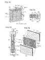
- FIGS. 6A-6C are illustrations of a filtration unit according to the invention.
- FIGS. 7A-7D illustrate a filtration unit according to the invention
- FIGS. 8A and 8B illustrate regeneration of the filtration unit according to the invention
- FIG. 9 is an illustration for describing the operation conditions of the filtration device according to the invention.
- FIGS. 10A and 10B illustrate filtration characteristics according to the invention
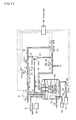
- FIG. 11 is an illustration for describing a filtration device according to the invention.
- FIG. 12 is an illustration for describing the operation conditions of the filtration device according to the invention.
- FIG. 13 is an illustration for describing a prior-art filtration system
- FIG. 14 is an illustration for describing a CMP machine
- FIG. 15 is an illustration for describing a CMP machine system.
- a “colloidal solution” refers to a state wherein microparticles of diameters of 1 nm to 1 ⁇ m are dispersed in a medium. These microparticles undergo Brownian motion and have a property of passing through ordinary filter paper but not passing through a semipermeable film. These microparticles also have a property of being extremely slow in coagulation rate, which is considered to be due to the reduced opportunity of mutual approach of the microparticles resulting from the acting of electrostatic repulsive forces among the microparticles.
- sol is used substantially synonymously to “colloidal solution,” and unlike a gel, a sol is dispersed in liquid, exhibits fluidity, and the microparticles undergo active Brownian motion.
- a “gel” refers to a state wherein colloidal particles have lost their abilities to move independently and have grouped together and solidified. For example, though agar or gelatin becomes dispersed and becomes a gel when dissolved in warm water, this sol loses fluidity and turns to a gel when cooled. Among gels are hydrogels, which have a high liquid content, and xerogels, which are somewhat dry.
- Causes of gelation include drying by removal of the water that is the dispersant, adjustment of the pH of a silica slurry (pH 9 to 10) to pH 6 to 7 by addition of an electrolyte, reduction of fluidity by cooling, etc.
- a “slurry” refers to a colloidal solution or sol, which is used for abrading and is prepared by mixing particles, a liquid, and chemicals.
- An abrasive used in CMP is called a “CMP slurry.”
- CMP slurry An abrasive used in CMP is called a “CMP slurry.”
- CMP slurries include silica abrasives, aluminum oxide (alumina) abrasives, cerium oxide (ceria) abrasives, etc. Among these, silica abrasives are used most often, and among such silica abrasives, colloidal silica is used widely.
- Colloidal silica is a dispersion in which silica ultramicroparticles with a colloid size of 7 to 300 nm are dispersed uniformly without settling in water or an organic solvent and is also referred to as “silica sol.” With this colloidal silica, particles are monodispersed in water, and the mutual repulsive forces among the colloidal particles thus prevent the particles from settling even when left still for a year or more.
- This invention provides a method of filtering, with which objects of removal are removed by filtration from wastewater of a state wherein the objects of removal are contained in a fluid in the form of a colloidal solution or sol.
- the objects of removal take the form of a colloidal solution (sol) containing large amounts of microparticles with a particle distribution of 3 nm to 2 ⁇ m.
- examples include abrasive grains of silica, alumina, or ceria, etc., that are used in CMP and semiconductor waste, metal waste, and/or insulating film material waste that are produced by abrasion by the abrasive grains.
- W2000 tungsten abrading slurry made by Cabot Corp., was used as the CMP slurry. This slurry has a pH of 2.5 and has silica with a grain size distribution of 10 to 200 nm as its principal component.
- FIG. 1 The principles of the present invention shall now be described with reference to FIG. 1 .
- This invention is a method of removal by a filter for objects of removal, mixed in the form of a colloidal solution (sol) in a fluid (wastewater), by a gel film formed from the objects of removal.
- a gel film which is to be formed as a second filter 2 from the CMP slurry that is the colloidal solution containing the objects of removal, is formed on the surface of an organic-polymer-based first filter 1 , and these filters 1 and 2 are immersed in a fluid 3 inside a tank in order to filter wastewater containing the objects of removal.
- first filter 1 either an organic-polymer-based filter or a ceramic-based filter may be used as long as the gel film can be attached.
- a polyolefin-based polymer film with an average pore diameter of 0.25 ⁇ m and a thickness of 0.1 mm was employed.
- a photographic image of the surface of this polyolefin-based filter film is shown in FIG. 2 B.
- First filter 1 has the structure of a flat film disposed on both sides of a frame 4 and is immersed vertically into the fluid, and filtrate 7 is arranged to be taken out from a hollow part 5 of frame 4 by suction from a pump 6 .
- Second filter 2 is a gel film, which is attached to the entire surface of first filter 1 and is formed by suction and gelation of the sol of the objects of removal. Since a gel film has a jelly-like form, it is generally considered as not having the function of a filter. However, with the present invention, this gel film can be made to have the function of second filter 2 by selection of the gel film forming conditions. These forming conditions shall be described in detail later.
- second filter 2 which is a gel film of the objects of removal, from the above-described colloidal solution (sol) of the objects of removal and the filtration by which the objects of removal are removed, shall now be described with reference to FIGS. 1 and 2A.
- Numeral 1 indicates the first filter and numeral 11 indicates filter pores.
- the film that is formed as layers at the openings of filter pores 11 and on the surface of first filter 1 is the gel film of the objects of removal 13 .
- the objects of removal 13 are sucked in via first filter 1 by suction pressure from a pump, and due to the drying (dehydration) of fluid 3 by the suctioning of the water content, the particles of the objects of removal in the colloidal solution gels and binds, thereby forming on the surface of first filter 1 a large gel film that cannot pass through filter pores 11 .
- This gel film forms second filter 2 .
- wastewater in the form of a colloidal solution having the objects of removal mixed therein, exists at one side of first filter 1 , and filtrated water that has passed through first filter 1 is produced at the opposite side of first filter 1 .
- the wastewater is suctioned and made to flow in the direction of the arrow, and as the microparticles in the colloidal solution are made to approach first filter 1 by the suction, the microparticles lose their electrostatic repulsive force and gel, and a gel film, resulting from the binding of several microparticles, become adsorbed onto the surface of first filter 1 , thereby forming second filter 2 .
- this second filter 2 filtration of the wastewater is carried out as the objects of removal in the colloidal solution while being gelled. Filtrated water is suctioned from the opposite side of first filter 1 .
- FIG. 3 shows the formation conditions and the filtration amount of second filter 2 .
- the method of this invention comprises the processes of forming second filter 2 and filtering.
- the filtration rate of purified water in the filtration process differs greatly with the conditions for forming of second filter 2 , and, it becomes clear that unless the conditions for forming second filter 2 are not selected appropriately, filtration by second filter 2 , which is a gel film, can hardly be performed. This is in agreement with the fact that it had previously been the that the filtration of a colloidal solution is impossible.
- first filter 1 is disposed at the bottom of a cylindrical container 21 , 50 cc of the raw fluid of W2000 tungsten abrasion slurry 22 , made by Cabot Corp., are placed inside the container, and the formation of a gel film is carried out at various suction pressures. The remaining slurry 22 is subsequently thrown out, 10 cc of purified water 23 is placed in the container, and filtration is performed at an extremely low suction pressure. The filtration characteristics of the gel film that is to be second filter 2 can thus be examined.
- the first filter 1 used here had a diameter of 47 mm and an area of 1734 mm 2 .
- the suction pressure is set to a fixed level of ⁇ 10 cmmHg.
- a filtration rate of only 0.75 cc/hour could be achieved.
- the filtration rate of the gel film formed at a suction pressure of ⁇ 30 cmHg was approximately 1 cc/hour.
- the reason for the above results is considered to be because when the suction pressure is high, the gel film that is formed becomes less filled with fluid and thus dense and hard. The gel film is thus formed in a contracted state of low-water content in which there are hardly any paths for the permeation of purified water.
- a characteristic of the present invention is that a highly swollen gel film, which has been formed at a weak suction pressure, is used to realize filtration that makes of use of the permeation of water through this gel film.
- FIG. 4A shows the relationship between the amount of sol contained in a gel film and the filtration rate.
- the amount of sol captured by first filter 1 is determined from the filtration rate during the formation of a gel film from purified water with a slurry concentration of 3%.
- This sol amount is considered to be the amount of sol that has gelled and has become attached as second filter 2 due to drying by suction. From this it can be understood that the sol amount is low when second filter 2 is formed by weak suction. That is, the sol amount that is consumed when the filtration rate is 3 cc/hour is an extremely low amount of 0.15 cc and the filtration rate becomes higher the lower the amount of sol contained in second filter 2 .
- the degree of swelling of the sol that is, the density of the sol in the gel film as determined from the above-mentioned sol removal amount and the volume of the gel film is shown in FIG. 4 B.
- the experimental results of the film thickness of second filter 2 being 6 mm when the suction pressure is ⁇ 30 cmhg and the film thickness of second filter 2 being 4 mm when the suction pressure is ⁇ 10 cmHg indicate that the degree of swelling increases from 27 to 30, that is, indicates that the greater the suction pressure, the lower the degree of swelling and the higher the density of the sol of second filter 2 .
- What is furthermore important is that the lower the suction pressure, the thinner the film thickness and yet the greater the degree of swelling of second filter 2 , giving further grounds to what is indicated by FIG. 3B, i.e., that when second filter 2 is formed at a weak suction pressure, the filtration rate during filtering is high and filtration can be performed over a long period of time.
- FIG. 2 shows one side of the filter of FIG. 1 and is actually a schematic view that illustrates how the gel film becomes attached.
- First filter 1 is immersed in a vertically upright manner in a colloidal solution wastewater, and the wastewater is a colloidal solution in which objects of removal 13 are dispersed. Objects of removal 13 are indicated by small black circles.
- the microparticles of the objects of removal gel as they approach first filter 1 and become adsorbed onto the surface of first filter 1 .
- the gelled microparticles 14 indicated by white circles, those that are larger than the filter pores 11 of first filter 1 gradually become adsorbed and layered on the surface of first filter 1 , thereby forming second filter 2 comprising a gel film.
- second filter 2 is formed as a gel film of a high degree of swelling, and by repeating the contraction of the gel film by dehydration of the water contained in the gel film in contact with first filter 1 by suction at a weak suction pressure from the first filter 1 side and the swelling of this gel film by causing water to permeate and be replenished from the gel film in contact with the wastewater, just the water is made to permeate and be filtrated through second filter 2 .
- air bubbles 12 are sent up to first filter 1 from the bottom of the wastewater to form a parallel flow of wastewater along the surface of first filter 1 .
- This causes second filter 2 to become attached uniformly over the entire surface of first filter 1 and to become attached softly while forming gaps.
- the air flow rate is set to 1.8 liters/minute, this flow rate is selected according to the film quality of second filter 2 .
- the gelled microparticles 14 are made to become adsorbed and gradually layered on the surface of second filter 2 by the weak suction pressure.
- purified water permeates through second filter 2 and the gelled microparticles 14 , which are indicated by white circles and become layered further, and is taken out from first filter 1 as filtrated water.
- abrasive grains of silica, alumina, or ceria, etc. and processing waste, such as semiconductor waste, metal waste, and/or insulating film material waste that are produced by abrasion by the abrasive grains, become layered and captured as gel on the surface of second filter 2 and the water permeates through the gel film and can be taken out as filtrated water from first filter 1 .
- numeral 50 indicates a raw water tank.
- a pipe 51 is disposed above tank 50 as a wastewater supply means, and fluid having objects of removal mixed therein flows through this pipe 51 .
- wastewater i.e., raw water
- the wastewater shall correspond to wastewater mixed with abrasive grains flowing out from a CMP machine and grinding or abrasive waste originating from abrasive grains.
- a plurality of filtration units 53 are disposed in raw water 52 stored in raw water tank 50 .
- An aeration pipe 54 such as that of a bubbling device used in an aquarium and made, for example, by opening small holes in a pipe, is disposed below filtration units 53 and positioned so that air bubbles pass by the surface of filtration unit 53 .
- This aeration pipe 54 is disposed across the entire bottom side of filtration unit 53 to enable air bubbles to be supplied uniformly across the entire surface of filtration unit 53 .
- Numeral 55 represents an air pump.
- filtration unit 53 refers to first filter 1 , frame 4 , hollow part 5 , and second filter 2 shown in FIG. 1 .
- a pipe 56 fixed to filtration unit 53 , corresponds to pipe 8 shown in FIG. 1 .
- the fluid filtrated through filtration unit 53 flows through this pipe 56 , which is connected via a valve V 1 to a magnetic pump 57 , which performs suction.
- a pipe 58 is connected from magnetic pump 57 and to valve V 3 and valve 4 via control valve CV 1 .
- a first pressure gauge 59 is provided subsequent to pipe 56 and measures the suction pressure Pin.
- a flow meter F and a second pressure gauge 60 are disposed subsequent to control valve CV 1 of pipe 58 and control is performed to maintain a fixed flow rate at flow meter 61 .
- the flow rate of air from air pump 55 is controlled by a control valve CV 2 .
- Raw water 52 supplied from pipe 51 , is stored in raw water tank 50 and is filtrated by filtration unit 53 .
- Air bubbles pass by the surface of second filter 2 attached to the filtration unit, and a parallel flow, generated by the ascending force and rupturing of air bubbles, causes the gelled objects of removal that adsorb onto second filter 2 to move and become adsorbed uniformly across the entire surface of filtration unit 53 , thereby maintaining the filtration capability and preventing it from deteriorating.
- Reference symbol 30 in FIG. 6A indicates a frame, having the shape of a picture frame, and this corresponds to frame 4 of FIG. 1 .
- Filter films 31 and 32 which are to become first filter 1 (FIG. 1) are adhered and fixed onto both sides of frame 30 .
- Filtration by filter films 31 and 32 is accomplished by applying suction, via a pipe 34 (corresponding to pipe 8 of FIG. 1 ), to an inner space 33 (corresponding to hollow part 5 of FIG. 1 ), which is surrounded by frame 30 and filter films 31 and 32 .
- Filtrated water is taken out via pipe 34 that is mounted in a sealed manner to frame 30 . Needless to say, filter films 31 and 32 and frame 30 are sealed completely so as to prevent entry of wastewater into the above-mentioned space 33 from parts other than the filter films.
- filter films 31 and 32 of FIG. 6A are thin resin films, they warp inwardly when suction is applied and may rupture in some cases. Though this space must thus be made as small as possible, in order to increase the filtration capability, space 33 must be formed to be as large as possible. This is resolved as shown in FIG. 6 B. Though only nine spaces 33 are shown in FIG. 6B, many more are formed in actuality. Also, the actually employed filter film 31 is preferably a polyolefin-based polymer film with a thickness of approximately 0.1 mm and the thin filter film is formed to have a bag-like form as shown in FIG. 6 B and is indicated as FT in FIG. 6 B.
- Frame 30 with an integral pipe 34 , is inserted inside this bag-like filter FT and the above-mentioned frame 30 and the above-mentioned filter FT are adhered together.
- Reference symbol RG indicates a presser means which presses the frame to which filter FT has been adhered from both sides. Filter FT is exposed from an opening OP of the presser means. Details shall be described again with reference to FIG. 7 .
- FIG. 6C shows an arrangement wherein filtration unit 53 itself is formed to have a cylindrical shape.
- a frame, mounted to pipe 34 is cylindrical in form and has openings OP 1 and OP 2 provided at its side face. Since side face parts corresponding to openings OP 1 and OP 2 are removed, a supporting means SUS, which supports filter film 31 , is provided between the openings. Filter film 31 is adhered to the side face.
- Filtration unit 53 of FIG. 6B shall now be described further with reference to FIG. 7 .
- part 30 a corresponding to frame 30 of FIG. 6B, shall be described with reference to FIGS. 7A and 7B.
- part 30 a is formed to have a shape similar to corrugated cardboard.
- Thin resin sheets SHT 1 and SHT 2 are overlapped and a plurality of sections SC in the vertical direction are provided in between the sheets, thereby forming spaces 33 surrounded by resin sheets SHT 1 and SHT 2 and sections SC.
- Each space 33 has a rectangular cross section with a length of 3 mm and width of 4 mm, in other words, the arrangement has a shape formed by aligning and integrating a number straws with such a rectangular cross section.
- Part 30 a maintains the filter films FT at both sides at a fixed interval with respect to each other and shall thus be referred to hereinafter as a “spacer.”
- Numerous holes HL of 1 mm diameter are formed on the surfaces of the thin resin sheets SHT 1 and SHT 2 that make up spacer 30 a , and filter films FT are adhered onto these surfaces.
- the filtrated water that is filtrated by filter films FT thus passes through holes HL and space 33 and finally flows out via pipe 34 .
- Filter films FT are adhered onto both surfaces SHT 1 and SHT 2 of spacer 30 a .
- the surfaces SHT 1 and SHT 2 of spacer 30 a have parts in which holes HL are not formed, and when parts of filter film FT 1 are adhered directly onto such parts, since the parts of filter FT 1 corresponding to parts where holes HL are not formed have no filtration capability and do not allow passage of wastewater, parts arise at which the objects of removal will not be captured. In order to prevent this phenomenon, at least two filter films FT are adhered together.
- the filter film FT 1 at the outermost side is the filter film that captures the objects of removal, and as the surface SHT 1 of spacer 30 a is approached from the side of filter film FT 1 , filter films with pores greater than the pores of filter film FT 1 are provided, and in the present case, one such filter film FT 2 is adhered. Since filter film FT 2 is thus provided in between even at parts at which holes HL of spacer 30 a are not formed, the entire surface of filter film FT 1 exhibits a filtration function, the objects of removal are captured over the entire surface of filter film FT 1 , and the second filter film is formed over the entire surfaces of the front and rear surfaces FT 1 and FT 2 . Also, though filter films FT 1 and FT 2 are shown as rectangular sheets due to reasons of illustration, they are preferably formed to have bag-like shapes as shown in FIG. 6 B.
- FIG. 7A is a completion diagram
- FIG. 7C is a sectional view obtained by sectioning along the direction of extension (vertical direction) of pipe 34 from the head part of pipe 34 as indicated by line A—A of FIG. 7A
- FIG. 7D is a sectional view obtained by sectioning filtration unit 35 in the horizontal direction as indicated by line B—B.
- spacer 30 a which is inserted inside bag-like filter film FT, has its four sides sandwiched, along with filter film FT, by presser means RG.
- the three sides that are closed in a bag-like manner and the remaining one side are fixed by adhesive agent AD 1 applied to presser means RG.
- a space SP is formed between the remaining side (the opening of the bag) and presser means RG, and the filtrated water that is produced in space 33 is suctioned into pipe 34 via this space SP.
- an adhesive agent AD 2 is applied along the entire periphery of openings OP of presser means RG, thereby completely sealing these openings and providing a structure with which fluid cannot enter inside from parts other than the filter.
- Space 33 and pipe 34 are thus in communication, providing a structure wherein, when suction is applied from pipe 34 , fluid flows towards space 33 through the pores of filter film FT and the holes HL of spacer 30 a and filtrated water is transported from space 33 to the exterior via pipe 34 .
- the structure shown in FIG. 7 is employed for the filtration unit 53 used here, and the frame (presser means RG) to which the filter film is to be mounted is the size of A 4 paper, and to be more specific, is approximately 19 cm in length, approximately 28.8 cm in width, and 5 to 10 mm in thickness. Since filtration unit 53 is actually provided at both sides of the frame, the area will be double that obtained from the above dimensions (i.e., an area of 0.109 cm 2 ). However, the number and sizes of the filtration units may be selected freely according to the size of raw water tank 50 and is determined by the required filtration rate.
- wastewater in which objects of removal are mixed in the form of a colloidal solution
- a filtration unit 53 which has just first filter 1 and does not have second filter 2 formed therein, is then immersed in this tank 50 and wastewater is circulated by sucking via pipe 56 at a weak suction pressure by pump 57 .
- the circulation path passes through filtration unit 53 , pipe 56 , valve V 1 , pump 57 , pipe 58 , control valve CV 1 , flow meter 61 , optical sensor 62 , and valve 63 , and the wastewater is thus sucked in from tank 50 and returned to tank 50 .
- second filter 2 is formed on first filter 1 ( 31 in FIG. 6) of filtration unit 53 , and in the final stage, the intended objects of removal in the colloidal solution become captured.
- first filter 1 when suction via first filter 1 is performed at a weak suction pressure by pump 57 , the microparticles of the objects of removal gel as they approach first filter 1 and become adsorbed onto the surface of first filter 1 .
- the gelled microparticles those that are larger than the filter pores 11 of first filter 1 become adsorbed and layered gradually on the surface of first filter 1 , thereby forming second filter 2 , comprising a gel film.
- the gelled microparticles having a smaller diameter than filter pores 11 pass through first filter 1 , as second filter 2 is formed, the water in the wastewater comes to be suctioned with the gaps of second filter 2 as pathways and removed as purified water through first filter 1 and the wastewater is thus filtrated.
- the concentration of microparticles contained in the filtrated water is monitored by optical sensor 62 , and filtration is started upon confirming that the amount of microparticles is lower than a desired mixing proportion.
- valve V 3 is closed in accordance with a detection signal from optical sensor 62 and valve V 4 is opened, thereby shutting off the above-mentioned circulation path. Purified water is thus taken out from valve V 4 .
- Air bubbles which are supplied constantly from air pump 55 , are supplied from aeration pipe 54 to the surface of filtration unit 53 upon being regulated by control valve CV 2 .
- FIG. 8A shows the condition of filtration unit 53 during the filtration process. Since hollow part 5 of first filter 1 is set at a negative pressure in comparison to the outer side due to the weak suction pressure, first filter 1 takes on a shape that is concave toward the inner side. Second filter 2 , which is adsorbed on the surface of first filter 1 , thus takes on a similar, inwardly-concave shape. The same applies to the gel film that is gradually adsorbed onto the surface of second filter 2 .
- first filter 1 of filtration unit 53 returns to its original state.
- Second filter 2 and the gel film adsorbed to its surface likewise return to their original state. Consequently, since the suction pressure that had caused adsorption of the gel film is first of all eliminated, the gel film loses the force of adsorption onto filtration unit 53 and, at the same time, receives an outwardly expanding force.
- the adsorbed gel film thus begins to separate from filtration unit 53 due to its own weight. It is furthermore preferable to increase the amount of air bubbles from aeration pipe 54 by approximately two times in order to promote this separation.
- second filter 2 may be formed again by circulating wastewater along the above-described circulation path. In this regeneration process, second filter 2 returns to its original state and when it has been revived to the state enabling wastewater, the wastewater is again filtrated.
- filtrated water when filtrated water is made to flow in reverse into hollow part 5 in this regeneration process, return of first filter 1 to its original state is aided and application of the hydrostatic pressure of the filtrated water applies an outwardly swelling force, and the filtrated water passes through the filter pores 11 from the inner side of first filter 1 and seeps into the boundary between first filter 1 and second filter 2 to promote separation of the gel film of second filter 2 from the surface of first filter 1 .
- the operation conditions of the filtration unit shown in FIG. 5 shall now be described with reference to FIG. 9 .
- the operation conditions are those for the case where both surfaces (area: 0.109 m 2 ) of the above-described single filtration unit 53 of A 4 size are used.
- the initial flow rate is set at 3 cc/hour (0.08 m 3 /day), at which the filtration efficiency is as good as was mentioned above, and the post-regeneration flow rate is set to this value as well.
- the air blow rate is set to 1.8 L/minute during film formation and filtration and to 3 L/minute during regeneration.
- “Pin” and “Regeneration Pin” are suction pressures and are measured by pressure gauge 59 .
- “Pout” and “Regeneration Pout” are pressures at pipe 58 and are measured by pressure gauge 60 .
- the flow rate and regeneration flow rate are measured by flow meter 61 and express the rate of filtration by suction from filtration unit 53 .
- the Y-axis at the left side indicates pressure (unit: MPa) and the negative pressure becomes greater as the X-axis is approached.
- the Y-axis at the right side indicates the flow rate (unit: cc/minute).
- the X-axis indicates the time elapsed from film formation (unit: minutes).
- a characteristic point of this invention is that the flow rate and regeneration flow rate are controlled and maintained at 3 cc/hour in the second filter 2 formation process, the filtration process, and the post-regeneration filtration process.
- Pin is set to an extremely weak suction pressure of ⁇ 0.001 MPa to ⁇ 0.005 MPa to form second filter 2 with a softly adsorbed gel film.
- Pin is increased gradually from ⁇ 0.005 MPa and filtration is continued while securing a fixed flow rate. Filtration is continued for approximately 1000 minutes and the regeneration process is carried out when the flow rate begins to decrease. This is because the gel film attaches thickly onto the surface of second filter 2 and causes clogging.
- a method of performing filtration by fixing the suction pressure at ⁇ 0.005 MPa, at which the filtration flow rate is high may also be employed.
- the filtration flow rate decreases gradually in accompaniment with the clogging of second filter 2 in this case, there is provided the advantage that the filtration time can be increased and control of pump 57 is simplified.
- the regeneration of second filter 2 can thus be carried out when the filtration flow rate decreases to or below a fixed value.
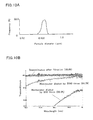
- FIG. 10A shows the particle size distribution of abrasive grains contained in a CMP slurry.
- These abrasive grains are for CMP of an interlayer insulation film comprising Si oxide and the material comprises Si oxide and is generally called silica.
- the minimum particle size was approximately 0.076 ⁇ m and the maximum particle size was 0.34 ⁇ m.
- the larger particles are aggregate particles formed by aggregation of a plurality of the particles.
- the average particle size was approximately 0.1448 ⁇ m and the distribution peaks in the range of 0.13 ⁇ m to 0.15 ⁇ m near the average particle size.
- KOH or NH3 is generally used as a slurry regulator.
- the pH lies between approximately 10 and 11.
- CMP abrasive grains that are mainly used are silica-based, alumina-based, cerium-oxide-based, or diamond-based, and besides these, there are chromium-oxide-based, iron-oxide-based, manganese-oxide-based, BaCO4-based, antimony-oxide-based, zirconia-based, and yttria-based abrasive grains.
- Silica-based abrasive grains are used for smoothing semiconductor interlayer insulation films, P—Si, SOI, etc., and smoothing of Al•glass disks.
- Alumina-based abrasive grains are used for polishing hard disks and smoothing metals in general, Si oxide films, etc.
- Cerium oxide is used for polishing glass and polishing Si oxide
- chromium oxide is used for mirror polishing steel.
- Manganese oxide and BaCO4 are used for polishing tungsten wiring.
- oxide sols with which colloid-size microparticles, comprising a metal oxide, such as silica, aluminum, zirconia, or partly comprising a hydroxide, are dispersed uniformly in water or another liquid.
- a metal oxide such as silica, aluminum, zirconia, or partly comprising a hydroxide
- Such oxide sols are used for smoothing interlayer insulation films and metals of semiconductor devices and are also being considered for use with aluminum disks and other information disks.
- FIG. 10B shows data indicating that CMP wastewater is filtrated and abrasive grains are captured.
- a specifically realized filtration device having a regeneration circuit added shall now be described with reference to FIG. 11 .
- the components that are the same as those of the filtration device shown in FIG. 5 are provided with the same symbols.
- numeral 50 indicates a raw water tank.
- a pipe 51 is disposed above tank 50 as a wastewater supply means, and fluid having objects of removal mixed therein flows through the pipe 51 .
- wastewater i.e., raw water
- the wastewater shall correspond to wastewater in which mixed abrasive grains flow out from a CMP machine and grinding or abrasive waste originates from the abrasive grains.
- a plurality of filtration units 53 are disposed in the raw water 52 stored in raw water tank 50 .
- An aeration pipe 54 such as that of a bubbling device used in an aquarium and made for example by opening small holes in a pipe, is positioned below filtration units 53 and disposed across the entire bottom sides of filtration units 53 so that bubbles pass by the surfaces of filtration units 53 .
- Numeral 55 is an air pump. Air is supplied from air pump 55 and is guided to aeration pie 54 via control valve CV 2 and air flow meter 69 for control of the air flow rate.
- filtration unit 53 refers to first filter 1 , frame 4 , hollow part 5 , and second filter 2 , as shown in FIG. 1 .
- a pipe 56 fixed to filtration unit 53 , corresponds to pipe 8 shown in FIG. 1 .
- the fluid filtrated through filtration unit 53 flows through this pipe 56 , which is connected via a valve V 1 to a magnetic pump 57 , which performs suctioning.
- a pipe 58 is connected from magnetic pump 57 and to valve V 3 and valve V 4 via a first control valve CV 1 .
- a first pressure gauge 59 is provided subsequent pipe 56 and measures the suction pressure Pin.
- a flow meter 61 and a second pressure gauge 60 are disposed subsequent first control valve CV 1 of pipe 58 and control is performed to maintain a fixed flow rate at flow meter 61 .
- Pipe 58 is connected to optical sensor 62 and from optical sensor 62 onwards, the flow path is guided to the branched pipes 63 and 64 .
- Valves V 3 and V 4 the opening and closing of which are switched in accordance with a detection signal from optical sensor 62 , are inserted in pipes 63 and 64 , pipe 63 returns filtrated water to tank 50 , and pipe 64 is arranged for taking filtrated water out to the exterior.
- the concentration of microparticles contained in the filtrated water is monitored by optical sensor 62 , and filtration is started upon confirming that the amount of microparticles is lower than a desired mixing proportion.
- valve V 3 is closed in accordance with the detection signal from optical sensor 62 and valve V 4 is opened to thereby take purified water out to the exterior.
- Auxiliary tank 70 is connected via valve V 5 to a pipe 58 and serves to collect filtrated water, and when the amount of filtrated water exceeds a fixed amount, the water overflows and is returned via pipe 71 to tank 50 .
- a valve V 2 is provided at a bottom part of auxiliary tank 70 and this is connected to pipe 56 .
- This auxiliary tank 70 is installed at a position that is approximately 10 to 20 cm higher than the liquid level of tank 50 and is used to regenerate the second filter.
- Tank 50 is furthermore provided with a pH adjuster 65 and a heater/cooler 66 for adjustment of the pH, in particular, of CMP wastewater to approximately 6 to 7 and adjustment of the wastewater temperature for promotion of gelation.
- a pH adjuster 65 for adjustment of the pH, in particular, of CMP wastewater to approximately 6 to 7 and adjustment of the wastewater temperature for promotion of gelation.
- the liquid level is monitored by liquid level gauge 67 and the inflow rate of wastewater is adjusted accordingly.
- a controller 68 which controls the operation of this filtration device, is provided for controlling control valves CV 1 and CV 2 , flow meters 61 and 69 , pump 57 , pressure gauges 59 and 60 , optical sensor 62 , etc., according to each process as indicated by the dotted lines in FIG. 11 .
- the respective valves, etc. are opened/closed and the operations of pump 57 , etc., are controlled by controller 68 in the second filter forming process, filtration process, second filter regeneration process, refiltration process, and maintenance process.
- controller 68 in the second filter forming process, filtration process, second filter regeneration process, refiltration process, and maintenance process.
- the operation conditions shall now be described according to each process.
- the operation conditions of pump 57 , optical sensor 62 , air pump 55 , and the respective valves in the respective processes are shown in FIG. 12 .
- wastewater in which objects of removal are mixed in the form of a colloidal solution
- Filtration units 53 each having just first filter 1 and not having second filter 2 formed therein, are then immersed in a spaced manner in the tank 50 .
- the number of filtration units 53 immersed is that by which the desired filtration flow rate can be obtained.
- about 10 to 40 filtration units 53 are suspended by an unillustrated supporting means. This number will obviously differ according to the filtration area of each filtration unit 53 and the total necessary filtration area of filtration units 53 is determined from the size of tank 50 .
- Wastewater in tank 50 is circulated by suctioning via pipe 56 at a weak suction pressure by pump 57 .
- the circulation path passes through filtration units 53 , pipe 56 , valve V 1 , pump 57 , pipe 58 , control valve CV 1 , flow meter 61 , optical sensor 62 , and valve V 3 , and the wastewater is thus sucked in from tank 50 and returned to tank 50 .
- Bubbles of air, supplied from air pump 55 and via control valve V 2 rise from aeration pipe 54 and are supplied to the surfaces of filtration units 53 .
- the other valves V 2 , V 4 , V 5 , V 6 , and D are closed.
- second filter 2 is formed on first filter 1 ( 31 in FIG. 6) of filtration unit 53 , and in the final stage, the intended objects of removal in the colloidal solution become captured. That is, when suction via first filter 1 is performed at a weak suction pressure by pump 57 , the microparticles of the objects of removal gel as they approach first filter 1 and become adsorbed onto the surface of first filter 1 . Of the gelled microparticles, those that are larger than the filter pores 11 of first filter 1 become adsorbed and layered gradually on the surface of first filter 1 , thereby forming second filter 2 , comprising a gel film.
- the concentration of microparticles contained in the filtrated water is monitored by optical sensor 62 in this process, and the filtration process is begun upon confirming that the amount of microparticles is lower than a desired mixing proportion.
- valve V 3 is closed in accordance with a detection signal from optical sensor 62 , valve V 4 is opened, thereby shutting off the above-mentioned circulation path, and filtrated water is removed from valve V 4 .
- control is performed by controller 68 so that the filtration flow rate at flow meter 61 will be fixed and an operation is performed to prevent as much clogging of second filter 2 as possible and to maintain a long filtration time.
- the suction pressure Pin of pump 57 is increased gradually to keep the filtration flow rate fixed.
- the operation conditions of the other parts are the same as those during the film forming process.
- valve V 4 When second filter 2 is destroyed due to some reason, the mixing in of microparticles is detected by optical sensor 62 , valve V 4 is closed, and oppositely, valve V 3 is opened to return the filtrated water to tank 50 . That is, a return to the film forming process is carried out in order to repair second filter 2 and when the conditions return to normal, the filtration process is begun again.
- pump 57 is stopped and the negative suction pressure that is applied to filtration unit 53 is eliminated.
- valve V 2 is opened and the previously collected filtrated water in auxiliary tank 70 flows in reverse through pipe 56 via valve V 1 and is delivered to the hollow part 5 of filtration unit 53 .
- first filter 1 of filtration unit 53 returns to its original state from the concave state.
- Second filter 2 and the gel film adsorbed to its surface likewise return to their original state. Consequently, since the suction pressure that had caused adsorption of the gel film is first of all eliminated, the gel film loses the force of adsorption onto filtration unit 53 and, at the same time, receives an outwardly expanding force.
- auxiliary tank 70 is disposed at a position that is higher than the liquid level of tank 50 , a hydrostatic pressure due to the height difference is applied by the reverse flow of filtrated water from auxiliary tank 70 , thus applying a further force that swells first filter 1 and second filter 2 of filtration unit 53 outwards.
- the adsorbed gel film thus begins to separate from filtration unit 53 due to its own weight and hydrostatic pressure. It is furthermore preferable to increase the amount of bubbles from aeration pipe 54 by approximately two times in order to promote this separation.
- second filter 2 may be reformed by circulating wastewater along the above-described circulation path.
- second filter 2 returns to its original state and when it has been revived to the state enabling wastewater filtration, the wastewater filtration is carried out again.
- valve V 2 is closed and valve V 5 is opened to collect filtrated water in auxiliary tank 70 for the next regeneration process.
- the refiltration process is begun and the wastewater filtration is started again.
- the operation conditions are the same as the filtration process.
- the concentration of the objects of removal in the wastewater in raw water tank 50 increases and the wastewater comes to have a considerable viscosity.
- the filtration operation is stopped and a transition to the maintenance process is carried out.
- the maintenance process includes draining out the filtrated water in pipes 56 and 58 and draining out the wastewater in tank 50 and the gel that has collected at the bottom of tank 50 .
- pump 57 and air pump 55 are stopped, control valve CV 1 and valves V 1 , V 2 , and V 5 are opened, and the filtrated water in pipes 56 and 58 and auxiliary tank 70 are drained out to the exterior by a draining valve D provided at pipe 56 .
- the system is left still for coagulating sedimentation, thus making concentrated slurry collect at the bottom of tank 50 , and this gel-like concentrated slurry is recovered by opening valve V 6 .
- the recovered concentrated slurry is compressed or dried by heating to remove the water contained therein and thereby further reduce its weight. The amount of slurry to be handled as industrial weight can thereby be reduced significantly.
- the supernatant wastewater is likewise drained out via valve V 6 and is returned to tank 50 in the subsequent filtration process.
- a filter film with pores smaller than such microparticles should be employed.
- this invention realizes a filtration device that enables, by formation of a gel film filter, the filtration of the objects of removal of a colloidal solution without the use of a filter film with pores that are 0.15 ⁇ m or less.
- the gel film filter is formed from a fluid of the objects of removal contained in a sol, filtration without a coagulant or other chemical and without using a filter with microscopic pores is realized.
- the second filter comprising the gel film can be formed by gelling of microparticles onto the surface of the first filter, and by setting a weak suction pressure and suctioning the wastewater slowly, a filtration device of extremely high filtration efficiency is realized.
- the second filter comprising the gel film and keeping the filtration flow rate or suction pressure fixed, a filtration device that is extremely unlikely to be subject to clogging and having an extremely long filtration time is realized.
- filtration of CMP slurries used for manufacture of CSP semiconductor devices is realized and a filtration device is realized that enables the large quantities of abrasive grains contained in a CMP slurry and the electrode material waste, silicon and silicon oxide film waste, which are discharged by CMP, to be filtrated at the same time.
- the filtration device that is provided is one by which the regeneration of the second filter can be carried out readily.
- the filtration device is thus one that enables the filtration process, regeneration process, and refiltration process to be repeated several times and enable filtration to be continued over an extremely long period of time.
- the gel film of the second filter that has become adsorbed onto the surface of the first filter is separated using the outwardly swelling force of the filtration unit as it returns to its original state by simply stopping the suction by the pump in the process of regenerating the second filter.
- This invention thus provides the advantage of making the burdensome process of reverse washing, which was required with prior-art filtration devices, completely unnecessary.
- the advantage by increasing the amount of bubbles in the regeneration step in comparison to that during the filtration step, forces generated by the ascending force and rupturing of the bubbles are added to the surface of the first filter to thereby promote the separation of the gel film of the second film.
- hydrostatic pressure due to height difference can be applied additionally by reverse flow of filtrated water from the auxiliary tank to the filtration unit to thereby further promote the separation of the gel film.
Abstract
Description
Claims (19)
Applications Claiming Priority (2)
| Application Number | Priority Date | Filing Date | Title |
|---|---|---|---|
| JP2001334302A JP4353665B2 (en) | 2001-10-31 | 2001-10-31 | Filtration device |
| JP2001-334302 | 2001-10-31 |
Publications (2)
| Publication Number | Publication Date |
|---|---|
| US20030089647A1 US20030089647A1 (en) | 2003-05-15 |
| US6830679B2 true US6830679B2 (en) | 2004-12-14 |
Family
ID=19149452
Family Applications (1)
| Application Number | Title | Priority Date | Filing Date |
|---|---|---|---|
| US10/284,457 Expired - Fee Related US6830679B2 (en) | 2001-10-31 | 2002-10-31 | Filtration device |
Country Status (5)
| Country | Link |
|---|---|
| US (1) | US6830679B2 (en) |
| JP (1) | JP4353665B2 (en) |
| KR (1) | KR100562449B1 (en) |
| CN (1) | CN1272086C (en) |
| TW (1) | TW570835B (en) |
Cited By (21)
| Publication number | Priority date | Publication date | Assignee | Title |
|---|---|---|---|---|
| US20040262209A1 (en) * | 2003-04-25 | 2004-12-30 | Hiroyuki Umezawa | Filtration apparatus |
| KR100562449B1 (en) * | 2001-10-31 | 2006-03-20 | 산요 아쿠아 테크노 가부시끼가이샤 | Filtering apparatus |
| US7014770B2 (en) | 2002-05-17 | 2006-03-21 | Sanyo Electric Co., Ltd. | Filtering method of a colloidal solution |
| WO2006045082A1 (en) * | 2004-10-20 | 2006-04-27 | Baker Hughes Incorporated | Methods for removing metals from water |
| US20090274596A1 (en) * | 2006-02-24 | 2009-11-05 | Ihi Compressor And Machinery Co., Ltd. | Method and apparatus for processing silicon particles |
| US20110011807A1 (en) * | 2007-12-06 | 2011-01-20 | Mann+Hummel Gmbh | Device and method for operating a fuel filter |
| US20110174745A1 (en) * | 2008-09-24 | 2011-07-21 | Hyung Il Kim | Apparatus and method for supplying slurry for a semiconductor |
| US20110180493A1 (en) * | 2009-12-18 | 2011-07-28 | Hilti Aktiengesellschaft | Device and method for processing a cooling and rinsing liquid |
| RU2469767C2 (en) * | 2010-12-13 | 2012-12-20 | Федеральное государственное образовательное учреждение высшего профессионального образования "Казанский государственный архитектурно-строительный университет" (КазГАСУ) | Precoat cartridge filter |
| US20120325731A1 (en) * | 2010-09-03 | 2012-12-27 | Kabushiki Kaisha Toshiba | Wastewater treatment method |
| US8504305B2 (en) | 1998-12-17 | 2013-08-06 | Hach Company | Anti-terrorism water quality monitoring system |
| US20130228227A1 (en) * | 2012-03-02 | 2013-09-05 | Calco Environmental Group Ltd. | Siphon actuated filtration process |
| US20140048482A1 (en) * | 2011-04-25 | 2014-02-20 | Ngk Insulators, Ltd. | Method for cleaning ceramic filter |
| US8696404B2 (en) | 2011-12-21 | 2014-04-15 | WD Media, LLC | Systems for recycling slurry materials during polishing processes |
| US8920619B2 (en) | 2003-03-19 | 2014-12-30 | Hach Company | Carbon nanotube sensor |
| US8958917B2 (en) | 1998-12-17 | 2015-02-17 | Hach Company | Method and system for remote monitoring of fluid quality and treatment |
| US9056783B2 (en) | 1998-12-17 | 2015-06-16 | Hach Company | System for monitoring discharges into a waste water collection system |
| US20170072344A1 (en) * | 2015-09-10 | 2017-03-16 | 19346124 Ontario Inc. | Methods and systems for dewatering solid particles in a contaminated liquid mixture |
| RU169691U1 (en) * | 2015-05-21 | 2017-03-28 | Владимир Эрнестович Петров | Water purifier |
| US20190077049A1 (en) * | 2015-07-10 | 2019-03-14 | Nitta Haas Incorporated | Polishing pad material purification system |
| TWI669491B (en) * | 2018-04-02 | 2019-08-21 | 日益電機股份有限公司 | Monitorable filter control system |
Families Citing this family (20)
| Publication number | Priority date | Publication date | Assignee | Title |
|---|---|---|---|---|
| JP3634792B2 (en) * | 2001-10-31 | 2005-03-30 | 三洋電機株式会社 | Removal method of object to be removed |
| JP3634791B2 (en) * | 2001-10-31 | 2005-03-30 | 三洋電機株式会社 | Removal method of object to be removed |
| US6810365B1 (en) * | 2002-06-13 | 2004-10-26 | The United States Of America As Represented By The Secretary Of The Navy | Monitoring waste liquid to determine membrane cleansing performance |
| EP1668298A4 (en) * | 2003-09-17 | 2010-04-14 | Sionex Corp | Solid-state flow generator and related systems, applications, and methods |
| JP4233484B2 (en) * | 2003-11-06 | 2009-03-04 | 三洋電機株式会社 | Fluid coagulation treatment apparatus and coagulation treatment method using the same |
| CN100525891C (en) * | 2004-02-27 | 2009-08-12 | 泽农技术合伙公司 | Water filtration using immersed membranes |
| JP2005313154A (en) * | 2004-03-29 | 2005-11-10 | Sanyo Electric Co Ltd | High concentration particle concentrate, manufacturing method for high concentration particle concentrate, powder and manufacturing method for powder |
| JP4368249B2 (en) * | 2004-06-01 | 2009-11-18 | 三洋電機株式会社 | Treatment apparatus and treatment method of water to be treated using the same |
| US8002990B2 (en) * | 2007-07-27 | 2011-08-23 | Kx Technologies, Llc | Uses of fibrillated nanofibers and the removal of soluble, colloidal, and insoluble particles from a fluid |
| TWI381160B (en) * | 2008-06-18 | 2013-01-01 | Ind Tech Res Inst | Device for setting filter media sample for gas-absorption |
| CN102580378B (en) * | 2011-01-14 | 2014-07-09 | 中国石油化工股份有限公司 | Filter device for polyolefin catalyst filter liquid |
| JP2013056298A (en) * | 2011-09-08 | 2013-03-28 | Fuji Electric Co Ltd | Filtering apparatus and method for operating the apparatus |
| WO2014083590A1 (en) * | 2012-11-28 | 2014-06-05 | 株式会社クラレ | Coolant regeneration method and coolant regeneration device |
| JP6088360B2 (en) * | 2013-06-03 | 2017-03-01 | パナソニック株式会社 | Filtration device |
| JP6088359B2 (en) * | 2013-06-03 | 2017-03-01 | パナソニック株式会社 | Filtration device |
| US9597627B2 (en) * | 2014-10-19 | 2017-03-21 | Wei Zhang (William) | Regenerative air purification system and method |
| USRE46804E1 (en) * | 2014-01-07 | 2018-04-24 | Wei Zhang | Regenerative air purification system and method |
| CN104148176A (en) * | 2014-08-11 | 2014-11-19 | 江苏申凯包装高新技术股份有限公司 | Glue filtering device |
| CN108339214B (en) * | 2018-03-16 | 2020-10-27 | 李秉京 | Fire engine with water tank heating function |
| KR102496736B1 (en) * | 2020-04-19 | 2023-02-10 | 주식회사 에버 | Diatomite filter |
Citations (6)
| Publication number | Priority date | Publication date | Assignee | Title |
|---|---|---|---|---|
| US4872988A (en) * | 1988-02-02 | 1989-10-10 | Culkin Joseph B | Method and device for separation of colloidal suspensions |
| US5269934A (en) * | 1992-10-06 | 1993-12-14 | Chevron Research And Technology Company | Removal of oily residues from aqueous waste streams |
| US6547968B1 (en) * | 1999-07-30 | 2003-04-15 | Zenon Environmental Inc. | Pulsed backwash for immersed membranes |
| US20030089647A1 (en) * | 2001-10-31 | 2003-05-15 | Motoyuki Tsuihiji | Filtration device |
| US20030094426A1 (en) * | 2001-10-31 | 2003-05-22 | Hiroyuki Umezawa | Method of filtering |
| US20030095894A1 (en) * | 2001-10-31 | 2003-05-22 | Hiroyuki Umezawa | Method of filtering |
Family Cites Families (3)
| Publication number | Priority date | Publication date | Assignee | Title |
|---|---|---|---|---|
| KR950012555B1 (en) * | 1992-06-24 | 1995-10-18 | 금성일렉트론주식회사 | Memory cell capacitor |
| KR100473538B1 (en) * | 1996-06-05 | 2005-05-16 | 이아트로스 리미티드 | Irradiation device and method for fluids especially for body fluids |
| JP3315971B2 (en) * | 1999-05-27 | 2002-08-19 | 三洋電機株式会社 | Wastewater regeneration system |
-
2001
- 2001-10-31 JP JP2001334302A patent/JP4353665B2/en not_active Expired - Fee Related
-
2002
- 2002-10-15 TW TW091123661A patent/TW570835B/en not_active IP Right Cessation
- 2002-10-30 KR KR1020020066322A patent/KR100562449B1/en not_active IP Right Cessation
- 2002-10-31 US US10/284,457 patent/US6830679B2/en not_active Expired - Fee Related
- 2002-10-31 CN CNB021479526A patent/CN1272086C/en not_active Expired - Fee Related
Patent Citations (6)
| Publication number | Priority date | Publication date | Assignee | Title |
|---|---|---|---|---|
| US4872988A (en) * | 1988-02-02 | 1989-10-10 | Culkin Joseph B | Method and device for separation of colloidal suspensions |
| US5269934A (en) * | 1992-10-06 | 1993-12-14 | Chevron Research And Technology Company | Removal of oily residues from aqueous waste streams |
| US6547968B1 (en) * | 1999-07-30 | 2003-04-15 | Zenon Environmental Inc. | Pulsed backwash for immersed membranes |
| US20030089647A1 (en) * | 2001-10-31 | 2003-05-15 | Motoyuki Tsuihiji | Filtration device |
| US20030094426A1 (en) * | 2001-10-31 | 2003-05-22 | Hiroyuki Umezawa | Method of filtering |
| US20030095894A1 (en) * | 2001-10-31 | 2003-05-22 | Hiroyuki Umezawa | Method of filtering |
Cited By (33)
| Publication number | Priority date | Publication date | Assignee | Title |
|---|---|---|---|---|
| US9069927B2 (en) | 1998-12-17 | 2015-06-30 | Hach Company | Anti-terrorism water quality monitoring system |
| US9056783B2 (en) | 1998-12-17 | 2015-06-16 | Hach Company | System for monitoring discharges into a waste water collection system |
| US8577623B2 (en) | 1998-12-17 | 2013-11-05 | Hach Company | Anti-terrorism water quality monitoring system |
| US8504305B2 (en) | 1998-12-17 | 2013-08-06 | Hach Company | Anti-terrorism water quality monitoring system |
| US8958917B2 (en) | 1998-12-17 | 2015-02-17 | Hach Company | Method and system for remote monitoring of fluid quality and treatment |
| US9015003B2 (en) | 1998-12-17 | 2015-04-21 | Hach Company | Water monitoring system |
| US9588094B2 (en) | 1998-12-17 | 2017-03-07 | Hach Company | Water monitoring system |
| KR100562449B1 (en) * | 2001-10-31 | 2006-03-20 | 산요 아쿠아 테크노 가부시끼가이샤 | Filtering apparatus |
| US7014770B2 (en) | 2002-05-17 | 2006-03-21 | Sanyo Electric Co., Ltd. | Filtering method of a colloidal solution |
| US9739742B2 (en) | 2003-03-19 | 2017-08-22 | Hach Company | Carbon nanotube sensor |
| US8920619B2 (en) | 2003-03-19 | 2014-12-30 | Hach Company | Carbon nanotube sensor |
| US20040262209A1 (en) * | 2003-04-25 | 2004-12-30 | Hiroyuki Umezawa | Filtration apparatus |
| US20060266686A1 (en) * | 2003-04-25 | 2006-11-30 | Sanyo Aqua Technology Co., Ltd. | Filtration apparatus |
| WO2006045082A1 (en) * | 2004-10-20 | 2006-04-27 | Baker Hughes Incorporated | Methods for removing metals from water |
| US7297278B2 (en) * | 2004-10-20 | 2007-11-20 | Baker Hughes Incorporated | Methods for removing metals from water |
| US20060108289A1 (en) * | 2004-10-20 | 2006-05-25 | Baker Hughes Incorporated | Methods for removing metals from water |
| US20090274596A1 (en) * | 2006-02-24 | 2009-11-05 | Ihi Compressor And Machinery Co., Ltd. | Method and apparatus for processing silicon particles |
| US20110011807A1 (en) * | 2007-12-06 | 2011-01-20 | Mann+Hummel Gmbh | Device and method for operating a fuel filter |
| US8794449B2 (en) * | 2007-12-06 | 2014-08-05 | Mann+Hummel Gmbh | Device and method for operating a fuel filter |
| US20110174745A1 (en) * | 2008-09-24 | 2011-07-21 | Hyung Il Kim | Apparatus and method for supplying slurry for a semiconductor |
| US20110180493A1 (en) * | 2009-12-18 | 2011-07-28 | Hilti Aktiengesellschaft | Device and method for processing a cooling and rinsing liquid |
| US20120325731A1 (en) * | 2010-09-03 | 2012-12-27 | Kabushiki Kaisha Toshiba | Wastewater treatment method |
| US8512570B2 (en) * | 2010-09-03 | 2013-08-20 | Kabushiki Kaisha Toshiba | Wastewater treatment method |
| RU2469767C2 (en) * | 2010-12-13 | 2012-12-20 | Федеральное государственное образовательное учреждение высшего профессионального образования "Казанский государственный архитектурно-строительный университет" (КазГАСУ) | Precoat cartridge filter |
| US20140048482A1 (en) * | 2011-04-25 | 2014-02-20 | Ngk Insulators, Ltd. | Method for cleaning ceramic filter |
| US10166512B2 (en) * | 2011-04-25 | 2019-01-01 | Ngk Insulators, Ltd. | Method for cleaning ceramic filter |
| US8696404B2 (en) | 2011-12-21 | 2014-04-15 | WD Media, LLC | Systems for recycling slurry materials during polishing processes |
| US20130228227A1 (en) * | 2012-03-02 | 2013-09-05 | Calco Environmental Group Ltd. | Siphon actuated filtration process |
| RU169691U1 (en) * | 2015-05-21 | 2017-03-28 | Владимир Эрнестович Петров | Water purifier |
| US20190077049A1 (en) * | 2015-07-10 | 2019-03-14 | Nitta Haas Incorporated | Polishing pad material purification system |
| US20170072344A1 (en) * | 2015-09-10 | 2017-03-16 | 19346124 Ontario Inc. | Methods and systems for dewatering solid particles in a contaminated liquid mixture |
| US20230001335A1 (en) * | 2015-09-10 | 2023-01-05 | 1934612 Ontario Inc. | Methods and systems for dewatering solid particles in a contaminated liquid mixture |
| TWI669491B (en) * | 2018-04-02 | 2019-08-21 | 日益電機股份有限公司 | Monitorable filter control system |
Also Published As
| Publication number | Publication date |
|---|---|
| KR20030036016A (en) | 2003-05-09 |
| TW570835B (en) | 2004-01-11 |
| KR100562449B1 (en) | 2006-03-20 |
| JP2003135940A (en) | 2003-05-13 |
| JP4353665B2 (en) | 2009-10-28 |
| CN1272086C (en) | 2006-08-30 |
| US20030089647A1 (en) | 2003-05-15 |
| CN1416935A (en) | 2003-05-14 |
Similar Documents
| Publication | Publication Date | Title |
|---|---|---|
| US6830679B2 (en) | Filtration device | |
| US20080314832A1 (en) | Method of filtering | |
| US7381323B2 (en) | Filtration apparatus | |
| JP3557197B2 (en) | Filtration method of colloid solution | |
| US20030095894A1 (en) | Method of filtering | |
| JP2001038152A (en) | Removing method of material to be removed in fluid | |
| US7157012B2 (en) | Water treatment device and water treatment method using the same | |
| US7438804B2 (en) | Coagulation treatment apparatus | |
| JP4544831B2 (en) | Filtration device | |
| JP4726396B2 (en) | Filtration device | |
| JP3825648B2 (en) | Fluid filtration method | |
| JP4353972B2 (en) | Method for recovering gel film generated from CMP waste water | |
| JP4535689B2 (en) | Fluid filtration method | |
| JP2004321998A (en) | Filter apparatus | |
| JP2004290814A (en) | Waste water treatment apparatus and waste water treatment method using it | |
| JP2005152879A (en) | Coagulation treatment device for fluid and coagulation treatment method employing it | |
| JP2004290813A (en) | Water treatment apparatus and water treatment method using it | |
| JP2001347456A (en) | Filtering method of cmp drain |
Legal Events
| Date | Code | Title | Description |
|---|---|---|---|
| AS | Assignment |
Owner name: SANYO ELECTRIC CO., LTD., JAPAN Free format text: ASSIGNMENT OF ASSIGNORS INTEREST;ASSIGNORS:TSUIHIJI, MOTOYUKI;IINUMA, HIROFUMI;UMEZAWA, HIROYUKI;AND OTHERS;REEL/FRAME:013700/0840 Effective date: 20030114 |
|
| FEPP | Fee payment procedure |
Free format text: PAYOR NUMBER ASSIGNED (ORIGINAL EVENT CODE: ASPN); ENTITY STATUS OF PATENT OWNER: LARGE ENTITY |
|
| FPAY | Fee payment |
Year of fee payment: 4 |
|
| AS | Assignment |
Owner name: PANASONIC CORPORATION, JAPAN Free format text: ASSIGNMENT OF ASSIGNORS INTEREST;ASSIGNOR:SANYO ELECTRIC CO., LTD.;REEL/FRAME:027155/0514 Effective date: 20110811 |
|
| FEPP | Fee payment procedure |
Free format text: PAYOR NUMBER ASSIGNED (ORIGINAL EVENT CODE: ASPN); ENTITY STATUS OF PATENT OWNER: LARGE ENTITY Free format text: PAYER NUMBER DE-ASSIGNED (ORIGINAL EVENT CODE: RMPN); ENTITY STATUS OF PATENT OWNER: LARGE ENTITY |
|
| FPAY | Fee payment |
Year of fee payment: 8 |
|
| REMI | Maintenance fee reminder mailed | ||
| LAPS | Lapse for failure to pay maintenance fees | ||
| STCH | Information on status: patent discontinuation |
Free format text: PATENT EXPIRED DUE TO NONPAYMENT OF MAINTENANCE FEES UNDER 37 CFR 1.362 |
|
| FP | Lapsed due to failure to pay maintenance fee |
Effective date: 20161214 |