US6819518B1 - Method and apparatus for self servowriting of tracks of a disk drive using a servo control loop having a two-dimensional digital state compensator - Google Patents
Method and apparatus for self servowriting of tracks of a disk drive using a servo control loop having a two-dimensional digital state compensator Download PDFInfo
- Publication number
- US6819518B1 US6819518B1 US10/280,603 US28060302A US6819518B1 US 6819518 B1 US6819518 B1 US 6819518B1 US 28060302 A US28060302 A US 28060302A US 6819518 B1 US6819518 B1 US 6819518B1
- Authority
- US
- United States
- Prior art keywords
- track
- servo
- burst patterns
- servo burst
- target
- Prior art date
- Legal status (The legal status is an assumption and is not a legal conclusion. Google has not performed a legal analysis and makes no representation as to the accuracy of the status listed.)
- Expired - Fee Related, expires
Links
Images


Classifications
-
- G—PHYSICS
- G11—INFORMATION STORAGE
- G11B—INFORMATION STORAGE BASED ON RELATIVE MOVEMENT BETWEEN RECORD CARRIER AND TRANSDUCER
- G11B5/00—Recording by magnetisation or demagnetisation of a record carrier; Reproducing by magnetic means; Record carriers therefor
- G11B5/48—Disposition or mounting of heads or head supports relative to record carriers ; arrangements of heads, e.g. for scanning the record carrier to increase the relative speed
- G11B5/58—Disposition or mounting of heads or head supports relative to record carriers ; arrangements of heads, e.g. for scanning the record carrier to increase the relative speed with provision for moving the head for the purpose of maintaining alignment of the head relative to the record carrier during transducing operation, e.g. to compensate for surface irregularities of the latter or for track following
- G11B5/596—Disposition or mounting of heads or head supports relative to record carriers ; arrangements of heads, e.g. for scanning the record carrier to increase the relative speed with provision for moving the head for the purpose of maintaining alignment of the head relative to the record carrier during transducing operation, e.g. to compensate for surface irregularities of the latter or for track following for track following on disks
- G11B5/59633—Servo formatting
Definitions
- the present invention relates to magnetic disk drives, and more particularly, to self servowriting of tracks on a rotating magnetic disk medium.
- servotrack information is a critical process in the manufacture of a disk drive.
- servotrack information is written with a specialized servowriting instrument mounted on a large granite block to minimize external vibration effects.
- Increasing track densities and decreasing disk-drive size has led to the investigation of self servowriting techniques.
- One issue confronting the use of self servowriting is track-to-track or radial error propagation and amplification of written-in errors and imperfections with respect to a perfectly circular track.
- U.S. Pat. No. 5,907,447 to Yarmchuk et al. describes reduction of radial error propagation by generating a correction signal using a filter applied to a position error signal (PES) to reduce a closed-loop response of a track-following servo loop to less than unity at frequencies equal to integer multiples of the disk rotation frequency. While permitting implementation of self servowriting with reduced radial error propagation, the PES filtering technique of the Yarmchuk patent fails to readily support increasingly aggressive track densities.
- PES position error signal
- the present invention may be embodied in a method, implemented in a magnetic disk drive, for writing servo burst patterns for tracks on a rotating magnetic disk medium.
- a first reference track defined by previously written servo burst patterns
- the servo control loop has a closed-loop response and includes a two-dimensional digital state compensator having first and second inputs and first and second outputs.
- the first input receives position error signals and the first output generates control signals for positioning a transducer head with respect to the selected track during track following.
- the second output generates track-following state variables during track following, and the second input receives combined track-following state variables. Accordingly, the track-following state variables generated at the second output during the writing of the servo burst patterns on the first target radial location are stored.
- a second reference track defined by previously written servo burst patterns, is followed using the servo control loop while writing servo burst patterns at a second target radial location.
- the track-following state variables generated at the second output during the writing of the servo burst patterns at the second target radial location are stored.
- a third reference track defined by the previously written servo burst patterns at the first and second radial target locations, is followed using the servo control loop while writing servo burst patterns at a third target radial location.
- the stored track-following state variables generated at the second output during writing of the servo burst patterns at the first and second target radial locations are combined, and the combined track following state variables are applied to the second input during writing of the servo burst patterns at the third target radial location.
- the dimensions of the two-dimensional digital state compensator may be circumferential position and radial position.
- the first reference track may be offset from the second reference track by more than one servo track
- the third reference track may be offset from the second reference track by at least one servo track.
- Each radial location may be offset from the corresponding reference track by at least one servo track.
- k is the reference track number
- t is a servo wedge number or time
- u k (t) is the control signals for positioning the transducer head
- x k (t) is a state vector in a first dimension or time
- ⁇ k (t) is the combined track-following state variables, in a second dimension or track number
- ⁇ k (t) is the track-following state variables generated during writing of the servo burst patterns
- a 11 , A 12 , A 21 , A 22 , B 11 , B 21 , C 11 , C 12 are matrices of appropriate dimensions.
- k is the reference track number
- t is a servo wedge number or time
- (A g , B g , C g ) is a state space description of a head disk assembly
- u k (t) is the control signals for positioning the transducer head
- x k (t) is a state vector in the first dimension or time
- ⁇ k (t) is the combined track-following state variable, in a second dimension or track number
- ⁇ k+1 (t) is the track-following state variables generated during writing of the servo burst patterns
- K e is an estimator gain
- K c is a compensator gain
- a reference track defined by previously formed servo burst patterns on the magnetic disk medium, is followed using a servo control loop while forming servo burst patterns defining a first target track.
- the servo loop has a closed-loop response and includes a two-dimensional digital state compensator having first and second inputs and first and second outputs.
- the first input receives position error signals (PES) and the first output generates control signals for positioning a transducer head with respect to the selected track during track following.
- the second output generates track-following state variables during track following, and the second input receives stored track-following state variables.
- PES position error signals
- the track-following state variables generated at the second output while forming the servo burst patterns defining the first target track are stored.
- the first target track is followed using the servo control loop while forming servo burst patterns defining a second target track.
- the stored track-following state variables generated at the second output while forming the servo burst patterns defining the first target track are applied to the second input.
- the dimensions of the two-dimensional digital state compensator may be circumferential position and radial position.
- the first target track may be offset from the reference track by one servo track, and the second target track may be offset from the first target track by one servo track.
- the first target track may be offset from the reference track by more than one servo track, and the second target track may be offset from the first target track by more than one servo track.
- k is the track number
- t is a servo wedge number or time
- u k (t) is the control signals for positioning the transducer head
- x k (t) is a state vector in a first dimension or time
- ⁇ k (t) is the stored track-following state variables, in a second dimension or track number
- ⁇ k+1 (t) is the track-following state variables that are stored while forming the servo burst patterns
- a 11 , A 12 , A 21 , A 22 , B 11 , B 21 , C 11 , C 12 are matrices of appropriate dimensions.
- k is the track number
- t is a servo wedge number or time
- (A g , B g , C g ) is a state space description of a head disk assembly
- u k (t) is the control signals for positioning the transducer head
- x k (t) is a state vector in the first dimension or time
- ⁇ k (t) is the track-following state variable, in a second dimension or track number
- ⁇ k+1 (t) is the track-following state variables that are stored while forming the servo burst patterns
- K e is an estimator gain
- K c is a compensator gain
- FIG. 1 is a flow chart illustrating a first embodiment of a self servo-writing method for defining tracks on a rotating magnetic disk medium of a disk drive, using a track-following servo-control loop having a two-dimensional digital state compensator, according to the present invention.
- FIG. 2 is a block diagram of the track-following servo control loop.
- FIG. 3 is a block diagram of a disk drive coupled to a host for implementing the determining method of FIG. 1 .
- FIG. 4 is a schematic diagram illustrating a transducer head, having non-overlapping read and write elements offset by at least two servo tracks, for self-servo writing write-element-width servo bursts for defining servo tracks, according to the first embodiment of the present invention.
- FIG. 5A is a schematic diagram illustrating ideal servo tracks on a disk of a disk drive.
- FIG. 5B is a schematic diagram illustrating written servo tracks exhibiting imperfections.
- FIG. 6 is a flow chart illustrating a second embodiment of a self servo-writing method for defining tracks on a rotating magnetic disk medium of a disk drive, using a track-following servo-control loop having a two-dimensional digital state compensator, according to the present invention.
- FIG. 7 is a schematic diagram illustrating a transducer head, having non-overlapping read and write elements offset by at least two servo tracks, for self-servo writing servo bursts for defining servo tracks, according to the second embodiment of the present invention.
- the present invention may be embodied in a method 100 (FIG. 1 ), implemented in a magnetic disk drive 30 (FIG. 3 ), for writing servo burst patterns, A, B, C and D (FIG. 4 ), for servo tracks 12 on a rotating magnetic disk medium.
- a first reference track N+1 defined by previously written servo burst patterns, C and D, is followed using a servo control loop 24 (FIG. 2) while writing servo burst patterns A at a first target radial location coincident with yet to be defined servo track N+3 (step 112 ).
- the servo loop has a closed-loop response and includes a two-dimensional digital state compensator 26 having first and second inputs, I 1 and I 2 , and first and second outputs, O 1 and O 2 .
- the first input receives position error signals (PES) and the first output generates control signals u k (t) for positioning a transducer head 42 with respect to the selected track during track following.
- the second output generates track-following state variables ⁇ k+1 (t) during track following, and the second input receives combined track-following state variables ⁇ k (t).
- the track-following state variables generated at the second output during the writing of the servo burst patterns on the first target radial location are stored (step 114 ) in, for example, a table 28 .
- a second reference track N+3, defined by previously written servo burst patterns, C and D, is followed using the servo control loop while writing servo burst patterns B at a second target radial location coincident with the yet to be defined servo track N+5 (step 116 ).
- the track-following state variable generated at the second output during writing of the servo burst patterns at the second target radial location are stored (step 118 ).
- a third reference track N+4 defined by the previously written servo burst patterns, A and B, at the first and second radial target locations, is followed using the servo control loop while writing servo burst patterns D at a third target radial location coincident with the yet to be defined servo track N+6 (step 120 ).
- the stored track-following state variables generated at the second output during writing of the servo burst patterns at the first and second target radial locations are combined, and the combined track following stale variables are applied to the second input during writing of the servo burst patterns at the third target radial location.
- seed servo burst patterns, A, B, C and D, for initially defining servo tracks 12 , N and N+1 are written using a technique for forming as near perfect circular track path as practical.
- interleaved permanent and temporary servo burst patterns may be used to address timing and sensor element cross-talk issues. Accordingly, the permanent servo burst patterns may be used for track following while the temporary servo burst patterns are written, and the temporary servo burst patterns may be used for track following while the permanent servo burst patterns are written. After servo tracks are written across the entire disk surface, the temporary servo burst patterns would then revert to data sectors of the corresponding data tracks and eventually would be overwritten by user data. Also, while not explicitly described above, the servo burst patterns C centered on servo track N+4 may be written as a seed track or may be written by track following along, for example, servo track N+2.
- the PES from a reference track 12 is created by reading at least two servo burst pattern edges from, for example, patterns A and B that define the track N+4. Each of these patterns has associated with it a retrieved stored state variable ⁇ k , say ⁇ k A and ⁇ k B .
- the state output of the compensator will then be stored with reference to the presently-written servo burst pattern on the target radial location.
- the coefficients of the linear combination of stored state variables will generally be proportional to the magnitudes of the servo burst pattern elements, in this example A and B, although modifications to this rule may be made to accommodate or correct for such imperfections such as PES linearity of the read element.
- the dimensions of the two-dimensional digital state compensator 26 may be circumferential position or time t, and radial position or track number k.
- the first reference track N+1 may be offset from the second reference track N+3 by more than one servo track
- the third reference track N+4 may be offset from the second reference track by at least one servo track.
- Each radial location may be offset from the corresponding reference track by at least one servo track.
- the disk drive 30 has a head disk assembly (HDA) 32 and a sampled servo controller 34 .
- the HDA includes a rotating magnetic disk 36 having, after servo writing, distributed position information in a plurality of uniformly spaced-apart servo wedges 38 , a rotary actuator 40 that pivots relative to a base and that carries a transducer head 42 that periodically reads the position information from the servo wedges, and a voice coil motor (VCM) circuit 44 that includes a voice coil motor coupled to the rotary actuator and that responds to a control effort signal 46 .
- VCM voice coil motor
- the sampled servo controller periodically adjusts the control effort signal during a track-following operation based on the position information.
- the transducer head has a read element 48 and an offset write element 50 (FIG. 4 ).
- the write element is wider than the read element.
- the center of the read element may be spaced from a nearest edge of the write element by at least one servo track such that the elements do not overlap.
- An ideal servo track 12 is one that forms a perfect circle on the disk 36 , as shown in FIG. 5 A.
- servo information for the embedded servo wedges 38 is placed on the disk during the self servowriting operation.
- the servo information includes the servo burst patterns having edges that are placed at locations that deviate outwardly or inwardly from the ideal “center line” of the servo track circle as shown in FIG. 5 B. These apparent deviations from the ideal servo track center line can occur due to spindle runout, vibrations or movements, during servo writing operation, and media defects or noise in the region of the servo burst patterns.
- the disk drive 30 further includes a control system 54
- the HDA 32 further includes a spindle motor 60 and a preamplifier 66 .
- the control system includes the sampled servo controller 34 , and circuitry and processors that control the HDA and that provide an intelligent interface between a host 58 and the HDA for execution of read and write commands.
- the control system may have an internal microprocessor and nonvolatile memory for implementing the techniques of the invention.
- Program code for implementing the techniques of the invention may be stored in the nonvolatile memory and transferred to volatile random access memory (RAM) for execution by the microprocessor.
- the data tracks on the media surface may be divided into the storage segments.
- Each storage segment may begin with a sector of the servo wedges 38 which is followed by data sectors.
- the data sectors may include data blocks, each generally storing 512 data bytes.
- Each data block may be addressed using a logical block address (LBA).
- LBA logical block address
- the servo control loop 24 (FIG. 2) includes the HDA 32 after the track-following compensator 26 . Disturbances k to the HDA alter the resulting head position y k+1 . A track selection signal y k is compared to the bead position y k+1 to generate the PES.
- the data one number per servo wedge
- the data is stored in the lookup table 28 and used as the second input I 2 to the compensator when the next track is defined. This process is repeated for defining all of the tracks during the self servowriting process.
- a state-space model for the HDA 32 is given by
- x k g ( t+ 1) A g x k g ( t )+ B g u k ( t )
- ⁇ k is the head sensor noise
- K c the compensator gain
- K e an estimator gain
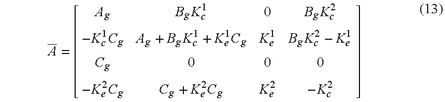
- Equation 10 is of the same form as equation 1, and the matrices A 11 , A 12 , A 21 , A 22 , B 11 , B 21 , C 11 , C 12 of equation 1 may be obtained by comparison.
- a _ [ A g B g ⁇ K c 1 0 B g ⁇ K c 2 - K c 1 ⁇ C g A g + B g ⁇ K c 1 + K e 1 ⁇ C g K e 1 B g ⁇ K c 2 - K e 1 C g 0 0 0 - K e 2 ⁇ C g C g + K e 2 ⁇ C g K e 2 - K c 2 ] ( 13 )
- a _ 11 [ A g B g ⁇ K c 1 - K e 1 ⁇ C g A g + B g ⁇ K c 1 + K e 1 ⁇ C g ] ( 14 )
- a _ 12 [ 0 B g ⁇ K c 2 K e 1 B g ⁇ K c 2 - K e 1 ]
- a _ 21 [ C g 0 - K e 2 ⁇ C g C g + K e 2 ⁇ C g ]
- a _ 22 [ 0 0 K e 2 - K e 2 ]
- Such a condition may be verified using tools such as MATLAB.
- the present invention may be embodied in a self servo-writing method 160 (FIG. 6 ), implemented in the magnetic disk drive 30 (FIG. 3 ), for defining servo tracks 12 (FIG. 7) on a rotating magnetic disk medium.
- a reference track N defined by previously formed servo burst patterns, A and B, is track followed using a servo control loop 24 (FIG. 2) while forming servo burst patterns, C and D, defining a first target track N+1 (step 162 ).
- the servo control loop has a closed-loop response and includes a two-dimensional digital state compensator 26 having first and second inputs, I 1 and I 2 , and first and second outputs, O 1 and O 2 .
- the first input receives position error signals (PES) and the first output generates control signals u k (t) for positioning a transducer head 42 with respect to the selected track during track following.
- the second output generates track-following state variables ⁇ k+1 (t) during track following, and the second input receives stored track-following state variables ⁇ k (t). Accordingly, the track-following state variables generated at the second output while forming the servo burst patterns defining the first target track are stored (step 164 ).
- the first target track is track followed using the servo control loop while servo burst patterns, A′ and B, are formed defining a second target track N+2. While forming the servo burst patterns defining the second target track, the stored track-following state variables generated at the second output while forming the servo burst pattern defining the first target track are applied to the second input (step 166 ).
- the first target track N+1 may be offset from the reference track N by one servo track
- the second target track N+2 may be offset from the first target track by one servo track.
- the tracks may be offset by more than one servo track.
Abstract
Description


Claims (24)


Priority Applications (1)
| Application Number | Priority Date | Filing Date | Title |
|---|---|---|---|
| US10/280,603 US6819518B1 (en) | 2002-10-24 | 2002-10-24 | Method and apparatus for self servowriting of tracks of a disk drive using a servo control loop having a two-dimensional digital state compensator |
Applications Claiming Priority (1)
| Application Number | Priority Date | Filing Date | Title |
|---|---|---|---|
| US10/280,603 US6819518B1 (en) | 2002-10-24 | 2002-10-24 | Method and apparatus for self servowriting of tracks of a disk drive using a servo control loop having a two-dimensional digital state compensator |
Publications (1)
| Publication Number | Publication Date |
|---|---|
| US6819518B1 true US6819518B1 (en) | 2004-11-16 |
Family
ID=33415625
Family Applications (1)
| Application Number | Title | Priority Date | Filing Date |
|---|---|---|---|
| US10/280,603 Expired - Fee Related US6819518B1 (en) | 2002-10-24 | 2002-10-24 | Method and apparatus for self servowriting of tracks of a disk drive using a servo control loop having a two-dimensional digital state compensator |
Country Status (1)
| Country | Link |
|---|---|
| US (1) | US6819518B1 (en) |
Cited By (105)
| Publication number | Priority date | Publication date | Assignee | Title |
|---|---|---|---|---|
| US20050078403A1 (en) * | 2003-10-09 | 2005-04-14 | Kabushiki Kaisha Toshiba | Method and apparatus for writing servo data in a disk drive |
| US7027253B1 (en) | 2004-08-06 | 2006-04-11 | Maxtor Corporation | Microactuator servo control during self writing of servo data |
| US20070247737A1 (en) * | 2006-04-20 | 2007-10-25 | Hitachi Global Storage Technologies Netherlands B.V. | Stable time domain radial self-servo write propagation |
| US8824081B1 (en) | 2012-03-13 | 2014-09-02 | Western Digital Technologies, Inc. | Disk drive employing radially coherent reference pattern for servo burst demodulation and fly height measurement |
| US8830617B1 (en) | 2013-05-30 | 2014-09-09 | Western Digital Technologies, Inc. | Disk drive adjusting state estimator to compensate for unreliable servo data |
| US8879191B1 (en) | 2012-11-14 | 2014-11-04 | Western Digital Technologies, Inc. | Disk drive modifying rotational position optimization algorithm to achieve target performance for limited stroke |
| US8891191B1 (en) | 2014-05-06 | 2014-11-18 | Western Digital Technologies, Inc. | Data storage device initializing read signal gain to detect servo seed pattern |
| US8891194B1 (en) | 2013-05-14 | 2014-11-18 | Western Digital Technologies, Inc. | Disk drive iteratively adapting correction value that compensates for non-linearity of head |
| US8896957B1 (en) | 2013-05-10 | 2014-11-25 | Western Digital Technologies, Inc. | Disk drive performing spiral scan of disk surface to detect residual data |
| US8902539B1 (en) | 2014-05-13 | 2014-12-02 | Western Digital Technologies, Inc. | Data storage device reducing seek power consumption |
| US8902538B1 (en) | 2013-03-29 | 2014-12-02 | Western Digital Technologies, Inc. | Disk drive detecting crack in microactuator |
| US8913342B1 (en) | 2014-03-21 | 2014-12-16 | Western Digital Technologies, Inc. | Data storage device adjusting range of microactuator digital-to-analog converter based on operating temperature |
| US8917474B1 (en) | 2011-08-08 | 2014-12-23 | Western Digital Technologies, Inc. | Disk drive calibrating a velocity profile prior to writing a spiral track |
| US8917475B1 (en) | 2013-12-20 | 2014-12-23 | Western Digital Technologies, Inc. | Disk drive generating a disk locked clock using radial dependent timing feed-forward compensation |
| US8922940B1 (en) | 2014-05-27 | 2014-12-30 | Western Digital Technologies, Inc. | Data storage device reducing spindle motor voltage boost during power failure |
| US8922938B1 (en) | 2012-11-02 | 2014-12-30 | Western Digital Technologies, Inc. | Disk drive filtering disturbance signal and error signal for adaptive feed-forward compensation |
| US8922931B1 (en) | 2013-05-13 | 2014-12-30 | Western Digital Technologies, Inc. | Disk drive releasing variable amount of buffered write data based on sliding window of predicted servo quality |
| US8922937B1 (en) | 2012-04-19 | 2014-12-30 | Western Digital Technologies, Inc. | Disk drive evaluating multiple vibration sensor outputs to enable write-protection |
| US8929022B1 (en) | 2012-12-19 | 2015-01-06 | Western Digital Technologies, Inc. | Disk drive detecting microactuator degradation by evaluating frequency component of servo signal |
| US8929021B1 (en) | 2012-03-27 | 2015-01-06 | Western Digital Technologies, Inc. | Disk drive servo writing from spiral tracks using radial dependent timing feed-forward compensation |
| US8934186B1 (en) | 2014-03-26 | 2015-01-13 | Western Digital Technologies, Inc. | Data storage device estimating servo zone to reduce size of track address |
| US8937784B1 (en) | 2012-08-01 | 2015-01-20 | Western Digital Technologies, Inc. | Disk drive employing feed-forward compensation and phase shift compensation during seek settling |
| US8941939B1 (en) | 2013-10-24 | 2015-01-27 | Western Digital Technologies, Inc. | Disk drive using VCM BEMF feed-forward compensation to write servo data to a disk |
| US8941945B1 (en) | 2014-06-06 | 2015-01-27 | Western Digital Technologies, Inc. | Data storage device servoing heads based on virtual servo tracks |
| US8947819B1 (en) | 2012-08-28 | 2015-02-03 | Western Digital Technologies, Inc. | Disk drive implementing hysteresis for primary shock detector based on a more sensitive secondary shock detector |
| US8953278B1 (en) | 2011-11-16 | 2015-02-10 | Western Digital Technologies, Inc. | Disk drive selecting disturbance signal for feed-forward compensation |
| US8953271B1 (en) | 2013-05-13 | 2015-02-10 | Western Digital Technologies, Inc. | Disk drive compensating for repeatable run out selectively per zone |
| US8958169B1 (en) | 2014-06-11 | 2015-02-17 | Western Digital Technologies, Inc. | Data storage device re-qualifying state estimator while decelerating head |
| US8970979B1 (en) | 2013-12-18 | 2015-03-03 | Western Digital Technologies, Inc. | Disk drive determining frequency response of actuator near servo sample frequency |
| US8982501B1 (en) | 2014-09-22 | 2015-03-17 | Western Digital Technologies, Inc. | Data storage device compensating for repeatable disturbance when commutating a spindle motor |
| US8982490B1 (en) | 2014-04-24 | 2015-03-17 | Western Digital Technologies, Inc. | Data storage device reading first spiral track while simultaneously writing second spiral track |
| US8995075B1 (en) | 2012-06-21 | 2015-03-31 | Western Digital Technologies, Inc. | Disk drive adjusting estimated servo state to compensate for transient when crossing a servo zone boundary |
| US8995082B1 (en) | 2011-06-03 | 2015-03-31 | Western Digital Technologies, Inc. | Reducing acoustic noise in a disk drive when exiting idle mode |
| US9001454B1 (en) | 2013-04-12 | 2015-04-07 | Western Digital Technologies, Inc. | Disk drive adjusting phase of adaptive feed-forward controller when reconfiguring servo loop |
| US9007714B1 (en) | 2014-07-18 | 2015-04-14 | Western Digital Technologies Inc. | Data storage device comprising slew rate anti-windup compensation for microactuator |
| US9013824B1 (en) | 2014-06-04 | 2015-04-21 | Western Digital Technologies, Inc. | Data storage device comprising dual read sensors and dual servo channels to improve servo demodulation |
| US9013825B1 (en) | 2014-03-24 | 2015-04-21 | Western Digital Technologies, Inc. | Electronic system with vibration management mechanism and method of operation thereof |
| US9026728B1 (en) | 2013-06-06 | 2015-05-05 | Western Digital Technologies, Inc. | Disk drive applying feed-forward compensation when writing consecutive data tracks |
| US9025269B1 (en) | 2014-01-02 | 2015-05-05 | Western Digital Technologies, Inc. | Disk drive compensating for cycle slip of disk locked clock when reading mini-wedge |
| US9047919B1 (en) | 2013-03-12 | 2015-06-02 | Western Digitial Technologies, Inc. | Disk drive initializing servo read channel by reading data preceding servo preamble during access operation |
| US9047901B1 (en) | 2013-05-28 | 2015-06-02 | Western Digital Technologies, Inc. | Disk drive measuring spiral track error by measuring a slope of a spiral track across a disk radius |
| US9047932B1 (en) | 2014-03-21 | 2015-06-02 | Western Digital Technologies, Inc. | Data storage device adjusting a power loss threshold based on samples of supply voltage |
| US9053727B1 (en) | 2014-06-02 | 2015-06-09 | Western Digital Technologies, Inc. | Disk drive opening spiral crossing window based on DC and AC spiral track error |
| US9053712B1 (en) | 2014-05-07 | 2015-06-09 | Western Digital Technologies, Inc. | Data storage device reading servo sector while writing data sector |
| US9053726B1 (en) | 2014-01-29 | 2015-06-09 | Western Digital Technologies, Inc. | Data storage device on-line adapting disturbance observer filter |
| US9058826B1 (en) | 2014-02-13 | 2015-06-16 | Western Digital Technologies, Inc. | Data storage device detecting free fall condition from disk speed variations |
| US9058827B1 (en) | 2013-06-25 | 2015-06-16 | Western Digitial Technologies, Inc. | Disk drive optimizing filters based on sensor signal and disturbance signal for adaptive feed-forward compensation |
| US9058834B1 (en) | 2013-11-08 | 2015-06-16 | Western Digital Technologies, Inc. | Power architecture for low power modes in storage devices |
| US9064537B1 (en) | 2013-09-13 | 2015-06-23 | Western Digital Technologies, Inc. | Disk drive measuring radial offset between heads by detecting a difference between ramp contact |
| US9076471B1 (en) | 2013-07-31 | 2015-07-07 | Western Digital Technologies, Inc. | Fall detection scheme using FFS |
| US9076490B1 (en) | 2012-12-12 | 2015-07-07 | Western Digital Technologies, Inc. | Disk drive writing radial offset spiral servo tracks by reading spiral seed tracks |
| US9076472B1 (en) | 2014-08-21 | 2015-07-07 | Western Digital (Fremont), Llc | Apparatus enabling writing servo data when disk reaches target rotation speed |
| US9076473B1 (en) | 2014-08-12 | 2015-07-07 | Western Digital Technologies, Inc. | Data storage device detecting fly height instability of head during load operation based on microactuator response |
| US9093105B2 (en) | 2011-12-09 | 2015-07-28 | Western Digital Technologies, Inc. | Disk drive charging capacitor using motor supply voltage during power failure |
| US9099147B1 (en) | 2014-09-22 | 2015-08-04 | Western Digital Technologies, Inc. | Data storage device commutating a spindle motor using closed-loop rotation phase alignment |
| US9111575B1 (en) | 2014-10-23 | 2015-08-18 | Western Digital Technologies, Inc. | Data storage device employing adaptive feed-forward control in timing loop to compensate for vibration |
| US9129630B1 (en) | 2014-12-16 | 2015-09-08 | Western Digital Technologies, Inc. | Data storage device employing full servo sectors on first disk surface and mini servo sectors on second disk surface |
| US9142249B1 (en) | 2013-12-06 | 2015-09-22 | Western Digital Technologies, Inc. | Disk drive using timing loop control signal for vibration compensation in servo loop |
| US9141177B1 (en) | 2014-03-21 | 2015-09-22 | Western Digital Technologies, Inc. | Data storage device employing glitch compensation for power loss detection |
| US9142235B1 (en) | 2009-10-27 | 2015-09-22 | Western Digital Technologies, Inc. | Disk drive characterizing microactuator by injecting sinusoidal disturbance and evaluating feed-forward compensation values |
| US9142225B1 (en) | 2014-03-21 | 2015-09-22 | Western Digital Technologies, Inc. | Electronic system with actuator control mechanism and method of operation thereof |
| US9147418B1 (en) | 2013-06-20 | 2015-09-29 | Western Digital Technologies, Inc. | Disk drive compensating for microactuator gain variations |
| US9147428B1 (en) | 2013-04-24 | 2015-09-29 | Western Digital Technologies, Inc. | Disk drive with improved spin-up control |
| US9153283B1 (en) | 2014-09-30 | 2015-10-06 | Western Digital Technologies, Inc. | Data storage device compensating for hysteretic response of microactuator |
| US9165583B1 (en) | 2014-10-29 | 2015-10-20 | Western Digital Technologies, Inc. | Data storage device adjusting seek profile based on seek length when ending track is near ramp |
| US9171568B1 (en) | 2014-06-25 | 2015-10-27 | Western Digital Technologies, Inc. | Data storage device periodically re-initializing spindle motor commutation sequence based on timing data |
| US9171567B1 (en) | 2014-05-27 | 2015-10-27 | Western Digital Technologies, Inc. | Data storage device employing sliding mode control of spindle motor |
| US9208808B1 (en) | 2014-04-22 | 2015-12-08 | Western Digital Technologies, Inc. | Electronic system with unload management mechanism and method of operation thereof |
| US9208810B1 (en) | 2014-04-24 | 2015-12-08 | Western Digital Technologies, Inc. | Data storage device attenuating interference from first spiral track when reading second spiral track |
| US9208815B1 (en) | 2014-10-09 | 2015-12-08 | Western Digital Technologies, Inc. | Data storage device dynamically reducing coast velocity during seek to reduce power consumption |
| US9214175B1 (en) | 2015-03-16 | 2015-12-15 | Western Digital Technologies, Inc. | Data storage device configuring a gain of a servo control system for actuating a head over a disk |
| US9230592B1 (en) | 2014-12-23 | 2016-01-05 | Western Digital Technologies, Inc. | Electronic system with a method of motor spindle bandwidth estimation and calibration thereof |
| US9230593B1 (en) | 2014-12-23 | 2016-01-05 | Western Digital Technologies, Inc. | Data storage device optimizing spindle motor power when transitioning into a power failure mode |
| US9245540B1 (en) | 2014-10-29 | 2016-01-26 | Western Digital Technologies, Inc. | Voice coil motor temperature sensing circuit to reduce catastrophic failure due to voice coil motor coil shorting to ground |
| US9245577B1 (en) | 2015-03-26 | 2016-01-26 | Western Digital Technologies, Inc. | Data storage device comprising spindle motor current sensing with supply voltage noise attenuation |
| US9245560B1 (en) | 2015-03-09 | 2016-01-26 | Western Digital Technologies, Inc. | Data storage device measuring reader/writer offset by reading spiral track and concentric servo sectors |
| US9251823B1 (en) | 2014-12-10 | 2016-02-02 | Western Digital Technologies, Inc. | Data storage device delaying seek operation to avoid thermal asperities |
| US9269386B1 (en) | 2014-01-29 | 2016-02-23 | Western Digital Technologies, Inc. | Data storage device on-line adapting disturbance observer filter |
| US9286927B1 (en) | 2014-12-16 | 2016-03-15 | Western Digital Technologies, Inc. | Data storage device demodulating servo burst by computing slope of intermediate integration points |
| US9286925B1 (en) | 2015-03-26 | 2016-03-15 | Western Digital Technologies, Inc. | Data storage device writing multiple burst correction values at the same radial location |
| US9343102B1 (en) | 2015-03-25 | 2016-05-17 | Western Digital Technologies, Inc. | Data storage device employing a phase offset to generate power from a spindle motor during a power failure |
| US9343094B1 (en) | 2015-03-26 | 2016-05-17 | Western Digital Technologies, Inc. | Data storage device filtering burst correction values before downsampling the burst correction values |
| US9349401B1 (en) | 2014-07-24 | 2016-05-24 | Western Digital Technologies, Inc. | Electronic system with media scan mechanism and method of operation thereof |
| US9350278B1 (en) | 2014-06-13 | 2016-05-24 | Western Digital Technologies, Inc. | Circuit technique to integrate voice coil motor support elements |
| US9355667B1 (en) | 2014-11-11 | 2016-05-31 | Western Digital Technologies, Inc. | Data storage device saving absolute position at each servo wedge for previous write operations |
| US9355676B1 (en) | 2015-03-25 | 2016-05-31 | Western Digital Technologies, Inc. | Data storage device controlling amplitude and phase of driving voltage to generate power from a spindle motor |
| US9361939B1 (en) | 2014-03-10 | 2016-06-07 | Western Digital Technologies, Inc. | Data storage device characterizing geometry of magnetic transitions |
| US9396751B1 (en) | 2015-06-26 | 2016-07-19 | Western Digital Technologies, Inc. | Data storage device compensating for fabrication tolerances when measuring spindle motor current |
| US9407015B1 (en) | 2014-12-29 | 2016-08-02 | Western Digital Technologies, Inc. | Automatic power disconnect device |
| US9418689B2 (en) | 2014-10-09 | 2016-08-16 | Western Digital Technologies, Inc. | Data storage device generating an operating seek time profile as a function of a base seek time profile |
| US9424871B1 (en) | 2012-09-13 | 2016-08-23 | Western Digital Technologies, Inc. | Disk drive correcting an error in a detected gray code |
| US9424868B1 (en) | 2015-05-12 | 2016-08-23 | Western Digital Technologies, Inc. | Data storage device employing spindle motor driving profile during seek to improve power performance |
| US9437231B1 (en) | 2015-09-25 | 2016-09-06 | Western Digital Technologies, Inc. | Data storage device concurrently controlling and sensing a secondary actuator for actuating a head over a disk |
| US9437237B1 (en) | 2015-02-20 | 2016-09-06 | Western Digital Technologies, Inc. | Method to detect power loss through data storage device spindle speed |
| US9454212B1 (en) | 2014-12-08 | 2016-09-27 | Western Digital Technologies, Inc. | Wakeup detector |
| US9471072B1 (en) | 2013-11-14 | 2016-10-18 | Western Digital Technologies, Inc | Self-adaptive voltage scaling |
| US9484733B1 (en) | 2013-09-11 | 2016-11-01 | Western Digital Technologies, Inc. | Power control module for data storage device |
| US9542966B1 (en) | 2015-07-09 | 2017-01-10 | Western Digital Technologies, Inc. | Data storage devices and methods with frequency-shaped sliding mode control |
| US9564162B1 (en) | 2015-12-28 | 2017-02-07 | Western Digital Technologies, Inc. | Data storage device measuring resonant frequency of a shock sensor by applying differential excitation and measuring oscillation |
| US9581978B1 (en) | 2014-12-17 | 2017-02-28 | Western Digital Technologies, Inc. | Electronic system with servo management mechanism and method of operation thereof |
| US9620160B1 (en) | 2015-12-28 | 2017-04-11 | Western Digital Technologies, Inc. | Data storage device measuring resonant frequency of a shock sensor by inserting the shock sensor into an oscillator circuit |
| US9823294B1 (en) | 2013-10-29 | 2017-11-21 | Western Digital Technologies, Inc. | Negative voltage testing methodology and tester |
| US9886285B2 (en) | 2015-03-31 | 2018-02-06 | Western Digital Technologies, Inc. | Communication interface initialization |
| US9899834B1 (en) | 2015-11-18 | 2018-02-20 | Western Digital Technologies, Inc. | Power control module using protection circuit for regulating backup voltage to power load during power fault |
| US9959204B1 (en) | 2015-03-09 | 2018-05-01 | Western Digital Technologies, Inc. | Tracking sequential ranges of non-ordered data |
Citations (5)
| Publication number | Priority date | Publication date | Assignee | Title |
|---|---|---|---|---|
| US4536809A (en) | 1982-05-10 | 1985-08-20 | Digital Equipment Corporation | Adaptive misposition correcting method and apparatus for magnetic disk servo system |
| US5448429A (en) | 1992-11-10 | 1995-09-05 | Cribbs; Daniel F. | Self-servowriting disk drive and method |
| US5541784A (en) | 1992-11-10 | 1996-07-30 | Daniel F. Cribbs | Bootstrap method for writing servo tracks on a disk drive |
| US5576909A (en) * | 1995-02-16 | 1996-11-19 | Ministor Peripherals International Limited | Method for positioning a data transducer head in a rotating disk drive data storage device |
| US5907447A (en) | 1994-12-02 | 1999-05-25 | International Business Machines Corporation | Radial self-propagation pattern generation for disk file servowriting |
-
2002
- 2002-10-24 US US10/280,603 patent/US6819518B1/en not_active Expired - Fee Related
Patent Citations (5)
| Publication number | Priority date | Publication date | Assignee | Title |
|---|---|---|---|---|
| US4536809A (en) | 1982-05-10 | 1985-08-20 | Digital Equipment Corporation | Adaptive misposition correcting method and apparatus for magnetic disk servo system |
| US5448429A (en) | 1992-11-10 | 1995-09-05 | Cribbs; Daniel F. | Self-servowriting disk drive and method |
| US5541784A (en) | 1992-11-10 | 1996-07-30 | Daniel F. Cribbs | Bootstrap method for writing servo tracks on a disk drive |
| US5907447A (en) | 1994-12-02 | 1999-05-25 | International Business Machines Corporation | Radial self-propagation pattern generation for disk file servowriting |
| US5576909A (en) * | 1995-02-16 | 1996-11-19 | Ministor Peripherals International Limited | Method for positioning a data transducer head in a rotating disk drive data storage device |
Cited By (112)
| Publication number | Priority date | Publication date | Assignee | Title |
|---|---|---|---|---|
| US20050078403A1 (en) * | 2003-10-09 | 2005-04-14 | Kabushiki Kaisha Toshiba | Method and apparatus for writing servo data in a disk drive |
| US7023648B2 (en) * | 2003-10-09 | 2006-04-04 | Kabushiki Kaisha Toshiba | Method and apparatus for writing servo data in a disk drive |
| US7027253B1 (en) | 2004-08-06 | 2006-04-11 | Maxtor Corporation | Microactuator servo control during self writing of servo data |
| US20070247737A1 (en) * | 2006-04-20 | 2007-10-25 | Hitachi Global Storage Technologies Netherlands B.V. | Stable time domain radial self-servo write propagation |
| US7511913B2 (en) * | 2006-04-20 | 2009-03-31 | Hitachi Global Storage Technologies Netherlands B.V. | Stable time domain radial self-servo write propagation |
| US9142235B1 (en) | 2009-10-27 | 2015-09-22 | Western Digital Technologies, Inc. | Disk drive characterizing microactuator by injecting sinusoidal disturbance and evaluating feed-forward compensation values |
| US8995082B1 (en) | 2011-06-03 | 2015-03-31 | Western Digital Technologies, Inc. | Reducing acoustic noise in a disk drive when exiting idle mode |
| US8917474B1 (en) | 2011-08-08 | 2014-12-23 | Western Digital Technologies, Inc. | Disk drive calibrating a velocity profile prior to writing a spiral track |
| US8953278B1 (en) | 2011-11-16 | 2015-02-10 | Western Digital Technologies, Inc. | Disk drive selecting disturbance signal for feed-forward compensation |
| US9390749B2 (en) | 2011-12-09 | 2016-07-12 | Western Digital Technologies, Inc. | Power failure management in disk drives |
| US9093105B2 (en) | 2011-12-09 | 2015-07-28 | Western Digital Technologies, Inc. | Disk drive charging capacitor using motor supply voltage during power failure |
| US8824081B1 (en) | 2012-03-13 | 2014-09-02 | Western Digital Technologies, Inc. | Disk drive employing radially coherent reference pattern for servo burst demodulation and fly height measurement |
| US8934191B1 (en) | 2012-03-27 | 2015-01-13 | Western Digital Technologies, Inc. | Disk drive generating a disk locked clock using radial dependent timing feed-forward compensation |
| US8929021B1 (en) | 2012-03-27 | 2015-01-06 | Western Digital Technologies, Inc. | Disk drive servo writing from spiral tracks using radial dependent timing feed-forward compensation |
| US8922937B1 (en) | 2012-04-19 | 2014-12-30 | Western Digital Technologies, Inc. | Disk drive evaluating multiple vibration sensor outputs to enable write-protection |
| US9454989B1 (en) | 2012-06-21 | 2016-09-27 | Western Digital Technologies, Inc. | Disk drive adjusting estimated servo state to compensate for transient when crossing a servo zone boundary |
| US8995075B1 (en) | 2012-06-21 | 2015-03-31 | Western Digital Technologies, Inc. | Disk drive adjusting estimated servo state to compensate for transient when crossing a servo zone boundary |
| US8937784B1 (en) | 2012-08-01 | 2015-01-20 | Western Digital Technologies, Inc. | Disk drive employing feed-forward compensation and phase shift compensation during seek settling |
| US8947819B1 (en) | 2012-08-28 | 2015-02-03 | Western Digital Technologies, Inc. | Disk drive implementing hysteresis for primary shock detector based on a more sensitive secondary shock detector |
| US9424871B1 (en) | 2012-09-13 | 2016-08-23 | Western Digital Technologies, Inc. | Disk drive correcting an error in a detected gray code |
| US8922938B1 (en) | 2012-11-02 | 2014-12-30 | Western Digital Technologies, Inc. | Disk drive filtering disturbance signal and error signal for adaptive feed-forward compensation |
| US8879191B1 (en) | 2012-11-14 | 2014-11-04 | Western Digital Technologies, Inc. | Disk drive modifying rotational position optimization algorithm to achieve target performance for limited stroke |
| US9076490B1 (en) | 2012-12-12 | 2015-07-07 | Western Digital Technologies, Inc. | Disk drive writing radial offset spiral servo tracks by reading spiral seed tracks |
| US8929022B1 (en) | 2012-12-19 | 2015-01-06 | Western Digital Technologies, Inc. | Disk drive detecting microactuator degradation by evaluating frequency component of servo signal |
| US9047919B1 (en) | 2013-03-12 | 2015-06-02 | Western Digitial Technologies, Inc. | Disk drive initializing servo read channel by reading data preceding servo preamble during access operation |
| US8902538B1 (en) | 2013-03-29 | 2014-12-02 | Western Digital Technologies, Inc. | Disk drive detecting crack in microactuator |
| US9001454B1 (en) | 2013-04-12 | 2015-04-07 | Western Digital Technologies, Inc. | Disk drive adjusting phase of adaptive feed-forward controller when reconfiguring servo loop |
| US9147428B1 (en) | 2013-04-24 | 2015-09-29 | Western Digital Technologies, Inc. | Disk drive with improved spin-up control |
| US8896957B1 (en) | 2013-05-10 | 2014-11-25 | Western Digital Technologies, Inc. | Disk drive performing spiral scan of disk surface to detect residual data |
| US8953271B1 (en) | 2013-05-13 | 2015-02-10 | Western Digital Technologies, Inc. | Disk drive compensating for repeatable run out selectively per zone |
| US8922931B1 (en) | 2013-05-13 | 2014-12-30 | Western Digital Technologies, Inc. | Disk drive releasing variable amount of buffered write data based on sliding window of predicted servo quality |
| US8891194B1 (en) | 2013-05-14 | 2014-11-18 | Western Digital Technologies, Inc. | Disk drive iteratively adapting correction value that compensates for non-linearity of head |
| US9047901B1 (en) | 2013-05-28 | 2015-06-02 | Western Digital Technologies, Inc. | Disk drive measuring spiral track error by measuring a slope of a spiral track across a disk radius |
| US8830617B1 (en) | 2013-05-30 | 2014-09-09 | Western Digital Technologies, Inc. | Disk drive adjusting state estimator to compensate for unreliable servo data |
| US9026728B1 (en) | 2013-06-06 | 2015-05-05 | Western Digital Technologies, Inc. | Disk drive applying feed-forward compensation when writing consecutive data tracks |
| US9147418B1 (en) | 2013-06-20 | 2015-09-29 | Western Digital Technologies, Inc. | Disk drive compensating for microactuator gain variations |
| US9058827B1 (en) | 2013-06-25 | 2015-06-16 | Western Digitial Technologies, Inc. | Disk drive optimizing filters based on sensor signal and disturbance signal for adaptive feed-forward compensation |
| US9076471B1 (en) | 2013-07-31 | 2015-07-07 | Western Digital Technologies, Inc. | Fall detection scheme using FFS |
| US9484733B1 (en) | 2013-09-11 | 2016-11-01 | Western Digital Technologies, Inc. | Power control module for data storage device |
| US9064537B1 (en) | 2013-09-13 | 2015-06-23 | Western Digital Technologies, Inc. | Disk drive measuring radial offset between heads by detecting a difference between ramp contact |
| US8941939B1 (en) | 2013-10-24 | 2015-01-27 | Western Digital Technologies, Inc. | Disk drive using VCM BEMF feed-forward compensation to write servo data to a disk |
| US9823294B1 (en) | 2013-10-29 | 2017-11-21 | Western Digital Technologies, Inc. | Negative voltage testing methodology and tester |
| US9058834B1 (en) | 2013-11-08 | 2015-06-16 | Western Digital Technologies, Inc. | Power architecture for low power modes in storage devices |
| US9471072B1 (en) | 2013-11-14 | 2016-10-18 | Western Digital Technologies, Inc | Self-adaptive voltage scaling |
| US9142249B1 (en) | 2013-12-06 | 2015-09-22 | Western Digital Technologies, Inc. | Disk drive using timing loop control signal for vibration compensation in servo loop |
| US8970979B1 (en) | 2013-12-18 | 2015-03-03 | Western Digital Technologies, Inc. | Disk drive determining frequency response of actuator near servo sample frequency |
| US8917475B1 (en) | 2013-12-20 | 2014-12-23 | Western Digital Technologies, Inc. | Disk drive generating a disk locked clock using radial dependent timing feed-forward compensation |
| US9025269B1 (en) | 2014-01-02 | 2015-05-05 | Western Digital Technologies, Inc. | Disk drive compensating for cycle slip of disk locked clock when reading mini-wedge |
| US9269386B1 (en) | 2014-01-29 | 2016-02-23 | Western Digital Technologies, Inc. | Data storage device on-line adapting disturbance observer filter |
| US9053726B1 (en) | 2014-01-29 | 2015-06-09 | Western Digital Technologies, Inc. | Data storage device on-line adapting disturbance observer filter |
| US9058826B1 (en) | 2014-02-13 | 2015-06-16 | Western Digital Technologies, Inc. | Data storage device detecting free fall condition from disk speed variations |
| US9361939B1 (en) | 2014-03-10 | 2016-06-07 | Western Digital Technologies, Inc. | Data storage device characterizing geometry of magnetic transitions |
| US8913342B1 (en) | 2014-03-21 | 2014-12-16 | Western Digital Technologies, Inc. | Data storage device adjusting range of microactuator digital-to-analog converter based on operating temperature |
| US9142225B1 (en) | 2014-03-21 | 2015-09-22 | Western Digital Technologies, Inc. | Electronic system with actuator control mechanism and method of operation thereof |
| US9047932B1 (en) | 2014-03-21 | 2015-06-02 | Western Digital Technologies, Inc. | Data storage device adjusting a power loss threshold based on samples of supply voltage |
| US9141177B1 (en) | 2014-03-21 | 2015-09-22 | Western Digital Technologies, Inc. | Data storage device employing glitch compensation for power loss detection |
| US9013825B1 (en) | 2014-03-24 | 2015-04-21 | Western Digital Technologies, Inc. | Electronic system with vibration management mechanism and method of operation thereof |
| US8934186B1 (en) | 2014-03-26 | 2015-01-13 | Western Digital Technologies, Inc. | Data storage device estimating servo zone to reduce size of track address |
| US9208808B1 (en) | 2014-04-22 | 2015-12-08 | Western Digital Technologies, Inc. | Electronic system with unload management mechanism and method of operation thereof |
| US9208810B1 (en) | 2014-04-24 | 2015-12-08 | Western Digital Technologies, Inc. | Data storage device attenuating interference from first spiral track when reading second spiral track |
| US8982490B1 (en) | 2014-04-24 | 2015-03-17 | Western Digital Technologies, Inc. | Data storage device reading first spiral track while simultaneously writing second spiral track |
| US8891191B1 (en) | 2014-05-06 | 2014-11-18 | Western Digital Technologies, Inc. | Data storage device initializing read signal gain to detect servo seed pattern |
| US9053712B1 (en) | 2014-05-07 | 2015-06-09 | Western Digital Technologies, Inc. | Data storage device reading servo sector while writing data sector |
| US8902539B1 (en) | 2014-05-13 | 2014-12-02 | Western Digital Technologies, Inc. | Data storage device reducing seek power consumption |
| US8922940B1 (en) | 2014-05-27 | 2014-12-30 | Western Digital Technologies, Inc. | Data storage device reducing spindle motor voltage boost during power failure |
| US9171567B1 (en) | 2014-05-27 | 2015-10-27 | Western Digital Technologies, Inc. | Data storage device employing sliding mode control of spindle motor |
| US9053727B1 (en) | 2014-06-02 | 2015-06-09 | Western Digital Technologies, Inc. | Disk drive opening spiral crossing window based on DC and AC spiral track error |
| US9013824B1 (en) | 2014-06-04 | 2015-04-21 | Western Digital Technologies, Inc. | Data storage device comprising dual read sensors and dual servo channels to improve servo demodulation |
| US8941945B1 (en) | 2014-06-06 | 2015-01-27 | Western Digital Technologies, Inc. | Data storage device servoing heads based on virtual servo tracks |
| US8958169B1 (en) | 2014-06-11 | 2015-02-17 | Western Digital Technologies, Inc. | Data storage device re-qualifying state estimator while decelerating head |
| US9350278B1 (en) | 2014-06-13 | 2016-05-24 | Western Digital Technologies, Inc. | Circuit technique to integrate voice coil motor support elements |
| US9171568B1 (en) | 2014-06-25 | 2015-10-27 | Western Digital Technologies, Inc. | Data storage device periodically re-initializing spindle motor commutation sequence based on timing data |
| US9007714B1 (en) | 2014-07-18 | 2015-04-14 | Western Digital Technologies Inc. | Data storage device comprising slew rate anti-windup compensation for microactuator |
| US9349401B1 (en) | 2014-07-24 | 2016-05-24 | Western Digital Technologies, Inc. | Electronic system with media scan mechanism and method of operation thereof |
| US9076473B1 (en) | 2014-08-12 | 2015-07-07 | Western Digital Technologies, Inc. | Data storage device detecting fly height instability of head during load operation based on microactuator response |
| US9076472B1 (en) | 2014-08-21 | 2015-07-07 | Western Digital (Fremont), Llc | Apparatus enabling writing servo data when disk reaches target rotation speed |
| US8982501B1 (en) | 2014-09-22 | 2015-03-17 | Western Digital Technologies, Inc. | Data storage device compensating for repeatable disturbance when commutating a spindle motor |
| US9099147B1 (en) | 2014-09-22 | 2015-08-04 | Western Digital Technologies, Inc. | Data storage device commutating a spindle motor using closed-loop rotation phase alignment |
| US9153283B1 (en) | 2014-09-30 | 2015-10-06 | Western Digital Technologies, Inc. | Data storage device compensating for hysteretic response of microactuator |
| US9208815B1 (en) | 2014-10-09 | 2015-12-08 | Western Digital Technologies, Inc. | Data storage device dynamically reducing coast velocity during seek to reduce power consumption |
| US9418689B2 (en) | 2014-10-09 | 2016-08-16 | Western Digital Technologies, Inc. | Data storage device generating an operating seek time profile as a function of a base seek time profile |
| US9111575B1 (en) | 2014-10-23 | 2015-08-18 | Western Digital Technologies, Inc. | Data storage device employing adaptive feed-forward control in timing loop to compensate for vibration |
| US9245540B1 (en) | 2014-10-29 | 2016-01-26 | Western Digital Technologies, Inc. | Voice coil motor temperature sensing circuit to reduce catastrophic failure due to voice coil motor coil shorting to ground |
| US9165583B1 (en) | 2014-10-29 | 2015-10-20 | Western Digital Technologies, Inc. | Data storage device adjusting seek profile based on seek length when ending track is near ramp |
| US9355667B1 (en) | 2014-11-11 | 2016-05-31 | Western Digital Technologies, Inc. | Data storage device saving absolute position at each servo wedge for previous write operations |
| US9454212B1 (en) | 2014-12-08 | 2016-09-27 | Western Digital Technologies, Inc. | Wakeup detector |
| US9251823B1 (en) | 2014-12-10 | 2016-02-02 | Western Digital Technologies, Inc. | Data storage device delaying seek operation to avoid thermal asperities |
| US9129630B1 (en) | 2014-12-16 | 2015-09-08 | Western Digital Technologies, Inc. | Data storage device employing full servo sectors on first disk surface and mini servo sectors on second disk surface |
| US9286927B1 (en) | 2014-12-16 | 2016-03-15 | Western Digital Technologies, Inc. | Data storage device demodulating servo burst by computing slope of intermediate integration points |
| US9581978B1 (en) | 2014-12-17 | 2017-02-28 | Western Digital Technologies, Inc. | Electronic system with servo management mechanism and method of operation thereof |
| US9761266B2 (en) | 2014-12-23 | 2017-09-12 | Western Digital Technologies, Inc. | Data storage device optimizing spindle motor power when transitioning into a power failure mode |
| US9230592B1 (en) | 2014-12-23 | 2016-01-05 | Western Digital Technologies, Inc. | Electronic system with a method of motor spindle bandwidth estimation and calibration thereof |
| US9230593B1 (en) | 2014-12-23 | 2016-01-05 | Western Digital Technologies, Inc. | Data storage device optimizing spindle motor power when transitioning into a power failure mode |
| US9407015B1 (en) | 2014-12-29 | 2016-08-02 | Western Digital Technologies, Inc. | Automatic power disconnect device |
| US9437237B1 (en) | 2015-02-20 | 2016-09-06 | Western Digital Technologies, Inc. | Method to detect power loss through data storage device spindle speed |
| US9245560B1 (en) | 2015-03-09 | 2016-01-26 | Western Digital Technologies, Inc. | Data storage device measuring reader/writer offset by reading spiral track and concentric servo sectors |
| US9959204B1 (en) | 2015-03-09 | 2018-05-01 | Western Digital Technologies, Inc. | Tracking sequential ranges of non-ordered data |
| US9214175B1 (en) | 2015-03-16 | 2015-12-15 | Western Digital Technologies, Inc. | Data storage device configuring a gain of a servo control system for actuating a head over a disk |
| US9355676B1 (en) | 2015-03-25 | 2016-05-31 | Western Digital Technologies, Inc. | Data storage device controlling amplitude and phase of driving voltage to generate power from a spindle motor |
| US9343102B1 (en) | 2015-03-25 | 2016-05-17 | Western Digital Technologies, Inc. | Data storage device employing a phase offset to generate power from a spindle motor during a power failure |
| US9343094B1 (en) | 2015-03-26 | 2016-05-17 | Western Digital Technologies, Inc. | Data storage device filtering burst correction values before downsampling the burst correction values |
| US9286925B1 (en) | 2015-03-26 | 2016-03-15 | Western Digital Technologies, Inc. | Data storage device writing multiple burst correction values at the same radial location |
| US9245577B1 (en) | 2015-03-26 | 2016-01-26 | Western Digital Technologies, Inc. | Data storage device comprising spindle motor current sensing with supply voltage noise attenuation |
| US9886285B2 (en) | 2015-03-31 | 2018-02-06 | Western Digital Technologies, Inc. | Communication interface initialization |
| US9424868B1 (en) | 2015-05-12 | 2016-08-23 | Western Digital Technologies, Inc. | Data storage device employing spindle motor driving profile during seek to improve power performance |
| US9396751B1 (en) | 2015-06-26 | 2016-07-19 | Western Digital Technologies, Inc. | Data storage device compensating for fabrication tolerances when measuring spindle motor current |
| US9542966B1 (en) | 2015-07-09 | 2017-01-10 | Western Digital Technologies, Inc. | Data storage devices and methods with frequency-shaped sliding mode control |
| US9437231B1 (en) | 2015-09-25 | 2016-09-06 | Western Digital Technologies, Inc. | Data storage device concurrently controlling and sensing a secondary actuator for actuating a head over a disk |
| US9899834B1 (en) | 2015-11-18 | 2018-02-20 | Western Digital Technologies, Inc. | Power control module using protection circuit for regulating backup voltage to power load during power fault |
| US10127952B2 (en) | 2015-11-18 | 2018-11-13 | Western Digital Technologies, Inc. | Power control module using protection circuit for regulating backup voltage to power load during power fault |
| US9564162B1 (en) | 2015-12-28 | 2017-02-07 | Western Digital Technologies, Inc. | Data storage device measuring resonant frequency of a shock sensor by applying differential excitation and measuring oscillation |
| US9620160B1 (en) | 2015-12-28 | 2017-04-11 | Western Digital Technologies, Inc. | Data storage device measuring resonant frequency of a shock sensor by inserting the shock sensor into an oscillator circuit |
Similar Documents
| Publication | Publication Date | Title |
|---|---|---|
| US6819518B1 (en) | Method and apparatus for self servowriting of tracks of a disk drive using a servo control loop having a two-dimensional digital state compensator | |
| US6999263B1 (en) | Method and apparatus for self servowriting of tracks of a disk drive using a servo control loop having a two-dimensional weighted digital state compensator | |
| US7046472B1 (en) | Method and apparatus for self servowriting of tracks of a disk drive using an observer based on an equivalent one-dimensional state model | |
| US6963465B1 (en) | Method for preventing radial error propagation during self-servowriting of tracks in a magnetic disk drive | |
| US6999267B1 (en) | Method for iteratively determining repeatable runout cancellation values in a magnetic disk drive | |
| US6975480B1 (en) | Method for determining repeatable runout cancellation values in a magnetic disk drive using filtering | |
| US7298574B1 (en) | Servo writing a disk drive using correction values that attenuate phase error propagation | |
| US6972922B1 (en) | Disk drive having internal data structures for efficiently storing repeatable runout cancellation information | |
| US6785084B2 (en) | Correction of dynamic track spacing errors in storage devices | |
| US5793554A (en) | Self-servowriting system with dynamic error propagation reduction | |
| US6924960B1 (en) | Timing compensation in a self-servowriting system | |
| US6847502B1 (en) | Repeatable runout determination within a rotating media storage device | |
| US6469859B1 (en) | Method and system for accurate self-servowriting with normalization in a disk drive | |
| US6937420B1 (en) | Determining repeatable runout cancellation information using PES information generated during self servo-writing operations | |
| US6608731B2 (en) | Dynamic reduction of track shape errors in disc drives | |
| US6476989B1 (en) | Radial self-propagation pattern generation for disk file servowriting | |
| US6768609B2 (en) | Reducing position error signal nonlinearity through iterative calibration of a compensation table | |
| US11688423B2 (en) | Split-actuator disk drive that uses microactuator feedforward to reduce effects of cross-actuator coupling | |
| US6751046B1 (en) | Writing servo data patterns on a data storage disk to account for repeatable and non-repeatable disturbances and thereby provide concentric data tracks | |
| US7167336B1 (en) | Method for providing variable gain, iterative embedded runout correction in a disk drive | |
| US6714376B1 (en) | Partial servo write fill in | |
| US7161759B1 (en) | Self servo writing using servo burst edge errors for compound error correction | |
| US11514939B2 (en) | Split-actuator drive that coordinates timing of aggressor and victim for effective victim disturbance-feedforward | |
| US7126780B2 (en) | Method, system, and article of manufacture for self-servowriting a disk | |
| JP2005092980A (en) | Recording method for eccentricity compensation data, recording medium, and control method for head positioning and information recording reproducing device |
Legal Events
| Date | Code | Title | Description |
|---|---|---|---|
| AS | Assignment |
Owner name: WESTERN DIGITAL TECHNOLOGIES, INC., CALIFORNIA Free format text: ASSIGNMENT OF ASSIGNORS INTEREST;ASSIGNORS:MELKOTE, HEMANT;CLOKE, ROBERT L.;AGARWAL, VINAY K.;REEL/FRAME:013449/0004;SIGNING DATES FROM 20021018 TO 20021021 |
|
| AS | Assignment |
Owner name: GENERAL ELECTRIC CAPITAL CORPORATION, CALIFORNIA Free format text: SEVENTH AMENDMENT TO PATENT TRADEMARK AND COPYRIGHT SECURITY AGREEMENT;ASSIGNOR:WESTERN DIGITAL TECHNOLOGIES, INC.;REEL/FRAME:014025/0301 Effective date: 20030325 |
|
| FPAY | Fee payment |
Year of fee payment: 4 |
|
| AS | Assignment |
Owner name: WESTERN DIGITAL TECHNOLOGIES, INC., CALIFORNIA Free format text: RELEASE BY SECURED PARTY;ASSIGNOR:GENERAL ELECTRIC CAPITAL CORPORATION, AS AGENT;REEL/FRAME:021502/0451 Effective date: 20070809 |
|
| FPAY | Fee payment |
Year of fee payment: 8 |
|
| AS | Assignment |
Owner name: U.S. BANK NATIONAL ASSOCIATION, AS COLLATERAL AGENT, CALIFORNIA Free format text: SECURITY AGREEMENT;ASSIGNOR:WESTERN DIGITAL TECHNOLOGIES, INC.;REEL/FRAME:038744/0281 Effective date: 20160512 Owner name: JPMORGAN CHASE BANK, N.A., AS COLLATERAL AGENT, ILLINOIS Free format text: SECURITY AGREEMENT;ASSIGNOR:WESTERN DIGITAL TECHNOLOGIES, INC.;REEL/FRAME:038722/0229 Effective date: 20160512 Owner name: JPMORGAN CHASE BANK, N.A., AS COLLATERAL AGENT, ILLINOIS Free format text: SECURITY AGREEMENT;ASSIGNOR:WESTERN DIGITAL TECHNOLOGIES, INC.;REEL/FRAME:038744/0481 Effective date: 20160512 Owner name: JPMORGAN CHASE BANK, N.A., AS COLLATERAL AGENT, IL Free format text: SECURITY AGREEMENT;ASSIGNOR:WESTERN DIGITAL TECHNOLOGIES, INC.;REEL/FRAME:038722/0229 Effective date: 20160512 Owner name: U.S. BANK NATIONAL ASSOCIATION, AS COLLATERAL AGEN Free format text: SECURITY AGREEMENT;ASSIGNOR:WESTERN DIGITAL TECHNOLOGIES, INC.;REEL/FRAME:038744/0281 Effective date: 20160512 Owner name: JPMORGAN CHASE BANK, N.A., AS COLLATERAL AGENT, IL Free format text: SECURITY AGREEMENT;ASSIGNOR:WESTERN DIGITAL TECHNOLOGIES, INC.;REEL/FRAME:038744/0481 Effective date: 20160512 |
|
| REMI | Maintenance fee reminder mailed | ||
| LAPS | Lapse for failure to pay maintenance fees | ||
| STCH | Information on status: patent discontinuation |
Free format text: PATENT EXPIRED DUE TO NONPAYMENT OF MAINTENANCE FEES UNDER 37 CFR 1.362 |
|
| FP | Lapsed due to failure to pay maintenance fee |
Effective date: 20161116 |
|
| AS | Assignment |
Owner name: WESTERN DIGITAL TECHNOLOGIES, INC., CALIFORNIA Free format text: RELEASE BY SECURED PARTY;ASSIGNOR:U.S. BANK NATIONAL ASSOCIATION, AS COLLATERAL AGENT;REEL/FRAME:045501/0714 Effective date: 20180227 |
|
| AS | Assignment |
Owner name: WESTERN DIGITAL TECHNOLOGIES, INC., CALIFORNIA Free format text: RELEASE OF SECURITY INTEREST AT REEL 038744 FRAME 0481;ASSIGNOR:JPMORGAN CHASE BANK, N.A.;REEL/FRAME:058982/0556 Effective date: 20220203 |