US6801835B2 - System and method for controlling an automated fueling station - Google Patents
System and method for controlling an automated fueling station Download PDFInfo
- Publication number
- US6801835B2 US6801835B2 US10/138,456 US13845602A US6801835B2 US 6801835 B2 US6801835 B2 US 6801835B2 US 13845602 A US13845602 A US 13845602A US 6801835 B2 US6801835 B2 US 6801835B2
- Authority
- US
- United States
- Prior art keywords
- dispenser
- controller
- dispensers
- controllers
- fuel
- Prior art date
- Legal status (The legal status is an assumption and is not a legal conclusion. Google has not performed a legal analysis and makes no representation as to the accuracy of the status listed.)
- Expired - Fee Related, expires
Links
Images


Classifications
-
- G—PHYSICS
- G07—CHECKING-DEVICES
- G07F—COIN-FREED OR LIKE APPARATUS
- G07F5/00—Coin-actuated mechanisms; Interlocks
- G07F5/18—Coin-actuated mechanisms; Interlocks specially adapted for controlling several coin-freed apparatus from one place
-
- B—PERFORMING OPERATIONS; TRANSPORTING
- B67—OPENING, CLOSING OR CLEANING BOTTLES, JARS OR SIMILAR CONTAINERS; LIQUID HANDLING
- B67D—DISPENSING, DELIVERING OR TRANSFERRING LIQUIDS, NOT OTHERWISE PROVIDED FOR
- B67D7/00—Apparatus or devices for transferring liquids from bulk storage containers or reservoirs into vehicles or into portable containers, e.g. for retail sale purposes
- B67D7/06—Details or accessories
- B67D7/08—Arrangements of devices for controlling, indicating, metering or registering quantity or price of liquid transferred
- B67D7/14—Arrangements of devices for controlling, indicating, metering or registering quantity or price of liquid transferred responsive to input of recorded programmed information, e.g. on punched cards
-
- G—PHYSICS
- G06—COMPUTING; CALCULATING OR COUNTING
- G06Q—INFORMATION AND COMMUNICATION TECHNOLOGY [ICT] SPECIALLY ADAPTED FOR ADMINISTRATIVE, COMMERCIAL, FINANCIAL, MANAGERIAL OR SUPERVISORY PURPOSES; SYSTEMS OR METHODS SPECIALLY ADAPTED FOR ADMINISTRATIVE, COMMERCIAL, FINANCIAL, MANAGERIAL OR SUPERVISORY PURPOSES, NOT OTHERWISE PROVIDED FOR
- G06Q50/00—Systems or methods specially adapted for specific business sectors, e.g. utilities or tourism
- G06Q50/06—Electricity, gas or water supply
-
- G—PHYSICS
- G07—CHECKING-DEVICES
- G07F—COIN-FREED OR LIKE APPARATUS
- G07F13/00—Coin-freed apparatus for controlling dispensing or fluids, semiliquids or granular material from reservoirs
- G07F13/02—Coin-freed apparatus for controlling dispensing or fluids, semiliquids or granular material from reservoirs by volume
- G07F13/025—Coin-freed apparatus for controlling dispensing or fluids, semiliquids or granular material from reservoirs by volume wherein the volume is determined during delivery
-
- G—PHYSICS
- G07—CHECKING-DEVICES
- G07F—COIN-FREED OR LIKE APPARATUS
- G07F15/00—Coin-freed apparatus with meter-controlled dispensing of liquid, gas or electricity
-
- G—PHYSICS
- G07—CHECKING-DEVICES
- G07F—COIN-FREED OR LIKE APPARATUS
- G07F7/00—Mechanisms actuated by objects other than coins to free or to actuate vending, hiring, coin or paper currency dispensing or refunding apparatus
- G07F7/08—Mechanisms actuated by objects other than coins to free or to actuate vending, hiring, coin or paper currency dispensing or refunding apparatus by coded identity card or credit card or other personal identification means
- G07F7/12—Card verification
-
- G—PHYSICS
- G07—CHECKING-DEVICES
- G07F—COIN-FREED OR LIKE APPARATUS
- G07F9/00—Details other than those peculiar to special kinds or types of apparatus
- G07F9/002—Vending machines being part of a centrally controlled network of vending machines
Definitions
- This invention relates to distributed data networks. More particularly, and not by way of limitation, the present invention is directed to a system and method for controlling an automated fueling station utilizing distributed controllers.
- Data networks today may be distributed over wide areas, with a plurality of site locations being linked together over the network.
- Each of the distributed sites is typically controlled by a site controller or central processing unit (CPU) such as a personal computer (PC).
- CPU central processing unit
- PC personal computer
- a site controller may occasionally fail.
- a network operator must locate an available service technician (and parts) to travel to the site to repair or replace the failed controller.
- Site downtime could be measured in hours or even days.
- dispensers include magnetic card readers for credit and debit cards, and may also include devices such as bar code readers, cash acceptors, and change machines. All of these devices are rendered useless if the central site controller fails.
- the present invention is directed to a system for controlling an automated fueling station having a plurality of fuel dispensers.
- Each of the dispensers includes means for dispensing fuel and means for accepting payment from a customer.
- the system may include a host server remotely located from the fueling station that performs consumer card authorizations and records purchase transactions.
- a plurality of dispenser controllers are located at the fueling station, and each of the dispenser controllers is associated with and controls one of the plurality of dispensers.
- Each of the dispenser controllers includes a network connection to the host server for passing consumer card authorization requests and purchase transaction data to the host server, and for receiving consumer card authorizations from the host server.
- the controllers also include an interface with the means for dispensing fuel and an interface with the means for accepting payment from the customer.
- the present invention is directed to a system for controlling an automated fueling station that includes an Internet Protocol (IP)-based network that interconnects a plurality of fuel dispensers at the fueling station and a plurality of dispenser controllers.
- IP Internet Protocol
- the IP-based network provides inter-connectivity between any one of the dispenser controllers and any one of the fuel dispensers.
- the system also includes a plurality of fuel dispensers. Each of the dispensers includes means for dispensing fuel, means for accepting payment from a customer, and signal conversion means for converting internal signaling protocols to an IP-based signaling protocol, and for connecting the fuel dispensers to the IP-based network.
- the system also includes a plurality of dispenser controllers for controlling the plurality of fuel dispensers.
- Each of the dispenser controllers includes an interface with the IP-based network; means for sending control signaling through the IP-based network to the means for dispensing fuel; means for sending control signaling through the IP-based network to the means for accepting payment from a customer; and a network connection to an external data network.
- a host server may be remotely located from the fueling station, and may be connected to each of the plurality of dispenser controllers through the external data network. The host server performs consumer card authorizations and records purchase transactions. Alternatively, a local card file may be maintained at the fueling station, and may be accessed by the dispenser controllers to authorize consumer card transactions.
- the present invention is directed to a method of controlling an automated fueling station having a plurality of fuel dispensers and a corresponding plurality of dispenser controllers, each of the dispensers including means for dispensing fuel and means for accepting payment from a customer.
- the method includes the steps of associating each fuel dispenser at the fueling station with a corresponding dispenser controller; interfacing each dispenser controller with the means for dispensing fuel in the associated fuel dispenser; and interfacing each dispenser controller with the means for accepting payment in the associated fuel dispenser.
- the method may also include connecting each of the dispenser controllers to a remote host server via an external network connection; sending consumer card authorization requests and purchase transaction data from the plurality of dispenser controllers to the host server; performing consumer card authorizations and recording the purchase transaction data by the host server; and sending consumer card authorizations from the host server to the plurality of dispenser controllers.
- the present invention is directed to a method of controlling an automated fueling station.
- a plurality of fuel dispensers are provided that include means for dispensing fuel and means for accepting payment from a customer. Internal signaling protocols in each dispenser are converted to an Internet Protocol (IP)-based signaling protocol, and each fuel dispenser is connected to an IP-based network.
- IP Internet Protocol
- the method also includes providing a plurality of dispenser controllers for controlling the plurality of fuel dispensers; connecting each dispenser controller to the IP-based network; sending control signaling from each dispenser controller through the IP-based network to the means for dispensing fuel in an associated fuel dispenser; and sending control signaling through the IP-based network to the means for accepting payment in an associated fuel dispenser.
- the method may also include connecting each of the dispenser controllers to a remote host server via an external network connection; sending consumer card authorization requests and purchase transaction data from the plurality of dispenser controllers to the host server; performing consumer card authorizations and recording the purchase transaction data by the host server; and sending consumer card authorizations from the host server to the plurality of dispenser controllers.
- FIG. 1 is a simplified block diagram of a fueling station and central control site having a plurality of virtual spare dispenser controllers illustrating one aspect of the present invention
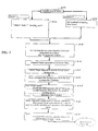
- FIG. 2 is a flow chart illustrating the steps of the method of the present invention when bringing a spare controller on line;
- FIG. 3 is a flow chart illustrating the steps of a recovery process when a repaired site controller is brought back on line;
- FIG. 4 is a flow chart illustrating the steps of database population in accordance with a method of the present invention.
- FIG. 5 is a simplified block diagram of an existing controller configuration at a typical retail fueling station
- FIG. 6 is a simplified block diagram of a first embodiment of the controller configuration of the present invention when implemented at a retail fueling station;
- FIG. 7 is a simplified block diagram of a second embodiment of the controller configuration of the present invention when implemented at a retail fueling station;
- FIG. 8 is a simplified block diagram of a third embodiment of the controller configuration of the present invention when implemented at a retail fueling station.
- FIG. 9 is a simplified block diagram of a fourth embodiment of the controller configuration of the present invention when implemented at a retail fueling station.
- the present invention is a system and method of controlling an automated fueling station.
- the invention increases the availability of automated fuel dispensers through the use of a distributed data network and a method of rapidly and efficiently backing up distributed controllers in the network.
- the invention utilizes Internet technology to reduce the site downtime by facilitating the rapid configuration and connection of a backup controller. The turnaround time is reduced to several minutes as opposed to several hours or days.
- the invention would enable the site to continue operations while a technician is dispatched to the site for troubleshooting and repair of the failed site controller.
- by distributing controllers for each dispenser at the site even if a controller fails and no backup is available, only a single dispenser is affected, not the entire site.
- All of the distributed sites in a distributed data network are connected to a central controller via, for example, the Internet or a private IP-based intranet.
- the solution includes a router, switch, hub, or other signal conversion device at each site that preferably includes an interworking function (IWF) for interfacing non-IP site devices with the IP-based data network.
- the site devices are connected to the router which in turn connects to the site controller.
- the router in turn, is connected through the IP data network to the central controller.
- the central controller is connected to a database of configuration data for each distributed site, and to a plurality of backup controllers that may be located, for example, at a help desk.
- the router may include means for detecting a failure of the site controller, or the failure may be detected by the central controller.
- the site controller may send a periodic “heartbeat” signal to the central controller indicating that it is operating normally. If the heartbeat signal stops, the central controller sends an indication to the router that the site controller has failed.
- an operator at the site may call a central help desk and report the site controller failure.
- a notice is sent to a remote help desk which includes a rack of spare site controllers and a database of site configurations.
- a spare site controller is selected and configured with the configuration of the troubled site.
- the site router at the troubled site is then reconfigured to connect the spare site controller at the remote help desk to the troubled site.
- the spare site controller then takes over as the site controller while the faulty controller is repaired or replaced.
- the invention is described in the context of the fueling industry in which a distributed network controls a plurality of automated service stations. These automated ‘self-service’ stations allow customers to dispense their own fuel, but may in fact be fully or only partially automated.
- Each station has a PC which functions as a site controller.
- Other site devices, with serial interfaces to the PC include such devices as gasoline dispensers, island card readers, and payment system dial modem interfaces.
- a failure in the PC causes the router to convert the serial interface data from the site devices to IP packets, and route the packets over the data network to a backup PC which has been configured by the central controller to replace the site PC while it is being repaired.
- FIG. 1 is a simplified block diagram of a fueling station and central control site having a plurality of virtual spare dispenser controllers illustrating one aspect of the present invention.
- distributed network 100 includes distributed site 110 , here an automated fueling facility, and central control site 160 . While for illustration they are separated by a broken line, there is no physical or distance separation requirement. (In one alternative embodiment, for example, the central control site and one of several distributed sites in the distributed network may exist at the same location, or even use the same computer.) For clarity, only a central control site and one automated fueling facility are illustrated in FIG. 1, though there could be (and usually are) numerous distributed sites, and possibly two or more control sites. Communications are accomplished over a data-communications network 150 , which is often the Internet or a wide-area network (WAN), but could be any other suitable network such as an intranet, extranet, or virtual private network (VPN).
- WAN wide-area network
- VPN virtual private network
- Fueling facility 110 includes fuel dispensers 115 and 116 , from which consumers can dispense their own fuel.
- fuel dispensers typically have an Island Card Reader (ICR) (not shown) that allows purchasers to make payment for the fuel they receive through the use of a consumer card such as, for example, a credit or debit card.
- ICR Island Card Reader
- An ICR interface 118 handles communications to and from the ICRs located on dispensers 115 and 116 so that credit or debit purchases can be authorized and the appropriate account information gathered.
- the dispensers 115 and 116 themselves communicate through dispenser interface 120 , for example, to receive authorization to dispense fuel or to report the quantity sold.
- On-site primary controller 140 is a PC or other computing facility that includes operational software and data storage capabilities in order to be able to manage site operations.
- Site operations may include not only fuel dispensing but related peripheral services as well, such as a robotic car wash.
- car-wash controller 122 is shown communicating through peripheral interface 124 .
- Communication with separate automated devices, such as a car wash, may be desirable, for example to allow payment to be made through an ICR at the dispenser, or to adjust the price charged based on other purchases already made.
- Point-of-sale (POS) terminals 125 and 126 are stations for use by a human attendant in totaling and recording sales, making change, and preforming credit card authorizations, and may be used for inventory control as well.
- POS Point-of-sale
- Hub 130 is an on-site router that directs data traffic, typically serial communications between the various on-site components. Generally, the hub 130 will receive a communication, determine where it should be sent, and effect transmission when the addressed device is ready to receive it. In addition, hub 130 is connected to data network 150 so that the distributed site 110 can communicate with the central control site 160 . Note that this connection can be permanent or ad hoc, as desired.
- the network operations controller (NOC) 165 located at central control site 160 , manages and supervises the operations of distributed site 110 and the other distributed sites in the network 100 .
- NOC network operations controller
- an owner may want to centrally manage a number of distributed fueling facilities.
- Certain operations, such as accounting and inventory control, may be efficiently done at this control center, although the specific allocation of management functions may vary according to individual requirements.
- CCAC central control accounting center
- CCAC 170 also acts as a hub or router, when necessary, to effect communications in accordance with the present invention, as explained more fully below.
- CCAC 170 handles communications between network 150 and virtual spares 171 , 172 , 173 , and 174 .
- These virtual spares are backup controllers that can be brought into use when one of the on-site primary controllers, such as on-site controller 140 , is down for maintenance.
- CCAC 170 may also be connected directly (as shown by the broken line) to NOC 165 , which in a preferred embodiment is located at the same site as the CCAC.
- the on-site controllers in distributed network 100 need not be, and very often are not, identical or identically configured.
- Software product database 180 is used for storing information related to what software is resident on each on-site controller.
- site configuration database 182 similarly maintains a record of the configuration parameters currently in use for each on-site controller in distributed network 100 .
- Databases 180 and 182 are accessible though CCAC 170 , through which they are populated and through which they are used to configure a virtual spare (as explained more fully below).
- system components of FIG. 1 are illustrated as separate physical entities, they can also be combined in one machine that is logically separated into a number of components. And as long as they can be placed in communication with the other system components as contemplated by the present invention, there is no requirement that they co-occupy the same machine, physical location, or site.
- FIG. 2 is a flow chart illustrating the steps of the method of the present invention when bringing-up a spare controller, for example virtual spare 171 shown in FIG. 1 .
- the method begins with step 200 , problem determination. This determination may occur in a variety of ways, two of which are shown in FIG. 2 .
- the problem determination includes the failure to receive a status message (sometimes called a ‘heartbeat’) that during normal operations is regularly transmitted by a properly functioning site controller (step 202 ).
- a status message sometimes called a ‘heartbeat’
- a ‘site-down’ call is received (step 204 ) at the central control site 160 , often from an attendant at the distributed site 110 .
- a system or method embodying the present invention need not include the capability to perform both scenarios, although in some circumstances both may be desirable.
- step 205 the system, and preferably NOC 165 , makes a determination of which site controller is down and whether back-up or repair is required. Normally, at this point corrective action will be initiated to recover the failed site controller, which often involves dispatching repair personnel to the site (step 210 ). Also at this time, a target machine to provide virtual-spare functionality is selected (step 215 ), such as virtual spare 171 shown in FIG. 1 . This selection is generally based on availability, but may be based on suitability for a particular situation or other factors as well. Reference is then made to the software product database 180 and the site configuration database 182 (step 220 ), to identify the software and parameters related to the down on-site controller identified in step 205 .
- the virtual spare is then prepared (step 225 ).
- the distributed site software set is loaded from software product database 180 (step 225 a ), the site configuration parameters are loaded from site configuration database 182 (step 225 b ), and the virtual spare is then warm-started (step 225 c ).
- the NOC 165 upon being notified (or otherwise determining) that a virtual spare is required, selects the appropriate spare for use according to a predetermined set of criteria, and then initiates and supervises the virtual-spare configuration process.
- some or all of these functions may be instead performed by hub 130 , or by another component (for example one dedicated for this purpose).
- the communication address tables in the on-site hub 130 must be updated so that the address of virtual spare 171 replaces that of on-site controller 140 (step 230 ).
- the address of virtual spare 171 may include the address of CACC 170 , which will receive messages sent to virtual spare 171 and route them appropriately.
- Virtual spare 171 now functions in place of the on-site controller 140 , having been configured to do so in step 225 . Note that although not shown as a step in FIG.
- hub 130 it may be necessary for hub 130 to perform a protocol conversion when routing data through network 150 instead of on-site controller 140 . Typically, this means converting serial transmissions to TCP/IP format, but could involve other procedures as well. In a preferred embodiment, an interworking function is resident on hub 130 for this purpose. Finally, the configuration now in place is tested to ensure correct functionality (step 235 ), and any necessary adjustments made (step not shown). The virtual spare 171 continues to function for on-site controller 140 until the necessary maintenance is completed and recovery begins. Note that the site controller outage (whether caused by a failure or the need for system maintenance) may be total or partial.
- the spare controller may not be required to assume all site-controller functions in order to manage operations of the on-site equipment during the outage (either because the failure was not total or because complete assumption is not necessary or desired).
- the terms “back up” and “backing up” refer to replacing some or all controller functionality according to the system and method described, and not merely to the process of making a “backup” copy of software, or of database contents (although copies of software and data may certainly be useful while practicing the invention).
- FIG. 3 is a flow chart illustrating the steps of a recovery process according to an embodiment of the present invention, where a repaired on-site controller is brought back on-line.
- the recovery process follows from process of FIG. 2 (or an equivalent method), where a virtual spare is bought in as a backup.
- the virtual system is synchronized with the third-party systems (step 310 ). For example, if virtual spare 171 has been functioning for on-site controller 140 , virtual spare 171 performs the end-of-day (EOD) synchronization that would ordinarily have been done by the controller 140 , such as balancing accounts, storing data, transmitting reports to the network operator or to third-party financial institutions.
- EOD end-of-day
- the repaired unit such as on-site controller 140 , is started-up (step 315 ). Since it has been down for a time, the repaired controller's configuration files are updated (step 320 ), as necessary. It is then ready to be placed back into operation, so the router address tables are altered to change the routing address for relevant communications from the virtual spare 171 address back to the on-site controller 140 address (step 325 ).
- step 330 To ensure that the repaired site controller can perform its normal function, its connectivity to the network is validated (step 330 ), and the functionality of the on-site controller itself is also validated (step 335 ). Once the results of this test are verified, the virtual spare 171 is returned to inventory (step 340 ), that is, made available for other tasks. The process is finished at step 350 , where the problem resolution has been achieved with a minimum of interruptions to normal system operations.
- the NOC 165 directs the process of restoring the site controller to service, this function may also be performed by hub 130 , another system component, or shared.
- FIG. 4 is a flow chart illustrating the steps of database population in accordance with a method of the present invention.
- the system and method of the present invention depend on prior creation of the appropriate database records, since by definition the rapid-and-efficient backup will be required when the site controller is unavailable and cannot provide the information needed to correctly configure a spare.
- An exception occurs in the case of a planned outage. Since it is in that case known when the site controller will be taken out of service, the virtual spare can be configured from a database created especially for the planned outage, or even directly from the still-operational site controller itself. Since premature failure of a site controller cannot be completely avoided, however, the preferred method remains the population of software product database 180 and the site configuration database 182 at the time the site is installed, or modified, as shown in FIG. 4 .
- the process of FIG. 4 begins with receiving an order for a new network of distributed sites (step 410 ). After the order is processed (step 415 ), the new site system is staged, and the software product database by site is created (step 420 ). At site installation, step 425 , where the actual hardware is put into place and connected, for example as shown by the fueling facility 110 of FIG. 1 . The installed site system is configured (step 430 ), and the site controller is then started-up and registers its configuration in the site configuration database (step 435 ).
- System upgrades are populated in like fashion.
- the distribution of the upgrade software is scheduled (step 445 ).
- the system automatically distributes the software to the site controllers and updates the software product database to reflect the new site configuration (step 450 ).
- a system review process is then initiated to review exceptions and resolve issues (step 455 ). Any resulting changes affecting site configuration are added to the site configuration database (step not shown).
- FIG. 5 is a simplified block diagram of an existing controller configuration at a typical retail fueling station having six fuel dispensers 510 - 515 .
- the six dispensers are connected through a Distribution Box (D-Box) 520 to a central CPU controller 525 .
- the D-Box is an electrical signal concentrator and converter (hardware only) used to consolidate dispenser control signals (via field wiring) into one or more serial channels.
- the D-Box provides field wiring termination, signal conversion, device isolation for maintenance and trouble shooting, and dissipation of high energy electrostatic discharges such as lightning.
- the physical interface between the D-Box and each dispenser is typically implemented with two distinct pairs of wires, one dedicated to the fuel dispenser, and the other dedicated to Island Card Reader (ICR) control. Each wire pair typically controls the fuel and payment processing for two logical fuel positions such as dispenser positions 1 and 2 .
- the dispenser and ICR physical interfaces are typically supported by Active Current Loop (30-45 ma) and RS-422/485 controlled transmitter circuits.
- the CPU controller runs application programs that provide automated fuel transactions.
- the connection between the D-Box and the CPU controller comprises a D-Link 530 and an I-Link 535 .
- the D-Link is a serial connection that enables the application programs in the controller to implement and maintain a dispenser message level protocol.
- the I-Link is a serial connection that enables the application programs to implement and maintain ICR message level protocols.
- the central CPU controller 525 is connected remotely to a Host Server 540 via an H-Link 545 .
- the Host Server provides all card processing and data capture services to the application programs running on the CPU controller 525 .
- the H-Link is typically a fiber optic cable providing an Ethernet connection between the controller and the Host Server for the purposes of consumer card authorization, transaction capture, and various administrative functions.
- the H-Link, central CPU controller, and D-Box are all single points of failure affecting all six of the dispensers.
- FIG. 6 is a simplified block diagram of a first embodiment of the controller configuration of the present invention when implemented at a retail fueling station having six fuel dispensers 610 - 615 .
- Each of the six dispensers is connected via a D-Link 620 and an I-Link 625 to one of six dedicated CPU controllers 630 - 635 .
- the D-Link is a serial connection that enables the application programs in the controller to implement and maintain a dispenser message level protocol for controlling the fueling operation of the dispenser.
- the I-Link is a serial connection that enables the application programs to implement and maintain ICR message level protocols for controlling the island card reader and accepting customer payment for the fuel. Note that each of the dedicated CPU controllers may be physically implemented within each of the fuel dispensers.
- the D-Link and I-Link connections are internal to the dispenser, and only the H-Link is managed externally.
- the H-Link may also be implemented using wireless technology, therefore reducing the external connections from the dispenser to AC power only.
- the CPU controllers may be implemented in an array of controllers at another physical location external to the dispensers. For example, multiple CPU controllers may be rack-mounted in an air-conditioned kiosk with a single monitor, keyboard and mouse connections.
- the dispenser and ICR physical interfaces are typically supported by Active Current Loop (30-45 ma) and RS-422/485 controlled transmitter circuits. These physical interfaces are not readily available for PCs, and thus are typically managed externally to the CPU controllers. In one embodiment of the present invention, the signal conversion functionality that was previously performed in the D-Box is performed in the CPU controllers.
- Each of the dedicated CPU controllers is connected to a Host Server 640 via one of a plurality of H-Links 645 .
- the H-Links may be, for example, wireless communication links or fiber optic cables providing an Ethernet connection between each of the dedicated controllers and the Host Server for the purposes of consumer card authorization, transaction capture, and various administrative functions.
- the prior art dispenser field wiring is eliminated, the D-Box is eliminated, and a plurality of H-Links and dedicated CPU controllers have replaced the single points of failure that adversely affected all of the dispensers at the site in the prior art architecture.
- an H-Link or CPU controller fails, and a backup is not available, only a single dispenser is affected.
- Each of the dedicated CPU controllers 630 - 635 is also modified to accept price file updates in order to support fuel price changes and other administrative reporting functions.
- Each of the individual CPU controllers is also remotely accessible by service personnel for purposes of system maintenance and software upgrades. Additional Ethernet and USB interfaces should provide adequate capacity for future serial port expansion.
- FIG. 7 is a simplified block diagram of a second embodiment of the controller configuration of the present invention which solves this problem by installing a Global Positioning System (GPS) receiver 650 - 655 with each CPU controller 630 - 635 .
- GPS Global Positioning System
- Each GPS receiver receives signals transmitted from at least four GPS satellites and calculates a precise location for the receiver. This location information is then sent over the H-Link 645 to the host server 640 . Thereafter, if a CPU controller fails, the physical location of the failed controller can be ascertained from the data received from the failed controller's associated GPS receiver.
- GPS Global Positioning System
- FIG. 8 is a simplified block diagram of a third embodiment of the controller configuration of the present invention when implemented at a retail fueling station having six fuel dispensers 710 - 715 .
- each of the fuel dispensers includes a Signal Converter (SC) 720 - 725 that converts the Active Current Loop and RS-422/485 controlled transmitter circuits utilized for the D-Link and I-Link signaling into an Internet Protocol (IP)-based protocol such as Transaction Control Protocol/Internet Protocol (TCP/IP).
- IP Internet Protocol
- TCP/IP Transaction Control Protocol/Internet Protocol
- Each of the dispensers then connects directly to an IP-based, connectionless packet data network 730 .
- Each of the CPU controllers 735 - 740 also connects to the IP-based network, providing inter-connectivity between any one of the dispenser controllers and any one or more of the fuel dispensers. With appropriate addressing, any of the CPU controllers can thus communicate with and control any dispenser or combination of dispensers.
- each of the CPU controllers 735 - 740 may be connected to a Host Server 745 via one of a plurality of H-Links 750 .
- the H-Links may be wireless communication links or fiber optic cables providing an Ethernet connection between each of the dedicated controllers and the Host Server for the purposes of consumer card authorization, transaction capture, and various administrative functions.
- the Host Server knows at any point in time, the status of each CPU controller, and whether each controller is currently idle or engaged in a fueling transaction. For example, the Host Server may receive periodic “heartbeat” signals from the CPU controllers, and thus may determine that a controller has failed when the heartbeat signal is not received.
- the CPU controllers may be unassigned until a customer begins a fueling transaction. At that time, an idle controller is assigned to the customer's fuel dispenser.
- each of the CPU controllers may be associated with a particular fuel dispenser, and the interconnectivity of the IP-based network 730 may be utilized to switch controllers only if a controller fails. If any CPU controller fails, the Host Server 745 may reroute the IP signaling from any other controller to the dispenser associated with the failed controller.
- the controller software in each CPU controller is capable of controlling one or all of the dispensers simultaneously. Therefore, multiple redundancy is provided through multiple on-site backup controllers.
- FIG. 9 is a simplified block diagram of a fourth embodiment of the controller configuration of the present invention when implemented at a retail fueling station having six fuel dispensers 710 - 715 .
- each of the fuel dispensers includes a Signal Converter (SC) 720 - 725 that converts the Active Current Loop and RS-422/485 controlled transmitter circuits utilized for the D-Link and I-Link signaling into an IP-based protocol such as TCP/IP.
- SC Signal Converter
- Each of the dispensers then connects directly to the IP-based packet data network 730 .
- Each of the CPU controllers 810 - 815 also connects to the IP-based network, providing inter-connectivity between any one of the dispenser controllers and any one or more of the fuel dispensers. With appropriate addressing, any of the CPU controllers can thus communicate with and control any dispenser or combination of dispensers.
- the unattended fueling station may operate without a connection to a remote host server.
- the functions performed by the remote host in other configurations are performed on site by the CPU controllers 810 - 815 .
- Each of the CPU controllers can perform consumer card authorizations and record transactions for later download.
- card authorization consumers first swipe a membership card through the ICR at the dispenser.
- the CPU controller recognizes the membership number encoded on the card from a membership card file 820 , and authorizes the sale which may be charged to a membership account.
- the customer may swipe a consumer credit or debit card through the ICR, and the CPU controller authorizes the sale based on its recognition of the membership number.
- a local consumer card status file 825 may be downloaded to a database at the fueling site from a main office 830 .
- the associated CPU controller checks the local card file to determine whether the sale should be authorized. If so, the controller activates the dispenser and records the transaction when completed.
- the dispensers may still be connected to a central control system remotely located from the fueling station.
- the central control system may include a spare controller configured to at least partially match the configuration of the CPU controllers at the fueling station. When a CPU controller fails at the station, the central control system may route communications between the spare controller and the fuel dispenser associated with the failed CPU controller.
- the present invention advantageously provides a system and method for distributing CPU controllers at a site and backing up the distributed controllers in a data network.
Abstract
Description
Claims (25)
Priority Applications (1)
| Application Number | Priority Date | Filing Date | Title |
|---|---|---|---|
| US10/138,456 US6801835B2 (en) | 2000-02-28 | 2002-05-03 | System and method for controlling an automated fueling station |
Applications Claiming Priority (3)
| Application Number | Priority Date | Filing Date | Title |
|---|---|---|---|
| US18532700P | 2000-02-28 | 2000-02-28 | |
| US09/796,664 US6725106B1 (en) | 2000-02-28 | 2001-02-28 | System and method for backing up distributed controllers in a data network |
| US10/138,456 US6801835B2 (en) | 2000-02-28 | 2002-05-03 | System and method for controlling an automated fueling station |
Related Parent Applications (1)
| Application Number | Title | Priority Date | Filing Date |
|---|---|---|---|
| US09/796,664 Continuation-In-Part US6725106B1 (en) | 2000-02-28 | 2001-02-28 | System and method for backing up distributed controllers in a data network |
Publications (2)
| Publication Number | Publication Date |
|---|---|
| US20020128988A1 US20020128988A1 (en) | 2002-09-12 |
| US6801835B2 true US6801835B2 (en) | 2004-10-05 |
Family
ID=46279145
Family Applications (1)
| Application Number | Title | Priority Date | Filing Date |
|---|---|---|---|
| US10/138,456 Expired - Fee Related US6801835B2 (en) | 2000-02-28 | 2002-05-03 | System and method for controlling an automated fueling station |
Country Status (1)
| Country | Link |
|---|---|
| US (1) | US6801835B2 (en) |
Cited By (20)
| Publication number | Priority date | Publication date | Assignee | Title |
|---|---|---|---|---|
| US20040187951A1 (en) * | 2003-03-27 | 2004-09-30 | Barker R. Keith | Method and apparatus for dispensing motor vehicle fuel at unattended locations |
| US20040204999A1 (en) * | 2003-04-10 | 2004-10-14 | Dresser, Inc. | In dispenser point-of-sale module for fuel dispensers |
| US20050240541A1 (en) * | 2002-05-28 | 2005-10-27 | Giacaman Miguel S | Multi-device control and data communication system for fuel dispensing equipment |
| US20050261839A1 (en) * | 2004-05-18 | 2005-11-24 | Shinde Ninad A | Smart substance processing device and a system and method of monitoring thereof |
| US20060139169A1 (en) * | 2004-12-13 | 2006-06-29 | Veeder-Root Company | Wireless probe system and method for a fueling environment |
| US20060271431A1 (en) * | 2005-03-31 | 2006-11-30 | Wehr Gregory J | System and method for operating one or more fuel dispensers |
| US20070106559A1 (en) * | 2003-04-10 | 2007-05-10 | Dresser, Inc. | Fuel Dispenser Commerce |
| US20070119859A1 (en) * | 2005-11-14 | 2007-05-31 | Dresser, Inc. | Fuel Dispenser Management |
| US20070152038A1 (en) * | 2005-10-31 | 2007-07-05 | David Ciancio | Combined in-store and fuel center point-of-sale system |
| US20070257109A1 (en) * | 2006-05-02 | 2007-11-08 | Johansen William Jr | Payment system with outdoor terminal |
| US20070261760A1 (en) * | 2003-04-10 | 2007-11-15 | Dresser, Inc. | Fuel Dispenser Management |
| US20070278248A1 (en) * | 2006-05-31 | 2007-12-06 | Van Vliet Scott M | Self-contained remote fueling system |
| US20080126213A1 (en) * | 2006-09-14 | 2008-05-29 | Gilbarco Inc. | Peer-to-peer data replication for off-line transactions in a retail fueling environment |
| US8020754B2 (en) | 2001-08-13 | 2011-09-20 | Jpmorgan Chase Bank, N.A. | System and method for funding a collective account by use of an electronic tag |
| US20120166343A1 (en) * | 2010-12-22 | 2012-06-28 | Giovanni Carapelli | Fuel dispensing payment system for secure evaluation of cardholder data |
| US20160086419A1 (en) * | 2012-11-16 | 2016-03-24 | Todd Goldstein | Method and device for accessing, controlling and purchasing a product through a dispenser |
| US9495822B2 (en) | 2012-10-24 | 2016-11-15 | Gilbarco Inc. | Retail fueling environment utilizing powered communication over legacy cabling |
| US9496920B2 (en) | 2011-11-16 | 2016-11-15 | Gilbarco Inc. | Fuel dispensing environment utilizing retrofit broadband communication system |
| US10155652B2 (en) | 2016-07-28 | 2018-12-18 | Gilbarco Inc. | Fuel dispensing environment utilizing fueling position availability indicator system |
| US10846146B2 (en) | 2017-08-17 | 2020-11-24 | Wiz-Tec EMS, Inc. | Bridging circuit and control system for automatic control of fluid dispensers, article dispensers, and related systems |
Families Citing this family (15)
| Publication number | Priority date | Publication date | Assignee | Title |
|---|---|---|---|---|
| BR0213621A (en) * | 2001-10-02 | 2004-09-14 | Miguel S Giacaman | Fuel Supply Pump Controller |
| US20050267673A1 (en) * | 2004-01-20 | 2005-12-01 | Varec, Inc. | Multiple fueler operations for fuel information messaging system |
| IES20040044A2 (en) * | 2004-01-23 | 2005-09-21 | January Patents Ltd | Electronic point of sale apparatus |
| US20050234569A1 (en) * | 2004-04-19 | 2005-10-20 | Hydro-Spray | Vehicle wash control system |
| US7904181B2 (en) * | 2004-06-01 | 2011-03-08 | Ils Technology Llc | Model for communication between manufacturing and enterprise levels |
| EP1621429A1 (en) * | 2004-07-27 | 2006-02-01 | Siemens VDO Trading B.V. | Fuel dispensing facilities arrangement |
| WO2007112354A1 (en) * | 2006-03-27 | 2007-10-04 | Labcoat, Ltd. | Method for modulating a drug release profile of a device |
| US8055526B2 (en) | 2006-09-08 | 2011-11-08 | Varec, Inc. | Method for the automated dispatch of fueling operations |
| AU2007358105B2 (en) * | 2007-08-28 | 2013-05-16 | January Patents Limited | An electronic point of sales vending control apparatus |
| US7949900B2 (en) * | 2008-09-19 | 2011-05-24 | International Business Machines Corporation | Autonomously configuring information systems to support mission objectives |
| US20100306072A1 (en) * | 2009-05-29 | 2010-12-02 | Bank Of America Corporation | Instant financial credit system |
| US9053503B2 (en) | 2011-04-21 | 2015-06-09 | Gilbarco, S.R.L. | Fueling environment wireless architecture |
| US10407294B2 (en) * | 2013-04-30 | 2019-09-10 | Holystone Usa, Inc. | Fuel island redundant monitoring system |
| US20150368088A1 (en) * | 2014-06-18 | 2015-12-24 | Shell Oil Company | System and method for dispensing fuel |
| WO2020117860A1 (en) * | 2018-12-03 | 2020-06-11 | Michael Derby | Virtual payment system and method for dispensing fuel |
Citations (12)
| Publication number | Priority date | Publication date | Assignee | Title |
|---|---|---|---|---|
| US3536109A (en) * | 1967-12-18 | 1970-10-27 | Standard Oil Co | Control mechanism for automatic dispensing of motor fuel |
| US3786421A (en) * | 1972-05-25 | 1974-01-15 | Atlantic Richfield Co | Automated dispensing system |
| US5327066A (en) * | 1993-05-25 | 1994-07-05 | Intellectual Property Development Associates Of Connecticut, Inc. | Methods and apparatus for dispensing a consumable energy source to a vehicle |
| US5694326A (en) * | 1996-05-08 | 1997-12-02 | Progressive International Electronics | Fuel pump - card reader control center |
| US5790410A (en) * | 1996-12-12 | 1998-08-04 | Progressive International Electronics | Fuel dispenser controller with data packet transfer command |
| US5889676A (en) * | 1996-06-03 | 1999-03-30 | Matsushita Electric Industrial Co., Ltd. | Point of sales system |
| US5980090A (en) * | 1998-02-10 | 1999-11-09 | Gilbarco., Inc. | Internet asset management system for a fuel dispensing environment |
| US6052629A (en) * | 1997-07-18 | 2000-04-18 | Gilbarco Inc. | Internet capable browser dispenser architecture |
| US6073840A (en) * | 1997-09-26 | 2000-06-13 | Gilbarco Inc. | Fuel dispensing and retail system providing for transponder prepayment |
| US6098879A (en) * | 1997-09-26 | 2000-08-08 | Gilbarco, Inc. | Fuel dispensing system providing customer preferences |
| US6264103B1 (en) * | 1998-03-10 | 2001-07-24 | Tokheim Corporation | Card processor for use in fuel dispensing equipment |
| US6390151B1 (en) * | 1998-12-22 | 2002-05-21 | Tokheim Corporation | Automated fueling system with remote service facility to operate multiple refueling stations |
-
2002
- 2002-05-03 US US10/138,456 patent/US6801835B2/en not_active Expired - Fee Related
Patent Citations (12)
| Publication number | Priority date | Publication date | Assignee | Title |
|---|---|---|---|---|
| US3536109A (en) * | 1967-12-18 | 1970-10-27 | Standard Oil Co | Control mechanism for automatic dispensing of motor fuel |
| US3786421A (en) * | 1972-05-25 | 1974-01-15 | Atlantic Richfield Co | Automated dispensing system |
| US5327066A (en) * | 1993-05-25 | 1994-07-05 | Intellectual Property Development Associates Of Connecticut, Inc. | Methods and apparatus for dispensing a consumable energy source to a vehicle |
| US5694326A (en) * | 1996-05-08 | 1997-12-02 | Progressive International Electronics | Fuel pump - card reader control center |
| US5889676A (en) * | 1996-06-03 | 1999-03-30 | Matsushita Electric Industrial Co., Ltd. | Point of sales system |
| US5790410A (en) * | 1996-12-12 | 1998-08-04 | Progressive International Electronics | Fuel dispenser controller with data packet transfer command |
| US6052629A (en) * | 1997-07-18 | 2000-04-18 | Gilbarco Inc. | Internet capable browser dispenser architecture |
| US6073840A (en) * | 1997-09-26 | 2000-06-13 | Gilbarco Inc. | Fuel dispensing and retail system providing for transponder prepayment |
| US6098879A (en) * | 1997-09-26 | 2000-08-08 | Gilbarco, Inc. | Fuel dispensing system providing customer preferences |
| US5980090A (en) * | 1998-02-10 | 1999-11-09 | Gilbarco., Inc. | Internet asset management system for a fuel dispensing environment |
| US6264103B1 (en) * | 1998-03-10 | 2001-07-24 | Tokheim Corporation | Card processor for use in fuel dispensing equipment |
| US6390151B1 (en) * | 1998-12-22 | 2002-05-21 | Tokheim Corporation | Automated fueling system with remote service facility to operate multiple refueling stations |
Cited By (37)
| Publication number | Priority date | Publication date | Assignee | Title |
|---|---|---|---|---|
| US8020754B2 (en) | 2001-08-13 | 2011-09-20 | Jpmorgan Chase Bank, N.A. | System and method for funding a collective account by use of an electronic tag |
| US10853781B2 (en) * | 2002-05-28 | 2020-12-01 | Miguel S. Giacaman | Multi-device control and data communication system for fuel dispensing equipment |
| US20050240541A1 (en) * | 2002-05-28 | 2005-10-27 | Giacaman Miguel S | Multi-device control and data communication system for fuel dispensing equipment |
| US7096895B2 (en) * | 2003-03-27 | 2006-08-29 | Barker R Keth | Method and apparatus for dispensing motor vehicle fuel at unattended locations |
| US20040187951A1 (en) * | 2003-03-27 | 2004-09-30 | Barker R. Keith | Method and apparatus for dispensing motor vehicle fuel at unattended locations |
| US10118814B2 (en) | 2003-04-10 | 2018-11-06 | Wayne Fueling Systems | Fuel dispenser management |
| US8925808B2 (en) | 2003-04-10 | 2015-01-06 | Wayne Fueling Systems Llc | Fuel dispenser commerce |
| US20070106559A1 (en) * | 2003-04-10 | 2007-05-10 | Dresser, Inc. | Fuel Dispenser Commerce |
| US10990942B2 (en) | 2003-04-10 | 2021-04-27 | Wayne Fueling Systems Llc | Fuel dispenser commerce |
| US20040204999A1 (en) * | 2003-04-10 | 2004-10-14 | Dresser, Inc. | In dispenser point-of-sale module for fuel dispensers |
| US7624042B2 (en) | 2003-04-10 | 2009-11-24 | Dresser, Inc. | In dispenser point-of-sale module for fuel dispensers |
| US9045324B2 (en) | 2003-04-10 | 2015-06-02 | Wayne Fueling Systems Llc | Fuel dispenser management |
| US10108943B2 (en) | 2003-04-10 | 2018-10-23 | Wayne Fueling Systems | Fuel dispenser commerce |
| US20070261760A1 (en) * | 2003-04-10 | 2007-11-15 | Dresser, Inc. | Fuel Dispenser Management |
| US20050261839A1 (en) * | 2004-05-18 | 2005-11-24 | Shinde Ninad A | Smart substance processing device and a system and method of monitoring thereof |
| US20060139169A1 (en) * | 2004-12-13 | 2006-06-29 | Veeder-Root Company | Wireless probe system and method for a fueling environment |
| US7561040B2 (en) | 2004-12-13 | 2009-07-14 | Veeder-Root Company | Wireless probe system and method for a fueling environment |
| US20090256700A1 (en) * | 2004-12-13 | 2009-10-15 | Veeder-Root Company | Wireless Probe System and Method For a Fueling Environment |
| US8872651B2 (en) | 2004-12-13 | 2014-10-28 | Veeder-Root Company | Wireless probe system and method for a fueling environment |
| US20060271431A1 (en) * | 2005-03-31 | 2006-11-30 | Wehr Gregory J | System and method for operating one or more fuel dispensers |
| US20070152038A1 (en) * | 2005-10-31 | 2007-07-05 | David Ciancio | Combined in-store and fuel center point-of-sale system |
| US8123125B2 (en) | 2005-10-31 | 2012-02-28 | The Kroger Co. | Combined in-store and fuel center point-of-sale system |
| US20090150244A1 (en) * | 2005-10-31 | 2009-06-11 | David Ciancio | Combined in-store and fuel center point-of-sale system |
| US7469826B2 (en) * | 2005-10-31 | 2008-12-30 | The Kroger Co. | Combined in-store and fuel center point-of-sale system |
| US20070119859A1 (en) * | 2005-11-14 | 2007-05-31 | Dresser, Inc. | Fuel Dispenser Management |
| US20070257109A1 (en) * | 2006-05-02 | 2007-11-08 | Johansen William Jr | Payment system with outdoor terminal |
| US20070278248A1 (en) * | 2006-05-31 | 2007-12-06 | Van Vliet Scott M | Self-contained remote fueling system |
| US20080126213A1 (en) * | 2006-09-14 | 2008-05-29 | Gilbarco Inc. | Peer-to-peer data replication for off-line transactions in a retail fueling environment |
| US10657524B2 (en) | 2010-12-22 | 2020-05-19 | Gilbarco Inc. | Fuel dispensing payment system for secure evaluation of cardholder data |
| US20120166343A1 (en) * | 2010-12-22 | 2012-06-28 | Giovanni Carapelli | Fuel dispensing payment system for secure evaluation of cardholder data |
| US9262760B2 (en) * | 2010-12-22 | 2016-02-16 | Gilbarco Inc. | Fuel dispensing payment system for secure evaluation of cardholder data |
| US9496920B2 (en) | 2011-11-16 | 2016-11-15 | Gilbarco Inc. | Fuel dispensing environment utilizing retrofit broadband communication system |
| US9495822B2 (en) | 2012-10-24 | 2016-11-15 | Gilbarco Inc. | Retail fueling environment utilizing powered communication over legacy cabling |
| US9959530B2 (en) * | 2012-11-16 | 2018-05-01 | Scanx, Llc | Method and device for accessing, controlling and purchasing a product through a dispenser |
| US20160086419A1 (en) * | 2012-11-16 | 2016-03-24 | Todd Goldstein | Method and device for accessing, controlling and purchasing a product through a dispenser |
| US10155652B2 (en) | 2016-07-28 | 2018-12-18 | Gilbarco Inc. | Fuel dispensing environment utilizing fueling position availability indicator system |
| US10846146B2 (en) | 2017-08-17 | 2020-11-24 | Wiz-Tec EMS, Inc. | Bridging circuit and control system for automatic control of fluid dispensers, article dispensers, and related systems |
Also Published As
| Publication number | Publication date |
|---|---|
| US20020128988A1 (en) | 2002-09-12 |
Similar Documents
| Publication | Publication Date | Title |
|---|---|---|
| US6801835B2 (en) | System and method for controlling an automated fueling station | |
| US6725106B1 (en) | System and method for backing up distributed controllers in a data network | |
| CN1332538C (en) | Distributed on-line data communications system and method | |
| JP3810139B2 (en) | Failure detection method for electronic price label system | |
| US8925808B2 (en) | Fuel dispenser commerce | |
| US8998082B2 (en) | Multimedia system and methods for controlling vending machines | |
| US7938321B2 (en) | Fuel dispenser management | |
| US6138249A (en) | Method and apparatus for monitoring computer systems during manufacturing, testing and in the field | |
| US8296753B2 (en) | Upgrade service system | |
| US6308111B1 (en) | Information collecting system | |
| US20010034567A1 (en) | Remote management of retail petroleum equipment | |
| US20070100696A1 (en) | Multimedia system and method for controlling vending machines | |
| CA2629523A1 (en) | Fuel dispenser management | |
| US6009538A (en) | System and method of reporting a status of another system through an electronic price label system | |
| US10118814B2 (en) | Fuel dispenser management | |
| US20130290407A1 (en) | Method and system for facilitating non-interruptive transactions | |
| JPH08165813A (en) | Remote control system for parking garage apparatus | |
| CN115273354A (en) | Bank self-service equipment management method and system and computer equipment | |
| WO1991007725A2 (en) | Point of sale system | |
| RU2703674C1 (en) | Control device, control and fiscal control of vending machines | |
| KR100322910B1 (en) | Method and appratus for banking-network | |
| JP2002109632A (en) | Automatic teller machine system for plural banks | |
| JP3762549B2 (en) | Game card system failure processing method and game card system | |
| US20080065428A1 (en) | Automated Campground System | |
| JP6852829B1 (en) | Route management system, route management method and program |
Legal Events
| Date | Code | Title | Description |
|---|---|---|---|
| AS | Assignment |
Owner name: AUTOGAS SYSTEMS, INC., TEXAS Free format text: ASSIGNMENT OF ASSIGNORS INTEREST;ASSIGNORS:COVINGTON, STEVE;ASHBY, DAVID;REEL/FRAME:012872/0452 Effective date: 20020502 |
|
| AS | Assignment |
Owner name: CONOCOPHILLIPS COMPANY, TEXAS Free format text: CONSENT, AGREEMENT, AND WAIVER;ASSIGNOR:NICHOLSON, G. RANDY;REEL/FRAME:014277/0334 Effective date: 20030605 Owner name: AUTO-GAS SYSTEMS, INC., TEXAS Free format text: CONSENT, AGREEMENT, AND WAIVER;ASSIGNOR:NICHOLSON, G. RANDY;REEL/FRAME:014277/0334 Effective date: 20030605 |
|
| FEPP | Fee payment procedure |
Free format text: PAT HOLDER NO LONGER CLAIMS SMALL ENTITY STATUS, ENTITY STATUS SET TO UNDISCOUNTED (ORIGINAL EVENT CODE: STOL); ENTITY STATUS OF PATENT OWNER: LARGE ENTITY |
|
| FPAY | Fee payment |
Year of fee payment: 4 |
|
| AS | Assignment |
Owner name: NICHOLSON, G. RANDY, TEXAS Free format text: TERMINATION OF CONSENT, AGREEMENT, AND WAIVER;ASSIGNORS:CONOCOPHILLIPS COMPANY;AUTO-GAS SYSTEMS, INC.;REEL/FRAME:021411/0767;SIGNING DATES FROM 20080307 TO 20080310 |
|
| AS | Assignment |
Owner name: ALTAMETRICS AUTOGAS, LLC, CALIFORNIA Free format text: ASSIGNMENT OF ASSIGNORS INTEREST;ASSIGNOR:AUTO-GAS SYSTEMS, INC;REEL/FRAME:023044/0884 Effective date: 20090331 |
|
| FEPP | Fee payment procedure |
Free format text: PETITION RELATED TO MAINTENANCE FEES GRANTED (ORIGINAL EVENT CODE: PMFG); ENTITY STATUS OF PATENT OWNER: LARGE ENTITY Free format text: PETITION RELATED TO MAINTENANCE FEES FILED (ORIGINAL EVENT CODE: PMFP); ENTITY STATUS OF PATENT OWNER: LARGE ENTITY |
|
| REMI | Maintenance fee reminder mailed | ||
| PRDP | Patent reinstated due to the acceptance of a late maintenance fee |
Effective date: 20121009 |
|
| FPAY | Fee payment |
Year of fee payment: 8 |
|
| SULP | Surcharge for late payment | ||
| REMI | Maintenance fee reminder mailed | ||
| LAPS | Lapse for failure to pay maintenance fees | ||
| STCH | Information on status: patent discontinuation |
Free format text: PATENT EXPIRED DUE TO NONPAYMENT OF MAINTENANCE FEES UNDER 37 CFR 1.362 |
|
| FP | Lapsed due to failure to pay maintenance fee |
Effective date: 20161005 |