US6785700B2 - Implementation of wavelet functions in hardware - Google Patents
Implementation of wavelet functions in hardware Download PDFInfo
- Publication number
- US6785700B2 US6785700B2 US09/736,891 US73689100A US6785700B2 US 6785700 B2 US6785700 B2 US 6785700B2 US 73689100 A US73689100 A US 73689100A US 6785700 B2 US6785700 B2 US 6785700B2
- Authority
- US
- United States
- Prior art keywords
- multiplier
- architecture
- wavelet
- filter
- stage
- Prior art date
- Legal status (The legal status is an assumption and is not a legal conclusion. Google has not performed a legal analysis and makes no representation as to the accuracy of the status listed.)
- Expired - Lifetime, expires
Links
Images


Classifications
-
- G—PHYSICS
- G06—COMPUTING; CALCULATING OR COUNTING
- G06F—ELECTRIC DIGITAL DATA PROCESSING
- G06F17/00—Digital computing or data processing equipment or methods, specially adapted for specific functions
- G06F17/10—Complex mathematical operations
- G06F17/14—Fourier, Walsh or analogous domain transformations, e.g. Laplace, Hilbert, Karhunen-Loeve, transforms
- G06F17/148—Wavelet transforms
Definitions
- This invention relates to implementation of wavelet analysis in hardware.
- Wavelet analysis provides a powerful method for analysing time-varying signals.
- wavelet analysis can be considered as being related to Fourier analysis.
- Fourier analysis can transform a signal varying in amplitude in the time domain into a signal that varies in the frequency domain.
- Fourier analysis thereby provides an indication of the frequency content of the signal.
- Fourier analysis uses sine and cosine as basis functions, whereby the transform is indicative of the sine and cosine content of the original signal across a frequency range.
- a Fourier transform cannot be used to analyse discrete time segments in a continuous signal. For example, if the signal is a continuous speech signal, a Fourier transform cannot be used to perform a frequency analysis on a time-limited segment such as a single word within the speech signal.
- Wavelet analysis has been evolved as a more powerful analysis tool. Two features of wavelet functions contribute in particular to their power.
- wavelet analysis can be performed over a part of the original signal that is limited in time. Moreover, the time over which the analysis operates can be varied simply by making relatively small changes to the analysis procedure. This allows the analysis to be tuned to give results that are more accurate in either their resolution in frequency or in time, as best suits the objective of the analysis (although, it should be noted, that an increase in accuracy in one domain will inevitably result in a decrease in accuracy in the other).
- wavelet analysis can be based on an arbitrary basis function (referred to as a “mother wavelet”. It might be used to express the frequency content of a time-varying signal in terms of its frequency-domain content of, for example, sine and cosine waves, square waves, triangular waves, or any other arbitrary wave shape.
- the basis functions can be chosen to give the most useful result based upon the content and nature of the original function and upon the result that is being sought in performing the analysis.
- CWT continuous wavelet transform
- the wavelet transform performs a decomposition of the signal x(t) into a weighted set of basis functions h(t), which are typically time-limited, finite energy signals that oscillate like waves (hence the term “wavelets”).
- this transform is complex, and consumes a considerable amount of computer power if it is to be performed by a computer executing a software program.
- the coefficients c j,k describe the detailed components in the signal and the coefficients s j,k refer to the approximation components in the signal.
- the transfer functions h(n) and g(n) in this equation represent the coefficients of the high-pass and the low-pass filters and are derived from the wavelet function and the inverse (scaling) function respectively.
- the low-pass filtered and downsampled output of each stage is fed forward to the following stage, which gives a successively reduced time resolution and increased frequency resolution after each stage. Several stages can therefore be cascaded to provide transform outputs at several levels of resolution.
- Wavelet packet decomposition is an important development of wavelet analysis.
- the principle behind these decompositions is to selectively choose the basis function (mother wavelet) and the frequency bands to be decomposed.
- This basic structure of hardware for performing wavelet packet decomposition is sown in FIG. 12 . Improved results in the area of speech and image coding, as well as signal detection and identification, have been reported using this kind of wavelet analysis.
- a hardware implementation of a DWT is most typically based upon the filter bank arrangement defined in Equation 2.
- a typical hardware implementation of such a three-level DWT is shown schematically in FIG. 1 .
- 110 ′, 110 ′′ and 110 ′′′ represent, respectively, a low-pass filter of the first, second and third stages
- 112 ′, 112 ′′ and 112 ′′′ represent, respectively, a high-pass filter of the first, second and third stages
- 114 ′, 114 ′′ and 114 ′′′ represent, respectively, downsamplers of the first, second and third stages.
- Each of the filters 110 , 112 of the circuit shown in FIG. 1 has a general form shown in FIG.
- a multiplier 210 comprising, in each of a plurality of stages, a multiplier 210 , a delay line 212 and an adder 214 .
- the characteristics of such a filter is determined by a set of coefficients C 1 . . . Cn applied respectively to each of the multipliers. Variation of the values of these coefficients, therefore allows the designer to control the characteristics of the wavelet transform operation.
- each multiplier 210 represents a considerable demand upon resources.
- An aim of this invention is to provide a design method for implementing hardware capable of performing DWT operations.
- its aim is to provide such a method that is versatile and easy to use, and that produces a hardware design that is efficient in its use of components and in the area of silicon that it occupies.
- the invention provide an implementation for wavelet transforms in hardware that possesses advantageous architectural arrangements as well as flexibility in wavelet choice, levels of decomposition and the word lengths.
- the inventors have realised that the downsampling that occurs at each stage means that, in conventional designs, the circuits typically operate at less that maximum capacity.
- each alternate output from the filters is discarded.
- the input bandwidth at subsequent stage is successively halved, giving rise to additional excess capacity in typical systems in which each stage operates at an identical clock frequency.
- each wavelet filter Since the output of each wavelet filter is downsampled by a factor of two, the alternate odd and even index values produced from the filter are discarded.
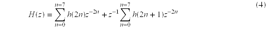
- the bi-phase decomposition of wavelet filters can be obtained by observing the output sequence. This allows the impulse response h lp (n) to be written in the form of even and odd order coefficients.
- the invention provides an architecture component for use in performing a wavelet transform of a sampled signal, the component including a multiplier, and a multiplexor to multiplex a number n of filter coefficients onto the multiplier, in which the multiplier processes n consecutive samples with consecutive coefficients, successive multiplier outputs being stored for subsequent processing to generate an output of the filter after every n samples.
- such a component can serve the same purpose as a filter and a downsampler (for example, as shown at 120 in FIG. 1 ), this being achieved with a significantly smaller number of components than is possible with a conventional configuration.
- Architectures embodying the invention process data at the same rate as a full-length direct-form filter but each multiplier uses a different coefficient multiplier value ‘a n ’ (the coefficients) and multiplicand value ‘x(n)’ (even or odd sample) in each processing cycle. Each filter generates output only when both the even and odd index samples have been processed.
- Wavelet transforms to which the invention may be applied include discrete wavelet transforms and wavelet packet decomposition.
- the result from the odd index samples is temporarily stored in a memory and it is added to the result from even index samples to generate a complete filtered and decimated output.
- an architecture component embodying the invention comprises a plurality of multipliers and associated multiplexors.
- the subsequent processing may include generating an output by summing sequential multiplier n samples.
- n may be equal to 2.
- An architecture component embodying the invention may have a number m of processing stages, each stage including a multiplier.
- sample data may be conveyed from each processing stage to a subsequent processing stage with a delay of n times a sampling period of the signal.
- such embodiments may include a chain of n buffers through which data is conveyed from each stage to a subsequent stage.
- Embodiments of the invention may further include a buffering stage in which an output value from each processing stage can be stored.
- a summing stage may be provided that is operative to sum the values stored in the buffering stage to produce an output for every n samples received.
- an architecture component embodying the invention may further comprise a multiplexor operative to present each sample to a multiplier a plurality of times for multiplication by a plurality of coefficients.
- the filter operation performed by the architecture component may be a low-pass filter or a high-pass filter operation.
- the (or each) multiplier in embodiments of the invention may be constituted by separate multiplier units or may be embodied within a MAC unit.
- Architecture components embodying the first aspect of the invention are most typically incorporated into an architecture for performing a discrete wavelet transform of a sampled signal.
- the invention provides such an architecture from a second of its aspects.
- such an architecture may comprise an architecture component configured to operate as a low-pass filter followed by a downsampling connected in parallel with an architecture component configured to operate as a high-pass filter followed by a downsampling.
- Such an architecture may also comprise a plurality of series-connected architecture components of the invention's first aspect.
- the invention provides a core for incorporation into an integrated circuit for implementing a wavelet transform, the core having an architecture according to any preceding claim.
- a core can be used as a “plug in” component in the construction of a wide range of complete electronic systems.
- the invention provides an architecture component for use in performing a wavelet transform, the architecture implementing the function of an n-tap filter followed by a downsampler, the architecture including a number of multipliers less than n, and a multiplexor for applying to the multiplier a plurality of multiplier coefficients, whereby successive data samples are processed by the multiplier using alternative filter coefficients multiplexed onto the multiplier.
- embodiments of this aspect of the invention may have n/2 multipliers.
- each multiplier acts upon sequential data samples with alternative filter coefficients.
- n 2
- two filter coefficients for each multiplier may be applied to the multiplier alternately.
- such an architecture component may be configured to multiply each sample by a total of n/2 coefficients. These multiplications may be carried out by a single multiplier (spaced in time, typically by an integer multiple of the sample period), or may be carried out by a plurality of multipliers, or both.
- time-interleaved approach is not only attractive in terms of hardware implementation of wavelet transforms, but also readily lends itself to parameterisation and is thus suitable for rapid design and synthesis. Attention here is focused mainly on high throughput applications and consequently a bit-parallel, word-serial filter implementation has been assumed. However the basic architecture can be simply extended to create silicon generators in which other word formats, such as bit-serial or digit-serial data streams are used. This allows flexibility across applications in trading silicon area with performance specifications.
- the invention provides a method for defining an architecture for performing a discrete wavelet transform of a sampled signal in which the wavelet transform is defined in terms of a plurality of numeric parameters. These parameters may specify one of more of the following: the choice of wavelet function; the input word length; the output word length; the rounding or truncation required; additional bits to prevent adder over-flow; and the amount of folding within the architecture.
- a method of this aspect if the invention may define the architecture in a hardware definition language such as VHDL, Verilog etc., a netlist format such as edif, xnf, etc., an ASIC or FPGA layout or a combination of any of the above, amongst others.
- a hardware definition language such as VHDL, Verilog etc.
- a netlist format such as edif, xnf, etc.
- an ASIC or FPGA layout or a combination of any of the above, amongst others.
- the invention provides a method for defining an architecture component for performing a wavelet transform, the definition including generating a list of generic parameters and ports for the component, connecting the delay line to the multipliers and appropriate coefficients to the multiplier through a multiplexor.
- Such a method may further comprise one or more of the following steps: connecting an adder to the output of the multiplier; generating delay line taps; generating MAC units required; generating an adder and buffer memory and a latch; or generating interconnections within the architecture.
- FIG. 1 is a block diagram of a typical hardware implementation of a three-level discrete wavelet transform, and has already been discussed;
- FIG. 2 is a block diagram of a filter being a component of the implementation of FIG. 1;
- FIG. 3 illustrates an implementation of a time-interleaved N-tap wavelet filter being a component of an architecture embodiment of the invention for performing a discrete wavelet transform
- FIG. 4 shows an alternative implementation of a time-interleaved N-tap wavelet filter being a component of an embodiment of the invention
- FIG. 5 is a further implementation of a time-interleaved N-tap wavelet filter being a component of an embodiment of the invention
- FIG. 6 a is a diagram of pipelining in the filter of FIG. 5;
- FIG. 6 b is a timing diagram of the filter of FIG. 5;
- FIG. 7 is an initial floor plan using a hierarchical placement for a silicon chip embodying the invention.
- FIG. 8 shows an implementation of a Daubechies 4 (8-taps) filter with no folding
- FIG. 9 shows an implementation of a Daubechies 4 (8-taps) filter with a folding factor of 2;
- FIG. 10 shows an implementation of a Daubechies 4 (8-taps) filter with a folding factor of 4;
- FIG. 11 is a graph of FPGA resource utilisation against folding factor for a wavelet filter
- FIG. 12 is a block diagram of a typical hardware implementation of a two-level wavelet packet transform, and has already been discussed;
- FIG. 13 is a diagram of an implementation of an architecture for use in wavelet transform or wavelet packet transform.
- FIG. 14 illustrates the hierarchy of parameters used to describe an architecture embodying the invention.
- each of the filters and downsamplers shown in FIG. 1 (or FIG. 12) at 120 is replaced with a combined filter and downsampler architecture component employing a so-called “folded architecture”.
- This embodiment implements a wavelet filter that implements an 8-tap low-pass wavelet analysis filter of the class known as ‘Daubechies 4’.
- a single stage of wavelet decomposition consists of a low-pass filter and a high-pass filter. Both are followed by a decimation stage.
- a bi-phase decomposition of wavelet filters can be obtained by observing the output sequence, and considering the effect of discarding results on the output of the filter as a whole. This allows the impulse response h lp (n) to be written in the form of even and odd order coefficients.
- the data is processed at the same rate as a full-length direct-form filter.
- each multiplier uses a different coefficient multiplier value ‘a n ’ associated with h(n) (the coefficients) and multiplicand value ‘x(n)’ for even and odd samples in each processing cycle.
- two different values of a n and x(n) are multiplexed onto each multiplier for odd and even samples respectively, and the result is only output when both the even and odd index samples have been processed.
- the result from the odd index samples is temporarily stored in a memory and it is added to the result from even index samples to generate a complete filtered and decimated output.
- time-interleaved coefficients for the multipliers and an accumulator in the output an approximate 50% reduction in the number of multipliers over a direct-form finite impulse response (FIR) filter structure is achieved. This interleaving of filter coefficients is illustrated in FIG. 3 .
- FIG. 3 there is shown an N-tap wavelet filter that carries out a low-pass filtering and downsampling operation.
- the filter comprises N/2 stages, each of which includes a multiplier 310 1 - 310 n , Each multiplier has its a multiplicand input connected to a respective connection point 312 1 - 312 N/2 on a data input line 314 . Between successive connection points 312 , there are two data delay buffers 316 1 - 316 N ⁇ 2 , all such buffers being controlled by a common data advance clock line 318 that operates in time with arrival of the data samples.
- the multiplicand input of each of the multipliers receives data from an output of a respective multiplexor 320 1 - 320 N/2 .
- Each multiplexor 320 has two inputs, either one of which is connected to the output. Filter coefficients are applied to the outputs, coefficients a 1 and a 2 being applied to the first multiplexor 320 1 , up to coefficients a N ⁇ 1 and a N being applied to the N/2th multiplexor 320 N/2 .
- Each multiplexor is configured to exchange which one of its inputs is connected to its output at each cycle of the clock line.
- each multiplier is fed to a data output line 322 , with successive outputs being added by adders 324 1 - 324 N ⁇ 1 .
- the output data line 322 supplies data that includes the sum of all stages of the filter to a first input of an adder 326 and a data buffer 328 , the buffer being configured to store data at each alternate clock cycle.
- the buffer 328 output is connected to a second input of the adder 326 .
- the output value of the filter is derived from the output value of the adder 326 . This value is stored in an output buffer 330 , the output value being updated every two clock cycles.
- the operation of this time-interleaved circuit can be explained as follows.
- the first sample arrives on the data input line 314 at time t 0 to find the first coefficient set a 0 , a 2 , a 4 , . . . a n-1 respectively available at each of the multipliers 310 .
- the output value a 0 x(0) is calculated by the first multiplier 3101 and passed to the data output line 322 to provide the first output.
- the second (odd) sample arrives at time t 1 to encounter the coefficient values a 1 , a 3 , a 5 . . . a n ,. Meanwhile, the previous input x(0) moves forward through one delay 316 and hence it is not operated by any multiplier.
- the output value alx(1) is calculated and this is stored in the buffer 328 .
- x(0) has advanced to the next multiplier 310 2 .
- the output value a 0 x(2)+a 2 x(0) is therefore produced and added to the value a 1 x(1) which was calculated in the previous odd cycle. This represents the second downsampled output value.
- the process continues to give a downsampled and filtered output.
- the same multipliers and adders are used to process two consecutive data samples.
- this arrangement can further optimise the use of hardware by sharing the same delay line between the two filters in the filter bank, shown in FIG. 13 .
- the un-folded wavelet filter architecture shown in FIG. 3 operates at a data throughput rate of T MHz.
- T the maximum input-data arrival rate
- the hardware is operating at only 50% of its capacity.
- FIG. 4 An optimisation of the filter circuit of FIG. 3 for these operating conditions is shown in FIG. 4 .
- a saving in hardware can be achieved by multiplexing the operation of four multiplication operations on two multipliers 410 , 412 .
- the individual components in the filter i.e. the multiplier, adder etc.
- the partial products from each of the multipliers 410 , 412 are individually stored in latches 414 . . . 420 and added by adders 424 . . . 430 to produce a final filter output at an output latch 430 .
- both inputs to each multiplier 410 , 412 are multiplexed.
- the multiplier input is multiplexed to receive an input from an input side of a delay line and an output side of a delay line.
- the same samples are presented to the input of each multiplier two times, spaced in time by twice the sampling period.
- the sample is presented to the multiplier, it is multiplied by a different multiplier coefficient.
- FIG. 5 This architecture employs a MAC unit 510 to facilitate the operation over a variable range of folding requirements.
- An output block 512 in FIG. 5 comprises two latches (buffers) 514 , 516 , in forward and feedback paths respectively, and a pipelined adder 518 that holds the calculation for odd order and adds it with the output of even order to produce the final result.
- This arrangement is designed to facilitate control and synchronisation over multiple folding factors. It has been found that hardware sharing in this wavelet filter architecture embodying the invention may lead to a trade-off between speed, area and power requirements while retaining the architectural attributes within the scope of this invention.
- embodiments of the invention further provide a parameterized generator for wavelet transform architectures, based upon the architectures illustrated in FIGS. 4 and 5. Such a generator allows a designer to produce wavelet transform architectures to perform as required simply by selecting an appropriate parameter set.
- the folded architecture of this embodiment uses an interconnection algorithm to connect a delay line with an appropriate multiplier-accumulator (MAC) unit and with output blocks.
- MAC multiplier-accumulator
- a pipelined Wallace tree MAC unit was employed from a predefined synthesisable library.
- a coefficient allocation method allows a designer to select a wavelet function and appropriate wordlengths at the time of instantiation through generic specifications only.
- the control circuit in this architecture is based on pipelining at three stages, as shown in FIG. 6 a .
- the timing sequence corresponding to a folding factor of one is illustrated in FIG. 6 b.
- the timing signals are under the control of the Counter signal that counts from 0 to (6F ⁇ 1), where F is the amount of folding.
- F is the amount of folding.
- a new data value is input every (3F ⁇ 1) clock cycles and an output is produced at every (6F ⁇ 1) clock cycles.
- the signal Store is used to control accumulation and the signal.
- the signal Output prompts the completion of a processing cycle.
- the Even_Odd signal in combination with the Counter signal, is used to control the connection of appropriate coefficients to the multiplier.
- a further embodiment of the invention resides in a silicon chip capable of performing three-level discrete wavelet transform using a Daubechies 8-tap wavelet function. This is based on the use of folded DWT cores having an architecture as described above. The wordlength allocation and other resulting measures are given in Table 2, below. The total number of gates required in this case is around 36K. The power consumption of this embodiment at 100 MHz clock rate is around 650 mW in 0.35 ⁇ technology. The initial floor plan of this embodiment, using a hierarchical placement, is shown in FIG. 7 .
- a folded wavelet core instantiated with a folding factor of F/2 would be exactly half the size of a similar core instantiated with a folding factor F.
- the silicon area utilisation in Table 2 shows that the actual area required at T/2 throughput is about 85% of that of an unfolded first stage. The reduction in area, as well as the number of gates, results in a corresponding decrease in power consumption. Similarly, other wavelet functions can be favourably compared.
- the scheme developed here allows flexible design trade-offs to be easily applied and analysed through generic parameters. Similarly, the area corresponding to T/4 throughput is 60% of the first stage. There are two reasons for this:
- the wordlength grows as the results pass through various filtering stages
- a folding factor of 4 appears to be a typical advantageous upper limit for these kind of wavelet transform architectures, although the invention is not limited to such a range of folding factors. Any further increase in folding for example, if the aim were be to provide a digit-serial operation, could result in more FPGA resources being allocated to multiplexing overhead than the actual circuit. Such embodiments may therefore be unpractical.
- this embodiment of the invention has as one of its advantages the flexibility that allows a designer to tailor area, power and speed specifications of the core through a generic parameter only. A number of further parameters allow the designer to tailor speed and area performance in a variety of possible combinations.
- One particular class of embodiments implement the invention through the use of parameterized wavelet cores. These offer many significant advantages over known implementations. The first and most important is the possibility to choose the wavelet function at the time of core instantiation. The second is the fact that the design of embedded control for these cores allows them to be cascaded in any fashion to generate an arbitrary time-frequency tiling. The appropriate wordlengths and quantisation for any decomposition tree can also be discreetly specified.
- the values stored in delay lines are multiplied by coefficients and added to produce a filtered output.
- the word length of the final filtering result is bound to be more than the word length of either the input sample or the coefficient.
- a number of filtering stages are cascaded. As a typical example, starting with 8 bits input data samples, can produce over 24 bits wavelet output after a three level wavelet transform. This puts excessive load on silicon area requirements as bigger adder, multiplier and delay elements will be required to process bigger word lengths. Practically, not all of the word's length is important because it can contain leading zeros or the result can be rounded. Desired accuracy requirements from result can be less stringent as well.
- This embodiment of the invention has these word lengths assigned as generic parameters for each stage of wavelet filter bank. Thus they can be easily and accurately specified so that the most efficient hardware for desired specs is produced.
- the MAC level folded wavelet transform architecture where the folding factor is under the control of a generic parameter is an important feature of preferred embodiments of the invention.
- the basis of the folded architecture used is an efficient implementation of a generic wavelet filter.
- This architecture has an embedded accumulator and a control circuit which make it conducive to multi-rate filter bank style implementations.
- the invention can further be embodied in many alternative structures that are not actual hardware but, instead, are representative of hardware.
- it may be embodied in any hardware description language that supports generic parameter specification, can be used to describe the methodology developed.
- the method can also be used for the design and implementation of any FIR filter for use in digital signal processing.
- wavelet packet decomposition includes a plurality of filtering and downsampling stages. Clearly, these may be replaced by architecture components embodying the invention to gain the advantages of the invention in wavelet packet decomposition architectures.
- FIG. 13 An advantageous configuration for such an implementation is shown in FIG. 13 .
- Each of the high-pass and low-pass stages 1310 , 1312 are configured in a manner similar to that shown in FIG. 3, discussed above. However, in order to minimise the component used, the delay line 1314 is shared between the two filter elements.
- the scalable hardware architecture described has could be captured in a hardware definition language such as VHDL. This facilitates the modular design methodology by allowing replication of smaller processing blocks. However, there is no direct mechanism in this language to acquire the wavelet coefficients from a high level description. In addition, the coefficients cannot be supplied at the time of instantiation because only integers are permitted as generic parameters.
- MATLAB (r.t.m) code is used to generate a text file containing the coefficients for any desired wavelet.
- the use of a numerical package offers a substantially unlimited range of possibilities regarding the choice and future development of wavelets.
- the text file containing real-number coefficients is then converted to 2's complement format at 16-bit resolution using VHDL code.
- the required wordlength specified in the generic description is chosen at the time of instantiation.
- Each wavelet is identified by a separate index that is specified using generics to access those coefficients. Addition of a new wavelet is simple and involves repeating these steps.
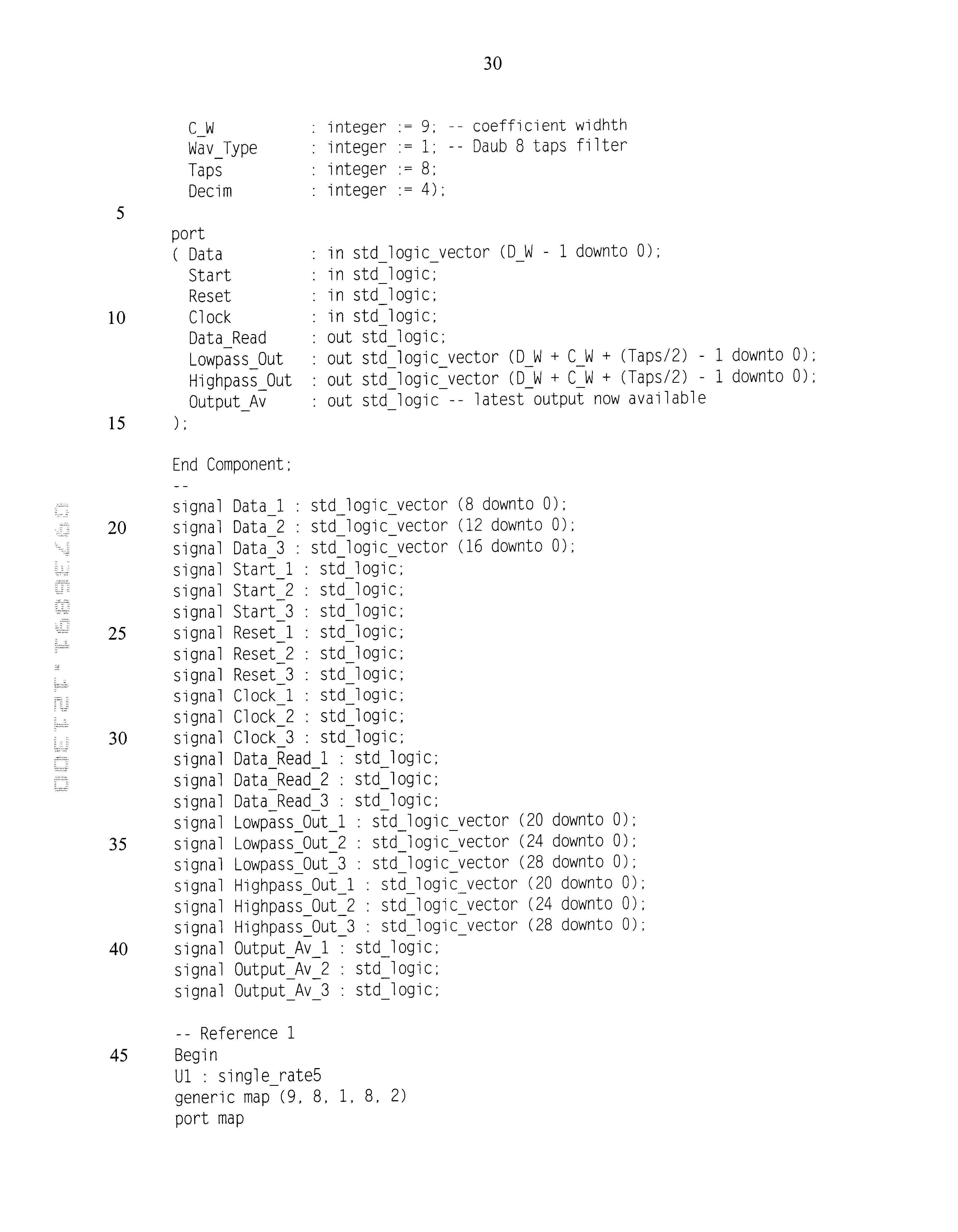
- the code in listing 1 demonstrates the implementation of the invention in a practical design of a three-level discrete wavelet transform.
- the code is written in VHDL hardware description language and follows its syntax. Appropriate signals for connecting the outputs of one stage to the input of the next are defined. The word lengths of these signals are truncated as per requirements.
- the invention is instantiated as a component with appropriate generic parameters for each stage of wavelet transform. The resulting design produced is shown in FIG. 7 .
- the code in listing 2 below (single_rate5.vhd) describes the central component of embodiments of the invention.
- the component has two main parts;
- the third part of the code represents the control circuit. This controls the sequencing of appropriate inputs to the multiplier and reading the input as well as providing the output.
- the hierarchy of parameters used within the parameterisation scheme is shown in FIG. 14 .
- Table 4 shows some of the entries in the coefficients package. The location of filter coefficients in the VHDL package is purely arbitrary.
- the filter type is set to a Daubechies 8-tap filter.
- this parameter is used to find the coefficients and loads them in the design in an array.
- the elements of this array, as shown in Listing 2 are then connected to the multipliers.
- these connections are time-multiplexed, meaning they connect to a reduced number of multipliers (e.g. 8 coefficients folded onto one multiplier) at different times under the control of control signals.
- Data Word length 8: This parameter sets the width of the delay line and one input of the multiplier to the value specified, i.e. 8, 12, 16 or whatever.
- the parameters C_W and D_W are then used to automatically determine the width of the multiplier or MAC to be employed in the circuit.
- the architecture description includes a list of any components that will be used in this design along with the list of signals used to interconnect components and other variables.
- the Begin statement starts the description of the architecture of this three-level wavelet transform design.
- U 1 , U 2 and U 3 are the instance names of three single_rate5 blocks that have been used in the design.
- the lines generic map(, . . . , . . . , . . . ) indicate the generic parameters that were used to specify wavelet type and word lengths for each stage along with folding parameter.
- Listing 2 Defines the design of component single_rate5.
- the entity definition now includes the list of generic parameters and ports for the single_rate5 component.
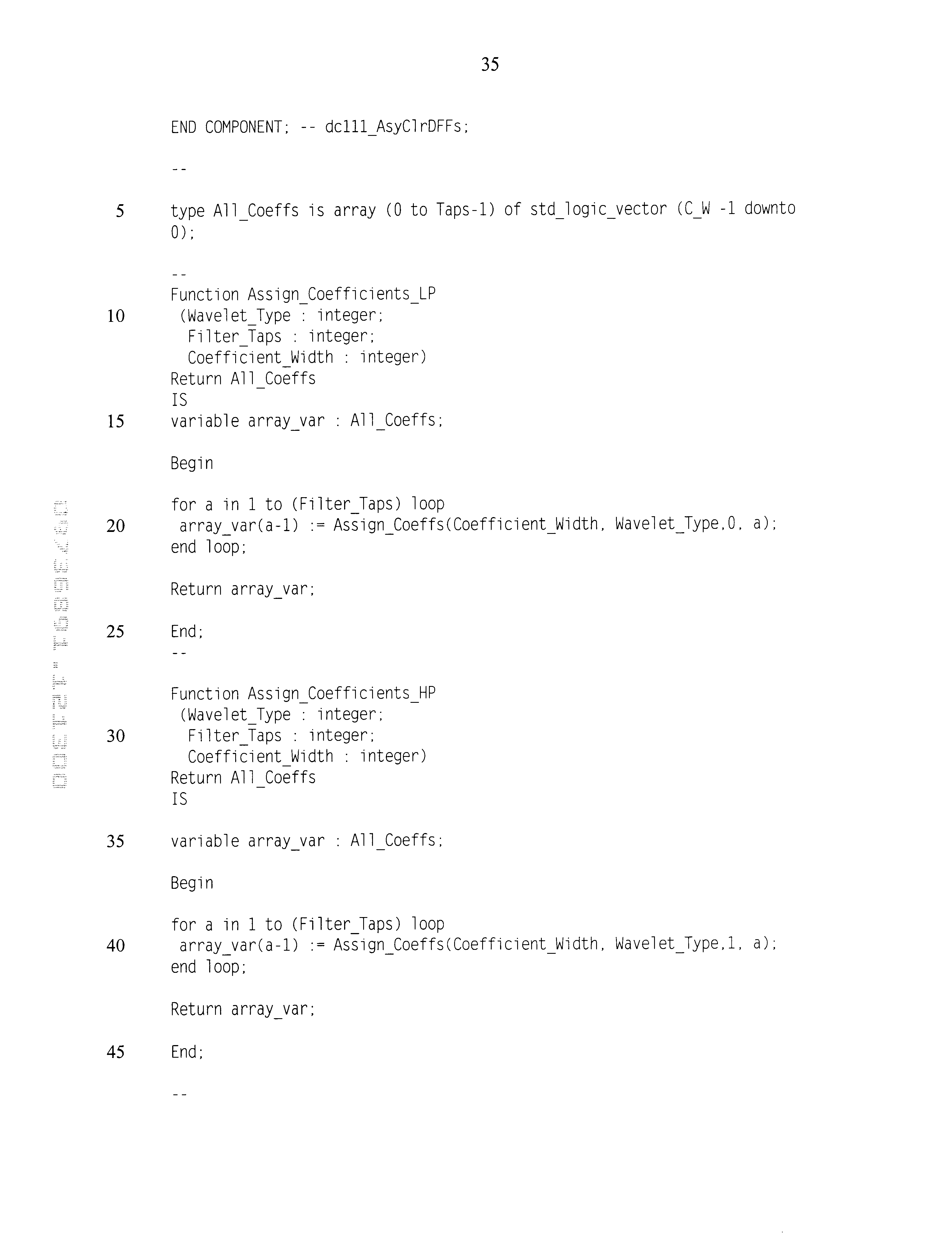
- the architecture starts by listing all the components that have been used in the design followed by functions, constants, signal and variables used in the design. Then there are two procedures which control the connection of delay line to the multipliers. The function defined earlier controls the connection of appropriate coefficients with the multiplier.
- the output circuit comprising adder and buffer memory and latch is then produced.
- Control_Block Reference 4
- All the algorithms (lines contained within functions and procedures and processes) are part of invention as they describe the method by which the scheme works.
Abstract
Description


| TABLE 1 | |||||
| Coefficient | Folding | Number of | |||
| Wavelet type | Data wordlength | wordlength | specified | Silicon area | gates |
| Daubechies 4-tap | 9 bits | 9 bits | 1 (No Folding) | 0.515 mm2 | 7.74 K |
| Daubechies 4-tap | 9 bits | 9 |
2 | 0.309 mm2 | 4.57 K |
| Daubechies 8-tap | 9 bits | 9 |
4 | 0.671 mm2 | 8.55 K |
| TABLE 2 |
| Specifications of three-level folded wavelet cores |
| Number of | Silicon | ||||||
| Level | Throughput | Wavelet type | Data wordlength | Coefficient wordlength | gates | area | |
| 1 | | Daubechies | 8 tap | 9 |
8 bits | 14.04 K | 1.21 mm2 |
| 2 | T/2 | |
13 |
8 bits | 11.61 K | 1.02 mm2 | |
| 3 | T/4 | |
17 |
8 bits | 9.82 K | 0.73 mm2 | |
| TABLE 3 |
| FPGA utilisation for a single stage folded architecture |
| Wavelet | Data | Coefficient | Number | Equivalent | Folding | Number of |
| function | wordlength | wordlength | of CLBs | gate count | level‡ | MACs* |
| |
9 bits† | 9 bits | 1018 | 13.9 K | 1 (no | 8 |
| tap, 1 level | folding) | |||||
| |
9 bits | 9 bits | 672 | 8.58 |
2 | 4 |
| | ||||||
| Daubechies | ||||||
| 8 | 9 bits | 9 |
412 | 5.35 |
4 | 2 |
| tap | ||||||
| †9 bits correspond to 8 bits magnitude + 1 sign bit. | ||||||
| ‡A folding of ‘1’ corresponds to the architecture shown in FIG. 3, folding of 2 corresponds to the architecture in FIG. 4 and so forth. | ||||||
| *The number of MACs is that required in producing a full filter bank stage, comprising one low-pass and one high-pass filter. | ||||||
| TABLE 4 |
| Entries of wavelet analysis and synthesis filter |
| Generic | |
| Wavelet type | |
| 1 | |
| 2 | |
| 3 | |
| 4 | Morlet, |
| 5 | |
| 6 | |
| . . . | . . . |
| (Synthesis filters) | |
| 1001 | |
| 1002 | |
| 1003 | |
| 1004 | |
| 1005 | Morlet, synthesis |
| 1006 | Symmlet, synthesis |
| . . . | . . . |
| e.g. to generate the delay line: | ||
| for i = 1 to number_of_taps loop | ||
| generate delay_line_elements | ||
| end loop | ||
| e.g. to generate MACs | ||
| for i=1 to (Taps/Decim) loop | ||
| generate multipliers_accumulators | ||
| end loop | ||


Claims (12)
Priority Applications (1)
| Application Number | Priority Date | Filing Date | Title |
|---|---|---|---|
| US09/736,891 US6785700B2 (en) | 2000-12-13 | 2000-12-13 | Implementation of wavelet functions in hardware |
Applications Claiming Priority (1)
| Application Number | Priority Date | Filing Date | Title |
|---|---|---|---|
| US09/736,891 US6785700B2 (en) | 2000-12-13 | 2000-12-13 | Implementation of wavelet functions in hardware |
Publications (2)
| Publication Number | Publication Date |
|---|---|
| US20020107899A1 US20020107899A1 (en) | 2002-08-08 |
| US6785700B2 true US6785700B2 (en) | 2004-08-31 |
Family
ID=24961751
Family Applications (1)
| Application Number | Title | Priority Date | Filing Date |
|---|---|---|---|
| US09/736,891 Expired - Lifetime US6785700B2 (en) | 2000-12-13 | 2000-12-13 | Implementation of wavelet functions in hardware |
Country Status (1)
| Country | Link |
|---|---|
| US (1) | US6785700B2 (en) |
Cited By (60)
| Publication number | Priority date | Publication date | Assignee | Title |
|---|---|---|---|---|
| US20030065489A1 (en) * | 2001-06-01 | 2003-04-03 | David Guevorkian | Architectures for discrete wavelet transforms |
| US20040062446A1 (en) * | 2002-09-26 | 2004-04-01 | Nec Electronics Corporation | Image processing apparatus supporting both discrete cosine transform and discrete wavelet transform |
| US20040223655A1 (en) * | 2003-05-09 | 2004-11-11 | Telecommunications Research Laboratories | Implementation of discrete wavelet transform using lifting steps |
| US20060117371A1 (en) * | 2001-03-15 | 2006-06-01 | Digital Display Innovations, Llc | Method for effectively implementing a multi-room television system |
| US20060282855A1 (en) * | 2005-05-05 | 2006-12-14 | Digital Display Innovations, Llc | Multiple remote display system |
| US20070097130A1 (en) * | 2005-11-01 | 2007-05-03 | Digital Display Innovations, Llc | Multi-user terminal services accelerator |
| US20070124474A1 (en) * | 2005-11-30 | 2007-05-31 | Digital Display Innovations, Llc | Multi-user display proxy server |
| US20070156801A1 (en) * | 2001-06-01 | 2007-07-05 | David Guevorkian | Flowgraph representation of discrete wavelet transforms and wavelet packets for their efficient parallel implementation |
| US20070284002A1 (en) * | 2006-06-09 | 2007-12-13 | Hartman Brian T | Fixed cone sleeve valve having cone supported by means downstream of the gate in its closed position |
| US20070297500A1 (en) * | 2006-06-22 | 2007-12-27 | Jiun-In Guo | Design techniques and their circuit designs for versatile and scalable video coding |
| US20080049841A1 (en) * | 2006-08-24 | 2008-02-28 | Eric Jeffrey | Hardware Method for Performing Real Time Multi-Level Wavelet Decomposition |
| US20080059533A1 (en) * | 2005-06-07 | 2008-03-06 | Sling Media, Inc. | Personal video recorder functionality for placeshifting systems |
| US20080112489A1 (en) * | 2006-11-09 | 2008-05-15 | Calista Technologies | System and method for effectively encoding and decoding electronic information |
| US7415692B1 (en) * | 2002-11-13 | 2008-08-19 | Altera Corporation | Method for programming programmable logic device with blocks that perform multiplication and other arithmetic functions |
| US20090080448A1 (en) * | 2007-09-26 | 2009-03-26 | Sling Media Inc. | Media streaming device with gateway functionality |
| US7647614B2 (en) | 2004-06-07 | 2010-01-12 | Sling Media, Inc. | Fast-start streaming and buffering of streaming content for personal media player |
| US7667707B1 (en) | 2005-05-05 | 2010-02-23 | Digital Display Innovations, Llc | Computer system for supporting multiple remote displays |
| US20100064055A1 (en) * | 2008-09-08 | 2010-03-11 | Sling Media Inc. | Systems and methods for projecting images from a computer system |
| US20100070925A1 (en) * | 2008-09-08 | 2010-03-18 | Sling Media Inc. | Systems and methods for selecting media content obtained from multple sources |
| US7702952B2 (en) | 2005-06-30 | 2010-04-20 | Sling Media, Inc. | Firmware update for consumer electronic device |
| US7720300B1 (en) | 2006-12-05 | 2010-05-18 | Calister Technologies | System and method for effectively performing an adaptive quantization procedure |
| US7725912B2 (en) | 1999-05-26 | 2010-05-25 | Sling Media, Inc. | Method for implementing a remote display system with transcoding |
| US7769756B2 (en) | 2004-06-07 | 2010-08-03 | Sling Media, Inc. | Selection and presentation of context-relevant supplemental content and advertising |
| US20100220821A1 (en) * | 2006-11-06 | 2010-09-02 | Qualcomm Incorporated | Narrow-band interference canceller |
| US20100228810A1 (en) * | 2009-03-03 | 2010-09-09 | Kuoruey Han | Method and system for unconstrained frequency domain adaptive filtering |
| US20100268832A1 (en) * | 2009-04-17 | 2010-10-21 | Sling Media Inc. | Systems and methods for establishing connections between devices communicating over a network |
| US20110035466A1 (en) * | 2009-08-10 | 2011-02-10 | Sling Media Pvt Ltd | Home media aggregator system and method |
| US20110035462A1 (en) * | 2009-08-06 | 2011-02-10 | Sling Media Pvt Ltd | Systems and methods for event programming via a remote media player |
| US20110035668A1 (en) * | 2009-08-10 | 2011-02-10 | Sling Media Pvt Ltd | Systems and methods for virtual remote control of streamed media |
| US20110035765A1 (en) * | 2009-08-10 | 2011-02-10 | Sling Media Pvt Ltd | Systems and methods for providing programming content |
| US20110032986A1 (en) * | 2009-08-07 | 2011-02-10 | Sling Media Pvt Ltd | Systems and methods for automatically controlling the resolution of streaming video content |
| US20110033168A1 (en) * | 2009-08-10 | 2011-02-10 | Sling Media Pvt Ltd | Methods and apparatus for fast seeking within a media stream buffer |
| US20110055864A1 (en) * | 2009-08-26 | 2011-03-03 | Sling Media Inc. | Systems and methods for transcoding and place shifting media content |
| US20110113354A1 (en) * | 2009-11-12 | 2011-05-12 | Sling Media Pvt Ltd | Always-on-top media player launched from a web browser |
| US20110119325A1 (en) * | 2009-11-16 | 2011-05-19 | Sling Media Inc. | Systems and methods for delivering messages over a network |
| US20110150432A1 (en) * | 2009-12-23 | 2011-06-23 | Sling Media Inc. | Systems and methods for remotely controlling a media server via a network |
| US20110153845A1 (en) * | 2009-12-18 | 2011-06-23 | Sling Media Inc. | Methods and apparatus for establishing network connections using an inter-mediating device |
| US7975062B2 (en) | 2004-06-07 | 2011-07-05 | Sling Media, Inc. | Capturing and sharing media content |
| US8019883B1 (en) | 2005-05-05 | 2011-09-13 | Digital Display Innovations, Llc | WiFi peripheral mode display system |
| US8060609B2 (en) | 2008-01-04 | 2011-11-15 | Sling Media Inc. | Systems and methods for determining attributes of media items accessed via a personal media broadcaster |
| US8099755B2 (en) | 2004-06-07 | 2012-01-17 | Sling Media Pvt. Ltd. | Systems and methods for controlling the encoding of a media stream |
| US8200796B1 (en) | 2005-05-05 | 2012-06-12 | Digital Display Innovations, Llc | Graphics display system for multiple remote terminals |
| US8314893B2 (en) | 2009-08-28 | 2012-11-20 | Sling Media Pvt. Ltd. | Remote control and method for automatically adjusting the volume output of an audio device |
| US8346605B2 (en) | 2004-06-07 | 2013-01-01 | Sling Media, Inc. | Management of shared media content |
| US8350971B2 (en) | 2007-10-23 | 2013-01-08 | Sling Media, Inc. | Systems and methods for controlling media devices |
| US8381310B2 (en) | 2009-08-13 | 2013-02-19 | Sling Media Pvt. Ltd. | Systems, methods, and program applications for selectively restricting the placeshifting of copy protected digital media content |
| US8406431B2 (en) | 2009-07-23 | 2013-03-26 | Sling Media Pvt. Ltd. | Adaptive gain control for digital audio samples in a media stream |
| US8438602B2 (en) | 2009-01-26 | 2013-05-07 | Sling Media Inc. | Systems and methods for linking media content |
| US8626879B2 (en) | 2009-12-22 | 2014-01-07 | Sling Media, Inc. | Systems and methods for establishing network connections using local mediation services |
| US8667279B2 (en) | 2008-07-01 | 2014-03-04 | Sling Media, Inc. | Systems and methods for securely place shifting media content |
| US8799408B2 (en) | 2009-08-10 | 2014-08-05 | Sling Media Pvt Ltd | Localization systems and methods |
| US8856349B2 (en) | 2010-02-05 | 2014-10-07 | Sling Media Inc. | Connection priority services for data communication between two devices |
| US8966101B2 (en) | 2009-08-10 | 2015-02-24 | Sling Media Pvt Ltd | Systems and methods for updating firmware over a network |
| US9191610B2 (en) | 2008-11-26 | 2015-11-17 | Sling Media Pvt Ltd. | Systems and methods for creating logical media streams for media storage and playback |
| US9275054B2 (en) | 2009-12-28 | 2016-03-01 | Sling Media, Inc. | Systems and methods for searching media content |
| US9565479B2 (en) | 2009-08-10 | 2017-02-07 | Sling Media Pvt Ltd. | Methods and apparatus for seeking within a media stream using scene detection |
| US9998802B2 (en) | 2004-06-07 | 2018-06-12 | Sling Media LLC | Systems and methods for creating variable length clips from a media stream |
| US11190166B2 (en) | 2005-02-23 | 2021-11-30 | Murata Vios, Inc. | Signal segmentation and analysis |
| US11602311B2 (en) | 2019-01-29 | 2023-03-14 | Murata Vios, Inc. | Pulse oximetry system |
| US11675560B2 (en) | 2005-05-05 | 2023-06-13 | Iii Holdings 1, Llc | Methods and apparatus for mesh networking using wireless devices |
Families Citing this family (3)
| Publication number | Priority date | Publication date | Assignee | Title |
|---|---|---|---|---|
| US20030055856A1 (en) * | 2001-09-19 | 2003-03-20 | Mccanny Paul Gerard | Architecture component and method for performing discrete wavelet transforms |
| US7412103B2 (en) * | 2003-10-20 | 2008-08-12 | Lawrence Livermore National Security, Llc | 3D wavelet-based filter and method |
| CN107888164A (en) * | 2017-12-15 | 2018-04-06 | 首都师范大学 | A kind of wavelet decomposition transform system and implementation method based on FPGA |
Citations (5)
| Publication number | Priority date | Publication date | Assignee | Title |
|---|---|---|---|---|
| US5453945A (en) * | 1994-01-13 | 1995-09-26 | Tucker; Michael R. | Method for decomposing signals into efficient time-frequency representations for data compression and recognition |
| US5706220A (en) * | 1996-05-14 | 1998-01-06 | Lsi Logic Corporation | System and method for implementing the fast wavelet transform |
| US5875122A (en) * | 1996-12-17 | 1999-02-23 | Intel Corporation | Integrated systolic architecture for decomposition and reconstruction of signals using wavelet transforms |
| US6182102B1 (en) * | 1996-05-14 | 2001-01-30 | Lsi Logic Corporation | System and method for implementation of inverse wavelet transforms |
| US6278753B1 (en) * | 1999-05-03 | 2001-08-21 | Motorola, Inc. | Method and apparatus of creating and implementing wavelet filters in a digital system |
-
2000
- 2000-12-13 US US09/736,891 patent/US6785700B2/en not_active Expired - Lifetime
Patent Citations (5)
| Publication number | Priority date | Publication date | Assignee | Title |
|---|---|---|---|---|
| US5453945A (en) * | 1994-01-13 | 1995-09-26 | Tucker; Michael R. | Method for decomposing signals into efficient time-frequency representations for data compression and recognition |
| US5706220A (en) * | 1996-05-14 | 1998-01-06 | Lsi Logic Corporation | System and method for implementing the fast wavelet transform |
| US6182102B1 (en) * | 1996-05-14 | 2001-01-30 | Lsi Logic Corporation | System and method for implementation of inverse wavelet transforms |
| US5875122A (en) * | 1996-12-17 | 1999-02-23 | Intel Corporation | Integrated systolic architecture for decomposition and reconstruction of signals using wavelet transforms |
| US6278753B1 (en) * | 1999-05-03 | 2001-08-21 | Motorola, Inc. | Method and apparatus of creating and implementing wavelet filters in a digital system |
Cited By (121)
| Publication number | Priority date | Publication date | Assignee | Title |
|---|---|---|---|---|
| US9584757B2 (en) | 1999-05-26 | 2017-02-28 | Sling Media, Inc. | Apparatus and method for effectively implementing a wireless television system |
| US7992176B2 (en) | 1999-05-26 | 2011-08-02 | Sling Media, Inc. | Apparatus and method for effectively implementing a wireless television system |
| US7725912B2 (en) | 1999-05-26 | 2010-05-25 | Sling Media, Inc. | Method for implementing a remote display system with transcoding |
| US9781473B2 (en) | 1999-05-26 | 2017-10-03 | Echostar Technologies L.L.C. | Method for effectively implementing a multi-room television system |
| US9491523B2 (en) | 1999-05-26 | 2016-11-08 | Echostar Technologies L.L.C. | Method for effectively implementing a multi-room television system |
| US20060117371A1 (en) * | 2001-03-15 | 2006-06-01 | Digital Display Innovations, Llc | Method for effectively implementing a multi-room television system |
| US8266657B2 (en) | 2001-03-15 | 2012-09-11 | Sling Media Inc. | Method for effectively implementing a multi-room television system |
| US20070156801A1 (en) * | 2001-06-01 | 2007-07-05 | David Guevorkian | Flowgraph representation of discrete wavelet transforms and wavelet packets for their efficient parallel implementation |
| US6976046B2 (en) * | 2001-06-01 | 2005-12-13 | Nokia Corporation | Architectures for discrete wavelet transforms |
| US20030065489A1 (en) * | 2001-06-01 | 2003-04-03 | David Guevorkian | Architectures for discrete wavelet transforms |
| US20040062446A1 (en) * | 2002-09-26 | 2004-04-01 | Nec Electronics Corporation | Image processing apparatus supporting both discrete cosine transform and discrete wavelet transform |
| US7346640B2 (en) * | 2002-09-26 | 2008-03-18 | Nec Electronics Corporation | Image processing apparatus supporting both discrete cosine transform and discrete wavelet transform |
| US7415692B1 (en) * | 2002-11-13 | 2008-08-19 | Altera Corporation | Method for programming programmable logic device with blocks that perform multiplication and other arithmetic functions |
| US20040223655A1 (en) * | 2003-05-09 | 2004-11-11 | Telecommunications Research Laboratories | Implementation of discrete wavelet transform using lifting steps |
| US7480416B2 (en) * | 2003-05-09 | 2009-01-20 | Telecommunications Research Laboratories | Implementation of discrete wavelet transform using lifting steps |
| US8904455B2 (en) | 2004-06-07 | 2014-12-02 | Sling Media Inc. | Personal video recorder functionality for placeshifting systems |
| US9716910B2 (en) | 2004-06-07 | 2017-07-25 | Sling Media, L.L.C. | Personal video recorder functionality for placeshifting systems |
| US7975062B2 (en) | 2004-06-07 | 2011-07-05 | Sling Media, Inc. | Capturing and sharing media content |
| US8799969B2 (en) | 2004-06-07 | 2014-08-05 | Sling Media, Inc. | Capturing and sharing media content |
| US7647614B2 (en) | 2004-06-07 | 2010-01-12 | Sling Media, Inc. | Fast-start streaming and buffering of streaming content for personal media player |
| US8819750B2 (en) | 2004-06-07 | 2014-08-26 | Sling Media, Inc. | Personal media broadcasting system with output buffer |
| US8346605B2 (en) | 2004-06-07 | 2013-01-01 | Sling Media, Inc. | Management of shared media content |
| US9106723B2 (en) | 2004-06-07 | 2015-08-11 | Sling Media, Inc. | Fast-start streaming and buffering of streaming content for personal media player |
| US7921446B2 (en) | 2004-06-07 | 2011-04-05 | Sling Media, Inc. | Fast-start streaming and buffering of streaming content for personal media player |
| US7707614B2 (en) | 2004-06-07 | 2010-04-27 | Sling Media, Inc. | Personal media broadcasting system with output buffer |
| US10123067B2 (en) | 2004-06-07 | 2018-11-06 | Sling Media L.L.C. | Personal video recorder functionality for placeshifting systems |
| US8621533B2 (en) | 2004-06-07 | 2013-12-31 | Sling Media, Inc. | Fast-start streaming and buffering of streaming content for personal media player |
| US9253241B2 (en) | 2004-06-07 | 2016-02-02 | Sling Media Inc. | Personal media broadcasting system with output buffer |
| US9356984B2 (en) | 2004-06-07 | 2016-05-31 | Sling Media, Inc. | Capturing and sharing media content |
| US7769756B2 (en) | 2004-06-07 | 2010-08-03 | Sling Media, Inc. | Selection and presentation of context-relevant supplemental content and advertising |
| US8060909B2 (en) | 2004-06-07 | 2011-11-15 | Sling Media, Inc. | Personal media broadcasting system |
| US9998802B2 (en) | 2004-06-07 | 2018-06-12 | Sling Media LLC | Systems and methods for creating variable length clips from a media stream |
| US8365236B2 (en) | 2004-06-07 | 2013-01-29 | Sling Media, Inc. | Personal media broadcasting system with output buffer |
| US7877776B2 (en) | 2004-06-07 | 2011-01-25 | Sling Media, Inc. | Personal media broadcasting system |
| US8051454B2 (en) | 2004-06-07 | 2011-11-01 | Sling Media, Inc. | Personal media broadcasting system with output buffer |
| US8099755B2 (en) | 2004-06-07 | 2012-01-17 | Sling Media Pvt. Ltd. | Systems and methods for controlling the encoding of a media stream |
| US11190166B2 (en) | 2005-02-23 | 2021-11-30 | Murata Vios, Inc. | Signal segmentation and analysis |
| US11733958B2 (en) | 2005-05-05 | 2023-08-22 | Iii Holdings 1, Llc | Wireless mesh-enabled system, host device, and method for use therewith |
| US7667707B1 (en) | 2005-05-05 | 2010-02-23 | Digital Display Innovations, Llc | Computer system for supporting multiple remote displays |
| US20060282855A1 (en) * | 2005-05-05 | 2006-12-14 | Digital Display Innovations, Llc | Multiple remote display system |
| US8019883B1 (en) | 2005-05-05 | 2011-09-13 | Digital Display Innovations, Llc | WiFi peripheral mode display system |
| US10877716B2 (en) | 2005-05-05 | 2020-12-29 | Iii Holdings 1, Llc | WiFi remote displays |
| US11675560B2 (en) | 2005-05-05 | 2023-06-13 | Iii Holdings 1, Llc | Methods and apparatus for mesh networking using wireless devices |
| US9344237B2 (en) | 2005-05-05 | 2016-05-17 | Iii Holdings 1, Llc | WiFi remote displays |
| US11132164B2 (en) | 2005-05-05 | 2021-09-28 | Iii Holdings 1, Llc | WiFi remote displays |
| US8200796B1 (en) | 2005-05-05 | 2012-06-12 | Digital Display Innovations, Llc | Graphics display system for multiple remote terminals |
| US9237300B2 (en) | 2005-06-07 | 2016-01-12 | Sling Media Inc. | Personal video recorder functionality for placeshifting systems |
| US7917932B2 (en) | 2005-06-07 | 2011-03-29 | Sling Media, Inc. | Personal video recorder functionality for placeshifting systems |
| US20080059533A1 (en) * | 2005-06-07 | 2008-03-06 | Sling Media, Inc. | Personal video recorder functionality for placeshifting systems |
| US20100192007A1 (en) * | 2005-06-30 | 2010-07-29 | Sling Media Inc. | Firmware update for consumer electronic device |
| US7702952B2 (en) | 2005-06-30 | 2010-04-20 | Sling Media, Inc. | Firmware update for consumer electronic device |
| US8041988B2 (en) | 2005-06-30 | 2011-10-18 | Sling Media Inc. | Firmware update for consumer electronic device |
| US20070097130A1 (en) * | 2005-11-01 | 2007-05-03 | Digital Display Innovations, Llc | Multi-user terminal services accelerator |
| US7899864B2 (en) | 2005-11-01 | 2011-03-01 | Microsoft Corporation | Multi-user terminal services accelerator |
| US20070124474A1 (en) * | 2005-11-30 | 2007-05-31 | Digital Display Innovations, Llc | Multi-user display proxy server |
| US8112513B2 (en) | 2005-11-30 | 2012-02-07 | Microsoft Corporation | Multi-user display proxy server |
| US20070284002A1 (en) * | 2006-06-09 | 2007-12-13 | Hartman Brian T | Fixed cone sleeve valve having cone supported by means downstream of the gate in its closed position |
| US20070297500A1 (en) * | 2006-06-22 | 2007-12-27 | Jiun-In Guo | Design techniques and their circuit designs for versatile and scalable video coding |
| US7724975B2 (en) * | 2006-06-22 | 2010-05-25 | National Chun Cheng University | Design techniques and their circuit designs for versatile and scalable video coding |
| US20080049841A1 (en) * | 2006-08-24 | 2008-02-28 | Eric Jeffrey | Hardware Method for Performing Real Time Multi-Level Wavelet Decomposition |
| US20100220821A1 (en) * | 2006-11-06 | 2010-09-02 | Qualcomm Incorporated | Narrow-band interference canceller |
| US8433016B2 (en) * | 2006-11-06 | 2013-04-30 | Qualcomm Incorporated | Narrow-band interference canceller |
| US20080112489A1 (en) * | 2006-11-09 | 2008-05-15 | Calista Technologies | System and method for effectively encoding and decoding electronic information |
| US7460725B2 (en) | 2006-11-09 | 2008-12-02 | Calista Technologies, Inc. | System and method for effectively encoding and decoding electronic information |
| US7720300B1 (en) | 2006-12-05 | 2010-05-18 | Calister Technologies | System and method for effectively performing an adaptive quantization procedure |
| US8477793B2 (en) | 2007-09-26 | 2013-07-02 | Sling Media, Inc. | Media streaming device with gateway functionality |
| US20090080448A1 (en) * | 2007-09-26 | 2009-03-26 | Sling Media Inc. | Media streaming device with gateway functionality |
| US8958019B2 (en) | 2007-10-23 | 2015-02-17 | Sling Media, Inc. | Systems and methods for controlling media devices |
| US8350971B2 (en) | 2007-10-23 | 2013-01-08 | Sling Media, Inc. | Systems and methods for controlling media devices |
| US8060609B2 (en) | 2008-01-04 | 2011-11-15 | Sling Media Inc. | Systems and methods for determining attributes of media items accessed via a personal media broadcaster |
| US9143827B2 (en) | 2008-07-01 | 2015-09-22 | Sling Media, Inc. | Systems and methods for securely place shifting media content |
| US9510035B2 (en) | 2008-07-01 | 2016-11-29 | Sling Media, Inc. | Systems and methods for securely streaming media content |
| US8667279B2 (en) | 2008-07-01 | 2014-03-04 | Sling Media, Inc. | Systems and methods for securely place shifting media content |
| US9942587B2 (en) | 2008-07-01 | 2018-04-10 | Sling Media L.L.C. | Systems and methods for securely streaming media content |
| US8966658B2 (en) | 2008-08-13 | 2015-02-24 | Sling Media Pvt Ltd | Systems, methods, and program applications for selectively restricting the placeshifting of copy protected digital media content |
| US9600222B2 (en) | 2008-09-08 | 2017-03-21 | Sling Media Inc. | Systems and methods for projecting images from a computer system |
| US8667163B2 (en) | 2008-09-08 | 2014-03-04 | Sling Media Inc. | Systems and methods for projecting images from a computer system |
| US20100070925A1 (en) * | 2008-09-08 | 2010-03-18 | Sling Media Inc. | Systems and methods for selecting media content obtained from multple sources |
| US20100064055A1 (en) * | 2008-09-08 | 2010-03-11 | Sling Media Inc. | Systems and methods for projecting images from a computer system |
| US9191610B2 (en) | 2008-11-26 | 2015-11-17 | Sling Media Pvt Ltd. | Systems and methods for creating logical media streams for media storage and playback |
| US8438602B2 (en) | 2009-01-26 | 2013-05-07 | Sling Media Inc. | Systems and methods for linking media content |
| US20140079101A1 (en) * | 2009-03-03 | 2014-03-20 | Broadcom Corporation | Method and system for unconstrained frequency domain adaptive filtering |
| US20100228810A1 (en) * | 2009-03-03 | 2010-09-09 | Kuoruey Han | Method and system for unconstrained frequency domain adaptive filtering |
| US8984038B2 (en) * | 2009-03-03 | 2015-03-17 | Broadcom Corporation | Method and system for unconstrained frequency domain adaptive filtering |
| US8595278B2 (en) * | 2009-03-03 | 2013-11-26 | Broadcom Corporation | Method and system for unconstrained frequency domain adaptive filtering |
| US20100268832A1 (en) * | 2009-04-17 | 2010-10-21 | Sling Media Inc. | Systems and methods for establishing connections between devices communicating over a network |
| US8171148B2 (en) | 2009-04-17 | 2012-05-01 | Sling Media, Inc. | Systems and methods for establishing connections between devices communicating over a network |
| US9225785B2 (en) | 2009-04-17 | 2015-12-29 | Sling Media, Inc. | Systems and methods for establishing connections between devices communicating over a network |
| US8406431B2 (en) | 2009-07-23 | 2013-03-26 | Sling Media Pvt. Ltd. | Adaptive gain control for digital audio samples in a media stream |
| US9491538B2 (en) | 2009-07-23 | 2016-11-08 | Sling Media Pvt Ltd. | Adaptive gain control for digital audio samples in a media stream |
| US20110035462A1 (en) * | 2009-08-06 | 2011-02-10 | Sling Media Pvt Ltd | Systems and methods for event programming via a remote media player |
| US9479737B2 (en) | 2009-08-06 | 2016-10-25 | Echostar Technologies L.L.C. | Systems and methods for event programming via a remote media player |
| US20110032986A1 (en) * | 2009-08-07 | 2011-02-10 | Sling Media Pvt Ltd | Systems and methods for automatically controlling the resolution of streaming video content |
| US9525838B2 (en) | 2009-08-10 | 2016-12-20 | Sling Media Pvt. Ltd. | Systems and methods for virtual remote control of streamed media |
| US20110035466A1 (en) * | 2009-08-10 | 2011-02-10 | Sling Media Pvt Ltd | Home media aggregator system and method |
| US8966101B2 (en) | 2009-08-10 | 2015-02-24 | Sling Media Pvt Ltd | Systems and methods for updating firmware over a network |
| US8532472B2 (en) | 2009-08-10 | 2013-09-10 | Sling Media Pvt Ltd | Methods and apparatus for fast seeking within a media stream buffer |
| US20110035765A1 (en) * | 2009-08-10 | 2011-02-10 | Sling Media Pvt Ltd | Systems and methods for providing programming content |
| US10620827B2 (en) | 2009-08-10 | 2020-04-14 | Sling Media Pvt Ltd | Systems and methods for virtual remote control of streamed media |
| US8799408B2 (en) | 2009-08-10 | 2014-08-05 | Sling Media Pvt Ltd | Localization systems and methods |
| US20110035668A1 (en) * | 2009-08-10 | 2011-02-10 | Sling Media Pvt Ltd | Systems and methods for virtual remote control of streamed media |
| US20110033168A1 (en) * | 2009-08-10 | 2011-02-10 | Sling Media Pvt Ltd | Methods and apparatus for fast seeking within a media stream buffer |
| US9565479B2 (en) | 2009-08-10 | 2017-02-07 | Sling Media Pvt Ltd. | Methods and apparatus for seeking within a media stream using scene detection |
| US8381310B2 (en) | 2009-08-13 | 2013-02-19 | Sling Media Pvt. Ltd. | Systems, methods, and program applications for selectively restricting the placeshifting of copy protected digital media content |
| US9160974B2 (en) | 2009-08-26 | 2015-10-13 | Sling Media, Inc. | Systems and methods for transcoding and place shifting media content |
| US20110055864A1 (en) * | 2009-08-26 | 2011-03-03 | Sling Media Inc. | Systems and methods for transcoding and place shifting media content |
| US10230923B2 (en) | 2009-08-26 | 2019-03-12 | Sling Media LLC | Systems and methods for transcoding and place shifting media content |
| US8314893B2 (en) | 2009-08-28 | 2012-11-20 | Sling Media Pvt. Ltd. | Remote control and method for automatically adjusting the volume output of an audio device |
| US20110113354A1 (en) * | 2009-11-12 | 2011-05-12 | Sling Media Pvt Ltd | Always-on-top media player launched from a web browser |
| US20110119325A1 (en) * | 2009-11-16 | 2011-05-19 | Sling Media Inc. | Systems and methods for delivering messages over a network |
| US10021073B2 (en) | 2009-11-16 | 2018-07-10 | Sling Media L.L.C. | Systems and methods for delivering messages over a network |
| US9015225B2 (en) | 2009-11-16 | 2015-04-21 | Echostar Technologies L.L.C. | Systems and methods for delivering messages over a network |
| US20110153845A1 (en) * | 2009-12-18 | 2011-06-23 | Sling Media Inc. | Methods and apparatus for establishing network connections using an inter-mediating device |
| US8799485B2 (en) | 2009-12-18 | 2014-08-05 | Sling Media, Inc. | Methods and apparatus for establishing network connections using an inter-mediating device |
| US8626879B2 (en) | 2009-12-22 | 2014-01-07 | Sling Media, Inc. | Systems and methods for establishing network connections using local mediation services |
| US9178923B2 (en) | 2009-12-23 | 2015-11-03 | Echostar Technologies L.L.C. | Systems and methods for remotely controlling a media server via a network |
| US20110150432A1 (en) * | 2009-12-23 | 2011-06-23 | Sling Media Inc. | Systems and methods for remotely controlling a media server via a network |
| US10097899B2 (en) | 2009-12-28 | 2018-10-09 | Sling Media L.L.C. | Systems and methods for searching media content |
| US9275054B2 (en) | 2009-12-28 | 2016-03-01 | Sling Media, Inc. | Systems and methods for searching media content |
| US8856349B2 (en) | 2010-02-05 | 2014-10-07 | Sling Media Inc. | Connection priority services for data communication between two devices |
| US11602311B2 (en) | 2019-01-29 | 2023-03-14 | Murata Vios, Inc. | Pulse oximetry system |
Also Published As
| Publication number | Publication date |
|---|---|
| US20020107899A1 (en) | 2002-08-08 |
Similar Documents
| Publication | Publication Date | Title |
|---|---|---|
| US6785700B2 (en) | Implementation of wavelet functions in hardware | |
| Chakrabarti et al. | Efficient realizations of the discrete and continuous wavelet transforms: From single chip implementations to mappings on SIMD array computers | |
| Liao et al. | Efficient architectures for 1-D and 2-D lifting-based wavelet transforms | |
| Grzeszczak et al. | VLSI implementation of discrete wavelet transform | |
| Mahmoud et al. | Comparison between haar and daubechies wavelet transformions on FPGA technology | |
| EP1412911B1 (en) | Architectures for discrete wavelet transforms | |
| Sripathi | Efficient implementations of discrete wavelet transforms using FPGAs | |
| Marino | Two fast architectures for the direct 2-D discrete wavelet transform | |
| Wang et al. | Efficient VLSI architecture for lifting-based discrete wavelet packet transform | |
| Masud et al. | Reusable silicon IP cores for discrete wavelet transform applications | |
| Chakraborty et al. | A memory and area-efficient distributed arithmetic based modular VLSI architecture of 1D/2D reconfigurable 9/7 and 5/3 DWT filters for real-time image decomposition | |
| Uzun et al. | Framework for FPGA-based discrete biorthogonal wavelet transforms implementation | |
| Trenas et al. | A configurable architecture for the wavelet packet transform | |
| Masud et al. | Rapid design of biorthogonal wavelet transforms | |
| Zheng et al. | Optimized FPGA implementation of multi-rate FIR filters through thread decomposition | |
| Limqueco et al. | A scalable architecture for 2-D discrete wavelet transform | |
| Sundararajan et al. | Synthesis of folded, pipelined architectures for multi-dimensional multirate systems | |
| Chakraborty et al. | A memory Efficient, multiplierless & modular VLSI architecture of 1D/2D Re-Configurable 9/7 & 5/3 DWT filters using Distributed Arithmetic | |
| Yin et al. | A novel flexible foldable systolic architecture FIR filters generator | |
| Rullmann | A new VLSI architecture for the discrete wavelet transform using the lifting scheme | |
| Panneerselvam et al. | Implementation of fast Fourier transforms and discrete cosine transforms in FPGAs | |
| Aroutchelvame et al. | Architecture of wavelet packet transform for 1-D signal | |
| Cox et al. | Discrete wavelet transform signal analyzer | |
| Shiau et al. | Efficient architectures for the biorthogonal wavelet transform by filter bank and lifting scheme | |
| Masud et al. | Wavelet packet transforms for system-on-chip applications |
Legal Events
| Date | Code | Title | Description |
|---|---|---|---|
| AS | Assignment |
Owner name: AMPHION SEMICONDUCTOR LIMITED, A NORTHERN IRELAND Free format text: ASSIGNMENT OF ASSIGNORS INTEREST;ASSIGNOR:INTEGRAGED SILICON SYSTEMS LIMITED;REEL/FRAME:011921/0813 Effective date: 20010122 |
|
| AS | Assignment |
Owner name: AMPHION SEMICONDUCTOR LIMITED, UNITED KINGDOM Free format text: CHANGE OF NAME;ASSIGNOR:INTEGRATED SILICON SYSTEMS LIMITED;REEL/FRAME:012584/0759 Effective date: 20010122 |
|
| AS | Assignment |
Owner name: AMPHION SEMICONDCUTOR LIMITED (NORTHERN IRELAND CO Free format text: CORRECTIVE ASSIGNMENT TO CORRECT THE NAME OF THE ASSIGNOR, PREVIOUSLY RECORDED ON REEL 011921 FRAME 0813;ASSIGNOR:INTEGRATED SILICON SYSTEMS LIMITED;REEL/FRAME:013106/0248 Effective date: 20010122 |
|
| STCF | Information on status: patent grant |
Free format text: PATENTED CASE |
|
| AS | Assignment |
Owner name: CONEXANT SYSTEMS, INC., CALIFORNIA Free format text: ASSIGNMENT OF ASSIGNORS INTEREST;ASSIGNOR:AMPHION SEMICONDUCTOR LIMITED;REEL/FRAME:017411/0919 Effective date: 20060109 |
|
| AS | Assignment |
Owner name: BANK OF NEW YORK TRUST COMPANY, N.A.,ILLINOIS Free format text: SECURITY AGREEMENT;ASSIGNOR:CONEXANT SYSTEMS, INC.;REEL/FRAME:018711/0818 Effective date: 20061113 Owner name: BANK OF NEW YORK TRUST COMPANY, N.A., ILLINOIS Free format text: SECURITY AGREEMENT;ASSIGNOR:CONEXANT SYSTEMS, INC.;REEL/FRAME:018711/0818 Effective date: 20061113 |
|
| FEPP | Fee payment procedure |
Free format text: PAT HOLDER NO LONGER CLAIMS SMALL ENTITY STATUS, ENTITY STATUS SET TO UNDISCOUNTED (ORIGINAL EVENT CODE: STOL); ENTITY STATUS OF PATENT OWNER: LARGE ENTITY |
|
| FPAY | Fee payment |
Year of fee payment: 4 |
|
| AS | Assignment |
Owner name: INTEGRATED SILICON SYSTEMS LIMITED, IRELAND Free format text: ASSIGNMENT OF ASSIGNORS INTEREST;ASSIGNORS:MASUD, SHAHID;MCCANNY, JOHN VINCENT;REEL/FRAME:020593/0849 Effective date: 20010205 |
|
| REMI | Maintenance fee reminder mailed | ||
| AS | Assignment |
Owner name: CONEXANT SYSTEMS, INC., CALIFORNIA Free format text: RELEASE BY SECURED PARTY;ASSIGNOR:BANK OF NEW YORK MELLON TRUST COMPANY, N.A. (FORMERLY, BANK OF NEW YORK TRUST COMPANY, N.A.);REEL/FRAME:021523/0804 Effective date: 20080808 Owner name: CONEXANT SYSTEMS, INC.,CALIFORNIA Free format text: RELEASE BY SECURED PARTY;ASSIGNOR:BANK OF NEW YORK MELLON TRUST COMPANY, N.A. (FORMERLY, BANK OF NEW YORK TRUST COMPANY, N.A.);REEL/FRAME:021523/0804 Effective date: 20080808 |
|
| AS | Assignment |
Owner name: NXP, B.V., NETHERLANDS Free format text: ASSIGNMENT OF ASSIGNORS INTEREST;ASSIGNOR:CONEXANT SYSTEMS, INC.;REEL/FRAME:021531/0523 Effective date: 20080808 Owner name: NXP, B.V.,NETHERLANDS Free format text: ASSIGNMENT OF ASSIGNORS INTEREST;ASSIGNOR:CONEXANT SYSTEMS, INC.;REEL/FRAME:021531/0523 Effective date: 20080808 |
|
| AS | Assignment |
Owner name: TRIDENT MICROSYSTEMS (FAR EAST) LTD.,CAYMAN ISLAND Free format text: ASSIGNMENT OF ASSIGNORS INTEREST;ASSIGNORS:TRIDENT MICROSYSTEMS (EUROPE) B.V.;NXP HOLDING 1 B.V.;REEL/FRAME:023928/0552 Effective date: 20100208 Owner name: NXP HOLDING 1 B.V.,NETHERLANDS Free format text: ASSIGNMENT OF ASSIGNORS INTEREST;ASSIGNOR:NXP;REEL/FRAME:023928/0489 Effective date: 20100207 Owner name: NXP HOLDING 1 B.V., NETHERLANDS Free format text: ASSIGNMENT OF ASSIGNORS INTEREST;ASSIGNOR:NXP;REEL/FRAME:023928/0489 Effective date: 20100207 Owner name: TRIDENT MICROSYSTEMS (FAR EAST) LTD., CAYMAN ISLAN Free format text: ASSIGNMENT OF ASSIGNORS INTEREST;ASSIGNORS:TRIDENT MICROSYSTEMS (EUROPE) B.V.;NXP HOLDING 1 B.V.;REEL/FRAME:023928/0552 Effective date: 20100208 |
|
| REMI | Maintenance fee reminder mailed | ||
| FPAY | Fee payment |
Year of fee payment: 8 |
|
| SULP | Surcharge for late payment |
Year of fee payment: 7 |
|
| AS | Assignment |
Owner name: ENTROPIC COMMUNICATIONS, INC., CALIFORNIA Free format text: ASSIGNMENT OF ASSIGNORS INTEREST;ASSIGNORS:TRIDENT MICROSYSTEMS, INC.;TRIDENT MICROSYSTEMS (FAR EAST) LTD.;REEL/FRAME:028153/0440 Effective date: 20120411 |
|
| AS | Assignment |
Owner name: ENTROPIC COMMUNICATIONS, INC., CALIFORNIA Free format text: MERGER AND CHANGE OF NAME;ASSIGNORS:EXCALIBUR ACQUISITION CORPORATION;ENTROPIC COMMUNICATIONS, INC.;ENTROPIC COMMUNICATIONS, INC.;REEL/FRAME:035706/0267 Effective date: 20150430 |
|
| AS | Assignment |
Owner name: ENTROPIC COMMUNICATIONS, LLC, CALIFORNIA Free format text: MERGER AND CHANGE OF NAME;ASSIGNORS:ENTROPIC COMMUNICATIONS, INC.;EXCALIBUR SUBSIDIARY, LLC;ENTROPIC COMMUNICATIONS, LLC;REEL/FRAME:035717/0628 Effective date: 20150430 |
|
| FPAY | Fee payment |
Year of fee payment: 12 |
|
| AS | Assignment |
Owner name: JPMORGAN CHASE BANK, N.A., AS COLLATERAL AGENT, IL Free format text: SECURITY AGREEMENT;ASSIGNORS:MAXLINEAR, INC.;ENTROPIC COMMUNICATIONS, LLC (F/K/A ENTROPIC COMMUNICATIONS, INC.);EXAR CORPORATION;REEL/FRAME:042453/0001 Effective date: 20170512 Owner name: JPMORGAN CHASE BANK, N.A., AS COLLATERAL AGENT, ILLINOIS Free format text: SECURITY AGREEMENT;ASSIGNORS:MAXLINEAR, INC.;ENTROPIC COMMUNICATIONS, LLC (F/K/A ENTROPIC COMMUNICATIONS, INC.);EXAR CORPORATION;REEL/FRAME:042453/0001 Effective date: 20170512 |
|
| AS | Assignment |
Owner name: MUFG UNION BANK, N.A., CALIFORNIA Free format text: SUCCESSION OF AGENCY (REEL 042453 / FRAME 0001);ASSIGNOR:JPMORGAN CHASE BANK, N.A.;REEL/FRAME:053115/0842 Effective date: 20200701 |
|
| AS | Assignment |
Owner name: MAXLINEAR, INC., CALIFORNIA Free format text: RELEASE BY SECURED PARTY;ASSIGNOR:MUFG UNION BANK, N.A.;REEL/FRAME:056656/0204 Effective date: 20210623 Owner name: EXAR CORPORATION, CALIFORNIA Free format text: RELEASE BY SECURED PARTY;ASSIGNOR:MUFG UNION BANK, N.A.;REEL/FRAME:056656/0204 Effective date: 20210623 Owner name: MAXLINEAR COMMUNICATIONS LLC, CALIFORNIA Free format text: RELEASE BY SECURED PARTY;ASSIGNOR:MUFG UNION BANK, N.A.;REEL/FRAME:056656/0204 Effective date: 20210623 |
|
| AS | Assignment |
Owner name: WELLS FARGO BANK, NATIONAL ASSOCIATION, COLORADO Free format text: SECURITY AGREEMENT;ASSIGNORS:MAXLINEAR, INC.;MAXLINEAR COMMUNICATIONS, LLC;EXAR CORPORATION;REEL/FRAME:056816/0089 Effective date: 20210708 |