US6781549B1 - Portable antenna - Google Patents

Portable antenna Download PDF

Info

Publication number
US6781549B1
US6781549B1 US10/110,438 US11043802A US6781549B1 US 6781549 B1 US6781549 B1 US 6781549B1 US 11043802 A US11043802 A US 11043802A US 6781549 B1 US6781549 B1 US 6781549B1
Authority
US
United States
Prior art keywords
antenna
coil
elongate portion
elongate
coil portion
Prior art date
Legal status (The legal status is an assumption and is not a legal conclusion. Google has not performed a legal analysis and makes no representation as to the accuracy of the status listed.)
Expired - Fee Related
Application number
US10/110,438
Inventor
Angus MacQueen
Alexander Berin
Current Assignee (The listed assignees may be inaccurate. Google has not performed a legal analysis and makes no representation or warranty as to the accuracy of the list.)
Galtronics Ltd
Original Assignee
Galtronics Ltd
Priority date (The priority date is an assumption and is not a legal conclusion. Google has not performed a legal analysis and makes no representation as to the accuracy of the date listed.)
Filing date
Publication date
Application filed by Galtronics Ltd filed Critical Galtronics Ltd
Priority to US10/110,438 priority Critical patent/US6781549B1/en
Priority claimed from PCT/IL2000/000633 external-priority patent/WO2001028033A1/en
Assigned to GALTRONICS LTD. reassignment GALTRONICS LTD. ASSIGNMENT OF ASSIGNORS INTEREST (SEE DOCUMENT FOR DETAILS). Assignors: MACQUEEN, ANGUS, BERIN, ALEXANDER
Application granted granted Critical
Publication of US6781549B1 publication Critical patent/US6781549B1/en
Anticipated expiration legal-status Critical
Expired - Fee Related legal-status Critical Current

Links

Images

Classifications

    • HELECTRICITY
    • H01ELECTRIC ELEMENTS
    • H01QANTENNAS, i.e. RADIO AERIALS
    • H01Q11/00Electrically-long antennas having dimensions more than twice the shortest operating wavelength and consisting of conductive active radiating elements
    • H01Q11/02Non-resonant antennas, e.g. travelling-wave antenna
    • H01Q11/08Helical antennas
    • HELECTRICITY
    • H01ELECTRIC ELEMENTS
    • H01QANTENNAS, i.e. RADIO AERIALS
    • H01Q1/00Details of, or arrangements associated with, antennas
    • H01Q1/12Supports; Mounting means
    • H01Q1/22Supports; Mounting means by structural association with other equipment or articles
    • H01Q1/24Supports; Mounting means by structural association with other equipment or articles with receiving set
    • H01Q1/241Supports; Mounting means by structural association with other equipment or articles with receiving set used in mobile communications, e.g. GSM
    • H01Q1/242Supports; Mounting means by structural association with other equipment or articles with receiving set used in mobile communications, e.g. GSM specially adapted for hand-held use
    • HELECTRICITY
    • H01ELECTRIC ELEMENTS
    • H01QANTENNAS, i.e. RADIO AERIALS
    • H01Q1/00Details of, or arrangements associated with, antennas
    • H01Q1/36Structural form of radiating elements, e.g. cone, spiral, umbrella; Particular materials used therewith
    • H01Q1/362Structural form of radiating elements, e.g. cone, spiral, umbrella; Particular materials used therewith for broadside radiating helical antennas
    • HELECTRICITY
    • H01ELECTRIC ELEMENTS
    • H01QANTENNAS, i.e. RADIO AERIALS
    • H01Q5/00Arrangements for simultaneous operation of antennas on two or more different wavebands, e.g. dual-band or multi-band arrangements
    • H01Q5/30Arrangements for providing operation on different wavebands
    • H01Q5/307Individual or coupled radiating elements, each element being fed in an unspecified way
    • H01Q5/342Individual or coupled radiating elements, each element being fed in an unspecified way for different propagation modes
    • H01Q5/357Individual or coupled radiating elements, each element being fed in an unspecified way for different propagation modes using a single feed point
    • HELECTRICITY
    • H01ELECTRIC ELEMENTS
    • H01QANTENNAS, i.e. RADIO AERIALS
    • H01Q9/00Electrically-short antennas having dimensions not more than twice the operating wavelength and consisting of conductive active radiating elements
    • H01Q9/04Resonant antennas
    • H01Q9/30Resonant antennas with feed to end of elongated active element, e.g. unipole
    • H01Q9/42Resonant antennas with feed to end of elongated active element, e.g. unipole with folded element, the folded parts being spaced apart a small fraction of the operating wavelength

Definitions

  • the present invention relates to antennas particularly suitable for portable communications devices and to portable communications devices employing such antennas.
  • U.S. Patents are believed to represent the state of the art: U.S. Pat. Nos. 6,111,545; 6,094,179; 6,054,959; 6,054,962; 6,069,592; 6,075,488; 6,016,130; 6,052,090; 5,990,347; 5,963,170; 5,923,305; 5,312,097; 5,808,586; 5,805,112; 5,754,146; 5,668,559; 5,600,341; 5,592,184; 5,359,340; 4,772,895; 4,644,366; 4,229,743; 4,161,737.
  • the present invention seeks to provide an improved antenna particularly suitable for use in a portable communications device such as a cellular telephone or a pager as well as a portable communications device including such an antenna
  • an elongate portion integrally formed with at least one first coil portion arranged about the elongate portion and in at least partially overlapping relationship therewith.
  • coil is used throughout the specification and claims to refer not only to a three dimensional spring-like coil structure but also to any meandering conductor which can be used as a radiating element in an antenna.
  • an antenna connected to the transceiver and including an elongate portion integrally formed with at least one first coil portion arranged about the elongate portion integrally formed with at least one first coil portion arranged about the elongate portion and in at least partially overlapping relationship therewith.
  • At least one second coil portion is integrally formed with the elongate portion.
  • the at least one second coil portion is disposed in non-overlapping relationship with the elongate portion.
  • the elongate portion and the at least one first coil portion have separate resonant frequency bands.
  • the elongate portion, the at least one first coil portion and the at least one second coil portion each have separate resonant frequency bands.
  • the antenna also includes a mounting portion integrally formed with the elongate portion, the mounting portion including a bent section arranged for spring fit engagement with an electrical contact. It is appreciated that alternatively any other suitable type of mounting portion may be provided, such as a screw or a stud type mount.
  • an antenna connected to the transceiver and including an elongate portion integrally formed with at least one first coil portion arranged about the elongate portion and in at least partially overlapping relationship therewith.
  • the at least one first coil portion is formed as one piece with the elongate portion.
  • the at least one first coil portion extends in a wind-back configuration over at least part of the elongate portion.
  • the at least one first coil portion is coaxial with the elongate portion.
  • the antenna also includes at least one second coil portion arranged coaxially with the elongate portion and between the elongate portion and a mounting portion of the antenna.
  • FIG. 1 is a simplified illustration of an antenna constructed and operative in accordance with a preferred embodiment of the present invention having a single windback coil portion;
  • FIG. 2 is a simplified illustration of an antenna constructed and operative in accordance with another preferred embodiment of the present invention having two windback coil portions;
  • FIG. 3 is a simplified illustration of an antenna constructed and operative in accordance with yet another preferred embodiment of the present invention having two coil portions, one of which is a windback coil portion;
  • FIG. 4 is a simplified illustration of an antenna constructed and operative in accordance with still another preferred embodiment of the present invention having three coil portions, one of which is a windback coil portion;
  • FIG. 5 is a simplified illustration of an antenna constructed and operative in accordance with a further preferred embodiment of the present invention having three coil portions, two of which are windback coil portions; and
  • FIG. 6 is a simplified illustration of an antenna constructed and operative in accordance with yet another preferred embodiment of the present invention having four coil portions, two of which are windback coil portions.
  • FIG. 1 is a simplified illustration of an antenna constructed and operative in accordance with a preferred embodiment of the present invention having a single windback coil portion.
  • an antenna 11 comprising an elongate portion 12 , which is integrally formed with a first coil portion 14 .
  • Coil portion 14 is preferably arranged about the elongate portion 12 and in at least partially overlapping relationship therewith, thus defining a windback coil.
  • a mounting portion 16 which is integrally formed with the elongate portion 12 .
  • the mounting portion 16 includes a bent section 18 arranged for spring fit engagement with a corresponding electrical contact 20 of a portable communications device 30 , which also includes a transceiver 32 , coupled to antenna 11 via contact 20 .
  • Mounting portion 16 is typically seated in a housing base portion 34 .
  • FIG. 2 is a simplified illustration of an antenna constructed and operative in accordance with another preferred embodiment of the present invention having two windback coil portions.
  • an antenna 51 comprising an elongate portion 52 , which is integrally formed with first and second windback coil portions 54 and 55 .
  • Coil portions 54 and 55 are seen to be arranged about the elongate portion 52 and in overlapping relationship therewith.
  • a mounting portion 56 which is integrally formed with the elongate portion 52 .
  • the mounting portion 56 includes a bent section 58 arranged for spring fit engagement with a corresponding electrical contact (not shown) of a portable communications device (not shown), which may be identical to portable communications device 30 shown in FIG. 1 .
  • Mounting portion 56 is typically seated in a housing base portion 60 .
  • FIG. 3 is a simplified illustration of an antenna constructed and operative in accordance with yet another preferred embodiment of the present invention having two coil portions, one of which is a windback coil portion.
  • an antenna 101 comprising an elongate portion 102 , which is integrally formed downstream thereof with a coil portion 103 and is integrally formed upstream thereof with a windback coil portions 104 .
  • Coil portion 104 is seen to be arranged about the elongate portion 102 and in overlapping relationship therewith.
  • a mounting portion 106 which is integrally formed with the coil portion 103 .
  • the mounting portion 106 includes a bent section 108 arranged for spring fit engagement with a corresponding electrical contact (not shown) of a portable communications device (not shown), which may be identical to portable communications device 30 shown in FIG. 1 .
  • Mounting portion 106 is typically seated in a housing base portion 10 .
  • FIG. 4 is a simplified illustration of an antenna constructed and operative in accordance with still another preferred embodiment of the present invention having three coil portions, one of which is a windback coil portion.
  • an antenna 151 comprising an elongate portion 152 , which is integrally formed upstream thereof with first and second coil portions 154 and 155 and is integrally formed downstream thereof with a windback coil portion 156 .
  • Coil portion 156 is seen to be arranged about the elongate portion 152 and in overlapping relationship therewith.
  • a mounting portion 157 which is integrally formed with coil portion 154 .
  • the mounting portion 157 includes a bent section 158 arranged for spring fit engagement with a corresponding electrical contact (not shown) of a portable communications device (not shown), which may be identical to portable communications device 30 shown in FIG. 1 .
  • Mounting portion 157 is typically seated in a housing base portion 160 .
  • FIG. 5 is a simplified illustration of an antenna constructed and operative in accordance with a further preferred embodiment of the present invention having three coil portions, two of which are windback coil portions.
  • an antenna 201 comprising an elongate portion 202 , which is integrally formed upstream thereof with a coil portion 204 and is integrally formed downstream thereof with first and second windback coil portions 205 and 206 .
  • Coil portions 205 and 206 are seen to be arranged about the elongate portion 202 and in overlapping relationship therewith.
  • a mounting portion 207 which is integrally formed with the coil portion 204 .
  • the mounting portion 207 includes a bent section 208 arranged for spring fit engagement with a corresponding electrical contact (not shown) of a portable communications device (not shown), which may be identical to portable communications device 30 shown in FIG. 1 .
  • Mounting portion 207 is typically seated in a housing base portion 210 .
  • FIG. 6 is a simplified illustration of an antenna constructed and operative in accordance with yet another preferred embodiment of the present invention having four coil portions, two of which are windback coil portions.
  • an antenna 251 comprising an elongate portion 252 , which is integrally formed upstream thereof with first and second coil portions 253 and 254 and is integrally formed downstream thereof with first and second windback coil portions 255 and 256 .
  • Coil portions 255 and 256 are seen to be arranged about the elongate portion 252 and in overlapping relationship therewith.
  • a mounting portion 257 which is integrally formed with coil portion 253 .
  • the mounting portion 257 includes a bent section 258 arranged for spring fit engagement with a corresponding electrical contact (not shown) of a portable communications device (not shown), which may be identical to portable communications device 30 shown in FIG. 1 .
  • Mounting portion 257 is typically seated in a housing base portion 260 .
  • multi-band and/or wide band antenna performance is provided by an antenna including a single piece conductor.

Abstract

An antenna particularly suitable for a portable communication device and including an elongate portion integrally formed with at least one first coil portion arranged about the elongate portion and in at least partially overlapping relationship therewith. A portable communication device employing the antenna is also described.

Description

The benefit of U.S. Provisional Patent Application Ser. No. 60/159,461 of Oct. 12, 1999, is claimed.
FIELD OF THE INVENTION
The present invention relates to antennas particularly suitable for portable communications devices and to portable communications devices employing such antennas.
BACKGROUND OF THE INVENTION
A great number of patents describe antennas for use in portable communications devices. The following U.S. Patents are believed to represent the state of the art: U.S. Pat. Nos. 6,111,545; 6,094,179; 6,054,959; 6,054,962; 6,069,592; 6,075,488; 6,016,130; 6,052,090; 5,990,347; 5,963,170; 5,923,305; 5,312,097; 5,808,586; 5,805,112; 5,754,146; 5,668,559; 5,600,341; 5,592,184; 5,359,340; 4,772,895; 4,644,366; 4,229,743; 4,161,737.
SUMMARY OF THE INVENTION
The present invention seeks to provide an improved antenna particularly suitable for use in a portable communications device such as a cellular telephone or a pager as well as a portable communications device including such an antenna
There is thus provided in accordance with a preferred embodiment of the present invention an antenna particularly suitable for a portable communication device and including:
an elongate portion integrally formed with at least one first coil portion arranged about the elongate portion and in at least partially overlapping relationship therewith.
The term “coil” is used throughout the specification and claims to refer not only to a three dimensional spring-like coil structure but also to any meandering conductor which can be used as a radiating element in an antenna.
There is also provided in accordance with a preferred embodiment of the present invention a portable communications device including:
a transceiver; and
an antenna connected to the transceiver and including an elongate portion integrally formed with at least one first coil portion arranged about the elongate portion integrally formed with at least one first coil portion arranged about the elongate portion and in at least partially overlapping relationship therewith.
Preferably, at least one second coil portion is integrally formed with the elongate portion.
In accordance with a preferred embodiment of the invention, the at least one second coil portion is disposed in non-overlapping relationship with the elongate portion.
In accordance with a preferred embodiment of the present invention, the elongate portion and the at least one first coil portion have separate resonant frequency bands.
Preferably, the elongate portion, the at least one first coil portion and the at least one second coil portion each have separate resonant frequency bands.
In accordance with a preferred embodiment of the present invention, the antenna also includes a mounting portion integrally formed with the elongate portion, the mounting portion including a bent section arranged for spring fit engagement with an electrical contact. It is appreciated that alternatively any other suitable type of mounting portion may be provided, such as a screw or a stud type mount.
There is also provided in accordance with a preferred embodiment of the present invention a portable communications device including:
a transceiver; and
an antenna connected to the transceiver and including an elongate portion integrally formed with at least one first coil portion arranged about the elongate portion and in at least partially overlapping relationship therewith.
In accordance with one embodiment of the present invention, the at least one first coil portion is formed as one piece with the elongate portion.
Preferably, the at least one first coil portion extends in a wind-back configuration over at least part of the elongate portion.
In accordance with a preferred embodiment of the present invention, the at least one first coil portion is coaxial with the elongate portion.
Preferably, the antenna also includes at least one second coil portion arranged coaxially with the elongate portion and between the elongate portion and a mounting portion of the antenna.
BRIEF DESCRIPTION OF THE DRAWINGS
The present invention will be understood and appreciated more fully from the following detailed description, taken in conjunction with the drawings in which:
FIG. 1 is a simplified illustration of an antenna constructed and operative in accordance with a preferred embodiment of the present invention having a single windback coil portion;
FIG. 2 is a simplified illustration of an antenna constructed and operative in accordance with another preferred embodiment of the present invention having two windback coil portions;
FIG. 3 is a simplified illustration of an antenna constructed and operative in accordance with yet another preferred embodiment of the present invention having two coil portions, one of which is a windback coil portion;
FIG. 4 is a simplified illustration of an antenna constructed and operative in accordance with still another preferred embodiment of the present invention having three coil portions, one of which is a windback coil portion;
FIG. 5 is a simplified illustration of an antenna constructed and operative in accordance with a further preferred embodiment of the present invention having three coil portions, two of which are windback coil portions; and
FIG. 6 is a simplified illustration of an antenna constructed and operative in accordance with yet another preferred embodiment of the present invention having four coil portions, two of which are windback coil portions.
DETAILED DESCRIPTION OF PREFERRED EMBODIMENTS
Reference is now made to FIG. 1, which is a simplified illustration of an antenna constructed and operative in accordance with a preferred embodiment of the present invention having a single windback coil portion.
As seen in FIG. 1, there is provided within an antenna housing sleeve 10, an antenna 11 comprising an elongate portion 12, which is integrally formed with a first coil portion 14. Coil portion 14 is preferably arranged about the elongate portion 12 and in at least partially overlapping relationship therewith, thus defining a windback coil.
In accordance with a preferred embodiment of the present invention, there is also provided a mounting portion 16, which is integrally formed with the elongate portion 12. Preferably, the mounting portion 16 includes a bent section 18 arranged for spring fit engagement with a corresponding electrical contact 20 of a portable communications device 30, which also includes a transceiver 32, coupled to antenna 11 via contact 20. Mounting portion 16 is typically seated in a housing base portion 34.
Reference is now made to FIG. 2, which is a simplified illustration of an antenna constructed and operative in accordance with another preferred embodiment of the present invention having two windback coil portions.
As seen in FIG. 2, there is provided within an antenna housing sleeve 50, an antenna 51 comprising an elongate portion 52, which is integrally formed with first and second windback coil portions 54 and 55. Coil portions 54 and 55 are seen to be arranged about the elongate portion 52 and in overlapping relationship therewith.
In accordance with a preferred embodiment of the present invention, there is also provided a mounting portion 56, which is integrally formed with the elongate portion 52. Preferably, the mounting portion 56 includes a bent section 58 arranged for spring fit engagement with a corresponding electrical contact (not shown) of a portable communications device (not shown), which may be identical to portable communications device 30 shown in FIG. 1. Mounting portion 56 is typically seated in a housing base portion 60.
Reference is now made to FIG. 3, which is a simplified illustration of an antenna constructed and operative in accordance with yet another preferred embodiment of the present invention having two coil portions, one of which is a windback coil portion.
As seen in FIG. 3, there is provided within an antenna housing sleeve 100, an antenna 101 comprising an elongate portion 102, which is integrally formed downstream thereof with a coil portion 103 and is integrally formed upstream thereof with a windback coil portions 104. Coil portion 104 is seen to be arranged about the elongate portion 102 and in overlapping relationship therewith.
In accordance with a preferred embodiment of the present invention, there is also provided a mounting portion 106, which is integrally formed with the coil portion 103. Preferably, the mounting portion 106 includes a bent section 108 arranged for spring fit engagement with a corresponding electrical contact (not shown) of a portable communications device (not shown), which may be identical to portable communications device 30 shown in FIG. 1. Mounting portion 106 is typically seated in a housing base portion 10.
Reference is now made to FIG. 4, which is a simplified illustration of an antenna constructed and operative in accordance with still another preferred embodiment of the present invention having three coil portions, one of which is a windback coil portion.
As seen in FIG. 4, there is provided within an antenna housing sleeve 150, an antenna 151 comprising an elongate portion 152, which is integrally formed upstream thereof with first and second coil portions 154 and 155 and is integrally formed downstream thereof with a windback coil portion 156. Coil portion 156 is seen to be arranged about the elongate portion 152 and in overlapping relationship therewith.
In accordance with a preferred embodiment of the present invention, there is also provided a mounting portion 157, which is integrally formed with coil portion 154. Preferably, the mounting portion 157 includes a bent section 158 arranged for spring fit engagement with a corresponding electrical contact (not shown) of a portable communications device (not shown), which may be identical to portable communications device 30 shown in FIG. 1. Mounting portion 157 is typically seated in a housing base portion 160.
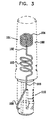
Reference is now made to FIG. 5, which is a simplified illustration of an antenna constructed and operative in accordance with a further preferred embodiment of the present invention having three coil portions, two of which are windback coil portions.
As seen in FIG. 5, there is provided within an antenna housing sleeve 200, an antenna 201 comprising an elongate portion 202, which is integrally formed upstream thereof with a coil portion 204 and is integrally formed downstream thereof with first and second windback coil portions 205 and 206. Coil portions 205 and 206 are seen to be arranged about the elongate portion 202 and in overlapping relationship therewith.
In accordance with a preferred embodiment of the present invention, there is also provided a mounting portion 207, which is integrally formed with the coil portion 204. Preferably, the mounting portion 207 includes a bent section 208 arranged for spring fit engagement with a corresponding electrical contact (not shown) of a portable communications device (not shown), which may be identical to portable communications device 30 shown in FIG. 1. Mounting portion 207 is typically seated in a housing base portion 210.
Reference is now made to FIG. 6, which is a simplified illustration of an antenna constructed and operative in accordance with yet another preferred embodiment of the present invention having four coil portions, two of which are windback coil portions.
As seen in FIG. 6, there is provided within an antenna housing sleeve 250, an antenna 251 comprising an elongate portion 252, which is integrally formed upstream thereof with first and second coil portions 253 and 254 and is integrally formed downstream thereof with first and second windback coil portions 255 and 256. Coil portions 255 and 256 are seen to be arranged about the elongate portion 252 and in overlapping relationship therewith.
In accordance with a preferred embodiment of the present invention, there is also provided a mounting portion 257, which is integrally formed with coil portion 253. Preferably, the mounting portion 257 includes a bent section 258 arranged for spring fit engagement with a corresponding electrical contact (not shown) of a portable communications device (not shown), which may be identical to portable communications device 30 shown in FIG. 1. Mounting portion 257 is typically seated in a housing base portion 260.
It is a particular feature of the present invention that multi-band and/or wide band antenna performance is provided by an antenna including a single piece conductor.
It will be appreciated by persons skilled in the art that the present invention is not limited by what has been particularly shown and described hereinabove. Rather the scope of the present invention includes both combinations and subcombinations of the various features described hereinabove as well as variations and modifications which would occur to persons skilled in the art upon reading the specification and which are not in the prior art.

Claims (20)

What is claimed is:
1. An antenna particularly suitable for a portable communication device and including:
a elongate portion integrally formed with at least one first coil portion arranged about the elongate portion and in at least partially overlapping relationship therewith,
said antenna having a single feed end and a single free end.
2. The antenna according to claim 1 and also comprising at least one second coil portion integrally formed with said elongate portion.
3. The antenna according to claim 2 and wherein said at least one second coil portion is disposed in non-overlapping relationship with said elongate portion.
4. The antenna according to claim 1 and wherein said elongate portion and said at least one first coil portion have separate resonant frequency bands.
5. The antenna according to claim 2 and wherein said elongate portion, said at least one first coil portion and said at least one second coil portion each have separate resonant frequency bands.
6. The antenna according to claim 1 and also comprising a mounting portion integrally formed with said elongate portion, said mounting portion including a bent section arranged for spring fit engagement with an electrical contact.
7. A portable communications device comprising:
a transceiver; and
an antenna connected to said transceiver and including an elongate portion integrally formed with a least one first coil portion arranged about the elongate portion and in at least partially overlapping relationship therewith, said antenna having a single feed and a single free end.
8. The portable communications device according to claim 7 and also comprising at least one second coil portion integrally formed with said elongate portion.
9. The portable communications device according to claim 8 and wherein said at least one second coil portion is disposed in non-overlapping relationship with said elongate portion.
10. The portable communications device according to claim 8 and wherein said elongate portion and said at least one first coil portion have separate resonate frequency bands.
11. The portable communications device according to claim 8 and wherein said elongate portion, said at least one first coil portion and said at least one second coil portion have separate resonate frequency bands.
12. The portable communications device according to claim 8 and also comprising a mounting portion integrally formed with said elongate portion, said mounting portion including a bent section arranged for spring fit engagement with an electrical contact.
13. The antenna according to claim 1 and wherein said at least one first coil is formed as one piece with said elongate portion.
14. The antenna according to claim 13 and wherein said at least one first coil portion extends in a wind-back configuration over at least part of said elongate portion.
15. The antenna according to claim 14 and wherein said at least one first coil portion is coaxial with said elongate portion.
16. The antenna according to claim 14 and also comprising at least one second coil portion arranged coaxially with said elongate portion and between said elongate portion and a mounting portion of said antenna.
17. A portable communication device comprising:
a transceiver; and
an antenna cooperating with said transceiver, said antenna having a single feed end and a single free end and also comprising:
an elongate portion integrally formed with at least one first coil portion arranged about the elongate portion and in at least partially overlapping relationship therewith, wherein said at least one first coil portion is formed as one piece with said elongate portion.
18. The portable communication device according to claim 17 and wherein said at least one first coil portion extends in a wind-back configuration over at least part of said elongate portion.
19. The portable communication device according to claim 18 and wherein said at least one first coil portion is coaxial with said elongate portion.
20. The portable communication device according to claim 18 and also comprising at least one second coil portion arranged coaxially with said elongate portion and between said elongate portion and a mounting portion of said antenna.
US10/110,438 1999-10-12 2000-10-06 Portable antenna Expired - Fee Related US6781549B1 (en)

Priority Applications (1)

Application Number Priority Date Filing Date Title
US10/110,438 US6781549B1 (en) 1999-10-12 2000-10-06 Portable antenna

Applications Claiming Priority (3)

Application Number Priority Date Filing Date Title
US15946199P 1999-10-12 1999-10-12
PCT/IL2000/000633 WO2001028033A1 (en) 1999-10-12 2000-10-06 Portable antenna
US10/110,438 US6781549B1 (en) 1999-10-12 2000-10-06 Portable antenna

Publications (1)

Publication Number Publication Date
US6781549B1 true US6781549B1 (en) 2004-08-24

Family

ID=32871421

Family Applications (1)

Application Number Title Priority Date Filing Date
US10/110,438 Expired - Fee Related US6781549B1 (en) 1999-10-12 2000-10-06 Portable antenna

Country Status (1)

Country Link
US (1) US6781549B1 (en)

Cited By (4)

* Cited by examiner, † Cited by third party
Publication number Priority date Publication date Assignee Title
US20020142737A1 (en) * 2001-03-28 2002-10-03 Takashi Amano Mobile communication terminal
WO2006121627A2 (en) * 2005-05-06 2006-11-16 Motorola, Inc. Antenna apparatus and method of forming same
US20080106485A1 (en) * 2006-11-07 2008-05-08 Wistron Neweb Corp. Portable electronic device and antenna thereof
US20140253410A1 (en) * 2013-03-05 2014-09-11 Carlo Dinallo Multi-mode, multi-band antenna

Citations (33)

* Cited by examiner, † Cited by third party
Publication number Priority date Publication date Assignee Title
US3852759A (en) * 1960-04-01 1974-12-03 Itt Broadband tunable antenna
US4161737A (en) 1977-10-03 1979-07-17 Albright Eugene A Helical antenna
US4229743A (en) 1978-09-22 1980-10-21 Shakespeare Company Multiple band, multiple resonant frequency antenna
US4442438A (en) * 1982-03-29 1984-04-10 Motorola, Inc. Helical antenna structure capable of resonating at two different frequencies
US4644366A (en) 1984-09-26 1987-02-17 Amitec, Inc. Miniature radio transceiver antenna
US4772895A (en) 1987-06-15 1988-09-20 Motorola, Inc. Wide-band helical antenna
US5359340A (en) 1992-09-30 1994-10-25 Fujitsu Limited Helical antenna for portable radio communication equipment
US5374937A (en) * 1991-07-08 1994-12-20 Nippon Telegraph And Telephone Corporation Retractable antenna system
US5469177A (en) 1993-09-15 1995-11-21 Motorola, Inc. Antenna assembly and method therefor
US5521605A (en) 1990-02-23 1996-05-28 Kabushiki Kaisha Toshiba Extendable antenna for a radio transceiver
US5592184A (en) 1991-08-16 1997-01-07 Telefonaktiebolaget Lm Ericsson Miniature antenna
US5600341A (en) 1995-08-21 1997-02-04 Motorola, Inc. Dual function antenna structure and a portable radio having same
US5668559A (en) 1993-10-14 1997-09-16 Alcatel Mobile Communication France Antenna for portable radio devices
US5686927A (en) 1995-11-03 1997-11-11 Centurion International, Inc. Retractable antenna
US5754146A (en) 1995-04-26 1998-05-19 Westinghouse Electric Corporation Helical antenna having a parasitic element and method of using same
US5805112A (en) 1993-07-14 1998-09-08 Ericsson Inc. Extra antenna element
US5808586A (en) 1997-02-19 1998-09-15 Motorola, Inc. Side-by-side coil-fed antenna for a portable radio
US5812097A (en) 1996-04-30 1998-09-22 Qualcomm Incorporated Dual band antenna
US5923305A (en) 1997-09-15 1999-07-13 Ericsson Inc. Dual-band helix antenna with parasitic element and associated methods of operation
US5963170A (en) 1997-05-22 1999-10-05 Lucent Technologies Inc. Fixed dual frequency band antenna
US5990847A (en) 1996-04-30 1999-11-23 Qualcomm Incorporated Coupled multi-segment helical antenna
US6005523A (en) 1997-12-11 1999-12-21 Ericsson Inc. Antenna rod disconnect mechanisms and associated methods
US6016130A (en) 1996-08-22 2000-01-18 Lk-Products Oy Dual-frequency antenna
US6052090A (en) 1997-08-26 2000-04-18 Centurion International, Inc. Multi-band antenna
US6054959A (en) 1998-04-03 2000-04-25 Nortel Networks Corporation Dual resonant antenna
US6054962A (en) 1997-07-19 2000-04-25 Samsung Electronics Co. Ltd. Dual band antenna
US6054966A (en) * 1995-06-06 2000-04-25 Nokia Mobile Phones Limited Antenna operating in two frequency ranges
US6069592A (en) 1996-06-15 2000-05-30 Allgon Ab Meander antenna device
US6075488A (en) 1997-04-29 2000-06-13 Galtronics Ltd. Dual-band stub antenna
US6094179A (en) 1997-11-04 2000-07-25 Nokia Mobile Phones Limited Antenna
US6097341A (en) 1997-05-07 2000-08-01 Nec Corporation Structure of an antenna for a portable radio communication apparatus
US6111545A (en) 1992-01-23 2000-08-29 Nokia Mobile Phones, Ltd. Antenna
US6115000A (en) 1997-07-16 2000-09-05 Tokin Corporation Antenna assembly comprising whip antenna and helical antenna contained in antenna top rotatably mounted on top end of the whip antenna

Patent Citations (33)

* Cited by examiner, † Cited by third party
Publication number Priority date Publication date Assignee Title
US3852759A (en) * 1960-04-01 1974-12-03 Itt Broadband tunable antenna
US4161737A (en) 1977-10-03 1979-07-17 Albright Eugene A Helical antenna
US4229743A (en) 1978-09-22 1980-10-21 Shakespeare Company Multiple band, multiple resonant frequency antenna
US4442438A (en) * 1982-03-29 1984-04-10 Motorola, Inc. Helical antenna structure capable of resonating at two different frequencies
US4644366A (en) 1984-09-26 1987-02-17 Amitec, Inc. Miniature radio transceiver antenna
US4772895A (en) 1987-06-15 1988-09-20 Motorola, Inc. Wide-band helical antenna
US5521605A (en) 1990-02-23 1996-05-28 Kabushiki Kaisha Toshiba Extendable antenna for a radio transceiver
US5374937A (en) * 1991-07-08 1994-12-20 Nippon Telegraph And Telephone Corporation Retractable antenna system
US5592184A (en) 1991-08-16 1997-01-07 Telefonaktiebolaget Lm Ericsson Miniature antenna
US6111545A (en) 1992-01-23 2000-08-29 Nokia Mobile Phones, Ltd. Antenna
US5359340A (en) 1992-09-30 1994-10-25 Fujitsu Limited Helical antenna for portable radio communication equipment
US5805112A (en) 1993-07-14 1998-09-08 Ericsson Inc. Extra antenna element
US5469177A (en) 1993-09-15 1995-11-21 Motorola, Inc. Antenna assembly and method therefor
US5668559A (en) 1993-10-14 1997-09-16 Alcatel Mobile Communication France Antenna for portable radio devices
US5754146A (en) 1995-04-26 1998-05-19 Westinghouse Electric Corporation Helical antenna having a parasitic element and method of using same
US6054966A (en) * 1995-06-06 2000-04-25 Nokia Mobile Phones Limited Antenna operating in two frequency ranges
US5600341A (en) 1995-08-21 1997-02-04 Motorola, Inc. Dual function antenna structure and a portable radio having same
US5686927A (en) 1995-11-03 1997-11-11 Centurion International, Inc. Retractable antenna
US5812097A (en) 1996-04-30 1998-09-22 Qualcomm Incorporated Dual band antenna
US5990847A (en) 1996-04-30 1999-11-23 Qualcomm Incorporated Coupled multi-segment helical antenna
US6069592A (en) 1996-06-15 2000-05-30 Allgon Ab Meander antenna device
US6016130A (en) 1996-08-22 2000-01-18 Lk-Products Oy Dual-frequency antenna
US5808586A (en) 1997-02-19 1998-09-15 Motorola, Inc. Side-by-side coil-fed antenna for a portable radio
US6075488A (en) 1997-04-29 2000-06-13 Galtronics Ltd. Dual-band stub antenna
US6097341A (en) 1997-05-07 2000-08-01 Nec Corporation Structure of an antenna for a portable radio communication apparatus
US5963170A (en) 1997-05-22 1999-10-05 Lucent Technologies Inc. Fixed dual frequency band antenna
US6115000A (en) 1997-07-16 2000-09-05 Tokin Corporation Antenna assembly comprising whip antenna and helical antenna contained in antenna top rotatably mounted on top end of the whip antenna
US6054962A (en) 1997-07-19 2000-04-25 Samsung Electronics Co. Ltd. Dual band antenna
US6052090A (en) 1997-08-26 2000-04-18 Centurion International, Inc. Multi-band antenna
US5923305A (en) 1997-09-15 1999-07-13 Ericsson Inc. Dual-band helix antenna with parasitic element and associated methods of operation
US6094179A (en) 1997-11-04 2000-07-25 Nokia Mobile Phones Limited Antenna
US6005523A (en) 1997-12-11 1999-12-21 Ericsson Inc. Antenna rod disconnect mechanisms and associated methods
US6054959A (en) 1998-04-03 2000-04-25 Nortel Networks Corporation Dual resonant antenna

Cited By (8)

* Cited by examiner, † Cited by third party
Publication number Priority date Publication date Assignee Title
US20020142737A1 (en) * 2001-03-28 2002-10-03 Takashi Amano Mobile communication terminal
WO2006121627A2 (en) * 2005-05-06 2006-11-16 Motorola, Inc. Antenna apparatus and method of forming same
WO2006121627A3 (en) * 2005-05-06 2007-05-24 Motorola Inc Antenna apparatus and method of forming same
GB2441685A (en) * 2005-05-06 2008-03-12 Motorola Inc Antenna apparatus and method of forming same
GB2441685B (en) * 2005-05-06 2009-09-02 Motorola Inc Antenna apparatus and method of forming same
US20080106485A1 (en) * 2006-11-07 2008-05-08 Wistron Neweb Corp. Portable electronic device and antenna thereof
US20140253410A1 (en) * 2013-03-05 2014-09-11 Carlo Dinallo Multi-mode, multi-band antenna
US10038235B2 (en) * 2013-03-05 2018-07-31 Maxtena, Inc. Multi-mode, multi-band antenna

Similar Documents

Publication Publication Date Title
KR100637346B1 (en) Antenna system for a radio communication device
US6417816B2 (en) Dual band bowtie/meander antenna
US7226293B2 (en) Built-in type antenna assembly of wireless communication terminal
US6801166B2 (en) Planar antenna
FI112984B (en) Internal antenna
JP4301034B2 (en) Wireless device with antenna
EP1849212A2 (en) Multiple monopole antenna
WO2002039540A3 (en) Multiband, single feed antenna
US6448934B1 (en) Multi band antenna
CN101740859B (en) Multi-band antenna
KR20010075127A (en) Antenna which can be operated in several frequency bands
WO2003034539A1 (en) Dielectric antenna
CN101283482A (en) Subminiature internal antenna
JPH06188805A (en) Radio equipment
US6781549B1 (en) Portable antenna
JP2004512756A (en) Broadband built-in antenna
WO2001028033A1 (en) Portable antenna
US20050219128A1 (en) Antenna radiator assembly and radio communications device
US6781552B2 (en) Built-in multi-band mobile phone antenna assembly with coplanar patch antenna and loop antenna
EP1267439B1 (en) Multiple frequency bands antenna using two concentric interleaved antennas, the external one being a meander line antenna
US20090278751A1 (en) Antenna Device and Portable Terminal Device
US6232930B1 (en) Dual band antenna and method of making same
US20040246185A1 (en) Multi-band improvements to a monopole helical
US7446726B2 (en) Antenna
JP2002515212A (en) Multi-band flexible antenna

Legal Events

Date Code Title Description
AS Assignment

Owner name: GALTRONICS LTD., ISRAEL

Free format text: ASSIGNMENT OF ASSIGNORS INTEREST;ASSIGNORS:MACQUEEN, ANGUS;BERIN, ALEXANDER;REEL/FRAME:013124/0031;SIGNING DATES FROM 20020520 TO 20020618

FPAY Fee payment

Year of fee payment: 4

FEPP Fee payment procedure

Free format text: PAYOR NUMBER ASSIGNED (ORIGINAL EVENT CODE: ASPN); ENTITY STATUS OF PATENT OWNER: LARGE ENTITY

FPAY Fee payment

Year of fee payment: 8

SULP Surcharge for late payment

Year of fee payment: 7

REMI Maintenance fee reminder mailed
LAPS Lapse for failure to pay maintenance fees
STCH Information on status: patent discontinuation

Free format text: PATENT EXPIRED DUE TO NONPAYMENT OF MAINTENANCE FEES UNDER 37 CFR 1.362

FP Lapsed due to failure to pay maintenance fee

Effective date: 20160824