US6777759B1 - Device structure and method for reducing silicide encroachment - Google Patents
Device structure and method for reducing silicide encroachment Download PDFInfo
- Publication number
- US6777759B1 US6777759B1 US09/654,315 US65431500A US6777759B1 US 6777759 B1 US6777759 B1 US 6777759B1 US 65431500 A US65431500 A US 65431500A US 6777759 B1 US6777759 B1 US 6777759B1
- Authority
- US
- United States
- Prior art keywords
- silicide
- source
- layer
- gate electrode
- substrate
- Prior art date
- Legal status (The legal status is an assumption and is not a legal conclusion. Google has not performed a legal analysis and makes no representation as to the accuracy of the status listed.)
- Expired - Lifetime
Links
- FVBUAEGBCNSCDD-UHFFFAOYSA-N silicide(4-) Chemical compound [Si-4] FVBUAEGBCNSCDD-UHFFFAOYSA-N 0.000 title claims abstract description 120
- 229910021332 silicide Inorganic materials 0.000 title claims abstract description 103
- 238000000034 method Methods 0.000 title description 49
- 125000006850 spacer group Chemical group 0.000 claims abstract description 47
- 239000004065 semiconductor Substances 0.000 claims abstract description 33
- 239000000758 substrate Substances 0.000 claims description 55
- 238000002955 isolation Methods 0.000 claims description 54
- 229910021420 polycrystalline silicon Inorganic materials 0.000 claims description 38
- 229920005591 polysilicon Polymers 0.000 claims description 37
- 229910000577 Silicon-germanium Inorganic materials 0.000 claims description 11
- LEVVHYCKPQWKOP-UHFFFAOYSA-N [Si].[Ge] Chemical compound [Si].[Ge] LEVVHYCKPQWKOP-UHFFFAOYSA-N 0.000 claims description 11
- 238000004519 manufacturing process Methods 0.000 abstract description 8
- XUIMIQQOPSSXEZ-UHFFFAOYSA-N Silicon Chemical compound [Si] XUIMIQQOPSSXEZ-UHFFFAOYSA-N 0.000 description 22
- 229910052710 silicon Inorganic materials 0.000 description 22
- 239000010703 silicon Substances 0.000 description 22
- 229910052751 metal Inorganic materials 0.000 description 17
- 239000002184 metal Substances 0.000 description 17
- 230000015572 biosynthetic process Effects 0.000 description 16
- 239000000463 material Substances 0.000 description 16
- 238000000151 deposition Methods 0.000 description 9
- 229910052581 Si3N4 Inorganic materials 0.000 description 8
- 238000006243 chemical reaction Methods 0.000 description 7
- HQVNEWCFYHHQES-UHFFFAOYSA-N silicon nitride Chemical compound N12[Si]34N5[Si]62N3[Si]51N64 HQVNEWCFYHHQES-UHFFFAOYSA-N 0.000 description 7
- PXHVJJICTQNCMI-UHFFFAOYSA-N Nickel Chemical compound [Ni] PXHVJJICTQNCMI-UHFFFAOYSA-N 0.000 description 6
- 230000000694 effects Effects 0.000 description 6
- 238000000206 photolithography Methods 0.000 description 6
- 238000005229 chemical vapour deposition Methods 0.000 description 5
- 230000008021 deposition Effects 0.000 description 5
- 238000005530 etching Methods 0.000 description 5
- KDLHZDBZIXYQEI-UHFFFAOYSA-N Palladium Chemical compound [Pd] KDLHZDBZIXYQEI-UHFFFAOYSA-N 0.000 description 4
- VYPSYNLAJGMNEJ-UHFFFAOYSA-N Silicium dioxide Chemical compound O=[Si]=O VYPSYNLAJGMNEJ-UHFFFAOYSA-N 0.000 description 4
- QAOWNCQODCNURD-UHFFFAOYSA-N Sulfuric acid Chemical compound OS(O)(=O)=O QAOWNCQODCNURD-UHFFFAOYSA-N 0.000 description 3
- 239000002019 doping agent Substances 0.000 description 3
- 150000002500 ions Chemical class 0.000 description 3
- 229910044991 metal oxide Inorganic materials 0.000 description 3
- 150000004706 metal oxides Chemical class 0.000 description 3
- 229910052759 nickel Inorganic materials 0.000 description 3
- 229910003818 SiH2Cl2 Inorganic materials 0.000 description 2
- RTAQQCXQSZGOHL-UHFFFAOYSA-N Titanium Chemical compound [Ti] RTAQQCXQSZGOHL-UHFFFAOYSA-N 0.000 description 2
- 229910045601 alloy Inorganic materials 0.000 description 2
- 239000000956 alloy Substances 0.000 description 2
- 239000003990 capacitor Substances 0.000 description 2
- 229910017052 cobalt Inorganic materials 0.000 description 2
- 239000010941 cobalt Substances 0.000 description 2
- GUTLYIVDDKVIGB-UHFFFAOYSA-N cobalt atom Chemical compound [Co] GUTLYIVDDKVIGB-UHFFFAOYSA-N 0.000 description 2
- 230000005574 cross-species transmission Effects 0.000 description 2
- 229910052732 germanium Inorganic materials 0.000 description 2
- GNPVGFCGXDBREM-UHFFFAOYSA-N germanium atom Chemical compound [Ge] GNPVGFCGXDBREM-UHFFFAOYSA-N 0.000 description 2
- 238000005468 ion implantation Methods 0.000 description 2
- 229910021334 nickel silicide Inorganic materials 0.000 description 2
- RUFLMLWJRZAWLJ-UHFFFAOYSA-N nickel silicide Chemical compound [Ni]=[Si]=[Ni] RUFLMLWJRZAWLJ-UHFFFAOYSA-N 0.000 description 2
- 229910052763 palladium Inorganic materials 0.000 description 2
- 238000001020 plasma etching Methods 0.000 description 2
- 238000005498 polishing Methods 0.000 description 2
- 239000003870 refractory metal Substances 0.000 description 2
- 235000012239 silicon dioxide Nutrition 0.000 description 2
- 239000000377 silicon dioxide Substances 0.000 description 2
- 229910052719 titanium Inorganic materials 0.000 description 2
- 239000010936 titanium Substances 0.000 description 2
- 229910021341 titanium silicide Inorganic materials 0.000 description 2
- WFKWXMTUELFFGS-UHFFFAOYSA-N tungsten Chemical compound [W] WFKWXMTUELFFGS-UHFFFAOYSA-N 0.000 description 2
- 229910052721 tungsten Inorganic materials 0.000 description 2
- 239000010937 tungsten Substances 0.000 description 2
- VHUUQVKOLVNVRT-UHFFFAOYSA-N Ammonium hydroxide Chemical compound [NH4+].[OH-] VHUUQVKOLVNVRT-UHFFFAOYSA-N 0.000 description 1
- JBRZTFJDHDCESZ-UHFFFAOYSA-N AsGa Chemical compound [As]#[Ga] JBRZTFJDHDCESZ-UHFFFAOYSA-N 0.000 description 1
- ZOXJGFHDIHLPTG-UHFFFAOYSA-N Boron Chemical compound [B] ZOXJGFHDIHLPTG-UHFFFAOYSA-N 0.000 description 1
- PXGOKWXKJXAPGV-UHFFFAOYSA-N Fluorine Chemical compound FF PXGOKWXKJXAPGV-UHFFFAOYSA-N 0.000 description 1
- 229910001218 Gallium arsenide Inorganic materials 0.000 description 1
- UFHFLCQGNIYNRP-UHFFFAOYSA-N Hydrogen Chemical compound [H][H] UFHFLCQGNIYNRP-UHFFFAOYSA-N 0.000 description 1
- BLRPTPMANUNPDV-UHFFFAOYSA-N Silane Chemical compound [SiH4] BLRPTPMANUNPDV-UHFFFAOYSA-N 0.000 description 1
- 229910003074 TiCl4 Inorganic materials 0.000 description 1
- 229910021417 amorphous silicon Inorganic materials 0.000 description 1
- 229910052796 boron Inorganic materials 0.000 description 1
- -1 but not limited to Substances 0.000 description 1
- 239000012159 carrier gas Substances 0.000 description 1
- 230000000295 complement effect Effects 0.000 description 1
- 239000002131 composite material Substances 0.000 description 1
- 230000008878 coupling Effects 0.000 description 1
- 238000010168 coupling process Methods 0.000 description 1
- 238000005859 coupling reaction Methods 0.000 description 1
- 238000000354 decomposition reaction Methods 0.000 description 1
- 238000005137 deposition process Methods 0.000 description 1
- 238000009792 diffusion process Methods 0.000 description 1
- 239000011737 fluorine Substances 0.000 description 1
- 229910052731 fluorine Inorganic materials 0.000 description 1
- QUZPNFFHZPRKJD-UHFFFAOYSA-N germane Chemical compound [GeH4] QUZPNFFHZPRKJD-UHFFFAOYSA-N 0.000 description 1
- 229910052986 germanium hydride Inorganic materials 0.000 description 1
- BHEPBYXIRTUNPN-UHFFFAOYSA-N hydridophosphorus(.) (triplet) Chemical compound [PH] BHEPBYXIRTUNPN-UHFFFAOYSA-N 0.000 description 1
- 239000001257 hydrogen Substances 0.000 description 1
- 229910052739 hydrogen Inorganic materials 0.000 description 1
- 239000007943 implant Substances 0.000 description 1
- 238000002513 implantation Methods 0.000 description 1
- 239000012212 insulator Substances 0.000 description 1
- 230000000873 masking effect Effects 0.000 description 1
- 239000000203 mixture Substances 0.000 description 1
- PEUPIGGLJVUNEU-UHFFFAOYSA-N nickel silicon Chemical compound [Si].[Ni] PEUPIGGLJVUNEU-UHFFFAOYSA-N 0.000 description 1
- 150000004767 nitrides Chemical class 0.000 description 1
- 238000012856 packing Methods 0.000 description 1
- 238000005389 semiconductor device fabrication Methods 0.000 description 1
- 239000007787 solid Substances 0.000 description 1
- 238000004544 sputter deposition Methods 0.000 description 1
- 239000007858 starting material Substances 0.000 description 1
- 239000000126 substance Substances 0.000 description 1
- XJDNKRIXUMDJCW-UHFFFAOYSA-J titanium tetrachloride Chemical compound Cl[Ti](Cl)(Cl)Cl XJDNKRIXUMDJCW-UHFFFAOYSA-J 0.000 description 1
Images


Classifications
-
- H—ELECTRICITY
- H01—ELECTRIC ELEMENTS
- H01L—SEMICONDUCTOR DEVICES NOT COVERED BY CLASS H10
- H01L29/00—Semiconductor devices adapted for rectifying, amplifying, oscillating or switching, or capacitors or resistors with at least one potential-jump barrier or surface barrier, e.g. PN junction depletion layer or carrier concentration layer; Details of semiconductor bodies or of electrodes thereof ; Multistep manufacturing processes therefor
- H01L29/66—Types of semiconductor device ; Multistep manufacturing processes therefor
- H01L29/66007—Multistep manufacturing processes
- H01L29/66075—Multistep manufacturing processes of devices having semiconductor bodies comprising group 14 or group 13/15 materials
- H01L29/66227—Multistep manufacturing processes of devices having semiconductor bodies comprising group 14 or group 13/15 materials the devices being controllable only by the electric current supplied or the electric potential applied, to an electrode which does not carry the current to be rectified, amplified or switched, e.g. three-terminal devices
- H01L29/66409—Unipolar field-effect transistors
- H01L29/66477—Unipolar field-effect transistors with an insulated gate, i.e. MISFET
- H01L29/66515—Unipolar field-effect transistors with an insulated gate, i.e. MISFET using self aligned selective metal deposition simultaneously on the gate and on source or drain
-
- H—ELECTRICITY
- H01—ELECTRIC ELEMENTS
- H01L—SEMICONDUCTOR DEVICES NOT COVERED BY CLASS H10
- H01L21/00—Processes or apparatus adapted for the manufacture or treatment of semiconductor or solid state devices or of parts thereof
- H01L21/02—Manufacture or treatment of semiconductor devices or of parts thereof
- H01L21/04—Manufacture or treatment of semiconductor devices or of parts thereof the devices having at least one potential-jump barrier or surface barrier, e.g. PN junction, depletion layer or carrier concentration layer
- H01L21/18—Manufacture or treatment of semiconductor devices or of parts thereof the devices having at least one potential-jump barrier or surface barrier, e.g. PN junction, depletion layer or carrier concentration layer the devices having semiconductor bodies comprising elements of Group IV of the Periodic System or AIIIBV compounds with or without impurities, e.g. doping materials
- H01L21/28—Manufacture of electrodes on semiconductor bodies using processes or apparatus not provided for in groups H01L21/20 - H01L21/268
- H01L21/283—Deposition of conductive or insulating materials for electrodes conducting electric current
- H01L21/285—Deposition of conductive or insulating materials for electrodes conducting electric current from a gas or vapour, e.g. condensation
- H01L21/28506—Deposition of conductive or insulating materials for electrodes conducting electric current from a gas or vapour, e.g. condensation of conductive layers
- H01L21/28512—Deposition of conductive or insulating materials for electrodes conducting electric current from a gas or vapour, e.g. condensation of conductive layers on semiconductor bodies comprising elements of Group IV of the Periodic System
- H01L21/28525—Deposition of conductive or insulating materials for electrodes conducting electric current from a gas or vapour, e.g. condensation of conductive layers on semiconductor bodies comprising elements of Group IV of the Periodic System the conductive layers comprising semiconducting material
-
- H—ELECTRICITY
- H01—ELECTRIC ELEMENTS
- H01L—SEMICONDUCTOR DEVICES NOT COVERED BY CLASS H10
- H01L21/00—Processes or apparatus adapted for the manufacture or treatment of semiconductor or solid state devices or of parts thereof
- H01L21/02—Manufacture or treatment of semiconductor devices or of parts thereof
- H01L21/04—Manufacture or treatment of semiconductor devices or of parts thereof the devices having at least one potential-jump barrier or surface barrier, e.g. PN junction, depletion layer or carrier concentration layer
- H01L21/18—Manufacture or treatment of semiconductor devices or of parts thereof the devices having at least one potential-jump barrier or surface barrier, e.g. PN junction, depletion layer or carrier concentration layer the devices having semiconductor bodies comprising elements of Group IV of the Periodic System or AIIIBV compounds with or without impurities, e.g. doping materials
- H01L21/28—Manufacture of electrodes on semiconductor bodies using processes or apparatus not provided for in groups H01L21/20 - H01L21/268
- H01L21/283—Deposition of conductive or insulating materials for electrodes conducting electric current
- H01L21/285—Deposition of conductive or insulating materials for electrodes conducting electric current from a gas or vapour, e.g. condensation
- H01L21/28506—Deposition of conductive or insulating materials for electrodes conducting electric current from a gas or vapour, e.g. condensation of conductive layers
- H01L21/28512—Deposition of conductive or insulating materials for electrodes conducting electric current from a gas or vapour, e.g. condensation of conductive layers on semiconductor bodies comprising elements of Group IV of the Periodic System
- H01L21/28556—Deposition of conductive or insulating materials for electrodes conducting electric current from a gas or vapour, e.g. condensation of conductive layers on semiconductor bodies comprising elements of Group IV of the Periodic System by chemical means, e.g. CVD, LPCVD, PECVD, laser CVD
- H01L21/28562—Selective deposition
-
- H—ELECTRICITY
- H01—ELECTRIC ELEMENTS
- H01L—SEMICONDUCTOR DEVICES NOT COVERED BY CLASS H10
- H01L21/00—Processes or apparatus adapted for the manufacture or treatment of semiconductor or solid state devices or of parts thereof
- H01L21/70—Manufacture or treatment of devices consisting of a plurality of solid state components formed in or on a common substrate or of parts thereof; Manufacture of integrated circuit devices or of parts thereof
- H01L21/77—Manufacture or treatment of devices consisting of a plurality of solid state components or integrated circuits formed in, or on, a common substrate
- H01L21/78—Manufacture or treatment of devices consisting of a plurality of solid state components or integrated circuits formed in, or on, a common substrate with subsequent division of the substrate into plural individual devices
- H01L21/82—Manufacture or treatment of devices consisting of a plurality of solid state components or integrated circuits formed in, or on, a common substrate with subsequent division of the substrate into plural individual devices to produce devices, e.g. integrated circuits, each consisting of a plurality of components
- H01L21/822—Manufacture or treatment of devices consisting of a plurality of solid state components or integrated circuits formed in, or on, a common substrate with subsequent division of the substrate into plural individual devices to produce devices, e.g. integrated circuits, each consisting of a plurality of components the substrate being a semiconductor, using silicon technology
- H01L21/8232—Field-effect technology
- H01L21/8234—MIS technology, i.e. integration processes of field effect transistors of the conductor-insulator-semiconductor type
- H01L21/8238—Complementary field-effect transistors, e.g. CMOS
- H01L21/823814—Complementary field-effect transistors, e.g. CMOS with a particular manufacturing method of the source or drain structures, e.g. specific source or drain implants or silicided source or drain structures or raised source or drain structures
-
- H—ELECTRICITY
- H01—ELECTRIC ELEMENTS
- H01L—SEMICONDUCTOR DEVICES NOT COVERED BY CLASS H10
- H01L21/00—Processes or apparatus adapted for the manufacture or treatment of semiconductor or solid state devices or of parts thereof
- H01L21/70—Manufacture or treatment of devices consisting of a plurality of solid state components formed in or on a common substrate or of parts thereof; Manufacture of integrated circuit devices or of parts thereof
- H01L21/77—Manufacture or treatment of devices consisting of a plurality of solid state components or integrated circuits formed in, or on, a common substrate
- H01L21/78—Manufacture or treatment of devices consisting of a plurality of solid state components or integrated circuits formed in, or on, a common substrate with subsequent division of the substrate into plural individual devices
- H01L21/82—Manufacture or treatment of devices consisting of a plurality of solid state components or integrated circuits formed in, or on, a common substrate with subsequent division of the substrate into plural individual devices to produce devices, e.g. integrated circuits, each consisting of a plurality of components
- H01L21/822—Manufacture or treatment of devices consisting of a plurality of solid state components or integrated circuits formed in, or on, a common substrate with subsequent division of the substrate into plural individual devices to produce devices, e.g. integrated circuits, each consisting of a plurality of components the substrate being a semiconductor, using silicon technology
- H01L21/8232—Field-effect technology
- H01L21/8234—MIS technology, i.e. integration processes of field effect transistors of the conductor-insulator-semiconductor type
- H01L21/8238—Complementary field-effect transistors, e.g. CMOS
- H01L21/823828—Complementary field-effect transistors, e.g. CMOS with a particular manufacturing method of the gate conductors, e.g. particular materials, shapes
- H01L21/823835—Complementary field-effect transistors, e.g. CMOS with a particular manufacturing method of the gate conductors, e.g. particular materials, shapes silicided or salicided gate conductors
-
- H—ELECTRICITY
- H01—ELECTRIC ELEMENTS
- H01L—SEMICONDUCTOR DEVICES NOT COVERED BY CLASS H10
- H01L21/00—Processes or apparatus adapted for the manufacture or treatment of semiconductor or solid state devices or of parts thereof
- H01L21/70—Manufacture or treatment of devices consisting of a plurality of solid state components formed in or on a common substrate or of parts thereof; Manufacture of integrated circuit devices or of parts thereof
- H01L21/77—Manufacture or treatment of devices consisting of a plurality of solid state components or integrated circuits formed in, or on, a common substrate
- H01L21/78—Manufacture or treatment of devices consisting of a plurality of solid state components or integrated circuits formed in, or on, a common substrate with subsequent division of the substrate into plural individual devices
- H01L21/82—Manufacture or treatment of devices consisting of a plurality of solid state components or integrated circuits formed in, or on, a common substrate with subsequent division of the substrate into plural individual devices to produce devices, e.g. integrated circuits, each consisting of a plurality of components
- H01L21/822—Manufacture or treatment of devices consisting of a plurality of solid state components or integrated circuits formed in, or on, a common substrate with subsequent division of the substrate into plural individual devices to produce devices, e.g. integrated circuits, each consisting of a plurality of components the substrate being a semiconductor, using silicon technology
- H01L21/8232—Field-effect technology
- H01L21/8234—MIS technology, i.e. integration processes of field effect transistors of the conductor-insulator-semiconductor type
- H01L21/8238—Complementary field-effect transistors, e.g. CMOS
- H01L21/823878—Complementary field-effect transistors, e.g. CMOS isolation region manufacturing related aspects, e.g. to avoid interaction of isolation region with adjacent structure
-
- H—ELECTRICITY
- H01—ELECTRIC ELEMENTS
- H01L—SEMICONDUCTOR DEVICES NOT COVERED BY CLASS H10
- H01L29/00—Semiconductor devices adapted for rectifying, amplifying, oscillating or switching, or capacitors or resistors with at least one potential-jump barrier or surface barrier, e.g. PN junction depletion layer or carrier concentration layer; Details of semiconductor bodies or of electrodes thereof ; Multistep manufacturing processes therefor
- H01L29/40—Electrodes ; Multistep manufacturing processes therefor
- H01L29/41—Electrodes ; Multistep manufacturing processes therefor characterised by their shape, relative sizes or dispositions
- H01L29/417—Electrodes ; Multistep manufacturing processes therefor characterised by their shape, relative sizes or dispositions carrying the current to be rectified, amplified or switched
- H01L29/41725—Source or drain electrodes for field effect devices
- H01L29/41766—Source or drain electrodes for field effect devices with at least part of the source or drain electrode having contact below the semiconductor surface, e.g. the source or drain electrode formed at least partially in a groove or with inclusions of conductor inside the semiconductor
-
- H—ELECTRICITY
- H01—ELECTRIC ELEMENTS
- H01L—SEMICONDUCTOR DEVICES NOT COVERED BY CLASS H10
- H01L29/00—Semiconductor devices adapted for rectifying, amplifying, oscillating or switching, or capacitors or resistors with at least one potential-jump barrier or surface barrier, e.g. PN junction depletion layer or carrier concentration layer; Details of semiconductor bodies or of electrodes thereof ; Multistep manufacturing processes therefor
- H01L29/40—Electrodes ; Multistep manufacturing processes therefor
- H01L29/41—Electrodes ; Multistep manufacturing processes therefor characterised by their shape, relative sizes or dispositions
- H01L29/417—Electrodes ; Multistep manufacturing processes therefor characterised by their shape, relative sizes or dispositions carrying the current to be rectified, amplified or switched
- H01L29/41725—Source or drain electrodes for field effect devices
- H01L29/41775—Source or drain electrodes for field effect devices characterised by the proximity or the relative position of the source or drain electrode and the gate electrode, e.g. the source or drain electrode separated from the gate electrode by side-walls or spreading around or above the gate electrode
- H01L29/41783—Raised source or drain electrodes self aligned with the gate
-
- H—ELECTRICITY
- H01—ELECTRIC ELEMENTS
- H01L—SEMICONDUCTOR DEVICES NOT COVERED BY CLASS H10
- H01L29/00—Semiconductor devices adapted for rectifying, amplifying, oscillating or switching, or capacitors or resistors with at least one potential-jump barrier or surface barrier, e.g. PN junction depletion layer or carrier concentration layer; Details of semiconductor bodies or of electrodes thereof ; Multistep manufacturing processes therefor
- H01L29/66—Types of semiconductor device ; Multistep manufacturing processes therefor
- H01L29/66007—Multistep manufacturing processes
- H01L29/66075—Multistep manufacturing processes of devices having semiconductor bodies comprising group 14 or group 13/15 materials
- H01L29/66227—Multistep manufacturing processes of devices having semiconductor bodies comprising group 14 or group 13/15 materials the devices being controllable only by the electric current supplied or the electric potential applied, to an electrode which does not carry the current to be rectified, amplified or switched, e.g. three-terminal devices
- H01L29/66409—Unipolar field-effect transistors
- H01L29/66477—Unipolar field-effect transistors with an insulated gate, i.e. MISFET
- H01L29/665—Unipolar field-effect transistors with an insulated gate, i.e. MISFET using self aligned silicidation, i.e. salicide
-
- H—ELECTRICITY
- H01—ELECTRIC ELEMENTS
- H01L—SEMICONDUCTOR DEVICES NOT COVERED BY CLASS H10
- H01L29/00—Semiconductor devices adapted for rectifying, amplifying, oscillating or switching, or capacitors or resistors with at least one potential-jump barrier or surface barrier, e.g. PN junction depletion layer or carrier concentration layer; Details of semiconductor bodies or of electrodes thereof ; Multistep manufacturing processes therefor
- H01L29/66—Types of semiconductor device ; Multistep manufacturing processes therefor
- H01L29/66007—Multistep manufacturing processes
- H01L29/66075—Multistep manufacturing processes of devices having semiconductor bodies comprising group 14 or group 13/15 materials
- H01L29/66227—Multistep manufacturing processes of devices having semiconductor bodies comprising group 14 or group 13/15 materials the devices being controllable only by the electric current supplied or the electric potential applied, to an electrode which does not carry the current to be rectified, amplified or switched, e.g. three-terminal devices
- H01L29/66409—Unipolar field-effect transistors
- H01L29/66477—Unipolar field-effect transistors with an insulated gate, i.e. MISFET
- H01L29/66545—Unipolar field-effect transistors with an insulated gate, i.e. MISFET using a dummy, i.e. replacement gate in a process wherein at least a part of the final gate is self aligned to the dummy gate
-
- H—ELECTRICITY
- H01—ELECTRIC ELEMENTS
- H01L—SEMICONDUCTOR DEVICES NOT COVERED BY CLASS H10
- H01L29/00—Semiconductor devices adapted for rectifying, amplifying, oscillating or switching, or capacitors or resistors with at least one potential-jump barrier or surface barrier, e.g. PN junction depletion layer or carrier concentration layer; Details of semiconductor bodies or of electrodes thereof ; Multistep manufacturing processes therefor
- H01L29/66—Types of semiconductor device ; Multistep manufacturing processes therefor
- H01L29/66007—Multistep manufacturing processes
- H01L29/66075—Multistep manufacturing processes of devices having semiconductor bodies comprising group 14 or group 13/15 materials
- H01L29/66227—Multistep manufacturing processes of devices having semiconductor bodies comprising group 14 or group 13/15 materials the devices being controllable only by the electric current supplied or the electric potential applied, to an electrode which does not carry the current to be rectified, amplified or switched, e.g. three-terminal devices
- H01L29/66409—Unipolar field-effect transistors
- H01L29/66477—Unipolar field-effect transistors with an insulated gate, i.e. MISFET
- H01L29/66568—Lateral single gate silicon transistors
- H01L29/66636—Lateral single gate silicon transistors with source or drain recessed by etching or first recessed by etching and then refilled
Definitions
- the present invention relates to the field of semiconductor device fabrication, and more specifically to a method and structure for reducing silicide encroachment in an integrated circuit.
- Today integrated circuits are made up of literally millions of active and passive devices such as transistors, capacitors, and resistors.
- active and passive devices such as transistors, capacitors, and resistors.
- low resistance silicide layers are generally formed on electrodes such as gate electrodes and on doped regions such as source/drain regions.
- FIG. 1A is an illustration of a portion of a complementary metal oxide semiconductor (CMOS) integrated circuit.
- CMOS complementary metal oxide semiconductor
- Integrated circuit 100 includes a PMOS transistor 102 and an NMOS transistor 104 separated by an isolation region 103 .
- NMOS and PMOS transistor 102 and 104 each include a pair of source/drain regions 106 , a polysilicon gate electrode 107 , and a gate dielectric layer 101 .
- Insulative sidewall spacers 108 are formed along opposite sidewalls of gate electrode 107 as shown in FIG. 1 A.
- low resistance silicide is formed on gate electrode 107 and source/drain regions 106 .
- One method of forming a low resistance silicide is a self-aligned silicide process known as a SALICIDE process.
- a refractory metal layer 109 such as titanium, tungsten, cobalt, nickel or palladium, is blanket deposited over the substrate and MOS devices 102 and 104 as shown in FIG. 1 B.
- the substrate is then heated to cause a reaction between metal layer 109 and exposed silicon surfaces such as source/drain regions 106 and gate electrode 107 to form a low resistance silicide 110 as shown in FIG. 1 C.
- Locations where no silicon is available for reaction, such as oxide spacers 108 and isolation region 103 metal layer 109 remains unreacted. Unreacted metal 109 can then be etched away leaving silicide only on source/drain regions 106 and on gate electrode 107 as shown in FIG. 1 D.
- a problem with the above described process is that circuits fabricated with the process are vulnerable to short circuits due to silicide encroachment. That is, during the high temperature anneal used to form silicide layer 110 or during subsequent anneal steps, silicide can diffuse or spill over from polysilicon gate electrode 107 and source/drain regions 106 and form an undesired silicide bridge 112 over sidewall spacers 108 and cause shorting of gate electrode 107 to source/drain region 106 . Silicide encroachment is further compounded by silicides, such as nickel silicide (NiSi), which experience silicide volume increases over the combined volume of the consumed silicon and metal layer.
- silicides such as nickel silicide (NiSi)
- the reaction of nickel and silicon creates a nickel silicide/polysilicon gate electrode layer having an approximately 18% volume increase over the silicon electrode shown in FIG. 1 A. As such is shown in FIG. 1C to silicide 110 reaches above spacer 108 .
- Silicide encroachment can also cause short circuits between source/drain regions of adjacent devices which are separated by planar isolation regions. For example, as also shown in FIG. 1E, as isolation regions are made more planar and made more compact (less than 0.4 microns wide), such as with shallow trench isolation (STI), silicide from adjacent transistor source/drain regions 106 can diffuse or spill over isolation region 103 and cause silicide shorts 114 between adjacent devices.
- STI shallow trench isolation
- polysilicon layer 107 is formed thick, (i.e., greater than 2000 ⁇ ), in order to ensure that silicide 110 has a large distance to bridge over spacers 108 .
- the ion implantation technique used to dope gate electrode 107 (typically the source/drain implantation) is unable to drive dopants sufficiently deep into the electrode 107 to provide a uniformly doped low conductivity gate electrode.
- the lower portion (portion near gate dielectric layer 101 ) of the gate electrode has no or reduced doping, the device has increased gate resistance which detrimentally affects the drive current. This non uniform gate electrode doping is commonly referred to as “polysilicon depletion effects”.
- silicide layer 110 is generally kept thin (i.e., thinner than the thickness of the polysilicon gate electrode). It would be desirable to be able to form silicide layers which are thicker than the polysilicon layer so that lower resistance electrodes can be fabricated and device performance improved.
- a semiconductor device having a novel spacer structure and its method of fabrication is described.
- a semiconductor device having an electrode with a first thickness is formed.
- a silicide layer having a second thickness is formed on the electrode.
- regions of a device which are to receive silicide are etched below the top surface of isolation regions prior to silicide deposition. In this way silicide regions are formed below the top surface of the isolation regions.
- FIG. 1A is an illustration of a cross-sectional view of a conventional CMOS integrated circuit.
- FIG. 1B is an illustration of a cross-sectional view showing the formation of a metal layer over the substrate at FIG. 1 A.
- FIG. 1C is an illustration of a cross-sectional view showing the formation of a silicide layer from the metal layer on the substrate at FIG. 1 B.
- FIG. 1D is an illustration of a cross-sectional view showing the removal of unreacted metal from the substrate of FIG. 1 C.
- FIG. 1E is an illustration of a cross-sectional view showing silicide encroachment on the substrate of FIG. 1 D.
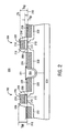
- FIG. 2 is an illustration of a cross-sectional view of a semiconductor substrate having silicide regions formed in accordance with the present invention.
- FIG. 3A is an illustration of a cross-sectional view showing the formation of a isolation region in a semiconductor substrate.
- FIG. 3B is an illustration of a cross-sectional view showing the formation of p type and n type conductivity regions in a semiconductor substrate.
- FIG. 3C is an illustration of a cross-section view showing the formation of a gate dielectric layer, a polysilicon layer, and a sacrificial layer on the substrate of FIG. 3 B.
- FIG. 3D is an illustration of a cross-sectional view showing the formation of an intermediate gate electrode on the substrate of FIG. 3 C.
- FIG. 3E is an illustration of a cross-sectional view showing the formation of sidewall spacers on the substrate of FIG. 3 D.
- FIG. 3F is an illustration of a cross-sectional view showing the formation of recesses and source/drain regions in the substrate of FIG. 3 E.
- FIG. 3G is an illustration of a cross-section view showing the removal of the sacrificial layer from the substrate of FIG. 3 F.
- FIG. 3H is an illustration of a cross-sectional view showing the formation of a metal layer over the substrate of FIG. 3 G.
- FIG. 3I is an illustration of a cross-sectional view showing the formation of silicide regions.
- FIG. 4A is an illustration of a cross-sectional view showing the formation of semiconductor material onto a semiconductor substrate.
- FIG. 4B is an illustration of a cross-sectional view showing the formation of silicide on the substrate of FIG. 4 A.
- the present invention is a novel device structure and method for preventing silicide encroachment in an integrated circuit.
- a sidewall spacer is formed adjacent to an electrode of a device onto which a silicide layer is to be formed.
- the spacer is fabricated so that it has a height which is greater than the combined thickness or height of the electrode plus the silicide layer. In this way the spacer extends above the height of the silicided electrode and prevents silicide from expanding or diffusing from the electrode and causing shorts with adjacent devices or regions.
- isolation regions are used to isolate adjacent devices
- devices are fabricated in such a manner that the isolation region extends above the silicided regions.
- regions which are to receive silicide are etched below the top surface of the isolation region prior to silicide deposition. In this way, silicide is unable to expand or diffuse over the isolation region and cause electrical coupling or shorts between adjacent devices.
- Integrated circuit 200 includes a first metal oxide semiconductor device 202 and a second metal oxide semiconductor device 206 separated by an isolation region 204 .
- Each MOS device includes a gate electrode 208 formed on a gate dielectric layer 210 which is formed on a first surface 212 of a substrate 214 .
- Each gate electrode has a silicide layer 216 formed thereon.
- Semiconductor devices 202 and 206 each also include a pair of sidewall spacers 218 formed adjacent to and along opposite sides of the silicided gate electrodes 220 as shown in FIG. 2 . Sidewall spacers 218 extend a spacer height (T sp ) above substrate surface 212 .
- Spacers 218 have a height (T sp ) which is greater than the height (T sg ) which the silicided gate electrode 220 extends above substrate surface 212 (i.e., T sp >T sg ). That is, spacer height (T sp ) is greater than the sum total of the gate electrode 208 thickness (T g ) and the silicide 216 thickness (T s ) (i.e., T sp >T g +T s ). Spacers 218 preferably extend at least 200 ⁇ above silicided gate electrode 220 . Additionally, in an embodiment of the present invention, silicide layer 216 can be made much thicker, more than two times thicker, than the gate electrode 208 . (i.e., T s >T g ) In this way gate electrode resistance is substantially reduced and poly depletion effects eliminated.
- integrated circuit 200 utilizes planar isolation regions 204 , such as, shallow trench isolation (STI), as shown in FIG. 2.
- a planar isolation region 204 is characterized by the fact that the top surface 221 of isolation region 204 is substantially planar with substrate surface 212 on which gate dielectric layers 210 are formed. That is, the top surface 221 of isolation region 204 extends less than 1500 ⁇ above substrate surface 212 . Shallow trench isolation regions are desirable because they can be formed planar and compact which dramatically improves device packing density.
- planar isolation regions e.g., STI
- source/drain regions 222 are etched or recessed prior to depositing silicide 224 on to the source/drain regions.
- top surface 221 of isolation region 204 extends above the top surface 226 of silicide regions 224 .
- silicide is confined to the source/drain regions and is prevented from diffusing or expanding over the isolation region 204 and causing short circuits between the source/drain regions 224 of adjacent devices 202 and 206 .
- CMOS integrated circuit An example of a method of fabricating an integrated circuit according to methods of the present invention will be described with respect to the fabrication of a CMOS integrated circuit
- the example describes a method of preventing silicide encroachment and thereby preventing shorts between a source/drain region and a gate electrode when forming a silicide on the gate electrode. Additionally the present example illustrates a method of preventing silicide encroachment between source/drain regions of adjacent transistors separated by a planar isolation region.
- the methods described herein can be used independently or integrated together to reduce or eliminate reliability issues associated with silicide encroachment.
- the illustrated method of preventing silicide encroachment on a gate electrode is equally applicable to forming silicide layers on other electrodes such as but not limited to emitter electrodes of bipolar transistors and capacitor electrodes of DRAM cells.
- the illustrated method of preventing silicide encroachment between source/drain regions of adjacent transistors is equally applicable to preventing silicide encroachment over any isolation region separating other device regions such as base and collector contact regions and burried interconnects. The isolation process is especially useful when planar, compact isolation regions are used.
- a substrate 300 such as shown in FIG. 3A, is provided.
- Substrate 300 is generally a semiconductor substrate such as but not limited to a silicon substrate, a gallium arsenide substrate, a silicon germanium substrate, or a silicon on insulator (SOI) substrate. Additionally substrate 300 may or may not include additional epitaxial layers deposited thereon. Still further substrate need not necessarily be semiconductor substrate and can be other types of substrates such as those used for flat panel displays.
- a substrate is defined as a starting material on which devices of the present invention are fabricated.
- an isolation region 302 is formed on substrate 300 .
- isolation region 302 is preferably a planar isolation region such as a shallow trench isolation (STI).
- An STI region 302 can be fabricated by a well known technique such as by blanket depositing a pad oxide layer 304 of about 100 ⁇ onto surface 301 of substrate 300 and a nitride layer 306 of about 1000 ⁇ onto pad oxide layer 304 . Using standard photolithography and etching techniques, an opening can be formed through pad oxide layer 304 and silicon nitride layer 306 at locations where isolation regions are desired. Substrate 300 is then etched to form a trench in substrate 300 with well known techniques.
- a thin (approximately 100-300 ⁇ ) thermal oxide is grown within the trench.
- a fill material such as silicon dioxide deposited by chemical vapor deposition (CVD), is then blanket deposited over silicon nitride layer 306 and into the trench. The fill material can then be polished back with chemical mechanical polishing until the top surface 312 of isolation region 302 is substantially planar with silicon nitride layer 306 as shown in FIG. 3 A.
- Isolation region 302 is said to be a planar isolation region when the top surface 312 of isolation region 302 has a height (T iso ) which is less than 1500 ⁇ above substrate surface 301 . Additionally with the technique described above compact isolation regions having a width of less than 0.4 microns can be fabricated. It is to be appreciated that the use of small and planar isolation regions enables the fabrication of high density integrated circuits. Although STI regions are preferred, other types of planar isolation regions, such as recessed LOCOS and deep trench isolation may be utilized as well as non planar isolation regions, such as LOCOS isolation, if desired.
- a thin, less than 100 ⁇ , gate dielectric layer 318 such as but not limited to silicon dioxide, silicon nitride or silicon oxinitride is formed on surface 301 of substrate 300 .
- a silicon film 320 is then deposited over gate dielectric layer 318 as shown in FIG. 3 C.
- Silicon film 320 is generally polycrystalline silicon but may be other forms of silicon such as amorphous silicon.
- Polysilicon layer 320 can be planarized at this time by chemical-mechanical polishing. In order to reduce polysilicon depletion effects as well as improve photolithography and etch processes, polysilicon layer 320 is formed as thin as possible. However, polysilicon layer 320 must be formed thick enough to prevent channel doping during subsequent source/drain doping.
- a planarized polysilicon layer having a thickness (T g ) of between 100-1500 ⁇ over substrate surface 301 is suitable. (It is to be noted that gate thickness Tg over substrate surface 301 includes the nominal thickness of gate dielectric layer 318 ).
- a sacrificial layer 322 is deposited over polysilicon layer 320 .
- Sacrificial layer 320 can be any suitable material which can be selectively etched with respect to subsequently formed spacers and polysilicon layer 320 .
- Sacrificial layer 320 can be for example, a grown or CVD deposited oxide layer, a fluorine, phosphorous, or boron doped oxide layer, formed by any well known technique.
- sacrificial layer 320 can be a silicon/germanium semiconductor alloy.
- a silicon/germanium semiconductor alloy can be formed by a decomposition of SiH 2 Cl 2 and GeH 4 in H 2 ambient at a temperature between 500-800° C. with 600° C. being preferred.
- the thickness of sacrificial layer 322 sets the upper limit on the amount of silicide that can be subsequently formed on polysilicon layer 320 .
- Sacrificial layer 322 is preferably made thicker than polysilicon layer 320 and ideally at least twice as thick. In this way the electrode can have a silicide layer which is thicker than the polysilicon layer which will allow for the formation of a low resistance electrode.
- sacrificial layer 322 , polysilicon layer 320 and gate dielectric layer 318 are patterned with well known photolithography and etching techniques to form intermediate electrodes 324 .
- tip regions or lightly doped regions can be formed.
- well known photolithography and ion implantation techniques can be used to form n type conductivity tip regions 326 in p type conductivity region 314 and p type conductivity tip regions 328 and n type conductivity region 316 in alignment with the outside edges of intermediate gate electrodes 324 , as shown in FIG. 3 D.
- a pair of sidewall spacers 330 are formed along opposite sides of intermediate gate electrode 324 as shown in FIG. 3 E.
- Sidewall spacers 330 can be formed by any well known method such as by blanket depositing a 100-1000 ⁇ thick conformal layer of silicon nitride over substrate 300 and then anisotropically etching the film to form sidewall spacers 330 .
- Sidewall spacers 330 should be formed of a material which can be selectively etched with respect to sacrificial layer 322 .
- Sidewall spacers 330 need not necessarily be single material spacers and can be composite spacers such as silicon nitride spacers with a thin oxide layer formed adjacent to the intermediate gate electrode 324 .
- Sidewall spacers 330 have a height (T sp ) over substrate surface 301 which is equal to the combined thickness of polysilicon layer 320 (T g ) and sacrificial layer 322 (T sac ).
- substrate 300 can be etched in alignment with sidewall spacers 330 to form recesses 332 as illustrated in FIG. 3 F.
- Recesses 332 are desirable when planar isolation regions 302 are used to isolate source/drain regions of adjacent devices. Recesses 332 can also be used when non planar isolation regions are used in order to provide increased margins for preventing silicide encroachment over the isolation region. Recesses 332 are formed to a depth beneath surface 301 sufficient to keep subsequently formed silicide beneath the top surface of isolation region 302 . Recesses having a depth beneath surface 301 of between 100-1000 ⁇ will generally be sufficient.
- Recesses 332 can be formed by any well known technique such as but not limited to reactive ion etching (RIE) with the chemistry comprising C 2 H 6 and He at a ratio of 2:1. If a suitable spacer material is used, such as silicon nitride, recesses 322 can be formed by over etching into the silicon substrate 300 during the spacer etch.
- RIE reactive ion etching
- sacrificial layer 322 is removed from polysilicon layer 320 . If sacrificial layer 322 is an oxide, it can be removed with a diluted HF solution (50:1 H 2 O to HF). If sacrificial layer 322 is silicon germanium it can be removed with a mixture of NH 4 OH/H 2 O 2 or sulfuric acid (H 2 SO 4 ). Using a silicon germanium sacrificial layer 322 is advantageous because silicon germanium can be removed with an etchant which does not attack oxides which are generally used to fill STI region 302 .
- n type conductivity source/drain regions 331 and p type conductivity source/drain regions 333 can be formed as shown in FIG. 3G.
- N type source/drain regions 331 and p type source/drain regions 333 can be formed by well known photolithography and ion implementation techniques. If polysilicon layer 320 is made as thin as practically possible, (i.e., less than 1000 ⁇ ) the respective source/drain dopings will be able to dope the entire thickness of polysilicon layer 320 , and thereby prevent polysilicon depletion effects.
- low energy (less than 30 Kev) source/drain implant energies can be used to form shallow source/drain junctions, and still ensure complete polysilicon doping. It is to be noted, that if desired deep source/drain regions 331 and 333 can be formed directly after spacer formation in FIG. 3 E. Recesses 332 can then be subsequently etched into the source/drain regions 331 and 333 .
- a silicide layer is formed on polysilicon layer 320 and on source/drain regions 331 and 333 .
- the silicide layers are formed with a self-aligned silicide process or SALICIDE process.
- a metal layer 334 is blanket deposited over substrate 300 as illustrated in FIG. 3 H.
- Metal layer 334 is generally a refractory metal such as but not limited to, titanium, tungsten, nickel, cobalt and palladium which can react with silicon to form a low resistance silicide.
- Metal layer 334 can be deposited by any well known technique such as by sputtering.
- Substrate 300 is now annealed (heated) to cause a chemical reaction between those portions of metal layer 334 which are in direct contact with exposed silicon to form a silicide. That is, silicide is formed wherever silicon is available to react with metal layer 334 such as over source/drain regions 331 and 333 and on polysilicon gate electrode 320 . Since no silicon is available from sidewall spacers 330 or on STI region 302 no silicide forms thereon.
- Substrate 300 is heated to a sufficient temperature and for a sufficient period of time in order to initiate the reaction and produce low resistance silicide.
- Substrate 300 can be thermally cycled with well known techniques such as a rapid thermal anneal or a furnace anneal.
- substrate 300 is subjected to a etchant which selectively removes the unreactive portions of metal layer 334 while leaving silicide 336 on polysilicon layer 320 and on source/drain to regions 331 and 333 .
- metal layer 334 is deposited to a thickness so that after the silicide reaction, spacers 330 extend above the formed silicide 336 and thereby confine the silicide layer between spacers 330 . That is, metal layer 334 is deposited to a thickness so that after silicide formation the spacer height T sp is greater than the sum of a polysilicon gate thickness (T g ) plus the silicide thickness (T s ), (i.e., T sp >T g +T s ).
- metal layer 334 is deposited to a thickness so that after silicide reaction silicide layer 336 on source/drain regions 331 and 333 are beneath the top surface of isolation region 302 . That is, silicide 336 on source/drain regions 331 and 333 has a height less than T iso over substrate surface 301 In this way silicide 336 is confined to the source/drain regions 331 and 333 between spacers 330 and isolation region 302 .
- volume expanding silicides such as nickel silicide
- additional margin should be provided to ensure that the silicide is unable to expand over spacers 330 and/or isolation region 302 .
- the confining techniques of the present invention enable the use of volume expanding silicide layers without worrying about silicide encroachment problems associated with the prior art.
- silicide layer 336 can be selectively deposited onto source/drain regions 331 and 333 and polysilicon layer 320 .
- titanium silicide can be selectively deposited onto source/drain regions 331 and 333 and gate electrode 320 by chemical vapor deposition (CVD) using reactive gasses comprising TiCl 4 , SiH 2 Cl 2 , and/or SiH 4 with a hydrogen carrier gas at a temperature ranging from 600-900° C. and a pressure between 5-100 torr.
- CVD chemical vapor deposition
- Such a process is said to be a selective process because it will form silicide only on exposed silicon surfaces, such as source/drain regions 331 and 332 and polysilicon gate electrode 320 and not on insulative regions such as spacers 330 or STI isolation region 302 . It is recommended to utilize an HF dip prior to selective silicide deposition to ensure complete removal of all native oxide layers formed on silicon surfaces. A subsequent high temperature rapid thermal anneal can be used to convert the as deposited titanium silicide phase (C49) into low resistance phase (C54).
- polysilicon layer 320 can be formed very thin to further decrease poly depletion effects and improve photolithography and etching processes.
- semiconductor material prior to silicide formation.
- a semiconductor material such as silicon germanium
- Ion implementation or insitu doping can be used to dope the semiconductor material to the desired conductivity type and concentration.
- a subsequent anneal step can be used to out diffuse dopants from the semiconductor material to form ultra shallow tip regions as discussed in U.S. patent application Ser. No. 08/363,749, filed Dec. 23, 1994.
- Silicide 336 is then subsequently formed on the deposited semiconductor material 400 as shown in FIG. 4 B.
- the deposited semiconductor material 400 combines with the previously deposited polysilicon layer 320 to set the gate electrode height (T g ).
- sacrificial layer 322 should be made sufficiently thick to compensate for the additional volume occupied by the deposited semiconductor material 400 .
- an advantage of the present method of confining silicide onto an electrode is the fact that it enables thin sidewall spacers (less than 300 ⁇ wide) to be used.
- spacers having a width of at least 2000 ⁇ were required to ensure that they provided a sufficient gap or distance to prevent silicide encroachment.
- the use of thin spacers to confine silicide enables the further scaling of semiconductor devices.
- thin sidewall spacers allow solid source diffusion to be used to form ultra shallow tip regions since dopants have only a short distance (less than 300 ⁇ ) to diffuse underneath the gate electrode. Low resistance ultra shallow tips allow the fabrication of high performance semiconductor devices.
Abstract
A semiconductor device having a novel spacer structure and method of fabrication. The present invention describes a semiconductor device which has an electrode with a first thickness. A silicide layer having a second thickness is formed on the electrode. A sidewall spacer which is formed adjacent to the electrode has a height which is greater than the sum of the thickness of the electrode and the thickness of the silicide layer.
Description
This is a Divisional Application of Ser. No. 09/115,405 filed on Jul. 14, 1998 which is a Divisional Application of Ser. No. 08/884,912 filed on Jun. 30, 1997.
1. Field of the Invention
The present invention relates to the field of semiconductor device fabrication, and more specifically to a method and structure for reducing silicide encroachment in an integrated circuit.
2. Discussion of Related Art
Today integrated circuits are made up of literally millions of active and passive devices such as transistors, capacitors, and resistors. In order to improve device performance, low resistance silicide layers are generally formed on electrodes such as gate electrodes and on doped regions such as source/drain regions.
For example, FIG. 1A is an illustration of a portion of a complementary metal oxide semiconductor (CMOS) integrated circuit. Integrated circuit 100 includes a PMOS transistor 102 and an NMOS transistor 104 separated by an isolation region 103. NMOS and PMOS transistor 102 and 104 each include a pair of source/drain regions 106, a polysilicon gate electrode 107, and a gate dielectric layer 101. Insulative sidewall spacers 108 are formed along opposite sidewalls of gate electrode 107 as shown in FIG. 1A. In order to decrease the resistance of gate electrode 107 and source/drain regions 106, low resistance silicide is formed on gate electrode 107 and source/drain regions 106.
One method of forming a low resistance silicide is a self-aligned silicide process known as a SALICIDE process. In such a process, a refractory metal layer 109, such as titanium, tungsten, cobalt, nickel or palladium, is blanket deposited over the substrate and MOS devices 102 and 104 as shown in FIG. 1B. The substrate is then heated to cause a reaction between metal layer 109 and exposed silicon surfaces such as source/drain regions 106 and gate electrode 107 to form a low resistance silicide 110 as shown in FIG. 1C. Locations where no silicon is available for reaction, such as oxide spacers 108 and isolation region 103, metal layer 109 remains unreacted. Unreacted metal 109 can then be etched away leaving silicide only on source/drain regions 106 and on gate electrode 107 as shown in FIG. 1D.
A problem with the above described process is that circuits fabricated with the process are vulnerable to short circuits due to silicide encroachment. That is, during the high temperature anneal used to form silicide layer 110 or during subsequent anneal steps, silicide can diffuse or spill over from polysilicon gate electrode 107 and source/drain regions 106 and form an undesired silicide bridge 112 over sidewall spacers 108 and cause shorting of gate electrode 107 to source/drain region 106. Silicide encroachment is further compounded by silicides, such as nickel silicide (NiSi), which experience silicide volume increases over the combined volume of the consumed silicon and metal layer. For example, the reaction of nickel and silicon creates a nickel silicide/polysilicon gate electrode layer having an approximately 18% volume increase over the silicon electrode shown in FIG. 1A. As such is shown in FIG. 1C to silicide 110 reaches above spacer 108.
Silicide encroachment can also cause short circuits between source/drain regions of adjacent devices which are separated by planar isolation regions. For example, as also shown in FIG. 1E, as isolation regions are made more planar and made more compact (less than 0.4 microns wide), such as with shallow trench isolation (STI), silicide from adjacent transistor source/drain regions 106 can diffuse or spill over isolation region 103 and cause silicide shorts 114 between adjacent devices.
In order to help reduce the potential for silicide shorts between source/drain regions and gate electrodes, polysilicon layer 107 is formed thick, (i.e., greater than 2000 Å), in order to ensure that silicide 110 has a large distance to bridge over spacers 108. Unfortunately, however, by increasing the thickness of polysilicon gate 107, the ion implantation technique used to dope gate electrode 107 (typically the source/drain implantation) is unable to drive dopants sufficiently deep into the electrode 107 to provide a uniformly doped low conductivity gate electrode. When the lower portion (portion near gate dielectric layer 101) of the gate electrode has no or reduced doping, the device has increased gate resistance which detrimentally affects the drive current. This non uniform gate electrode doping is commonly referred to as “polysilicon depletion effects”.
Additionally, in order to prevent silicide encroachment, silicide layer 110 is generally kept thin (i.e., thinner than the thickness of the polysilicon gate electrode). It would be desirable to be able to form silicide layers which are thicker than the polysilicon layer so that lower resistance electrodes can be fabricated and device performance improved.
Thus, what is desired is a device structure and method of fabrication which reduces silicide encroachment as well as poly depletion effects.
In a first embodiment of the present invention, a semiconductor device having a novel spacer structure and its method of fabrication is described. According to the first embodiment a semiconductor device having an electrode with a first thickness is formed. A silicide layer having a second thickness is formed on the electrode. A sidewall spacer formed adjacent to the electrode and has a height which is greater than the sum of the thickness of the electrode and the thickness of the silicide layer. In another embodiment of the present invention, regions of a device which are to receive silicide are etched below the top surface of isolation regions prior to silicide deposition. In this way silicide regions are formed below the top surface of the isolation regions.
FIG. 1A is an illustration of a cross-sectional view of a conventional CMOS integrated circuit.
FIG. 1B is an illustration of a cross-sectional view showing the formation of a metal layer over the substrate at FIG. 1A.
FIG. 1C is an illustration of a cross-sectional view showing the formation of a silicide layer from the metal layer on the substrate at FIG. 1B.
FIG. 1D is an illustration of a cross-sectional view showing the removal of unreacted metal from the substrate of FIG. 1C.
FIG. 1E is an illustration of a cross-sectional view showing silicide encroachment on the substrate of FIG. 1D.
FIG. 2 is an illustration of a cross-sectional view of a semiconductor substrate having silicide regions formed in accordance with the present invention.
FIG. 3A is an illustration of a cross-sectional view showing the formation of a isolation region in a semiconductor substrate.
FIG. 3B is an illustration of a cross-sectional view showing the formation of p type and n type conductivity regions in a semiconductor substrate.
FIG. 3C is an illustration of a cross-section view showing the formation of a gate dielectric layer, a polysilicon layer, and a sacrificial layer on the substrate of FIG. 3B.
FIG. 3D is an illustration of a cross-sectional view showing the formation of an intermediate gate electrode on the substrate of FIG. 3C.
FIG. 3E is an illustration of a cross-sectional view showing the formation of sidewall spacers on the substrate of FIG. 3D.
FIG. 3F is an illustration of a cross-sectional view showing the formation of recesses and source/drain regions in the substrate of FIG. 3E.
FIG. 3G is an illustration of a cross-section view showing the removal of the sacrificial layer from the substrate of FIG. 3F.
FIG. 3H is an illustration of a cross-sectional view showing the formation of a metal layer over the substrate of FIG. 3G.
FIG. 3I is an illustration of a cross-sectional view showing the formation of silicide regions.
FIG. 4A is an illustration of a cross-sectional view showing the formation of semiconductor material onto a semiconductor substrate.
FIG. 4B is an illustration of a cross-sectional view showing the formation of silicide on the substrate of FIG. 4A.
A novel device structure and method for preventing silicide encroachment is described. In the following description numerous specific details are set forth such as specific materials and processes in order to provide a thorough understanding of the present invention. In other instances well known semiconductor processing techniques and machinery have not been set forth in detail in order to not unnecessarily obscure the present invention.
The present invention is a novel device structure and method for preventing silicide encroachment in an integrated circuit. In one embodiment of the present invention a sidewall spacer is formed adjacent to an electrode of a device onto which a silicide layer is to be formed. The spacer is fabricated so that it has a height which is greater than the combined thickness or height of the electrode plus the silicide layer. In this way the spacer extends above the height of the silicided electrode and prevents silicide from expanding or diffusing from the electrode and causing shorts with adjacent devices or regions.
In another embodiment of the present invention where isolation regions are used to isolate adjacent devices, devices are fabricated in such a manner that the isolation region extends above the silicided regions. According to this embodiment of the present invention, regions which are to receive silicide are etched below the top surface of the isolation region prior to silicide deposition. In this way, silicide is unable to expand or diffuse over the isolation region and cause electrical coupling or shorts between adjacent devices.
An example of an integrated circuit 200 which incorporates the structures and methods of the present invention is illustrated in FIG. 2. Integrated circuit 200 includes a first metal oxide semiconductor device 202 and a second metal oxide semiconductor device 206 separated by an isolation region 204. Each MOS device includes a gate electrode 208 formed on a gate dielectric layer 210 which is formed on a first surface 212 of a substrate 214. Each gate electrode has a silicide layer 216 formed thereon. Semiconductor devices 202 and 206 each also include a pair of sidewall spacers 218 formed adjacent to and along opposite sides of the silicided gate electrodes 220 as shown in FIG. 2. Sidewall spacers 218 extend a spacer height (Tsp) above substrate surface 212. Spacers 218 have a height (Tsp) which is greater than the height (Tsg) which the silicided gate electrode 220 extends above substrate surface 212 (i.e., Tsp>Tsg). That is, spacer height (Tsp) is greater than the sum total of the gate electrode 208 thickness (Tg) and the silicide 216 thickness (Ts) (i.e., Tsp>Tg+Ts). Spacers 218 preferably extend at least 200 Å above silicided gate electrode 220. Additionally, in an embodiment of the present invention, silicide layer 216 can be made much thicker, more than two times thicker, than the gate electrode 208. (i.e., Ts>Tg) In this way gate electrode resistance is substantially reduced and poly depletion effects eliminated.
In another embodiment of the present invention, integrated circuit 200 utilizes planar isolation regions 204, such as, shallow trench isolation (STI), as shown in FIG. 2. A planar isolation region 204 is characterized by the fact that the top surface 221 of isolation region 204 is substantially planar with substrate surface 212 on which gate dielectric layers 210 are formed. That is, the top surface 221 of isolation region 204 extends less than 1500 Å above substrate surface 212. Shallow trench isolation regions are desirable because they can be formed planar and compact which dramatically improves device packing density. In the embodiment of the present invention where planar isolation regions (e.g., STI) are utilized, source/drain regions 222 are etched or recessed prior to depositing silicide 224 on to the source/drain regions. In this way, the top surface 221 of isolation region 204 extends above the top surface 226 of silicide regions 224. In this way silicide is confined to the source/drain regions and is prevented from diffusing or expanding over the isolation region 204 and causing short circuits between the source/drain regions 224 of adjacent devices 202 and 206.
An example of a method of fabricating an integrated circuit according to methods of the present invention will be described with respect to the fabrication of a CMOS integrated circuit The example describes a method of preventing silicide encroachment and thereby preventing shorts between a source/drain region and a gate electrode when forming a silicide on the gate electrode. Additionally the present example illustrates a method of preventing silicide encroachment between source/drain regions of adjacent transistors separated by a planar isolation region. The methods described herein can be used independently or integrated together to reduce or eliminate reliability issues associated with silicide encroachment. It is to be appreciated that the illustrated method of preventing silicide encroachment on a gate electrode is equally applicable to forming silicide layers on other electrodes such as but not limited to emitter electrodes of bipolar transistors and capacitor electrodes of DRAM cells. Similarly the illustrated method of preventing silicide encroachment between source/drain regions of adjacent transistors is equally applicable to preventing silicide encroachment over any isolation region separating other device regions such as base and collector contact regions and burried interconnects. The isolation process is especially useful when planar, compact isolation regions are used.
According to the present invention a substrate 300, such as shown in FIG. 3A, is provided. Substrate 300 is generally a semiconductor substrate such as but not limited to a silicon substrate, a gallium arsenide substrate, a silicon germanium substrate, or a silicon on insulator (SOI) substrate. Additionally substrate 300 may or may not include additional epitaxial layers deposited thereon. Still further substrate need not necessarily be semiconductor substrate and can be other types of substrates such as those used for flat panel displays. For the purposes of the present invention a substrate is defined as a starting material on which devices of the present invention are fabricated.
According to an embodiment of the present invention, an isolation region 302 is formed on substrate 300. In order to fabricate high density integrated circuits, isolation region 302 is preferably a planar isolation region such as a shallow trench isolation (STI). An STI region 302 can be fabricated by a well known technique such as by blanket depositing a pad oxide layer 304 of about 100 Å onto surface 301 of substrate 300 and a nitride layer 306 of about 1000 Å onto pad oxide layer 304. Using standard photolithography and etching techniques, an opening can be formed through pad oxide layer 304 and silicon nitride layer 306 at locations where isolation regions are desired. Substrate 300 is then etched to form a trench in substrate 300 with well known techniques. Next, a thin (approximately 100-300 Å) thermal oxide is grown within the trench. A fill material, such as silicon dioxide deposited by chemical vapor deposition (CVD), is then blanket deposited over silicon nitride layer 306 and into the trench. The fill material can then be polished back with chemical mechanical polishing until the top surface 312 of isolation region 302 is substantially planar with silicon nitride layer 306 as shown in FIG. 3A.
Next, as shown in FIG. 3B, silicon nitride layer 306 and pad oxide layer 304 are removed with well known techniques to form a shallow and compact isolation region 302. Isolation region 302 is said to be a planar isolation region when the top surface 312 of isolation region 302 has a height (Tiso) which is less than 1500 Å above substrate surface 301. Additionally with the technique described above compact isolation regions having a width of less than 0.4 microns can be fabricated. It is to be appreciated that the use of small and planar isolation regions enables the fabrication of high density integrated circuits. Although STI regions are preferred, other types of planar isolation regions, such as recessed LOCOS and deep trench isolation may be utilized as well as non planar isolation regions, such as LOCOS isolation, if desired.
Next, as also shown in FIG. 3B, well known masking and ion implementation techniques are used to form a p type region 314 and an n type region 316 in substrate 300.
Next, as illustrated in FIG. 3C, a thin, less than 100 Å, gate dielectric layer 318 such as but not limited to silicon dioxide, silicon nitride or silicon oxinitride is formed on surface 301 of substrate 300. A silicon film 320 is then deposited over gate dielectric layer 318 as shown in FIG. 3C. Silicon film 320 is generally polycrystalline silicon but may be other forms of silicon such as amorphous silicon. Polysilicon layer 320 can be planarized at this time by chemical-mechanical polishing. In order to reduce polysilicon depletion effects as well as improve photolithography and etch processes, polysilicon layer 320 is formed as thin as possible. However, polysilicon layer 320 must be formed thick enough to prevent channel doping during subsequent source/drain doping. A planarized polysilicon layer having a thickness (Tg) of between 100-1500 Å over substrate surface 301 is suitable. (It is to be noted that gate thickness Tg over substrate surface 301 includes the nominal thickness of gate dielectric layer 318).
Next, as also shown in FIG. 3C, a sacrificial layer 322 is deposited over polysilicon layer 320. Sacrificial layer 320 can be any suitable material which can be selectively etched with respect to subsequently formed spacers and polysilicon layer 320. Sacrificial layer 320 can be for example, a grown or CVD deposited oxide layer, a fluorine, phosphorous, or boron doped oxide layer, formed by any well known technique. Additionally sacrificial layer 320 can be a silicon/germanium semiconductor alloy. A silicon/germanium semiconductor alloy can be formed by a decomposition of SiH2Cl2 and GeH4 in H2 ambient at a temperature between 500-800° C. with 600° C. being preferred. It is to be appreciated that the thickness of sacrificial layer 322 sets the upper limit on the amount of silicide that can be subsequently formed on polysilicon layer 320. Sacrificial layer 322 is preferably made thicker than polysilicon layer 320 and ideally at least twice as thick. In this way the electrode can have a silicide layer which is thicker than the polysilicon layer which will allow for the formation of a low resistance electrode.
Next, as shown in FIG. 3D, sacrificial layer 322, polysilicon layer 320 and gate dielectric layer 318 are patterned with well known photolithography and etching techniques to form intermediate electrodes 324. At this time if desired, tip regions or lightly doped regions can be formed. For example, well known photolithography and ion implantation techniques can be used to form n type conductivity tip regions 326 in p type conductivity region 314 and p type conductivity tip regions 328 and n type conductivity region 316 in alignment with the outside edges of intermediate gate electrodes 324, as shown in FIG. 3D.
Next, a pair of sidewall spacers 330 are formed along opposite sides of intermediate gate electrode 324 as shown in FIG. 3E. Sidewall spacers 330 can be formed by any well known method such as by blanket depositing a 100-1000 Å thick conformal layer of silicon nitride over substrate 300 and then anisotropically etching the film to form sidewall spacers 330. Sidewall spacers 330 should be formed of a material which can be selectively etched with respect to sacrificial layer 322. Sidewall spacers 330 need not necessarily be single material spacers and can be composite spacers such as silicon nitride spacers with a thin oxide layer formed adjacent to the intermediate gate electrode 324. Sidewall spacers 330 have a height (Tsp) over substrate surface 301 which is equal to the combined thickness of polysilicon layer 320 (Tg) and sacrificial layer 322 (Tsac).
Next, if desired, substrate 300 can be etched in alignment with sidewall spacers 330 to form recesses 332 as illustrated in FIG. 3F. Recesses 332 are desirable when planar isolation regions 302 are used to isolate source/drain regions of adjacent devices. Recesses 332 can also be used when non planar isolation regions are used in order to provide increased margins for preventing silicide encroachment over the isolation region. Recesses 332 are formed to a depth beneath surface 301 sufficient to keep subsequently formed silicide beneath the top surface of isolation region 302. Recesses having a depth beneath surface 301 of between 100-1000 Å will generally be sufficient. Recesses 332 can be formed by any well known technique such as but not limited to reactive ion etching (RIE) with the chemistry comprising C2H6 and He at a ratio of 2:1. If a suitable spacer material is used, such as silicon nitride, recesses 322 can be formed by over etching into the silicon substrate 300 during the spacer etch.
Next, as illustrated in FIG. 3G, sacrificial layer 322 is removed from polysilicon layer 320. If sacrificial layer 322 is an oxide, it can be removed with a diluted HF solution (50:1 H2O to HF). If sacrificial layer 322 is silicon germanium it can be removed with a mixture of NH4OH/H2O2 or sulfuric acid (H2SO4). Using a silicon germanium sacrificial layer 322 is advantageous because silicon germanium can be removed with an etchant which does not attack oxides which are generally used to fill STI region 302.
After sacrificial layer 322 has been removed, n type conductivity source/drain regions 331 and p type conductivity source/drain regions 333 can be formed as shown in FIG. 3G. N type source/drain regions 331 and p type source/drain regions 333 can be formed by well known photolithography and ion implementation techniques. If polysilicon layer 320 is made as thin as practically possible, (i.e., less than 1000 Å) the respective source/drain dopings will be able to dope the entire thickness of polysilicon layer 320, and thereby prevent polysilicon depletion effects. Additionally, by having a thin polysilicon layer, low energy (less than 30 Kev) source/drain implant energies can be used to form shallow source/drain junctions, and still ensure complete polysilicon doping. It is to be noted, that if desired deep source/ drain regions 331 and 333 can be formed directly after spacer formation in FIG. 3E. Recesses 332 can then be subsequently etched into the source/ drain regions 331 and 333.
Next, a silicide layer is formed on polysilicon layer 320 and on source/ drain regions 331 and 333. In one embodiment of the present invention the silicide layers are formed with a self-aligned silicide process or SALICIDE process. In a salicide process, a metal layer 334 is blanket deposited over substrate 300 as illustrated in FIG. 3H. Metal layer 334 is generally a refractory metal such as but not limited to, titanium, tungsten, nickel, cobalt and palladium which can react with silicon to form a low resistance silicide. Metal layer 334 can be deposited by any well known technique such as by sputtering.
It is to be appreciated that for preventing silicide encroachment on gate electrode 320, metal layer 334 is deposited to a thickness so that after the silicide reaction, spacers 330 extend above the formed silicide 336 and thereby confine the silicide layer between spacers 330. That is, metal layer 334 is deposited to a thickness so that after silicide formation the spacer height Tsp is greater than the sum of a polysilicon gate thickness (Tg) plus the silicide thickness (Ts), (i.e., Tsp>Tg+Ts). Similarly, for preventing silicide encroachment over isolation region 302, metal layer 334 is deposited to a thickness so that after silicide reaction silicide layer 336 on source/ drain regions 331 and 333 are beneath the top surface of isolation region 302. That is, silicide 336 on source/ drain regions 331 and 333 has a height less than Tiso over substrate surface 301 In this way silicide 336 is confined to the source/ drain regions 331 and 333 between spacers 330 and isolation region 302.
It is to be appreciated that when volume expanding silicides are utilized, such as nickel silicide, additional margin should be provided to ensure that the silicide is unable to expand over spacers 330 and/or isolation region 302. The confining techniques of the present invention enable the use of volume expanding silicide layers without worrying about silicide encroachment problems associated with the prior art.
In an alternative to forming silicide 336 by a self-aligned process, silicide layer 336 can be selectively deposited onto source/ drain regions 331 and 333 and polysilicon layer 320. For example, titanium silicide can be selectively deposited onto source/ drain regions 331 and 333 and gate electrode 320 by chemical vapor deposition (CVD) using reactive gasses comprising TiCl4, SiH2Cl2, and/or SiH4 with a hydrogen carrier gas at a temperature ranging from 600-900° C. and a pressure between 5-100 torr. Such a process is said to be a selective process because it will form silicide only on exposed silicon surfaces, such as source/ drain regions 331 and 332 and polysilicon gate electrode 320 and not on insulative regions such as spacers 330 or STI isolation region 302. It is recommended to utilize an HF dip prior to selective silicide deposition to ensure complete removal of all native oxide layers formed on silicon surfaces. A subsequent high temperature rapid thermal anneal can be used to convert the as deposited titanium silicide phase (C49) into low resistance phase (C54).
In a selective deposition process, insignificant amounts of silicon are consumed during the deposition as compared to a salicide process. Since less silicon is needed to support the silicide deposition, when a selective silicide process is used polysilicon layer 320 can be formed very thin to further decrease poly depletion effects and improve photolithography and etching processes.
It is to be appreciated that it may be desirable to selectively deposit semiconductor material prior to silicide formation. For example, after forming sidewall spacers 330 and recesses 332, and removing sacrificial layer 322 it may be desirable to selectively deposit a semiconductor material, such as silicon germanium, into recesses 332 and onto polysilicon layer 320 as shown in FIG. 4A. Ion implementation or insitu doping, can be used to dope the semiconductor material to the desired conductivity type and concentration. Additionally, a subsequent anneal step can be used to out diffuse dopants from the semiconductor material to form ultra shallow tip regions as discussed in U.S. patent application Ser. No. 08/363,749, filed Dec. 23, 1994. Additionally depositing additional semiconductor material on source/drain regions enables the manufacture of “raised” source/drain regions which reduce resistances of the device and improves performance. Silicide 336 is then subsequently formed on the deposited semiconductor material 400 as shown in FIG. 4B. In such a case, the deposited semiconductor material 400 combines with the previously deposited polysilicon layer 320 to set the gate electrode height (Tg). In such a case, sacrificial layer 322 should be made sufficiently thick to compensate for the additional volume occupied by the deposited semiconductor material 400.
It is to be appreciated that an advantage of the present method of confining silicide onto an electrode is the fact that it enables thin sidewall spacers (less than 300 Å wide) to be used. In prior art processes, spacers having a width of at least 2000 Å were required to ensure that they provided a sufficient gap or distance to prevent silicide encroachment. The use of thin spacers to confine silicide enables the further scaling of semiconductor devices. Additionally thin sidewall spacers allow solid source diffusion to be used to form ultra shallow tip regions since dopants have only a short distance (less than 300 Å) to diffuse underneath the gate electrode. Low resistance ultra shallow tips allow the fabrication of high performance semiconductor devices.
Thus, device structures and methods for preventing silicide encroachment have been described.
Claims (5)
1. A semiconductor device comprising:
a gate electrode formed on a gate dielectric formed on a substrate surface, the gate electrode having a first thickness;
a gate silicon germanium film formed on the gate electrode, the gate silicon germanium film having a second thickness;
a gate silicide layer formed on the gate silicon germanium film, the gate silicide layer having a third thickness;
a pair of sidewall spacers on opposite sides of the gate electrode, the sidewall spacers having a height of at least 200 Å above the third thickness of the gate silicide layer and a width of less than 300 Å;
a pair of source and drain regions formed on opposite sides of said gate electrode, said source and drain regions having a silicon germanium film formed beneath said substrate surface and a pair of ultra shallow tip regions formed beneath the pair of sidewall spacers.
2. The semiconductor device of claim 1 , wherein the gate electrode is polysilicon.
3. The semiconductor device of claim 1 further comprising:
a silicide layer formed on the silicon germanium film of said source and drain regions.
4. The semiconductor device of claim 3 further comprising:
an isolation region having a top surface positioned below the top surface of the silicon germanium film of said source and drain regions.
5. The semiconductor device of claim 3 further comprising: an isolation region having a top surface positioned below the silicide layer.
Priority Applications (2)
| Application Number | Priority Date | Filing Date | Title |
|---|---|---|---|
| US09/654,315 US6777759B1 (en) | 1997-06-30 | 2000-09-01 | Device structure and method for reducing silicide encroachment |
| US10/010,525 US20020053711A1 (en) | 1997-06-30 | 2001-12-07 | Device structure and method for reducing silicide encroachment |
Applications Claiming Priority (3)
| Application Number | Priority Date | Filing Date | Title |
|---|---|---|---|
| US08/884,912 US6518155B1 (en) | 1997-06-30 | 1997-06-30 | Device structure and method for reducing silicide encroachment |
| US09/115,405 US6765273B1 (en) | 1997-06-30 | 1998-07-14 | Device structure and method for reducing silicide encroachment |
| US09/654,315 US6777759B1 (en) | 1997-06-30 | 2000-09-01 | Device structure and method for reducing silicide encroachment |
Related Parent Applications (1)
| Application Number | Title | Priority Date | Filing Date |
|---|---|---|---|
| US09/115,405 Division US6765273B1 (en) | 1997-06-30 | 1998-07-14 | Device structure and method for reducing silicide encroachment |
Related Child Applications (1)
| Application Number | Title | Priority Date | Filing Date |
|---|---|---|---|
| US10/010,525 Division US20020053711A1 (en) | 1997-06-30 | 2001-12-07 | Device structure and method for reducing silicide encroachment |
Publications (1)
| Publication Number | Publication Date |
|---|---|
| US6777759B1 true US6777759B1 (en) | 2004-08-17 |
Family
ID=32852912
Family Applications (2)
| Application Number | Title | Priority Date | Filing Date |
|---|---|---|---|
| US09/654,315 Expired - Lifetime US6777759B1 (en) | 1997-06-30 | 2000-09-01 | Device structure and method for reducing silicide encroachment |
| US10/010,525 Abandoned US20020053711A1 (en) | 1997-06-30 | 2001-12-07 | Device structure and method for reducing silicide encroachment |
Family Applications After (1)
| Application Number | Title | Priority Date | Filing Date |
|---|---|---|---|
| US10/010,525 Abandoned US20020053711A1 (en) | 1997-06-30 | 2001-12-07 | Device structure and method for reducing silicide encroachment |
Country Status (1)
| Country | Link |
|---|---|
| US (2) | US6777759B1 (en) |
Cited By (28)
| Publication number | Priority date | Publication date | Assignee | Title |
|---|---|---|---|---|
| US20040178476A1 (en) * | 2002-09-30 | 2004-09-16 | Brask Justin K. | Etching metal using sonication |
| US20040227185A1 (en) * | 2003-01-15 | 2004-11-18 | Renesas Technology Corp. | Semiconductor device |
| US20040266102A1 (en) * | 2003-06-25 | 2004-12-30 | Il-Young Kwon | Method for manufacturing capacitor bottom electrode of semiconductor device |
| US20050067665A1 (en) * | 2003-09-19 | 2005-03-31 | Satoshi Matsuda | Semiconductor device including field-effect transistor using salicide (self-aligned silicide) structure and method of fabricating the same |
| US20050087803A1 (en) * | 2002-01-09 | 2005-04-28 | Matsushita Electric Industrial Co., Ltd. | Semiconductor device and method for fabricating the same |
| US20050090082A1 (en) * | 2003-10-28 | 2005-04-28 | Texas Instruments Incorporated | Method and system for improving performance of MOSFETs |
| US20050133832A1 (en) * | 2003-12-22 | 2005-06-23 | Anand Murthy | Methods for selective deposition to improve selectivity |
| US20050156154A1 (en) * | 2004-01-16 | 2005-07-21 | International Business Machines Corporation | Protecting Silicon Germanium Sidewall with Silicon for Strained Silicon/Silicon Germanium MOSFETs |
| US20060145270A1 (en) * | 2004-12-30 | 2006-07-06 | Dongbuanam Semiconductor Inc. | Semiconductor device having silicide-blocking layer and fabrication method thereof |
| US20060228844A1 (en) * | 2005-03-30 | 2006-10-12 | Marcus Culmsee | Integration scheme for fully silicided gate |
| US20060252191A1 (en) * | 2005-05-03 | 2006-11-09 | Advanced Micro Devices, Inc. | Methodology for deposition of doped SEG for raised source/drain regions |
| US20060281271A1 (en) * | 2005-06-13 | 2006-12-14 | Advanced Micro Devices, Inc. | Method of forming a semiconductor device having an epitaxial layer and device thereof |
| US20070068627A1 (en) * | 2004-09-17 | 2007-03-29 | International Business Machines Corporation | Electrical Open/Short Contact Alignment Structure for Active Region vs. Gate Region |
| US20070122955A1 (en) * | 2005-11-29 | 2007-05-31 | International Business Machines Corporation | Method of manufacturing a semiconductor structure |
| US7241700B1 (en) | 2004-10-20 | 2007-07-10 | Advanced Micro Devices, Inc. | Methods for post offset spacer clean for improved selective epitaxy silicon growth |
| US20080038893A1 (en) * | 2002-08-29 | 2008-02-14 | Warner Juengling | Reverse metal process for creating a metal silicide transistor gate structure |
| US20080050863A1 (en) * | 2006-08-28 | 2008-02-28 | International Business Machines Corporation | Semiconductor structure including multiple stressed layers |
| US20080157091A1 (en) * | 2004-06-17 | 2008-07-03 | Samsung Electronics Co., Ltd. | Methods of fabricating a semiconductor device using a cyclic selective epitaxial growth technique and semiconductor devices formed using the same |
| US20080171414A1 (en) * | 2007-01-11 | 2008-07-17 | Samsung Electronics Co., Ltd. | Method of fabricating semiconductor devices having a gate silicide |
| US7402485B1 (en) | 2004-10-20 | 2008-07-22 | Advanced Micro Devices, Inc. | Method of forming a semiconductor device |
| US7402207B1 (en) | 2004-05-05 | 2008-07-22 | Advanced Micro Devices, Inc. | Method and apparatus for controlling the thickness of a selective epitaxial growth layer |
| US20080179689A1 (en) * | 2007-01-31 | 2008-07-31 | Taiwan Semiconductor Manufacturing Company, Ltd. | Metal salicide formation having nitride liner to reduce silicide stringer and encroachment |
| US7456062B1 (en) | 2004-10-20 | 2008-11-25 | Advanced Micro Devices, Inc. | Method of forming a semiconductor device |
| US7553732B1 (en) | 2005-06-13 | 2009-06-30 | Advanced Micro Devices, Inc. | Integration scheme for constrained SEG growth on poly during raised S/D processing |
| US7572705B1 (en) | 2005-09-21 | 2009-08-11 | Advanced Micro Devices, Inc. | Semiconductor device and method of manufacturing a semiconductor device |
| US20100301394A1 (en) * | 2004-12-28 | 2010-12-02 | Fujitsu Semiconductor Limited | Semiconductor device and fabrication method thereof |
| US8703592B2 (en) | 2010-03-19 | 2014-04-22 | Samsung Electronics Co., Ltd. | Methods of forming semiconductor devices having faceted semiconductor patterns |
| US10312096B2 (en) * | 2016-12-12 | 2019-06-04 | Applied Materials, Inc. | Methods for titanium silicide formation using TiCl4 precursor and silicon-containing precursor |
Families Citing this family (35)
| Publication number | Priority date | Publication date | Assignee | Title |
|---|---|---|---|---|
| US6828630B2 (en) | 2003-01-07 | 2004-12-07 | International Business Machines Corporation | CMOS device on ultrathin SOI with a deposited raised source/drain, and a method of manufacture |
| US7019351B2 (en) | 2003-03-12 | 2006-03-28 | Micron Technology, Inc. | Transistor devices, and methods of forming transistor devices and circuit devices |
| US6987056B2 (en) * | 2003-07-08 | 2006-01-17 | Hynix Semiconductor Inc. | Method of forming gates in semiconductor devices |
| US7183182B2 (en) * | 2003-09-24 | 2007-02-27 | International Business Machines Corporation | Method and apparatus for fabricating CMOS field effect transistors |
| US20050156208A1 (en) * | 2003-09-30 | 2005-07-21 | Taiwan Semiconductor Manufacturing Company, Ltd. | Device having multiple silicide types and a method for its fabrication |
| JP2005116970A (en) * | 2003-10-10 | 2005-04-28 | Toshiba Corp | Non-volatile semiconductor memory |
| KR100558007B1 (en) * | 2003-11-24 | 2006-03-06 | 삼성전자주식회사 | transistor and method of fabricating the same |
| US7033869B1 (en) * | 2004-01-13 | 2006-04-25 | Advanced Micro Devices | Strained silicon semiconductor on insulator MOSFET |
| US6921691B1 (en) * | 2004-03-18 | 2005-07-26 | Infineon Technologies Ag | Transistor with dopant-bearing metal in source and drain |
| US8006071B2 (en) | 2004-03-31 | 2011-08-23 | Altera Corporation | Processors operable to allow flexible instruction alignment |
| US20050253205A1 (en) * | 2004-05-17 | 2005-11-17 | Fujitsu Limited | Semiconductor device and method for fabricating the same |
| US7498641B2 (en) * | 2004-05-28 | 2009-03-03 | Taiwan Semiconductor Manufacturing Company, Ltd. | Partial replacement silicide gate |
| US8178902B2 (en) * | 2004-06-17 | 2012-05-15 | Infineon Technologies Ag | CMOS transistor with dual high-k gate dielectric and method of manufacture thereof |
| US8399934B2 (en) * | 2004-12-20 | 2013-03-19 | Infineon Technologies Ag | Transistor device |
| US7592678B2 (en) * | 2004-06-17 | 2009-09-22 | Infineon Technologies Ag | CMOS transistors with dual high-k gate dielectric and methods of manufacture thereof |
| US7413957B2 (en) * | 2004-06-24 | 2008-08-19 | Applied Materials, Inc. | Methods for forming a transistor |
| US7344934B2 (en) | 2004-12-06 | 2008-03-18 | Infineon Technologies Ag | CMOS transistor and method of manufacture thereof |
| US7160781B2 (en) * | 2005-03-21 | 2007-01-09 | Infineon Technologies Ag | Transistor device and methods of manufacture thereof |
| US7361538B2 (en) * | 2005-04-14 | 2008-04-22 | Infineon Technologies Ag | Transistors and methods of manufacture thereof |
| US20070052037A1 (en) * | 2005-09-02 | 2007-03-08 | Hongfa Luan | Semiconductor devices and methods of manufacture thereof |
| US20070052036A1 (en) * | 2005-09-02 | 2007-03-08 | Hongfa Luan | Transistors and methods of manufacture thereof |
| US8188551B2 (en) | 2005-09-30 | 2012-05-29 | Infineon Technologies Ag | Semiconductor devices and methods of manufacture thereof |
| US7462538B2 (en) * | 2005-11-15 | 2008-12-09 | Infineon Technologies Ag | Methods of manufacturing multiple gate CMOS transistors having different gate dielectric materials |
| US7495290B2 (en) * | 2005-12-14 | 2009-02-24 | Infineon Technologies Ag | Semiconductor devices and methods of manufacture thereof |
| US7510943B2 (en) * | 2005-12-16 | 2009-03-31 | Infineon Technologies Ag | Semiconductor devices and methods of manufacture thereof |
| US20080050898A1 (en) * | 2006-08-23 | 2008-02-28 | Hongfa Luan | Semiconductor devices and methods of manufacture thereof |
| US7838375B1 (en) * | 2007-05-25 | 2010-11-23 | National Semiconductor Corporation | System and method for providing a polyemit module for a self aligned heterojunction bipolar transistor architecture |
| JP5104373B2 (en) * | 2008-02-14 | 2012-12-19 | 日本ゼオン株式会社 | Production method of retardation plate |
| DE102008054075B4 (en) * | 2008-10-31 | 2010-09-23 | Advanced Micro Devices, Inc., Sunnyvale | Semiconductor device having a lowered drain and source region in conjunction with a method of complex silicide fabrication in transistors |
| WO2010049086A2 (en) * | 2008-10-31 | 2010-05-06 | Advanced Micro Devices, Inc. | Recessed drain and source areas in combination with advanced silicide formation in transistors |
| KR20100090091A (en) * | 2009-02-05 | 2010-08-13 | 삼성전자주식회사 | Method of fabricating a semiconductor device having a metal-semiconductor compound region |
| US20110108912A1 (en) * | 2009-11-09 | 2011-05-12 | Hamilton Lu | Methods for fabricating trench metal oxide semiconductor field effect transistors |
| KR20110100738A (en) * | 2010-03-05 | 2011-09-15 | 삼성전자주식회사 | Semiconductor memory device and method for manufacturing the same |
| US8754472B2 (en) | 2011-03-10 | 2014-06-17 | O2Micro, Inc. | Methods for fabricating transistors including one or more circular trenches |
| US9337190B2 (en) | 2013-03-12 | 2016-05-10 | Taiwan Semiconductor Manufacturing Company, Ltd. | Semiconductor device including dummy isolation gate structure and method of fabricating thereof |
Citations (22)
| Publication number | Priority date | Publication date | Assignee | Title |
|---|---|---|---|---|
| US4788160A (en) | 1987-03-31 | 1988-11-29 | Texas Instruments Incorporated | Process for formation of shallow silicided junctions |
| US4851257A (en) | 1987-03-13 | 1989-07-25 | Harris Corporation | Process for the fabrication of a vertical contact |
| US5089872A (en) | 1990-04-27 | 1992-02-18 | North Carolina State University | Selective germanium deposition on silicon and resulting structures |
| US5168072A (en) | 1990-10-12 | 1992-12-01 | Texas Instruments Incorporated | Method of fabricating an high-performance insulated-gate field-effect transistor |
| JPH0590517A (en) | 1991-09-30 | 1993-04-09 | Toshiba Corp | Semiconductor device and manufacture thereof |
| US5242847A (en) | 1992-07-27 | 1993-09-07 | North Carolina State University At Raleigh | Selective deposition of doped silion-germanium alloy on semiconductor substrate |
| US5314832A (en) | 1989-09-28 | 1994-05-24 | Commissariat A L'energie Atomique | Process for the production of a high voltage MIS integrated circuit |
| US5338698A (en) | 1992-12-18 | 1994-08-16 | International Business Machines Corporation | Method of fabricating an ultra-short channel field effect transistor |
| US5453389A (en) | 1993-08-27 | 1995-09-26 | National Semiconductor, Inc. | Defect-free bipolar process |
| US5571744A (en) | 1993-08-27 | 1996-11-05 | National Semiconductor Corporation | Defect free CMOS process |
| US5618755A (en) | 1994-05-17 | 1997-04-08 | Fuji Electric Co., Ltd. | Method of manufacturing a polycide electrode |
| US5665646A (en) | 1994-03-07 | 1997-09-09 | Nec Corporation | Method for manufacturing semiconductor device with low electric resistance silicide layer on silicon surface |
| US5686331A (en) | 1995-12-29 | 1997-11-11 | Lg Semicon Co., Ltd. | Fabrication method for semiconductor device |
| US5702972A (en) | 1997-01-27 | 1997-12-30 | Taiwan Semiconductor Manufacturing Company Ltd. | Method of fabricating MOSFET devices |
| US5707721A (en) | 1995-09-29 | 1998-01-13 | Samsung Electronics Co., Ltd. | Methods of forming field effect transistors having oxidation-controlled gate lengths |
| US5710450A (en) | 1994-12-23 | 1998-01-20 | Intel Corporation | Transistor with ultra shallow tip and method of fabrication |
| US5716861A (en) | 1991-06-26 | 1998-02-10 | Texas Instruments Incorporated | Insulated-gate field-effect transistor structure and method |
| US5763932A (en) | 1996-11-12 | 1998-06-09 | Micron Technology, Inc. | Isolation regions and methods of forming isolation regions |
| US5793089A (en) * | 1997-01-10 | 1998-08-11 | Advanced Micro Devices, Inc. | Graded MOS transistor junction formed by aligning a sequence of implants to a selectively removable polysilicon sidewall space and oxide thermally grown thereon |
| US5851891A (en) | 1997-04-21 | 1998-12-22 | Advanced Micro Devices, Inc. | IGFET method of forming with silicide contact on ultra-thin gate |
| US6087706A (en) | 1998-04-07 | 2000-07-11 | Advanced Micro Devices, Inc. | Compact transistor structure with adjacent trench isolation and source/drain regions implanted vertically into trench walls |
| US6124189A (en) | 1997-03-14 | 2000-09-26 | Kabushiki Kaisha Toshiba | Metallization structure and method for a semiconductor device |
Family Cites Families (1)
| Publication number | Priority date | Publication date | Assignee | Title |
|---|---|---|---|---|
| US5124762A (en) * | 1990-12-31 | 1992-06-23 | Honeywell Inc. | Gaas heterostructure metal-insulator-semiconductor integrated circuit technology |
-
2000
- 2000-09-01 US US09/654,315 patent/US6777759B1/en not_active Expired - Lifetime
-
2001
- 2001-12-07 US US10/010,525 patent/US20020053711A1/en not_active Abandoned
Patent Citations (24)
| Publication number | Priority date | Publication date | Assignee | Title |
|---|---|---|---|---|
| US4851257A (en) | 1987-03-13 | 1989-07-25 | Harris Corporation | Process for the fabrication of a vertical contact |
| US4788160A (en) | 1987-03-31 | 1988-11-29 | Texas Instruments Incorporated | Process for formation of shallow silicided junctions |
| US5314832A (en) | 1989-09-28 | 1994-05-24 | Commissariat A L'energie Atomique | Process for the production of a high voltage MIS integrated circuit |
| US5089872A (en) | 1990-04-27 | 1992-02-18 | North Carolina State University | Selective germanium deposition on silicon and resulting structures |
| US5168072A (en) | 1990-10-12 | 1992-12-01 | Texas Instruments Incorporated | Method of fabricating an high-performance insulated-gate field-effect transistor |
| US5716861A (en) | 1991-06-26 | 1998-02-10 | Texas Instruments Incorporated | Insulated-gate field-effect transistor structure and method |
| JPH0590517A (en) | 1991-09-30 | 1993-04-09 | Toshiba Corp | Semiconductor device and manufacture thereof |
| US5242847A (en) | 1992-07-27 | 1993-09-07 | North Carolina State University At Raleigh | Selective deposition of doped silion-germanium alloy on semiconductor substrate |
| US5336903A (en) | 1992-07-27 | 1994-08-09 | North Carolina State University At Raleigh | Selective deposition of doped silicon-germanium alloy on semiconductor substrate, and resulting structures |
| US5338698A (en) | 1992-12-18 | 1994-08-16 | International Business Machines Corporation | Method of fabricating an ultra-short channel field effect transistor |
| US5453389A (en) | 1993-08-27 | 1995-09-26 | National Semiconductor, Inc. | Defect-free bipolar process |
| US5571744A (en) | 1993-08-27 | 1996-11-05 | National Semiconductor Corporation | Defect free CMOS process |
| US5665646A (en) | 1994-03-07 | 1997-09-09 | Nec Corporation | Method for manufacturing semiconductor device with low electric resistance silicide layer on silicon surface |
| US5618755A (en) | 1994-05-17 | 1997-04-08 | Fuji Electric Co., Ltd. | Method of manufacturing a polycide electrode |
| US5710450A (en) | 1994-12-23 | 1998-01-20 | Intel Corporation | Transistor with ultra shallow tip and method of fabrication |
| US6165826A (en) * | 1994-12-23 | 2000-12-26 | Intel Corporation | Transistor with low resistance tip and method of fabrication in a CMOS process |
| US5707721A (en) | 1995-09-29 | 1998-01-13 | Samsung Electronics Co., Ltd. | Methods of forming field effect transistors having oxidation-controlled gate lengths |
| US5686331A (en) | 1995-12-29 | 1997-11-11 | Lg Semicon Co., Ltd. | Fabrication method for semiconductor device |
| US5763932A (en) | 1996-11-12 | 1998-06-09 | Micron Technology, Inc. | Isolation regions and methods of forming isolation regions |
| US5793089A (en) * | 1997-01-10 | 1998-08-11 | Advanced Micro Devices, Inc. | Graded MOS transistor junction formed by aligning a sequence of implants to a selectively removable polysilicon sidewall space and oxide thermally grown thereon |
| US5702972A (en) | 1997-01-27 | 1997-12-30 | Taiwan Semiconductor Manufacturing Company Ltd. | Method of fabricating MOSFET devices |
| US6124189A (en) | 1997-03-14 | 2000-09-26 | Kabushiki Kaisha Toshiba | Metallization structure and method for a semiconductor device |
| US5851891A (en) | 1997-04-21 | 1998-12-22 | Advanced Micro Devices, Inc. | IGFET method of forming with silicide contact on ultra-thin gate |
| US6087706A (en) | 1998-04-07 | 2000-07-11 | Advanced Micro Devices, Inc. | Compact transistor structure with adjacent trench isolation and source/drain regions implanted vertically into trench walls |
Non-Patent Citations (1)
| Title |
|---|
| Achutharaman, Raman, et al., Selective CVD of Titanium Silicide For Raised Source/Drains, Semiconductor International, Oct. 1996, pp. 149,150 and 152. |
Cited By (58)
| Publication number | Priority date | Publication date | Assignee | Title |
|---|---|---|---|---|
| US7145168B2 (en) * | 2002-01-09 | 2006-12-05 | Matsushita Electric Industrial Co., Ltd. | Semiconductor device |
| US20050087803A1 (en) * | 2002-01-09 | 2005-04-28 | Matsushita Electric Industrial Co., Ltd. | Semiconductor device and method for fabricating the same |
| US20080038893A1 (en) * | 2002-08-29 | 2008-02-14 | Warner Juengling | Reverse metal process for creating a metal silicide transistor gate structure |
| US7601598B2 (en) * | 2002-08-29 | 2009-10-13 | Micron Technology, Inc. | Reverse metal process for creating a metal silicide transistor gate structure |
| US20040178476A1 (en) * | 2002-09-30 | 2004-09-16 | Brask Justin K. | Etching metal using sonication |
| US7067881B2 (en) * | 2003-01-15 | 2006-06-27 | Renesas Technology Corp. | Semiconductor device |
| US20040227185A1 (en) * | 2003-01-15 | 2004-11-18 | Renesas Technology Corp. | Semiconductor device |
| US20050275021A1 (en) * | 2003-01-15 | 2005-12-15 | Renesas Technology Corp. | Semiconductor device |
| US6924189B2 (en) * | 2003-06-25 | 2005-08-02 | Hynix Semiconductor Inc. | Method for manufacturing capacitor bottom electrode of semiconductor device |
| US20040266102A1 (en) * | 2003-06-25 | 2004-12-30 | Il-Young Kwon | Method for manufacturing capacitor bottom electrode of semiconductor device |
| US20050067665A1 (en) * | 2003-09-19 | 2005-03-31 | Satoshi Matsuda | Semiconductor device including field-effect transistor using salicide (self-aligned silicide) structure and method of fabricating the same |
| US7265400B2 (en) * | 2003-09-19 | 2007-09-04 | Kabushiki Kaisha Toshiba | Semiconductor device including field-effect transistor using salicide (self-aligned silicide) structure and method of fabricating the same |
| US20080286931A1 (en) * | 2003-09-19 | 2008-11-20 | Satoshi Matsuda | Semiconductor device including field-effect transistor using salicide (self-aligned silicide) structure and method of fabricating the same |
| US8017510B2 (en) * | 2003-09-19 | 2011-09-13 | Kabushiki Kaisha Toshiba | Semiconductor device including field-effect transistor using salicide (self-aligned silicide) structure and method of fabricating the same |
| US20050090082A1 (en) * | 2003-10-28 | 2005-04-28 | Texas Instruments Incorporated | Method and system for improving performance of MOSFETs |
| US7129139B2 (en) * | 2003-12-22 | 2006-10-31 | Intel Corporation | Methods for selective deposition to improve selectivity |
| US20050133832A1 (en) * | 2003-12-22 | 2005-06-23 | Anand Murthy | Methods for selective deposition to improve selectivity |
| US7358547B2 (en) | 2003-12-22 | 2008-04-15 | Intel Corporation | Selective deposition to improve selectivity and structures formed thereby |
| US20060057809A1 (en) * | 2003-12-22 | 2006-03-16 | Anand Murthy | Methods for selective deposition to improve selectivity |
| US20050230760A1 (en) * | 2003-12-22 | 2005-10-20 | Anand Murthy | Methods for selective deposition to improve selectivity |
| US7498602B2 (en) | 2004-01-16 | 2009-03-03 | International Business Machines Corporation | Protecting silicon germanium sidewall with silicon for strained silicon/silicon mosfets |
| US7202132B2 (en) * | 2004-01-16 | 2007-04-10 | International Business Machines Corporation | Protecting silicon germanium sidewall with silicon for strained silicon/silicon germanium MOSFETs |
| US20050156154A1 (en) * | 2004-01-16 | 2005-07-21 | International Business Machines Corporation | Protecting Silicon Germanium Sidewall with Silicon for Strained Silicon/Silicon Germanium MOSFETs |
| US7402207B1 (en) | 2004-05-05 | 2008-07-22 | Advanced Micro Devices, Inc. | Method and apparatus for controlling the thickness of a selective epitaxial growth layer |
| US7855126B2 (en) | 2004-06-17 | 2010-12-21 | Samsung Electronics Co., Ltd. | Methods of fabricating a semiconductor device using a cyclic selective epitaxial growth technique and semiconductor devices formed using the same |
| US20080157091A1 (en) * | 2004-06-17 | 2008-07-03 | Samsung Electronics Co., Ltd. | Methods of fabricating a semiconductor device using a cyclic selective epitaxial growth technique and semiconductor devices formed using the same |
| US7659733B2 (en) * | 2004-09-17 | 2010-02-09 | International Business Machines Corporation | Electrical open/short contact alignment structure for active region vs. gate region |
| US20070068627A1 (en) * | 2004-09-17 | 2007-03-29 | International Business Machines Corporation | Electrical Open/Short Contact Alignment Structure for Active Region vs. Gate Region |
| US7456062B1 (en) | 2004-10-20 | 2008-11-25 | Advanced Micro Devices, Inc. | Method of forming a semiconductor device |
| US7402485B1 (en) | 2004-10-20 | 2008-07-22 | Advanced Micro Devices, Inc. | Method of forming a semiconductor device |
| US7241700B1 (en) | 2004-10-20 | 2007-07-10 | Advanced Micro Devices, Inc. | Methods for post offset spacer clean for improved selective epitaxy silicon growth |
| US9112027B2 (en) | 2004-12-28 | 2015-08-18 | Socionext Inc. | Semiconductor device and fabrication method thereof |
| US9577098B2 (en) | 2004-12-28 | 2017-02-21 | Socionext Inc. | Semiconductor device and fabrication method thereof |
| US8853673B2 (en) | 2004-12-28 | 2014-10-07 | Fujitsu Semiconductor Limited | Semiconductor device and fabrication method thereof |
| US20100301394A1 (en) * | 2004-12-28 | 2010-12-02 | Fujitsu Semiconductor Limited | Semiconductor device and fabrication method thereof |
| US9865734B2 (en) | 2004-12-28 | 2018-01-09 | Socionext Inc. | Semiconductor device and fabrication method thereof |
| US9401427B2 (en) | 2004-12-28 | 2016-07-26 | Socionext Inc. | Semiconductor device and fabrication method thereof |
| US8466450B2 (en) * | 2004-12-28 | 2013-06-18 | Fujitsu Semiconductor Limited | Semiconductor device and fabrication method thereof |
| US20060145270A1 (en) * | 2004-12-30 | 2006-07-06 | Dongbuanam Semiconductor Inc. | Semiconductor device having silicide-blocking layer and fabrication method thereof |
| US7358574B2 (en) * | 2004-12-30 | 2008-04-15 | Dongbu Electronics Co., Ltd. | Semiconductor device having silicide-blocking layer and fabrication method thereof |
| US7544553B2 (en) * | 2005-03-30 | 2009-06-09 | Infineon Technologies Ag | Integration scheme for fully silicided gate |
| US20060228844A1 (en) * | 2005-03-30 | 2006-10-12 | Marcus Culmsee | Integration scheme for fully silicided gate |
| US20060252191A1 (en) * | 2005-05-03 | 2006-11-09 | Advanced Micro Devices, Inc. | Methodology for deposition of doped SEG for raised source/drain regions |
| US20090236664A1 (en) * | 2005-06-13 | 2009-09-24 | Advanced Micro Devices, Inc. | Integration scheme for constrained seg growth on poly during raised s/d processing |
| US20060281271A1 (en) * | 2005-06-13 | 2006-12-14 | Advanced Micro Devices, Inc. | Method of forming a semiconductor device having an epitaxial layer and device thereof |
| US7553732B1 (en) | 2005-06-13 | 2009-06-30 | Advanced Micro Devices, Inc. | Integration scheme for constrained SEG growth on poly during raised S/D processing |
| US7910996B2 (en) | 2005-09-21 | 2011-03-22 | Globalfoundries Inc. | Semiconductor device and method of manufacturing a semiconductor device |
| US7572705B1 (en) | 2005-09-21 | 2009-08-11 | Advanced Micro Devices, Inc. | Semiconductor device and method of manufacturing a semiconductor device |
| US7566609B2 (en) | 2005-11-29 | 2009-07-28 | International Business Machines Corporation | Method of manufacturing a semiconductor structure |
| US20070122955A1 (en) * | 2005-11-29 | 2007-05-31 | International Business Machines Corporation | Method of manufacturing a semiconductor structure |
| US20080050863A1 (en) * | 2006-08-28 | 2008-02-28 | International Business Machines Corporation | Semiconductor structure including multiple stressed layers |
| US7674714B2 (en) * | 2007-01-11 | 2010-03-09 | Samsung Electronics Co., Ltd. | Method of fabricating semiconductor devices having a gate silicide |
| KR100849180B1 (en) * | 2007-01-11 | 2008-07-30 | 삼성전자주식회사 | Fabrication method of a semiconductor device having gate silicide |
| US20080171414A1 (en) * | 2007-01-11 | 2008-07-17 | Samsung Electronics Co., Ltd. | Method of fabricating semiconductor devices having a gate silicide |
| US7732298B2 (en) | 2007-01-31 | 2010-06-08 | Taiwan Semiconductor Manufacturing Company, Ltd. | Metal salicide formation having nitride liner to reduce silicide stringer and encroachment |
| US20080179689A1 (en) * | 2007-01-31 | 2008-07-31 | Taiwan Semiconductor Manufacturing Company, Ltd. | Metal salicide formation having nitride liner to reduce silicide stringer and encroachment |
| US8703592B2 (en) | 2010-03-19 | 2014-04-22 | Samsung Electronics Co., Ltd. | Methods of forming semiconductor devices having faceted semiconductor patterns |
| US10312096B2 (en) * | 2016-12-12 | 2019-06-04 | Applied Materials, Inc. | Methods for titanium silicide formation using TiCl4 precursor and silicon-containing precursor |
Also Published As
| Publication number | Publication date |
|---|---|
| US20020053711A1 (en) | 2002-05-09 |
Similar Documents
| Publication | Publication Date | Title |
|---|---|---|
| US6777759B1 (en) | Device structure and method for reducing silicide encroachment | |
| US6518155B1 (en) | Device structure and method for reducing silicide encroachment | |
| US6121100A (en) | Method of fabricating a MOS transistor with a raised source/drain extension | |
| US6797556B2 (en) | MOS transistor structure and method of fabrication | |
| US6653700B2 (en) | Transistor structure and method of fabrication | |
| US5908313A (en) | Method of forming a transistor | |
| US6214679B1 (en) | Cobalt salicidation method on a silicon germanium film | |
| US6165826A (en) | Transistor with low resistance tip and method of fabrication in a CMOS process | |
| US6198142B1 (en) | Transistor with minimal junction capacitance and method of fabrication | |
| US7633127B2 (en) | Silicide gate transistors and method of manufacture | |
| US7094642B2 (en) | Method of fabricating semiconductor device | |
| US6875665B2 (en) | Method of manufacturing a semiconductor device | |
| US6740587B2 (en) | Semiconductor device having a metal silicide layer and method for manufacturing the same | |
| KR100281307B1 (en) | Method for manufacturing semiconductor device using selective epitaxial growth | |
| US20010030342A1 (en) | Semiconductor device and process for producing the same | |
| JP2004152995A (en) | Method of manufacturing semiconductor device | |
| US6784506B2 (en) | Silicide process using high K-dielectrics | |
| US6200840B1 (en) | Method for producing PMOS devices | |
| JPH06112158A (en) | Manufacture of semiconductor device | |
| US6339245B1 (en) | Nitride overhang structure for the silicidation of transistor electrodes with shallow junctions | |
| US6765269B2 (en) | Conformal surface silicide strap on spacer and method of making same | |
| US6849546B1 (en) | Method for improving interlevel dielectric gap filling over semiconductor structures having high aspect ratios | |
| US6258682B1 (en) | Method of making ultra shallow junction MOSFET | |
| US6309937B1 (en) | Method of making shallow junction semiconductor devices | |
| US7119017B2 (en) | Method for improving interlevel dielectric gap filling over semiconductor structures having high aspect ratios |
Legal Events
| Date | Code | Title | Description |
|---|---|---|---|
| STCF | Information on status: patent grant |
Free format text: PATENTED CASE |
|
| CC | Certificate of correction | ||
| FPAY | Fee payment |
Year of fee payment: 4 |
|
| REMI | Maintenance fee reminder mailed | ||
| FPAY | Fee payment |
Year of fee payment: 8 |
|
| FPAY | Fee payment |
Year of fee payment: 12 |