US6755033B2 - Hybrid compressor apparatus and method of controlling the same - Google Patents

Hybrid compressor apparatus and method of controlling the same Download PDF

Info

Publication number
US6755033B2
US6755033B2 US10/443,798 US44379803A US6755033B2 US 6755033 B2 US6755033 B2 US 6755033B2 US 44379803 A US44379803 A US 44379803A US 6755033 B2 US6755033 B2 US 6755033B2
Authority
US
United States
Prior art keywords
compressor
engine
motor
temperature
vehicle
Prior art date
Legal status (The legal status is an assumption and is not a legal conclusion. Google has not performed a legal analysis and makes no representation as to the accuracy of the status listed.)
Expired - Lifetime
Application number
US10/443,798
Other versions
US20030230093A1 (en
Inventor
Shigeki Iwanami
Keiichi Uno
Current Assignee (The listed assignees may be inaccurate. Google has not performed a legal analysis and makes no representation or warranty as to the accuracy of the list.)
Denso Corp
Original Assignee
Denso Corp
Priority date (The priority date is an assumption and is not a legal conclusion. Google has not performed a legal analysis and makes no representation as to the accuracy of the date listed.)
Filing date
Publication date
Application filed by Denso Corp filed Critical Denso Corp
Assigned to DENSO CORPORATION reassignment DENSO CORPORATION ASSIGNMENT OF ASSIGNORS INTEREST (SEE DOCUMENT FOR DETAILS). Assignors: IWANAMI, SHIGEKI, UNO, KEIICHI
Publication of US20030230093A1 publication Critical patent/US20030230093A1/en
Application granted granted Critical
Publication of US6755033B2 publication Critical patent/US6755033B2/en
Anticipated expiration legal-status Critical
Expired - Lifetime legal-status Critical Current

Links

Images

Classifications

    • BPERFORMING OPERATIONS; TRANSPORTING
    • B60VEHICLES IN GENERAL
    • B60HARRANGEMENTS OF HEATING, COOLING, VENTILATING OR OTHER AIR-TREATING DEVICES SPECIALLY ADAPTED FOR PASSENGER OR GOODS SPACES OF VEHICLES
    • B60H1/00Heating, cooling or ventilating [HVAC] devices
    • B60H1/32Cooling devices
    • B60H1/3204Cooling devices using compression
    • B60H1/3222Cooling devices using compression characterised by the compressor driving arrangements, e.g. clutches, transmissions or multiple drives
    • FMECHANICAL ENGINEERING; LIGHTING; HEATING; WEAPONS; BLASTING
    • F04POSITIVE - DISPLACEMENT MACHINES FOR LIQUIDS; PUMPS FOR LIQUIDS OR ELASTIC FLUIDS
    • F04BPOSITIVE-DISPLACEMENT MACHINES FOR LIQUIDS; PUMPS
    • F04B27/00Multi-cylinder pumps specially adapted for elastic fluids and characterised by number or arrangement of cylinders
    • F04B27/08Multi-cylinder pumps specially adapted for elastic fluids and characterised by number or arrangement of cylinders having cylinders coaxial with, or parallel or inclined to, main shaft axis
    • F04B27/0873Component parts, e.g. sealings; Manufacturing or assembly thereof
    • F04B27/0895Component parts, e.g. sealings; Manufacturing or assembly thereof driving means
    • FMECHANICAL ENGINEERING; LIGHTING; HEATING; WEAPONS; BLASTING
    • F04POSITIVE - DISPLACEMENT MACHINES FOR LIQUIDS; PUMPS FOR LIQUIDS OR ELASTIC FLUIDS
    • F04BPOSITIVE-DISPLACEMENT MACHINES FOR LIQUIDS; PUMPS
    • F04B35/00Piston pumps specially adapted for elastic fluids and characterised by the driving means to their working members, or by combination with, or adaptation to, specific driving engines or motors, not otherwise provided for
    • F04B35/002Piston pumps specially adapted for elastic fluids and characterised by the driving means to their working members, or by combination with, or adaptation to, specific driving engines or motors, not otherwise provided for driven by internal combustion engines
    • FMECHANICAL ENGINEERING; LIGHTING; HEATING; WEAPONS; BLASTING
    • F04POSITIVE - DISPLACEMENT MACHINES FOR LIQUIDS; PUMPS FOR LIQUIDS OR ELASTIC FLUIDS
    • F04BPOSITIVE-DISPLACEMENT MACHINES FOR LIQUIDS; PUMPS
    • F04B35/00Piston pumps specially adapted for elastic fluids and characterised by the driving means to their working members, or by combination with, or adaptation to, specific driving engines or motors, not otherwise provided for
    • F04B35/04Piston pumps specially adapted for elastic fluids and characterised by the driving means to their working members, or by combination with, or adaptation to, specific driving engines or motors, not otherwise provided for the means being electric

Definitions

  • the present invention relates to a hybrid compressor apparatus and a method for controlling the hybrid compressor apparatus.
  • the hybrid compressor apparatus is suitably used for an air conditioning system having a compression refrigerant cycle, which is mounted on a vehicle having idle stop function or on a hybrid vehicle.
  • an automotive vehicle having idle stop function and a hybrid automotive vehicle are used. These vehicles are required to stop their engines in accordance with driving conditions. For example, in a vehicle having the idle stop function, an engine is required to stop when the vehicle stops temporarily, for example, at traffic lights. In a hybrid vehicle, an engine is required to stop when the vehicle stops temporarily, when the vehicle starts, and when the vehicle drives at a low speed.
  • a compressor in an air conditioning system which is driven by an engine in general, is required for operating, even when the engine stops.
  • an electromagnetic clutch connects between a pulley of an engine and the compressor, and a rotation shaft of the compressor disposed on an opposite side of the pulley connects to a motor.
  • the clutch disconnects between the pulley and the compressor, and the motor drives the compressor so that an air conditioning system is operated.
  • the motor needs to generate a large torque for driving the compressor.
  • the size of the motor is limited because of its mounting performance and its manufacturing cost. Therefore, when the air conditioning system is required to operate under high cooling load such as during the daytime in high summer, the compressor is driven by the engine instead of the motor because the motor does not generate enough torque to drive the compressor.
  • the idle stop function does not work efficiently for reducing a fuel consumption of the vehicle.
  • This hybrid compressor apparatus effectively improves fuel consumption efficiency in the vehicle.
  • the hybrid compressor apparatus includes a motor, a compressor driven by at least one of the engine and the motor so as to compress refrigerant in the refrigerant cycle, a controller for controlling operation of the motor and the compressor and for selecting a driving source between the engine and the motor so as to drive the compressor, and a switch manually operated by a passenger of a passenger compartment so that the refrigerant cycle is operated in a normal mode or in an economy mode.
  • the motor drives the compressor. Therefore, a fuel consumption efficiency of the vehicle can be improved.
  • a generating torque of the motor is limited, an operation load of the compressor can be reduced in a case of the economy mode, which is selected by the passenger.
  • the engine stops, and the compressor is operated only by the motor as much as possible, so that a fuel consumption of the vehicle can be reduced.
  • the controller has a detecting unit for detecting an actual temperature at a predetermined position of the passenger compartment, and a determining means for determining a target temperature based on at least one of a setting temperature set by the passenger and the environmental conditions of the vehicle.
  • the motor drives the compressor even when the actual temperature is higher than the target temperature.
  • the controller can change the target temperature to a modified target temperature, which is higher than the target temperature by a predetermined amount. Therefore, the load of the compressor can be effectively reduced.
  • the controller has a determining means for determining an acceptable temperature that is an upper limit temperature, when the compressor is driven by the motor in the economy mode. In this case, when the actual temperature exceeds the acceptable temperature in the economy mode, the controller requests the engine to start and the motor to stop so that the compressor is driven by the engine. Therefore, air-conditioning feeling given to the passenger can be improved, while the fuel consumption efficiency can be improved.
  • FIG. 1 is a schematic diagram showing a refrigerant cycle system with a hybrid compressor, according to preferred embodiments of the present invention
  • FIG. 2 is a cross-sectional view showing a hybrid compressor according to a first embodiment
  • FIG. 3 is a graph showing a relationship between a target temperature (TEO) and an outside air temperature (TAM), according to the first embodiment
  • FIG. 4 is a flow diagram showing a method of controlling the hybrid compressor when an engine stops, according to the first embodiment
  • FIG. 5 is a timing chart showing a vehicle speed, an engine speed, an actual temperature (TE) of an evaporator, and a motor drive state, according to the first embodiment
  • FIG. 6 is a graph showing a relationship between a target temperature (TEO) and the outside air temperature (TAM), according to a second embodiment of the present invention
  • FIG. 7 is a flow diagram showing a main control of a hybrid compressor, according to the second embodiment.
  • FIG. 8 is a timing chart showing a vehicle speed, an engine speed, an actual temperature (TE) of the evaporator, and a motor drive state, according to the second embodiment
  • FIG. 9 is a flow diagram showing a main control of a hybrid compressor, according to a third embodiment of the present invention.
  • FIG. 10 is a timing chart showing a vehicle speed, an engine speed, an actual temperature. (TE) of the evaporator, and a motor drive state, according to the third embodiment.
  • TE actual temperature
  • a hybrid compressor apparatus 100 is typically used for a refrigerant cycle system 200 for an air conditioner, which is mounted on a hybrid vehicle, as shown in FIG. 1 .
  • an engine 10 of the hybrid vehicle is required to stop in accordance with driving conditions of the vehicle.
  • the refrigerant cycle system 200 provides a well-known compression refrigerant cycle, including a hybrid compressor 101 .
  • the hybrid compressor apparatus 100 includes the hybrid compressor 101 and a controller 140 .
  • the hybrid compressor 101 is composed of a compressor 130 and a motor 120 .
  • refrigerant cycle system 200 refrigerant flows through the hybrid compressor 130 , a condenser 210 , an expansion valve 220 , and an evaporator 230 , in this order.
  • Those compartments of the refrigerant cycle system 200 are connected by a refrigerant passage 240 to form a closed refrigerant circuit.
  • the compressor 130 compresses the refrigerant to high-temperature and high-pressure, and the condenser 210 condenses and liquidizes the compressed refrigerant from the compressor 130 .
  • the expansion valve 220 adiabatically expands and decompresses the condensed refrigerant.
  • the evaporator 230 evaporates the expanded refrigerant so that air flowing through the evaporator 230 is cooled by latent heat of evaporation.
  • a temperature sensor 231 is disposed downstream from the evaporator 230 in an air-flow passage, and detects the temperature of the cooled air flowing from the evaporator 230 , i.e., the actual temperature TE of the air in an outlet side of the evaporator 230 .
  • the hybrid compressor 101 includes the motor 120 and the compressor 130 , as described above.
  • the motor 120 has a stator 125 and a rotor 126 , which are disposed in a motor housing 121 .
  • the motor housing 121 has a motor pulley 110 , which is disposed on an outer periphery of the motor housing 121 and is integrated with the motor housing 121 .
  • the motor pulley 110 is supported rotatably by a bearing 111 that is fixed to a compressor housing 131 .
  • the stator 125 is disposed in an inner circumferential surface of the motor housing 121 , and has a stator coil 125 a .
  • the stator 125 is fixed to the compressor housing 131 .
  • the rotor 126 is disposed on an inner circumferential side of the stator 125 , and has a permanent magnet 126 a .
  • the rotor 126 is fixed to a rotation shaft 122 .
  • the rotation shaft 122 of the motor 120 connects to a driving shaft 132 of the compressor 130 , and both the rotation shaft 122 and the driving shaft 132 are rotatable.
  • a power supply 20 such as a battery supplies electricity to the stator coil 125 a through a cable 141 .
  • the power supply 20 is controlled by an inverter (not shown), which is disposed in the controller 140 . Therefore, the electricity is controllably supplied to the stator coil 125 a so that a rotation speed of the motor 120 is controllable and variable.
  • a one-way clutch 150 is disposed between the top end of the rotation shaft 122 and the motor pulley 110 .
  • the driving force of the engine 10 is transmitted to the motor pulley 110 through a crank pulley 30 and a belt 40 , as shown in FIG. 1 .
  • the motor pulley 110 rotates, and the clutch 150 is engaged with the rotation shaft 122 so that the driving force of the engine 10 is transmitted to the rotation shaft 122 .
  • the motor 120 drives and rotates to the same rotational direction as that of the engine 10 so that the clutch 150 is disengaged.
  • the motor 120 drives the compressor 130 even when the motor pulley 110 stops together with the engine 10 .
  • the compressor 130 is a swash-plate variable displacement compressor, and the controller 140 variably controls a displacement by one rotation cycle of a shaft in the compressor 130 .
  • the compressor 130 includes a swash plate 135 , which is formed on the driving shaft 132 rotatably supported by bearings 133 , 134 .
  • the swash plate 135 is disposed in a swash plate room 135 b , and connects to a plurality of pistons through a plurality of shoes 135 a , which is formed on peripheral ends of the swash plate 135 .
  • a control valve 138 is disposed on an axial end side of the compressor 130 , which is opposite to the motor 120 .
  • the control valve 138 adjusts an opening degree, so that a pressure of a discharge room 131 b is released to the swash plate room 135 b and/or a pressure of the swash plate room 135 b is released to a suction room 131 a .
  • the pressure in the swash plate room 135 b is regulated.
  • a slant angle of the swash plate 135 is changeable and a stroke of the piston 137 is also changeable so that the displacement of the compressor 130 can be varied.
  • plural signals such as an engine stop signal, a setting temperature signal, an environmental condition signal, an actual temperature TE signal from the temperature sensor 231 , an air conditioner request signal (i.e., A/C request) and the like are input to the controller 140 .
  • the engine stop signal is generated when the engine 10 stops in accordance with the driving conditions of the vehicle.
  • the setting temperature signal is generated.
  • the environmental condition signal is concerned with an outside air temperature TAM outside the vehicle, an inner air temperature inside the passenger compartment, and amount of solar radiation entering the passenger compartment.
  • the A/C request signal is output from an air conditioner panel 250 (i.e., an A/C panel). According to these signals, the controller 140 outputs an engine-start request signal, if necessary.
  • the controller 140 controls operation of the motor 120 , i.e., operation of the compressor 130 , and controls the displacement of the compressor 130 .
  • the A/C panel 250 is disposed in the passenger compartment near the driver's seat.
  • the A/C panel 250 includes an A/C switch 251 , an economy operation switch 252 , and an A/C off switch 253 . Passenger selects and manually operates these switches.
  • a signal for setting a normal mode is input from the A/C switch 251 to the controller 140 .
  • the economy operation switch 252 a signal for setting an economy mode is input from the economy operation switch 252 to the controller 140 .
  • a stop signal is input from the A/C off switch 253 to the controller 140 .
  • the normal mode and the economy mode are set in different of operation ranges of the compressor 130 in accordance with the actual temperature TE of the air flowing from the evaporator 230 .
  • the compressor 130 operates while the actual temperature TE is controlled equal to or above 3° C.-4° C.
  • the compressor 130 operates while the actual temperature TE is controlled equal to or above 10° C.-11° C.
  • the compressor 130 works more frequently than that in the economy mode, so that an operation load of the compressor 130 in the normal mode is higher than that in the economy mode. Therefore, an air conditioning performance of the refrigerant cycle system 200 in the normal mode is higher than that in the economy mode.
  • the operation load of the compressor 130 in the economy mode is low so that the driving force for driving the compressor 130 can be reduced.
  • the controller 140 calculates a target temperature TEO of air from the evaporator 230 .
  • the controller 140 controls the compressor 130 so that the actual temperature TE approaches the target temperature TEO.
  • the target temperature TEO is set to be changed in accordance with the outside air temperature TAM that is one of environmental conditions, as shown in FIG. 3 . Therefore, the target temperature TEO is determined in accordance with the outside temperature.
  • a difference between the actual temperature TE and the target temperature TEO can be defined as a required cooling capacity of the refrigerant cycle system 200 .
  • the required cooling capacity of the refrigerant cycle system 200 also becomes large.
  • the hybrid compressor apparatus 100 operates as follows. When the vehicle runs and the engine 10 also runs, the driving force of the engine 10 is transmitted to the motor pulley 110 through the crank pulley 30 and the belt 40 . Then, the driving force is transmitted to the rotation shaft 122 and the driving shaft 132 through the one-way clutch 150 , so that the engine 10 drives the compressor 130 .
  • the controller 140 controls the displacement of the compressor 130 by adjusting the opening degree of the control valve 138 in accordance with the required cooling capacity of the refrigerant cycle system 200 .
  • the compressor 130 When the engine 10 stops while a vehicle stops temporarily, starts, or runs at low-speed, the compressor 130 operates in accordance with an input signal, which corresponds to the passenger's selection among the A/C switch 251 , the economy operation switch 252 .
  • This embodiment is characterized in that a control of the hybrid compressor apparatus 100 is performed in accordance with the input signal from the A/C switch 251 , the economy operation switch 251 or the A/C off switch 253 . The control is described as follows.
  • step S 10 it is determined whether there is an engine stop signal.
  • the controller 140 detects the engine stop signal at step S 10 , it goes to step S 20 .
  • the controller 140 does not detect the engine stop signal, i.e., the engine 10 runs, it returns to the start, and the engine 10 drives the compressor 130 .
  • the controller. 140 determines whether the controller 140 detects the A/C request signal.
  • the controller 140 does not detect the A/C request signal, e.g., when a passenger selects the A/C off switch 253 , the displacement of the compressor 130 becomes minimized at step S 30 .
  • the compressor 130 needs not to operate, so that the displacement of the compressor 130 is generally zero, at step S 30 . Then, it returns to the start.
  • the controller 140 determines at step S 40 whether the normal mode signal or the economy mode signal is inputted.
  • the controller 140 detects the economy mode signal, the engine 10 stops at step S 50 . Then, the motor 120 drives the compressor 130 at step S 60 . In this case, the refrigerant cycle system 200 operates economically.
  • step S 70 it is determined at step S 70 whether the actual temperature TE is higher than the target temperature TEO.
  • the actual temperature TE is not higher than the target temperature TEO, it goes to step S 50 , because the required cooling capacity of the refrigerant cycle system 200 is comparatively low.
  • the engine 10 stops at step S 50 , and the motor 120 drives the compressor 130 at step 560 .
  • the engine 10 When the actual temperature TE is higher than the target temperature TEO, the engine 10 continues to run at step S 80 , and the engine 10 drives the compressor 140 at step S 90 . In this case, the required cooling capacity of the refrigerant cycle system 200 is comparatively high.
  • FIG. 5 shows a timing chart of a vehicle speed, an engine speed, the actual temperature TE of the air flowing from the evaporator 230 , and a motor drive state.
  • R 1 shows a reference case where a hybrid compressor is operated and a passenger selects an economy operation switch.
  • a controller does not determine whether the economy mode signal is input. Therefore, when an actual temperature TE increases, an engine starts and a motor stops, so that the engine drives the compressor.
  • the solid line in FIG. 5 shows control operation of the first embodiment when the hybrid compressor apparatus 100 is operated and the passenger selects the economy operation switch 252 .
  • the engine 10 does not start and the motor 120 runs, so that the motor 120 drives the compressor 130 . Therefore, although a generating torque of the motor 120 is limited, the operation load of the compressor 130 can be reduced in the economy mode, which is selected by the passenger.
  • the engine 10 does not start, and the motor 120 drives the compressor 130 in the refrigerant cycle system 200 as much as possible, so that a fuel consumption efficiency of the vehicle can be improved.
  • step S 55 the target temperature TEO changes when the economic mode is selected.
  • the controller 140 changes the target temperature TEO to a modified target temperature TEO 1 , which is higher than the target temperature TEO by a predetermined amount ⁇ T.
  • the modified target temperature TEO 1 is shown as a dotted line in FIG. 6 .
  • the target temperature TEO changes to the modified target temperature TEO 1 , and then the motor 120 drives the compressor 130 so that the refrigerant cycle system 200 is operated.
  • the operation load of the compressor 130 can be reduced. Therefore, the operation load of the motor 120 for driving the compressor 130 is also reduced, as shown in FIG. 8 .
  • FIG. 8 when the vehicle stops and the engine 10 stops, the actual temperature TE of the air flowing from the evaporator 230 increases.
  • the motor 130 drives the compressor 130 .
  • the controller 140 changes the target temperature TEO to the modified target temperature TEO 1 so that the load of the motor 130 is reduced.
  • the motor 130 stops, when the actual temperature TE is lower than the modified target temperature TEO 1 .
  • the motor 130 re-starts.
  • the motor 130 repeats to run and to stop as shown in FIG. 8, so that an energy consumption of the motor 130 can be reduced.
  • the other parts are similar to those of the above-described first embodiment.
  • a hybrid compressor apparatus will be now described with reference to FIGS. 9 and 10.
  • two new steps S 100 and S 110 are added after step S 60 shown in FIG. 4 .
  • An acceptable temperature TA is predetermined in the economy mode for the actual temperature TE.
  • the controller 140 determines whether the actual temperature TE is higher than the acceptable temperature TA.
  • the motor 120 drives the compressor 130 , and the engine 10 keeps stopping.
  • the engine 10 drives the compressor 130 at step S 90 .
  • the acceptable temperature TA is an upper limit temperature in a temperature range of the actual temperature TE, where the compressor 130 is operated by the motor 120 in the economy mode.
  • the actual temperature TE increases, and the motor 120 starts to run and drives the compressor 130 .
  • the motor 120 stops, and the engine 10 starts to run so that the engine 10 drives the compressor 130 .
  • the other parts are similar to those of the above-described first embodiment.
  • the actual temperature TE and the target temperature TEO are temperatures of the air flowing from the evaporator 230
  • another definition of the actual temperature TE and the target temperature TEO can be used in this invention.
  • the actual temperature TE is defined as a temperature of the air blown from a blowing outlet of an air conditioning unit into the passenger compartment or a temperature in a passenger compartment.
  • the target temperature TEO is determined by the temperature of the outside air outside the passenger compartment, another determination of the target temperature TEO can be used in this invention.
  • the target temperature TEO is determined by a setting temperature that is set by a passenger or by environmental conditions.
  • the one-way clutch 150 is used in the hybrid compressor 101
  • an electromagnetic clutch can be used in the hybrid compressor 101 .
  • the displacement of the compressor may be fixed. That is, the compressor 130 maybe a fixed displacement type compressor.
  • the hybrid compressor apparatus 100 can be applied to an idle stop vehicle, where an engine stops when the vehicle temporally stops such as a case at traffic lights.

Abstract

A hybrid compressor apparatus for a refrigerant cycle is mounted on a vehicle having an engine that stops in accordance with driving conditions of the vehicle. The apparatus includes an electrical motor, a compressor driven by at least one of the engine and the motor for compressing refrigerant in the refrigerant cycle, a controller for controlling operation of the motor and the compressor and for selecting a driving source between the engine and the motor so as to drive the compressor, and a switch for manually setting a normal mode and an economy mode in the refrigerant cycle. The motor drives the compressor when the economy mode is selected while the engine stops. Therefore, an operation load of the compressor can be reduced in the economy mode, and fuel consumption can be reduced.

Description

CROSS REFERENCE TO RELATED APPLICATION
This application is based on Japanese Patent Application No. 2002-171094 filed on Jun. 12, 2002, the disclosure of which is incorporated herein by reference.
FIELD OF THE INVENTION
The present invention relates to a hybrid compressor apparatus and a method for controlling the hybrid compressor apparatus. The hybrid compressor apparatus is suitably used for an air conditioning system having a compression refrigerant cycle, which is mounted on a vehicle having idle stop function or on a hybrid vehicle.
BACKGROUND OF THE INVENTION
Recently, in order to reduce a fuel consumption of an automotive vehicle, an automotive vehicle having idle stop function and a hybrid automotive vehicle are used. These vehicles are required to stop their engines in accordance with driving conditions. For example, in a vehicle having the idle stop function, an engine is required to stop when the vehicle stops temporarily, for example, at traffic lights. In a hybrid vehicle, an engine is required to stop when the vehicle stops temporarily, when the vehicle starts, and when the vehicle drives at a low speed. However, a compressor in an air conditioning system, which is driven by an engine in general, is required for operating, even when the engine stops.
In a hybrid compressor described in JP-A-2000-130323, an electromagnetic clutch connects between a pulley of an engine and the compressor, and a rotation shaft of the compressor disposed on an opposite side of the pulley connects to a motor. When the engine stops, the clutch disconnects between the pulley and the compressor, and the motor drives the compressor so that an air conditioning system is operated. In the above hybrid compressor, the motor needs to generate a large torque for driving the compressor. However, the size of the motor is limited because of its mounting performance and its manufacturing cost. Therefore, when the air conditioning system is required to operate under high cooling load such as during the daytime in high summer, the compressor is driven by the engine instead of the motor because the motor does not generate enough torque to drive the compressor. Thus, the idle stop function does not work efficiently for reducing a fuel consumption of the vehicle.
SUMMARY OF THE INVENTION
In view of the above problem, it is an object of the present invention to provide a hybrid compressor apparatus for a refrigerant cycle in the vehicle with an engine that is required to stop in accordance with driving conditions of the vehicle. This hybrid compressor apparatus effectively improves fuel consumption efficiency in the vehicle.
The hybrid compressor apparatus includes a motor, a compressor driven by at least one of the engine and the motor so as to compress refrigerant in the refrigerant cycle, a controller for controlling operation of the motor and the compressor and for selecting a driving source between the engine and the motor so as to drive the compressor, and a switch manually operated by a passenger of a passenger compartment so that the refrigerant cycle is operated in a normal mode or in an economy mode. In the hybrid compressor apparatus, when the economy mode is set while the engine stops, the motor drives the compressor. Therefore, a fuel consumption efficiency of the vehicle can be improved. Although a generating torque of the motor is limited, an operation load of the compressor can be reduced in a case of the economy mode, which is selected by the passenger. Thus, in the economy mode, the engine stops, and the compressor is operated only by the motor as much as possible, so that a fuel consumption of the vehicle can be reduced.
Preferably, the controller has a detecting unit for detecting an actual temperature at a predetermined position of the passenger compartment, and a determining means for determining a target temperature based on at least one of a setting temperature set by the passenger and the environmental conditions of the vehicle. In the economy mode while the engine stops, the motor drives the compressor even when the actual temperature is higher than the target temperature. More preferably, in the economy mode, the controller can change the target temperature to a modified target temperature, which is higher than the target temperature by a predetermined amount. Therefore, the load of the compressor can be effectively reduced.
Further, it is preferable that the controller has a determining means for determining an acceptable temperature that is an upper limit temperature, when the compressor is driven by the motor in the economy mode. In this case, when the actual temperature exceeds the acceptable temperature in the economy mode, the controller requests the engine to start and the motor to stop so that the compressor is driven by the engine. Therefore, air-conditioning feeling given to the passenger can be improved, while the fuel consumption efficiency can be improved.
BRIEF DESCRIPTION OF THE DRAWINGS
The above and other objects, features and advantages of the present invention will become more apparent from the following detailed description made with reference to the accompanying drawings. In the drawings:
FIG. 1 is a schematic diagram showing a refrigerant cycle system with a hybrid compressor, according to preferred embodiments of the present invention;
FIG. 2 is a cross-sectional view showing a hybrid compressor according to a first embodiment;
FIG. 3 is a graph showing a relationship between a target temperature (TEO) and an outside air temperature (TAM), according to the first embodiment;
FIG. 4 is a flow diagram showing a method of controlling the hybrid compressor when an engine stops, according to the first embodiment;
FIG. 5 is a timing chart showing a vehicle speed, an engine speed, an actual temperature (TE) of an evaporator, and a motor drive state, according to the first embodiment;
FIG. 6 is a graph showing a relationship between a target temperature (TEO) and the outside air temperature (TAM), according to a second embodiment of the present invention;
FIG. 7 is a flow diagram showing a main control of a hybrid compressor, according to the second embodiment;
FIG. 8 is a timing chart showing a vehicle speed, an engine speed, an actual temperature (TE) of the evaporator, and a motor drive state, according to the second embodiment;
FIG. 9 is a flow diagram showing a main control of a hybrid compressor, according to a third embodiment of the present invention; and
FIG. 10 is a timing chart showing a vehicle speed, an engine speed, an actual temperature. (TE) of the evaporator, and a motor drive state, according to the third embodiment.
DETAILED DESCRIPTION OF THE PREFERRED EMBODIMENTS First Embodiment
A hybrid compressor apparatus 100 according to a first embodiment of the present invention is typically used for a refrigerant cycle system 200 for an air conditioner, which is mounted on a hybrid vehicle, as shown in FIG. 1. Here, an engine 10 of the hybrid vehicle is required to stop in accordance with driving conditions of the vehicle. The refrigerant cycle system 200 provides a well-known compression refrigerant cycle, including a hybrid compressor 101. The hybrid compressor apparatus 100 includes the hybrid compressor 101 and a controller 140. The hybrid compressor 101 is composed of a compressor 130 and a motor 120.
In the refrigerant cycle system 200, refrigerant flows through the hybrid compressor 130, a condenser 210, an expansion valve 220, and an evaporator 230, in this order. Those compartments of the refrigerant cycle system 200 are connected by a refrigerant passage 240 to form a closed refrigerant circuit. The compressor 130 compresses the refrigerant to high-temperature and high-pressure, and the condenser 210 condenses and liquidizes the compressed refrigerant from the compressor 130. The expansion valve 220 adiabatically expands and decompresses the condensed refrigerant. The evaporator 230 evaporates the expanded refrigerant so that air flowing through the evaporator 230 is cooled by latent heat of evaporation. A temperature sensor 231 is disposed downstream from the evaporator 230 in an air-flow passage, and detects the temperature of the cooled air flowing from the evaporator 230, i.e., the actual temperature TE of the air in an outlet side of the evaporator 230.
Next, the hybrid compressor 101 is described in detail with using FIG. 2. The hybrid compressor 101 includes the motor 120 and the compressor 130, as described above. The motor 120 has a stator 125 and a rotor 126, which are disposed in a motor housing 121. The motor housing 121 has a motor pulley 110, which is disposed on an outer periphery of the motor housing 121 and is integrated with the motor housing 121. The motor pulley 110 is supported rotatably by a bearing 111 that is fixed to a compressor housing 131.
The stator 125 is disposed in an inner circumferential surface of the motor housing 121, and has a stator coil 125 a. The stator 125 is fixed to the compressor housing 131. The rotor 126 is disposed on an inner circumferential side of the stator 125, and has a permanent magnet 126 a. The rotor 126 is fixed to a rotation shaft 122. The rotation shaft 122 of the motor 120 connects to a driving shaft 132 of the compressor 130, and both the rotation shaft 122 and the driving shaft 132 are rotatable. A power supply 20 such as a battery supplies electricity to the stator coil 125 a through a cable 141. The power supply 20 is controlled by an inverter (not shown), which is disposed in the controller 140. Therefore, the electricity is controllably supplied to the stator coil 125 a so that a rotation speed of the motor 120 is controllable and variable.
A one-way clutch 150 is disposed between the top end of the rotation shaft 122 and the motor pulley 110. When the engine 10 runs, the driving force of the engine 10 is transmitted to the motor pulley 110 through a crank pulley 30 and a belt 40, as shown in FIG. 1. Then, the motor pulley 110 rotates, and the clutch 150 is engaged with the rotation shaft 122 so that the driving force of the engine 10 is transmitted to the rotation shaft 122. When the engine 10 stops, the motor 120 drives and rotates to the same rotational direction as that of the engine 10 so that the clutch 150 is disengaged. Thus, the motor 120 drives the compressor 130 even when the motor pulley 110 stops together with the engine 10.
The compressor 130 is a swash-plate variable displacement compressor, and the controller 140 variably controls a displacement by one rotation cycle of a shaft in the compressor 130. The compressor 130 includes a swash plate 135, which is formed on the driving shaft 132 rotatably supported by bearings 133, 134. The swash plate 135 is disposed in a swash plate room 135 b, and connects to a plurality of pistons through a plurality of shoes 135 a, which is formed on peripheral ends of the swash plate 135.
A control valve 138 is disposed on an axial end side of the compressor 130, which is opposite to the motor 120. The control valve 138 adjusts an opening degree, so that a pressure of a discharge room 131 b is released to the swash plate room 135 b and/or a pressure of the swash plate room 135 b is released to a suction room 131 a. Thus, the pressure in the swash plate room 135 b is regulated. Moreover, a slant angle of the swash plate 135 is changeable and a stroke of the piston 137 is also changeable so that the displacement of the compressor 130 can be varied.
As shown in FIG. 1, plural signals such as an engine stop signal, a setting temperature signal, an environmental condition signal, an actual temperature TE signal from the temperature sensor 231, an air conditioner request signal (i.e., A/C request) and the like are input to the controller 140. The engine stop signal is generated when the engine 10 stops in accordance with the driving conditions of the vehicle. When a passenger manually operates a switch for setting a setting temperature of a passenger compartment, the setting temperature signal is generated. The environmental condition signal is concerned with an outside air temperature TAM outside the vehicle, an inner air temperature inside the passenger compartment, and amount of solar radiation entering the passenger compartment. The A/C request signal is output from an air conditioner panel 250 (i.e., an A/C panel). According to these signals, the controller 140 outputs an engine-start request signal, if necessary. Moreover, the controller 140 controls operation of the motor 120, i.e., operation of the compressor 130, and controls the displacement of the compressor 130.
The A/C panel 250 is disposed in the passenger compartment near the driver's seat. The A/C panel 250 includes an A/C switch 251, an economy operation switch 252, and an A/C off switch 253. Passenger selects and manually operates these switches. When the passenger selects the A/C switch 251 to operate the refrigerant cycle system.200, a signal for setting a normal mode is input from the A/C switch 251 to the controller 140. When the- passenger selects the economy operation switch 252, a signal for setting an economy mode is input from the economy operation switch 252 to the controller 140. When the passenger selects the A/C off switch 253 for stopping the refrigerant cycle system 200, a stop signal is input from the A/C off switch 253 to the controller 140.
The normal mode and the economy mode are set in different of operation ranges of the compressor 130 in accordance with the actual temperature TE of the air flowing from the evaporator 230. In the normal mode, the compressor 130 operates while the actual temperature TE is controlled equal to or above 3° C.-4° C. In the economy mode, the compressor 130 operates while the actual temperature TE is controlled equal to or above 10° C.-11° C. In other words, in the normal mode, the compressor 130 works more frequently than that in the economy mode, so that an operation load of the compressor 130 in the normal mode is higher than that in the economy mode. Therefore, an air conditioning performance of the refrigerant cycle system 200 in the normal mode is higher than that in the economy mode. Reversely, the operation load of the compressor 130 in the economy mode is low so that the driving force for driving the compressor 130 can be reduced.
The controller 140 calculates a target temperature TEO of air from the evaporator 230. The controller 140 controls the compressor 130 so that the actual temperature TE approaches the target temperature TEO. Here, the target temperature TEO is set to be changed in accordance with the outside air temperature TAM that is one of environmental conditions, as shown in FIG. 3. Therefore, the target temperature TEO is determined in accordance with the outside temperature. In other words, a difference between the actual temperature TE and the target temperature TEO can be defined as a required cooling capacity of the refrigerant cycle system 200. As the difference between the actual temperature TE and the target temperature TEO becomes larger, the required cooling capacity of the refrigerant cycle system 200 also becomes large.
The hybrid compressor apparatus 100 operates as follows. When the vehicle runs and the engine 10 also runs, the driving force of the engine 10 is transmitted to the motor pulley 110 through the crank pulley 30 and the belt 40. Then, the driving force is transmitted to the rotation shaft 122 and the driving shaft 132 through the one-way clutch 150, so that the engine 10 drives the compressor 130. In this case, the controller 140 controls the displacement of the compressor 130 by adjusting the opening degree of the control valve 138 in accordance with the required cooling capacity of the refrigerant cycle system 200.
When the engine 10 stops while a vehicle stops temporarily, starts, or runs at low-speed, the compressor 130 operates in accordance with an input signal, which corresponds to the passenger's selection among the A/C switch 251, the economy operation switch 252. This embodiment is characterized in that a control of the hybrid compressor apparatus 100 is performed in accordance with the input signal from the A/C switch 251, the economy operation switch 251 or the A/C off switch 253. The control is described as follows.
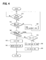
As shown in FIG. 4, at step S10, it is determined whether there is an engine stop signal. When the controller 140 detects the engine stop signal at step S10, it goes to step S20. When the controller 140 does not detect the engine stop signal, i.e., the engine 10 runs, it returns to the start, and the engine 10 drives the compressor 130. At step S20, the controller. 140 determines whether the controller 140 detects the A/C request signal. When the controller 140 does not detect the A/C request signal, e.g., when a passenger selects the A/C off switch 253, the displacement of the compressor 130 becomes minimized at step S30. The compressor 130 needs not to operate, so that the displacement of the compressor 130 is generally zero, at step S30. Then, it returns to the start.
When the controller 140 detects the A/C request signal at step S20, the controller 140 determines at step S40 whether the normal mode signal or the economy mode signal is inputted. When the controller 140 detects the economy mode signal, the engine 10 stops at step S50. Then, the motor 120 drives the compressor 130 at step S60. In this case, the refrigerant cycle system 200 operates economically.
On the other hand, when the controller 140 determines the normal mode at step S40, it is determined at step S70 whether the actual temperature TE is higher than the target temperature TEO. When the actual temperature TE is not higher than the target temperature TEO, it goes to step S50, because the required cooling capacity of the refrigerant cycle system 200 is comparatively low. Similar to the above-mentioned case, the engine 10 stops at step S50, and the motor 120 drives the compressor 130 at step 560.
When the actual temperature TE is higher than the target temperature TEO, the engine 10 continues to run at step S80, and the engine 10 drives the compressor 140 at step S90. In this case, the required cooling capacity of the refrigerant cycle system 200 is comparatively high.
FIG. 5 shows a timing chart of a vehicle speed, an engine speed, the actual temperature TE of the air flowing from the evaporator 230, and a motor drive state. In FIG. 5, R1 shows a reference case where a hybrid compressor is operated and a passenger selects an economy operation switch. In this reference R1, a controller does not determine whether the economy mode signal is input. Therefore, when an actual temperature TE increases, an engine starts and a motor stops, so that the engine drives the compressor.
The solid line in FIG. 5 shows control operation of the first embodiment when the hybrid compressor apparatus 100 is operated and the passenger selects the economy operation switch 252. In this case, even when the actual temperature TE increases more than the target temperature TEO, the engine 10 does not start and the motor 120 runs, so that the motor 120 drives the compressor 130. Therefore, although a generating torque of the motor 120 is limited, the operation load of the compressor 130 can be reduced in the economy mode, which is selected by the passenger. Thus, in this case, the engine 10 does not start, and the motor 120 drives the compressor 130 in the refrigerant cycle system 200 as much as possible, so that a fuel consumption efficiency of the vehicle can be improved.
Second Embodiment
A hybrid compressor apparatus 100 according to the second embodiment will be described with reference to FIGS. 6-8. As shown in FIG. 7, additional new step S55 is added between step S50 and step S60 shown in FIG. 4. At step S55, the target temperature TEO changes when the economic mode is selected. In other words, when a passenger selects the economy operation switch 252, the controller 140 changes the target temperature TEO to a modified target temperature TEO1, which is higher than the target temperature TEO by a predetermined amount ΔT. The modified target temperature TEO1 is shown as a dotted line in FIG. 6.
When the engine 10 stops and the refrigerant cycle system 200 is operated in the economy mode, the target temperature TEO changes to the modified target temperature TEO1, and then the motor 120 drives the compressor 130 so that the refrigerant cycle system 200 is operated. In this case, the operation load of the compressor 130 can be reduced. Therefore, the operation load of the motor 120 for driving the compressor 130 is also reduced, as shown in FIG. 8. In FIG. 8, when the vehicle stops and the engine 10 stops, the actual temperature TE of the air flowing from the evaporator 230 increases. When the actual temperature TE is higher than the target temperature TEO, the motor 130 drives the compressor 130. Then, the controller 140 changes the target temperature TEO to the modified target temperature TEO1 so that the load of the motor 130 is reduced. For example, the motor 130 stops, when the actual temperature TE is lower than the modified target temperature TEO1. On the other hand, when the actual temperature TE is higher than the modified target temperature TEO1, the motor 130 re-starts.
The motor 130 repeats to run and to stop as shown in FIG. 8, so that an energy consumption of the motor 130 can be reduced. In the second embodiment, the other parts are similar to those of the above-described first embodiment.
Third Embodiment
A hybrid compressor apparatus according to the third embodiment will be now described with reference to FIGS. 9 and 10. In the third embodiment, two new steps S100 and S110 are added after step S60 shown in FIG. 4. An acceptable temperature TA is predetermined in the economy mode for the actual temperature TE.
When the engine 10 stops and the motor 120 drives the compressor 130 at step S60, the actual temperature TE of the air flowing from the evaporator 230 increases. At step S100, the controller 140 determines whether the actual temperature TE is higher than the acceptable temperature TA. When the actual temperature TE is not higher than the acceptable temperature TA, the motor 120 drives the compressor 130, and the engine 10 keeps stopping. When the actual temperature TE is higher than the acceptable temperature TA, the motor 120 stops, and the engine 10 starts its operation at step S110. Then, the engine 10 drives the compressor 130 at step S90. Hear, the acceptable temperature TA is an upper limit temperature in a temperature range of the actual temperature TE, where the compressor 130 is operated by the motor 120 in the economy mode.
As shown in FIG. 10, when the vehicle stops and the engine 10 also stops, the actual temperature TE increases, and the motor 120 starts to run and drives the compressor 130. When the actual temperature TE is higher than the acceptable temperature TA, the motor 120 stops, and the engine 10 starts to run so that the engine 10 drives the compressor 130.
In this way, the actual temperature TE does not exceed the acceptable temperature TA. Therefore, a passenger can drive a vehicle comfortably. In the third embodiment, the other parts are similar to those of the above-described first embodiment.
Modifications
Although the actual temperature TE and the target temperature TEO are temperatures of the air flowing from the evaporator 230, another definition of the actual temperature TE and the target temperature TEO can be used in this invention. For example, the actual temperature TE is defined as a temperature of the air blown from a blowing outlet of an air conditioning unit into the passenger compartment or a temperature in a passenger compartment. Although the target temperature TEO is determined by the temperature of the outside air outside the passenger compartment, another determination of the target temperature TEO can be used in this invention. For example, the target temperature TEO is determined by a setting temperature that is set by a passenger or by environmental conditions.
Although the one-way clutch 150 is used in the hybrid compressor 101, an electromagnetic clutch can be used in the hybrid compressor 101. In this case, the displacement of the compressor may be fixed. That is, the compressor 130 maybe a fixed displacement type compressor.
Moreover, the hybrid compressor apparatus 100 can be applied to an idle stop vehicle, where an engine stops when the vehicle temporally stops such as a case at traffic lights.
Such changes and modifications are to be understood as being within the scope of the present invention as defined by the appended claims.

Claims (7)

What is claimed is:
1. A hybrid compressor apparatus for a refrigerant cycle of a vehicle having an engine that stops in accordance with driving conditions of the vehicle, the hybrid compressor apparatus comprising:
an electrical motor;
a compressor driven by at least one of the engine and the motor, for compressing refrigerant in the refrigerant cycle;
a controller for controlling operation of the motor and the compressor, the controller selecting a driving source between the engine and the motor so as to drive the compressor; and
a switch manually operated by a passenger of a passenger compartment so that the refrigerant cycle is operated in a normal mode or in an economy mode, wherein:
the controller has a detecting unit for detecting an actual temperature at a predetermined position of the passenger compartment, and a determining means for determining a target temperature based on at least one of a setting temperature set by the passenger and the environmental conditions of the vehicle, and
in the economy mode, while the engine is stopped, the controller selects the motor as the driving source and the motor drives the compressor even when the actual temperature is higher than the target temperature.
2. The hybrid compressor apparatus according to claim 1, wherein, in the economy mode, the controller changes the target temperature to a modified target temperature that is higher than the target temperature by a predetermined amount.
3. The hybrid compressor apparatus according to claim 1, wherein:
the controller has a determining means for determining an acceptable temperature that is an upper limit temperature when the compressor is driven by the motor in the economy mode; and
when the actual temperature exceeds the acceptable temperature in the economy mode, the controller requests the engine to start and the motor to stop so that the compressor is driven by the engine.
4. The hybrid compressor apparatus according to claim 1, wherein, when the actual temperature is higher than the target temperature in the normal mode, the compressor is operated by the engine.
5. The hybrid compressor apparatus according to claim 1, wherein, when the actual temperature is not higher than the target temperature in the normal mode, the compressor is operated by the motor.
6. A method of controlling a hybrid compressor apparatus for a refrigerant cycle in a vehicle having an engine that stops in accordance with driving conditions of the vehicle, wherein the hybrid compressor apparatus includes a compressor driven by at least one of the engine and an electrical motor for compressing refrigerant in the refrigerant cycle, the method comprising:
determining whether the engine is stopped;
determining whether a switch is manually selected to a normal mode or an economy mode; and
controlling operation of the motor and the compressor, wherein:
in the controlling, when the economy mode is set while the engine is stopped, the motor drives the compressor even when an actual temperature at a predetermined position of a passenger compartment is higher than a target temperature, which is determined based on at least one of a setting temperature set by the passenger and environmental conditions of the vehicle; and
when the economy mode is determined, the target temperature is changed to a modified target temperature that is higher than the target temperature by a predetermined amount.
7. A method of controlling a hybrid compressor apparatus for a refrigerant cycle in a vehicle having an engine that stops in accordance with driving conditions of the vehicle, wherein the hybrid compressor apparatus includes a compressor driven by at least one of the engine and an electrical motor for compressing refrigerant in the refrigerant cycle, the method comprising:
determining whether the engine is stopped;
determining whether a switch is manually selected to a normal mode or an economy mode;
controlling operation of the motor and the compressor, wherein, in the controlling when the economy mode is set while the engine is stopped, the motor drives the compressor even when an actual temperature at a predetermined position of a passenger compartment is higher than a target temperature, which is determined based on at least one of a setting temperature set by the passenger and environmental conditions of the vehicle;
determining whether the actual temperature exceeds an acceptable temperature when the engine stops and the refrigerant cycle is operated in the economy mode; and
requesting the engine to start and the motor to stop so that the engine drives the compressor when the actual temperature exceeds the acceptable temperature.
US10/443,798 2002-06-12 2003-05-23 Hybrid compressor apparatus and method of controlling the same Expired - Lifetime US6755033B2 (en)

Applications Claiming Priority (2)

Application Number Priority Date Filing Date Title
JP2002171094A JP3775351B2 (en) 2002-06-12 2002-06-12 HYBRID COMPRESSOR DEVICE AND HYBRID COMPRESSOR CONTROL METHOD
JP2002-171094 2002-06-12

Publications (2)

Publication Number Publication Date
US20030230093A1 US20030230093A1 (en) 2003-12-18
US6755033B2 true US6755033B2 (en) 2004-06-29

Family

ID=29706908

Family Applications (1)

Application Number Title Priority Date Filing Date
US10/443,798 Expired - Lifetime US6755033B2 (en) 2002-06-12 2003-05-23 Hybrid compressor apparatus and method of controlling the same

Country Status (3)

Country Link
US (1) US6755033B2 (en)
JP (1) JP3775351B2 (en)
DE (1) DE10326169A1 (en)

Cited By (11)

* Cited by examiner, † Cited by third party
Publication number Priority date Publication date Assignee Title
US20040112074A1 (en) * 2002-12-13 2004-06-17 Masato Komura Vehicle air conditioner
US20050044873A1 (en) * 2003-08-28 2005-03-03 Goro Tamai Climate cooling control systems and methods for hybrid vehicles
US20050109499A1 (en) * 2001-04-27 2005-05-26 Shigeki Iwanami Air-conditioning apparatus including motor-driven compressor for idle stopping vehicles
WO2006015429A1 (en) * 2004-08-09 2006-02-16 Kool Ideas Pty Ltd Air-conditioning
US20070188964A1 (en) * 2006-02-16 2007-08-16 Kazuhi Yamaguchi Feed limiting device for limiting feedings to electrical components and control device
US20080006711A1 (en) * 2004-12-27 2008-01-10 Toyota Jidosha Kabushiki Kaisha Vehicle and Method for Controlling Same
US20080041078A1 (en) * 2006-08-17 2008-02-21 Yong-Kak Choi Method of controlling air conditioner in hybrid car
US20090150025A1 (en) * 2007-12-10 2009-06-11 Honda Motor Co., Ltd. Controller for vehicle
US20120060522A1 (en) * 2010-09-10 2012-03-15 Ford Global Technologies, Llc Method for controlling an air conditioning system
US9102225B2 (en) * 2007-10-31 2015-08-11 GM Global Technology Operations LLC Air conditioning for belt-alternator-starter hybrid electric vehicle
US11577581B2 (en) 2016-06-24 2023-02-14 Cummins Inc. Apparatus and system for controlling power to an air conditioning compressor for a vehicle

Families Citing this family (13)

* Cited by examiner, † Cited by third party
Publication number Priority date Publication date Assignee Title
EP1571022B1 (en) * 2004-03-03 2007-09-26 Mazda Motor Corporation Vehicle control system including an air conditioning system
CN100413728C (en) * 2004-11-18 2008-08-27 丰田自动车株式会社 Vehicle
US8234025B2 (en) * 2006-11-28 2012-07-31 GM Global Technology Operations LLC Control system for a hybrid powertrain system
KR101272591B1 (en) * 2007-12-12 2013-06-11 기아자동차주식회사 Air conditioner driving system of hybrid electric vehicle
JP5125752B2 (en) * 2008-05-14 2013-01-23 トヨタ自動車株式会社 Hybrid vehicle and control method thereof
KR101496645B1 (en) 2008-08-20 2015-02-27 한라비스테온공조 주식회사 Control method and apparatus for cut-off temperature of compressor of air conditioner in vehicle
JP5012786B2 (en) * 2008-12-22 2012-08-29 三菱自動車工業株式会社 Air conditioner for vehicles
EP2464920B1 (en) * 2009-08-10 2019-05-22 Carrier Corporation Power savings apparatus for transport refrigeration system, transport refrigeration unit, and methods for same
US8745997B2 (en) 2011-06-02 2014-06-10 Ford Global Technologies, Llc Optimized cooling for vehicle with start-stop technology
KR101796121B1 (en) * 2011-06-17 2017-12-01 콘티넨탈 오토모티브 시스템 주식회사 Method for improving fuel efficiency of vehicle and running performance, and apparatus applied to the same
KR101976820B1 (en) * 2012-09-18 2019-08-28 현대모비스 주식회사 air conditioner system of hybrid vehicle for minimizing engine output and fuel consumption and control method of the air conditioner system
GB2512891B (en) * 2013-04-10 2018-05-30 Ford Global Tech Llc A Method of Controlling the stop-start system of an Engine of a Motor Vehicle
KR101588746B1 (en) * 2014-09-05 2016-01-26 현대자동차 주식회사 Hybrid compressor

Citations (15)

* Cited by examiner, † Cited by third party
Publication number Priority date Publication date Assignee Title
US5934089A (en) * 1997-03-05 1999-08-10 Toyota Jidosha Kabushiki Kaisha Air conditioning controller for a hybrid car
JP2000130323A (en) 1998-10-29 2000-05-12 Zexel Corp Hybrid compressor
US6073456A (en) * 1997-10-09 2000-06-13 Denso Corporation Air-conditioning device for hybrid vehicle
JP2000289454A (en) 1999-04-09 2000-10-17 Denso Corp Idling stop controller for vehicle with air conditioning system
US6425838B1 (en) * 1999-09-20 2002-07-30 Hitachi, Ltd. Motor/generator apparatus for motor vehicle
US6427472B1 (en) * 1996-10-01 2002-08-06 Toyota Jidosha Kabushiki Kaisha Air conditioner for a vehicle
US6459166B2 (en) * 2000-02-16 2002-10-01 Mitsubishi Jidosha Kogyo Kabushiki Kaisha Warm-up control device of hybrid electric vehicle
US6470697B2 (en) * 2000-04-27 2002-10-29 Denso Corporation Air-conditioning system for vehicles
US6481225B2 (en) * 2000-08-09 2002-11-19 Kabushiki Kaisha Toyota Jidoshokki Air conditioning apparatus for vehicle and its control method
US6500089B2 (en) * 2000-10-31 2002-12-31 Ford Global Technologies, Inc. Method and arrangement in a hybrid vehicle for maximizing efficiency by operating the engine at sub-optimum conditions
US6515448B2 (en) * 2000-12-28 2003-02-04 Denso Corporation Air conditioner for hybrid vehicle
US6516621B2 (en) * 2001-01-16 2003-02-11 Denso Corporation Air conditioner for hybrid vehicle
JP2003056310A (en) * 2001-08-13 2003-02-26 Takeshi Hatanaka Hybrid engine, hybrid power system, hybrid vehicle and driving method of hybrid vehicle
US6543243B2 (en) * 2001-06-21 2003-04-08 Visteon Global Technologies, Inc. Hybrid compressor
US6554088B2 (en) * 1998-09-14 2003-04-29 Paice Corporation Hybrid vehicles

Patent Citations (15)

* Cited by examiner, † Cited by third party
Publication number Priority date Publication date Assignee Title
US6427472B1 (en) * 1996-10-01 2002-08-06 Toyota Jidosha Kabushiki Kaisha Air conditioner for a vehicle
US5934089A (en) * 1997-03-05 1999-08-10 Toyota Jidosha Kabushiki Kaisha Air conditioning controller for a hybrid car
US6073456A (en) * 1997-10-09 2000-06-13 Denso Corporation Air-conditioning device for hybrid vehicle
US6554088B2 (en) * 1998-09-14 2003-04-29 Paice Corporation Hybrid vehicles
JP2000130323A (en) 1998-10-29 2000-05-12 Zexel Corp Hybrid compressor
JP2000289454A (en) 1999-04-09 2000-10-17 Denso Corp Idling stop controller for vehicle with air conditioning system
US6425838B1 (en) * 1999-09-20 2002-07-30 Hitachi, Ltd. Motor/generator apparatus for motor vehicle
US6459166B2 (en) * 2000-02-16 2002-10-01 Mitsubishi Jidosha Kogyo Kabushiki Kaisha Warm-up control device of hybrid electric vehicle
US6470697B2 (en) * 2000-04-27 2002-10-29 Denso Corporation Air-conditioning system for vehicles
US6481225B2 (en) * 2000-08-09 2002-11-19 Kabushiki Kaisha Toyota Jidoshokki Air conditioning apparatus for vehicle and its control method
US6500089B2 (en) * 2000-10-31 2002-12-31 Ford Global Technologies, Inc. Method and arrangement in a hybrid vehicle for maximizing efficiency by operating the engine at sub-optimum conditions
US6515448B2 (en) * 2000-12-28 2003-02-04 Denso Corporation Air conditioner for hybrid vehicle
US6516621B2 (en) * 2001-01-16 2003-02-11 Denso Corporation Air conditioner for hybrid vehicle
US6543243B2 (en) * 2001-06-21 2003-04-08 Visteon Global Technologies, Inc. Hybrid compressor
JP2003056310A (en) * 2001-08-13 2003-02-26 Takeshi Hatanaka Hybrid engine, hybrid power system, hybrid vehicle and driving method of hybrid vehicle

Cited By (19)

* Cited by examiner, † Cited by third party
Publication number Priority date Publication date Assignee Title
US20050109499A1 (en) * 2001-04-27 2005-05-26 Shigeki Iwanami Air-conditioning apparatus including motor-driven compressor for idle stopping vehicles
US7287583B2 (en) * 2001-04-27 2007-10-30 Denso Corporation Air-conditioning apparatus including motor-driven compressor for idle stopping vehicles
US20040112074A1 (en) * 2002-12-13 2004-06-17 Masato Komura Vehicle air conditioner
US6892549B2 (en) * 2002-12-13 2005-05-17 Denso Corporation Vehicle air conditioner
US20050044873A1 (en) * 2003-08-28 2005-03-03 Goro Tamai Climate cooling control systems and methods for hybrid vehicles
US7032393B2 (en) * 2003-08-28 2006-04-25 General Motors Corporation Climate cooling control systems and methods for hybrid vehicles
WO2006015429A1 (en) * 2004-08-09 2006-02-16 Kool Ideas Pty Ltd Air-conditioning
US20080307820A1 (en) * 2004-08-09 2008-12-18 Terry David Ingram Air-Conditioning
US20080006711A1 (en) * 2004-12-27 2008-01-10 Toyota Jidosha Kabushiki Kaisha Vehicle and Method for Controlling Same
US8561915B2 (en) * 2004-12-27 2013-10-22 Toyota Jidosha Kabushiki Kaisha Vehicle and method for controlling same
US20070188964A1 (en) * 2006-02-16 2007-08-16 Kazuhi Yamaguchi Feed limiting device for limiting feedings to electrical components and control device
US7629706B2 (en) * 2006-02-16 2009-12-08 Fujitsu Ten Limited Feed limiting device for limiting feed to electrical components and control device
US20080041078A1 (en) * 2006-08-17 2008-02-21 Yong-Kak Choi Method of controlling air conditioner in hybrid car
US9102225B2 (en) * 2007-10-31 2015-08-11 GM Global Technology Operations LLC Air conditioning for belt-alternator-starter hybrid electric vehicle
US20090150025A1 (en) * 2007-12-10 2009-06-11 Honda Motor Co., Ltd. Controller for vehicle
US8285443B2 (en) * 2007-12-10 2012-10-09 Honda Motor Co., Ltd. Controller for vehicle
US20120060522A1 (en) * 2010-09-10 2012-03-15 Ford Global Technologies, Llc Method for controlling an air conditioning system
US8850834B2 (en) * 2010-09-10 2014-10-07 Ford Global Technologies, Llc Method for controlling an air conditioning system
US11577581B2 (en) 2016-06-24 2023-02-14 Cummins Inc. Apparatus and system for controlling power to an air conditioning compressor for a vehicle

Also Published As

Publication number Publication date
JP3775351B2 (en) 2006-05-17
JP2004017666A (en) 2004-01-22
DE10326169A1 (en) 2003-12-24
US20030230093A1 (en) 2003-12-18

Similar Documents

Publication Publication Date Title
US6755033B2 (en) Hybrid compressor apparatus and method of controlling the same
US6986645B2 (en) Hybrid compressor with a selective drive clutch means and speed increasing means for driving the compressor at higher speeds with an engine at high load regions
US6745585B2 (en) Electric air conditioner sustain system
US6761037B2 (en) Vehicle air conditioner using a hybrid compressor
US6823690B2 (en) Integrated electrical generator/starter and air conditioning compressor device and system and method for controlling same
US6688121B2 (en) Controlled compressor apparatus
US6830438B2 (en) Hybrid compressor
US6927500B2 (en) Automotive accessories control system
JP2003312239A (en) Hybrid auxiliary power unit for vehicle and controlling device therefor
JP3955504B2 (en) Method for starting hybrid compressor for vehicle air conditioner
US7207784B2 (en) Hybrid compressor and control device
JP2002370529A (en) Air-conditioner for vehicle
KR20190002123A (en) Air conditioning system for commercial vehicle and control method thereof
JP2000229516A (en) Controller for hybrid compressor
JP4156955B2 (en) Driving method of hybrid compressor for vehicle air conditioner
US6820438B2 (en) Vehicle air conditioner
JPH11101514A (en) Refrigeration cycle
JP2008302721A (en) Vehicular air-conditioning control device
JP2004231097A (en) Air-conditioning control device for vehicle
JP2004098975A (en) Air conditioner for vehicle
JP4275374B2 (en) Compressor control device
JP3552910B2 (en) Compressor control device for hybrid electric vehicle
JP2003021059A (en) Hybrid compressor device
JP2004122814A (en) Vehicular air conditioner
JP2000211348A (en) Automotive air conditioning device

Legal Events

Date Code Title Description
AS Assignment

Owner name: DENSO CORPORATION, JAPAN

Free format text: ASSIGNMENT OF ASSIGNORS INTEREST;ASSIGNORS:IWANAMI, SHIGEKI;UNO, KEIICHI;REEL/FRAME:014113/0008

Effective date: 20030512

STCF Information on status: patent grant

Free format text: PATENTED CASE

FEPP Fee payment procedure

Free format text: PAYOR NUMBER ASSIGNED (ORIGINAL EVENT CODE: ASPN); ENTITY STATUS OF PATENT OWNER: LARGE ENTITY

FPAY Fee payment

Year of fee payment: 4

FPAY Fee payment

Year of fee payment: 8

FEPP Fee payment procedure

Free format text: PAYOR NUMBER ASSIGNED (ORIGINAL EVENT CODE: ASPN); ENTITY STATUS OF PATENT OWNER: LARGE ENTITY

Free format text: PAYER NUMBER DE-ASSIGNED (ORIGINAL EVENT CODE: RMPN); ENTITY STATUS OF PATENT OWNER: LARGE ENTITY

FPAY Fee payment

Year of fee payment: 12