US6739795B1 - Telescoping trough - Google Patents
Telescoping trough Download PDFInfo
- Publication number
- US6739795B1 US6739795B1 US09/578,300 US57830000A US6739795B1 US 6739795 B1 US6739795 B1 US 6739795B1 US 57830000 A US57830000 A US 57830000A US 6739795 B1 US6739795 B1 US 6739795B1
- Authority
- US
- United States
- Prior art keywords
- trough section
- trough
- receiving end
- section
- upright walls
- Prior art date
- Legal status (The legal status is an assumption and is not a legal conclusion. Google has not performed a legal analysis and makes no representation as to the accuracy of the status listed.)
- Expired - Lifetime
Links
Images


Classifications
-
- G—PHYSICS
- G02—OPTICS
- G02B—OPTICAL ELEMENTS, SYSTEMS OR APPARATUS
- G02B6/00—Light guides; Structural details of arrangements comprising light guides and other optical elements, e.g. couplings
- G02B6/44—Mechanical structures for providing tensile strength and external protection for fibres, e.g. optical transmission cables
- G02B6/4439—Auxiliary devices
- G02B6/4459—Ducts; Conduits; Hollow tubes for air blown fibres
-
- H—ELECTRICITY
- H02—GENERATION; CONVERSION OR DISTRIBUTION OF ELECTRIC POWER
- H02G—INSTALLATION OF ELECTRIC CABLES OR LINES, OR OF COMBINED OPTICAL AND ELECTRIC CABLES OR LINES
- H02G9/00—Installations of electric cables or lines in or on the ground or water
- H02G9/04—Installations of electric cables or lines in or on the ground or water in surface ducts; Ducts or covers therefor
-
- Y—GENERAL TAGGING OF NEW TECHNOLOGICAL DEVELOPMENTS; GENERAL TAGGING OF CROSS-SECTIONAL TECHNOLOGIES SPANNING OVER SEVERAL SECTIONS OF THE IPC; TECHNICAL SUBJECTS COVERED BY FORMER USPC CROSS-REFERENCE ART COLLECTIONS [XRACs] AND DIGESTS
- Y10—TECHNICAL SUBJECTS COVERED BY FORMER USPC
- Y10T—TECHNICAL SUBJECTS COVERED BY FORMER US CLASSIFICATION
- Y10T29/00—Metal working
- Y10T29/49—Method of mechanical manufacture
- Y10T29/49616—Structural member making
- Y10T29/49623—Static structure, e.g., a building component
-
- Y—GENERAL TAGGING OF NEW TECHNOLOGICAL DEVELOPMENTS; GENERAL TAGGING OF CROSS-SECTIONAL TECHNOLOGIES SPANNING OVER SEVERAL SECTIONS OF THE IPC; TECHNICAL SUBJECTS COVERED BY FORMER USPC CROSS-REFERENCE ART COLLECTIONS [XRACs] AND DIGESTS
- Y10—TECHNICAL SUBJECTS COVERED BY FORMER USPC
- Y10T—TECHNICAL SUBJECTS COVERED BY FORMER US CLASSIFICATION
- Y10T29/00—Metal working
- Y10T29/49—Method of mechanical manufacture
- Y10T29/49826—Assembling or joining
- Y10T29/4984—Retaining clearance for motion between assembled parts
-
- Y—GENERAL TAGGING OF NEW TECHNOLOGICAL DEVELOPMENTS; GENERAL TAGGING OF CROSS-SECTIONAL TECHNOLOGIES SPANNING OVER SEVERAL SECTIONS OF THE IPC; TECHNICAL SUBJECTS COVERED BY FORMER USPC CROSS-REFERENCE ART COLLECTIONS [XRACs] AND DIGESTS
- Y10—TECHNICAL SUBJECTS COVERED BY FORMER USPC
- Y10T—TECHNICAL SUBJECTS COVERED BY FORMER US CLASSIFICATION
- Y10T29/00—Metal working
- Y10T29/49—Method of mechanical manufacture
- Y10T29/49826—Assembling or joining
- Y10T29/49904—Assembling a subassembly, then assembling with a second subassembly
-
- Y—GENERAL TAGGING OF NEW TECHNOLOGICAL DEVELOPMENTS; GENERAL TAGGING OF CROSS-SECTIONAL TECHNOLOGIES SPANNING OVER SEVERAL SECTIONS OF THE IPC; TECHNICAL SUBJECTS COVERED BY FORMER USPC CROSS-REFERENCE ART COLLECTIONS [XRACs] AND DIGESTS
- Y10—TECHNICAL SUBJECTS COVERED BY FORMER USPC
- Y10T—TECHNICAL SUBJECTS COVERED BY FORMER US CLASSIFICATION
- Y10T403/00—Joints and connections
- Y10T403/71—Rod side to plate or side
- Y10T403/7117—Flanged or grooved rod
Definitions
- This application relates to a system for the management and routing of optical fiber cables and other telecommunications cables. Particularly, this application relates to a trough member for use with other troughs, couplings, and fittings.
- optical fibers for signal transmissions
- optical fiber cable management requires industry attention.
- optical fiber management One area of optical fiber management that is necessary is the routing of optical fibers from one piece of equipment to another.
- optical fiber cables may be routed between fiber distribution equipment and optical line terminating equipment.
- the cable routing can take place in concealed ceiling areas or in any other manner to route cables from one location to another.
- routing systems include a plurality of trough members such as troughs and couplings for forming the cable routing paths.
- the trough system members are joined together by couplings.
- U.S. Pat. No. 5,067,678 to Henneberger et al dated Nov. 26, 1991 concerns a cable routing system that includes a plurality of troughs and fittings.
- the '678 patent further discloses a coupling (element 250 in FIG. 1 of the '678 patent) for joining trough members and fittings.
- a plurality of hardware is disclosed for joining the trough members.
- U.S. Pat. Nos. 5,316,243 and 5,752,781 show additional examples of couplings.
- the present invention relates to a telescoping cable trough section for a cable routing system.
- the cable trough section includes first and second U-shaped trough sections extending in a longitudinal direction and each including a terminal end and a receiving end.
- the receiving ends are slideably mated for sliding movement along the longitudinal direction.
- the terminal ends can be joined to other system components, including couplings for joining to other trough sections or fittings in the cable routing system.
- the terminal ends of the first and second trough sections include ends shaped to mate with the same coupling.
- the terminal ends define the same coupling profile.
- each of the first and second trough sections includes two upright walls.
- One of the first and second trough sections includes longitudinal slots formed in the upright walls.
- the other of the first and second trough sections includes longitudinal flanges on the upright walls which are slideably received in the longitudinal slots of the other trough section.
- a retention system retains the first and second trough sections together so that the parts do not slide apart before installation in the system.
- FIG. 1 is a top perspective view of a portion of a cable routing system, including a telescoping trough in accordance with the present invention, and a horizontal trough section, and a fitting as exemplary components used with the telescoping trough;
- FIG. 2 is a top perspective view of the telescoping trough of FIG. 1;
- FIG. 3 is a bottom perspective view of the telescoping trough
- FIG. 4 is a side view of the telescoping trough
- FIG. 5 is a top view of the telescoping trough
- FIG. 6 is a bottom view of the telescoping trough
- FIG. 7 is a top perspective view of the telescoping trough in a retracted state
- FIG. 8 is a side view of the telescoping trough of FIG. 7;
- FIG. 9 is a cross-sectional end view of the telescoping trough, taken along lines 9 — 9 of FIG. 8;
- FIG. 10 is a top perspective view of the first trough section of the telescoping trough
- FIG. 11 is a side view of the first trough section
- FIG. 12 is a cross-sectional end view of the telescoping trough, taken along lines 12 — 12 of FIG. 11;
- FIG. 13 is a top perspective view of the second trough section of the telescoping trough
- FIG. 14 is a bottom perspective view of the second trough section
- FIG. 15 is a side view of the second trough section
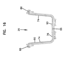
- FIG. 16 is a cross-sectional end view of the second trough section, taken along lines 16 — 16 of FIG. 15 .
- Cable routing system 10 includes a telescoping trough 12 mounted to a coupling 14 on one terminal end 30 .
- Coupling 14 joins telescoping trough 12 to horizontal trough section 16 .
- An opposite terminal end 32 of telescoping trough 12 is mounted to a second coupling 14 which is mounted to a fitting 18 (T-fitting).
- End 30 can be spaced from end 32 in a telescoping manner.
- Couplings 14 are described in greater detail in U.S. Pat. No. 5,752,781, the disclosure of which is incorporated by reference. Terminal ends 30 , 32 are received in generally U-shaped channels in couplings 14 . Resilient tabs 14 a engage holes 29 in terminal ends 30 , 32 . Fasteners 14 b of coupling 14 are screwed down to secure couplings 14 to trough 12 . Cable retention members 14 c are added to help retain the cables in the various trough and fitting components. Additional couplings, troughs and fittings useful in system 10 with trough 12 are disclosed in U.S. Pat. Nos. 5,067,678; 5,316,243; 5,923,753 and 5,937,131, the disclosures of which are also incorporated by reference.
- Telescoping trough 12 has a variable or changeable length so as to be usable in a variety of circumstances in system 10 or other systems. Trough 12 is useful in system 10 where the distance between couplings 14 is any distance between a maximum and minimum for the amount of extension for telescoping trough 12 . This allows for less precise design and assembly of system 10 . Instead of telescoping trough 12 , a single piece trough would have to be custom cut or manufactured to fit between couplings 14 .
- telescoping trough 12 can drop into position between couplings 14 , in a slightly retracted state, and then be expanded to complete the cable pathway between couplings 14 . Once expanded, resilient tabs 14 a, and fasteners 14 b secure trough 12 in place. Further, system 10 can be accessed for modification by releasing tabs 14 a, and fasteners 14 b, and then retracting telescoping trough 12 to allow its removal.
- Telescoping trough 12 includes a first trough section 24 and a second trough section 26 which are slideably mated with one another.
- First trough section 24 and second trough section 26 include a variable overlap portion 28 (compare FIGS. 5 and 8 ).
- Terminal ends 30 , 32 of telescoping trough 12 each join to one of couplings 14 .
- Terminal ends 30 , 32 each have a profile which permits either end 30 , 32 to be mated with either coupling 14 .
- Such a shaping for the ends allows ease of assembly since trough 12 can be inserted in either orientation for ends 30 , 32 .
- the end profiles of trough 12 are identical.
- Terminal ends 30 , 32 also mate with other couplings or fittings as desired.
- Telescoping trough 12 defines a generally U-shaped channel with upright walls 34 extending from a base wall 36 .
- Interior 35 defines the cable pathway for the optical fiber (or copper) cables.
- First trough section 24 includes a receiving end 40 , and an opposite terminal end 42 .
- First trough section 24 defines a generally U-shaped channel including upright wall sections 44 extending from a base wall section 46 .
- First trough section 24 includes an outside surface 48 and an inside surface 50 .
- Outside surface 48 can include a variety of shapes including strengthening ribs 49 and structure 51 for mounting to system support hardware which holds system 10 in place, such as in a ceiling mount.
- First trough section 24 includes upper flanges 52 at an upper portion of upright wall sections 44 each defining a slot 54 for mating with portions of second trough section 26 , as will be described below in further detail.
- Base wall section 46 further includes a projecting tab 56 facing upwardly.
- Tab 56 includes a ramp surface 58 , and a shoulder 60 .
- Tab 56 is used to retain first and second trough sections 24 , 26 together, as will be described below in further detail.
- Second trough section 26 includes a receiving end 70 , and an opposite terminal end 72 .
- Upright wall sections 74 extend from base wall section 76 .
- Second trough section 26 includes an outside surface 78 and an inside surface 80 .
- upper flanges 82 extend outwardly for receipt in slots 54 of first trough section 24 .
- inside surface 50 of first trough section 24 closely receives outside surface 78 of second trough section 26 .
- Inside surface 80 and the exposed inside surface 50 not covered by second trough section 26 form a closed U-shaped trough for receipt of the cables passing through trough 12 .
- Flanges 82 each include small upper ridges 84 extending perpendicularly to flanges 82 to assist with a secure fit of flanges 82 in slots 54 . Ridges 84 help fill the height of slots 54 , yet do not promote binding of the parts during sliding movement (see FIG. 9 ).
- Base wall section 76 of second trough section 26 includes an elongated slot 86 for receipt of tab 56 of first trough section 24 (see FIG. 9 ).
- the interaction of tab 56 and slot 86 keeps second trough section 26 from being separated from first trough section 24 and further defines the maximum length of trough 12 .
- Ramp surface 58 allows for the two trough sections 24 , 26 to be mounted together during assembly by aligning the two parts (receiving end 70 inside receiving end 40 , and flanges 82 aligned with slots 54 ) and pressing them together in the axial direction. Once tab 56 is positioned in slot 86 , shoulder 60 prevents the two pieces from being separated.
- first and second trough sections 24 , 26 are made from molded plastic. Tab 56 can be separated from slot 86 by manually pressing base wall section 46 away from base wall section 76 .
- Base wall section 76 of second trough section 26 preferably includes a middle thickened area 90 , which allows for convenient molding from plastic.
- Middle thickened area 90 provides an increased thickness in portions of second trough section 26 adjacent to slot 86 .
- Thickened area 90 promotes material flow during molding.
- Receiving end 70 of second trough section 26 preferably includes a tapered receiving end 94 , to help protect fiber optic cables contained within telescoping trough 12 from contacting any sharp edges. End 94 tapers to a minimum wall thickness at end 70 .
- Second trough section 26 further includes an enlarged terminal end 98 relative to a reduced central section 99 and receiving end 70 which allows for terminal end 72 to have a similar coupling profile as terminal end 42 of first trough section 24 .
- Enlarged terminal end 98 also provides a stop for limiting the minimum length of trough 12 .
Abstract
Description
Claims (43)
Priority Applications (5)
| Application Number | Priority Date | Filing Date | Title |
|---|---|---|---|
| US09/578,300 US6739795B1 (en) | 2000-05-25 | 2000-05-25 | Telescoping trough |
| EP01972912A EP1360535A2 (en) | 2000-05-25 | 2001-05-25 | Telescoping trough |
| AU2001292543A AU2001292543A1 (en) | 2000-05-25 | 2001-05-25 | Telescoping trough |
| PCT/US2001/017149 WO2001095003A2 (en) | 2000-05-25 | 2001-05-25 | Telescoping trough |
| US10/626,106 US7383634B2 (en) | 2000-05-25 | 2003-07-23 | Method of assembling a cable routing system |
Applications Claiming Priority (1)
| Application Number | Priority Date | Filing Date | Title |
|---|---|---|---|
| US09/578,300 US6739795B1 (en) | 2000-05-25 | 2000-05-25 | Telescoping trough |
Related Child Applications (1)
| Application Number | Title | Priority Date | Filing Date |
|---|---|---|---|
| US10/626,106 Division US7383634B2 (en) | 2000-05-25 | 2003-07-23 | Method of assembling a cable routing system |
Publications (1)
| Publication Number | Publication Date |
|---|---|
| US6739795B1 true US6739795B1 (en) | 2004-05-25 |
Family
ID=24312272
Family Applications (2)
| Application Number | Title | Priority Date | Filing Date |
|---|---|---|---|
| US09/578,300 Expired - Lifetime US6739795B1 (en) | 2000-05-25 | 2000-05-25 | Telescoping trough |
| US10/626,106 Expired - Fee Related US7383634B2 (en) | 2000-05-25 | 2003-07-23 | Method of assembling a cable routing system |
Family Applications After (1)
| Application Number | Title | Priority Date | Filing Date |
|---|---|---|---|
| US10/626,106 Expired - Fee Related US7383634B2 (en) | 2000-05-25 | 2003-07-23 | Method of assembling a cable routing system |
Country Status (4)
| Country | Link |
|---|---|
| US (2) | US6739795B1 (en) |
| EP (1) | EP1360535A2 (en) |
| AU (1) | AU2001292543A1 (en) |
| WO (1) | WO2001095003A2 (en) |
Cited By (15)
| Publication number | Priority date | Publication date | Assignee | Title |
|---|---|---|---|---|
| US20040051007A1 (en) * | 2000-06-01 | 2004-03-18 | Bernard William A. | Cable duct coupler |
| US20040124321A1 (en) * | 2000-09-26 | 2004-07-01 | Adc Telecommunications Inc. | Cable trough method with separate side elements |
| US20070092196A1 (en) * | 2005-10-07 | 2007-04-26 | Yilmaz Bayazit | Cable trough system and method |
| US20070175967A1 (en) * | 2006-01-27 | 2007-08-02 | Narasimha-Rao Venkata Bangaru | High integrity welding and repair of metal components |
| US20070181647A1 (en) * | 2006-01-27 | 2007-08-09 | Ford Steven J | Application of high integrity welding and repair of metal components in oil and gas exploration, production and refining |
| US20080181568A1 (en) * | 2007-01-26 | 2008-07-31 | Derek Sayres | Cable trough system and method |
| US20080185483A1 (en) * | 2006-06-21 | 2008-08-07 | Adc Telecommunications, Inc. | Cable Routing Devices with Integrated Couplers |
| US20090169164A1 (en) * | 2007-12-07 | 2009-07-02 | Derek Sayres | Flexible cover for cable trough system |
| US20090189025A1 (en) * | 2007-12-07 | 2009-07-30 | Ryan Lindquist | Telescoping cover for cable trough system |
| US20090196564A1 (en) * | 2008-02-05 | 2009-08-06 | Owens Ryan J | Fiber Routing System With Drop-In Device |
| US7627224B1 (en) * | 2008-12-24 | 2009-12-01 | At&T Intellectual Property I, L.P. | Cabinet fiber manager |
| US20100006317A1 (en) * | 2007-07-09 | 2010-01-14 | Adc Telecommunications, Inc. | Telecommunications frame including an internal cable trough assembly |
| US20110006022A1 (en) * | 2009-05-19 | 2011-01-13 | Panduit Corp. | Telescoping Wire Cable Tray System |
| US10128642B2 (en) | 2016-06-08 | 2018-11-13 | Thomas & Betts International Llc | Foldable cable tray |
| US11646556B2 (en) | 2019-10-17 | 2023-05-09 | Panduit Corp. | Raceway system |
Families Citing this family (7)
| Publication number | Priority date | Publication date | Assignee | Title |
|---|---|---|---|---|
| DE10235261B3 (en) * | 2002-08-01 | 2004-04-01 | Eldon Holding Ab | cable storage |
| US7481597B2 (en) * | 2007-02-21 | 2009-01-27 | Adc Telecommunications, Inc. | Coupler for cable trough |
| KR200451561Y1 (en) * | 2008-05-28 | 2010-12-21 | 현대제철 주식회사 | Connecting structure for trough |
| US8136769B2 (en) * | 2009-09-30 | 2012-03-20 | Thomas & Betts International, Inc. | Cable tray support assembly |
| US20120211115A1 (en) * | 2011-02-22 | 2012-08-23 | Straughn Joseph W | Pipe enclosure apparatus |
| JP2016120901A (en) * | 2014-12-24 | 2016-07-07 | 株式会社オートネットワーク技術研究所 | Automotive power feeder |
| EP3365715B1 (en) | 2015-10-19 | 2020-12-02 | Commscope Technologies LLC | Articulating optical fiber guide system |
Citations (35)
| Publication number | Priority date | Publication date | Assignee | Title |
|---|---|---|---|---|
| US689894A (en) | 1901-05-23 | 1901-12-31 | Emmett D Page | Elbow for conduits for electric wires. |
| US1986965A (en) | 1929-09-26 | 1935-01-08 | Bulldog Electric Prod Co | Wiring duct and fittings |
| US1992574A (en) | 1928-04-05 | 1935-02-26 | Square D Co | Rigid suspension system and method for electric wiring |
| US2805401A (en) | 1953-11-24 | 1957-09-03 | Bell Telephone Labor Inc | Eta-plane hinge joint |
| US2975805A (en) | 1957-10-02 | 1961-03-21 | Horn John | Downspout extension |
| US3436047A (en) * | 1967-04-10 | 1969-04-01 | Lawrence Brothers | Mounting assembly |
| US3592239A (en) | 1967-11-20 | 1971-07-13 | Offshore Sea Dev Corp | Hinged pipe structure |
| US4130463A (en) | 1977-08-10 | 1978-12-19 | Envirotech Corporation | Duct swivel joint |
| US4480859A (en) | 1982-06-28 | 1984-11-06 | W. R. Grace & Co. | Flexible connector for flat wall ducting |
| US4652017A (en) | 1984-12-21 | 1987-03-24 | Arno Drechsel | Articulated connector particularly for adjusting the jet inclination of irrigators |
| DE3737187A1 (en) | 1986-11-14 | 1988-05-26 | Seine Const Elec | Butt strap which is in the form an angle profile and is intended for the abutting connection of perforated profiles |
| US4781401A (en) | 1987-05-15 | 1988-11-01 | Reynalda Clack | Adjustable jack for mounting on a duct bend |
| WO1989002179A1 (en) | 1987-09-01 | 1989-03-09 | Rich. Müller A/S | Tray for cables and method of the manufacturing thereof |
| US5067678A (en) | 1989-07-31 | 1991-11-26 | Adc Telecommunications, Inc. | Optic cable management system |
| US5160811A (en) | 1990-04-27 | 1992-11-03 | Tyton Corporation | Duct transition converter and flexible connectors including same |
| US5161580A (en) | 1990-08-27 | 1992-11-10 | Tyton Corporation | Cable duct fitting with removable cover |
| US5215338A (en) | 1985-04-09 | 1993-06-01 | Tsubakimoto Chain Co. | Flexible supporting sheath for cables and the like |
| US5240209A (en) | 1992-11-17 | 1993-08-31 | Telect, Inc. | Telecommunication multiple cable carrier |
| US5271585A (en) | 1990-10-01 | 1993-12-21 | Zetena Jr Maurice F | Modular fiber optics raceway permitting flexible installation |
| US5316243A (en) | 1989-07-31 | 1994-05-31 | Adc Telecommunications, Inc. | Optic cable management |
| US5335349A (en) | 1992-12-14 | 1994-08-02 | Telect, Inc. | Telecommunication overhead cable distribution assembly |
| US5375891A (en) | 1992-12-14 | 1994-12-27 | Metro Eavestroughing Ltd. | Universal connector for downspout drainage extensions |
| US5409266A (en) | 1994-03-15 | 1995-04-25 | Skyline Metal Products, Inc. | Adjustable roof jack |
| US5503354A (en) | 1994-01-04 | 1996-04-02 | Telect, Inc. | Telecommunication overhead cable distribution universal support bracket |
| US5752781A (en) | 1997-03-14 | 1998-05-19 | Adc Telecommunications, Inc. | Fiber trough coupling |
| JPH10164743A (en) | 1996-11-28 | 1998-06-19 | Miyuki Kato | Protective tube and connection thereof |
| US5803653A (en) * | 1996-02-02 | 1998-09-08 | Zuffetti; Gianfranco | Telescopic mount for temporary walls |
| US5923753A (en) | 1997-11-17 | 1999-07-13 | Adc Telecommunications, Inc. | Optic cable exit trough with bypass |
| US5924260A (en) * | 1998-01-08 | 1999-07-20 | Austin; Barry J. | Methods for anchoring within a channel |
| US5937131A (en) | 1997-11-17 | 1999-08-10 | Adc Telecommunications, Inc. | Optical cable exit trough |
| US5995699A (en) | 1998-01-05 | 1999-11-30 | The Wiremold Company | Fiber optic cable raceway system cross reference to related applications |
| US6037538A (en) | 1997-04-28 | 2000-03-14 | Brooks; Gary Douglas | Cable raceway |
| US6076779A (en) | 1999-08-04 | 2000-06-20 | Adc Telecommunications, Inc. | Cable guiding trough |
| US6174231B1 (en) | 1996-06-11 | 2001-01-16 | Eric Jean-Louis Bodin | Air outlet device for a microcomputer CPU |
| US6206456B1 (en) * | 1997-12-10 | 2001-03-27 | Virgil H. Steury | Camping trailer lift |
Family Cites Families (9)
| Publication number | Priority date | Publication date | Assignee | Title |
|---|---|---|---|---|
| US1590569A (en) * | 1922-01-17 | 1926-06-29 | Fisk William James | Electric distributing system |
| US1986963A (en) * | 1934-02-05 | 1935-01-08 | Nat Aluminate Corp | Composition for treating the liquid contents of heating and cooling systems |
| US3013644A (en) * | 1956-12-24 | 1961-12-19 | Luminous Ceilings Inc | V-track ceiling structure |
| DE1850468U (en) * | 1962-02-09 | 1962-04-26 | Siemens Schukkertwerke Ag | HOLLOW RAIL FOR ACCOMPANYING ELECTRICAL CABLES OF AN UNDERGROUND INSTALLATION EQUIPMENT. |
| US3351699A (en) * | 1965-03-19 | 1967-11-07 | Danzer Metal Works Co | Raceway for electrical cables and wires adapted to retain rf energy |
| US3636984A (en) * | 1971-02-04 | 1972-01-25 | Keystone Columbia Inc | Hinged bridging plates for lay-in wireways |
| US4516874A (en) * | 1984-04-23 | 1985-05-14 | The Firestone Tire & Rubber Company | Channel Connector |
| US6143984A (en) * | 1998-04-02 | 2000-11-07 | Tyco Electronics Corporation | Adjustable channel connector for a cable raceway system |
| US6118075A (en) * | 1999-02-17 | 2000-09-12 | Lucent Technologies Inc. | Stackable universal pitch cable trough system |
-
2000
- 2000-05-25 US US09/578,300 patent/US6739795B1/en not_active Expired - Lifetime
-
2001
- 2001-05-25 AU AU2001292543A patent/AU2001292543A1/en not_active Abandoned
- 2001-05-25 WO PCT/US2001/017149 patent/WO2001095003A2/en not_active Application Discontinuation
- 2001-05-25 EP EP01972912A patent/EP1360535A2/en not_active Withdrawn
-
2003
- 2003-07-23 US US10/626,106 patent/US7383634B2/en not_active Expired - Fee Related
Patent Citations (36)
| Publication number | Priority date | Publication date | Assignee | Title |
|---|---|---|---|---|
| US689894A (en) | 1901-05-23 | 1901-12-31 | Emmett D Page | Elbow for conduits for electric wires. |
| US1992574A (en) | 1928-04-05 | 1935-02-26 | Square D Co | Rigid suspension system and method for electric wiring |
| US1986965A (en) | 1929-09-26 | 1935-01-08 | Bulldog Electric Prod Co | Wiring duct and fittings |
| US2805401A (en) | 1953-11-24 | 1957-09-03 | Bell Telephone Labor Inc | Eta-plane hinge joint |
| US2975805A (en) | 1957-10-02 | 1961-03-21 | Horn John | Downspout extension |
| US3436047A (en) * | 1967-04-10 | 1969-04-01 | Lawrence Brothers | Mounting assembly |
| US3592239A (en) | 1967-11-20 | 1971-07-13 | Offshore Sea Dev Corp | Hinged pipe structure |
| US4130463A (en) | 1977-08-10 | 1978-12-19 | Envirotech Corporation | Duct swivel joint |
| US4480859A (en) | 1982-06-28 | 1984-11-06 | W. R. Grace & Co. | Flexible connector for flat wall ducting |
| US4652017A (en) | 1984-12-21 | 1987-03-24 | Arno Drechsel | Articulated connector particularly for adjusting the jet inclination of irrigators |
| US5215338A (en) | 1985-04-09 | 1993-06-01 | Tsubakimoto Chain Co. | Flexible supporting sheath for cables and the like |
| DE3737187A1 (en) | 1986-11-14 | 1988-05-26 | Seine Const Elec | Butt strap which is in the form an angle profile and is intended for the abutting connection of perforated profiles |
| US4781401A (en) | 1987-05-15 | 1988-11-01 | Reynalda Clack | Adjustable jack for mounting on a duct bend |
| WO1989002179A1 (en) | 1987-09-01 | 1989-03-09 | Rich. Müller A/S | Tray for cables and method of the manufacturing thereof |
| US5067678A (en) | 1989-07-31 | 1991-11-26 | Adc Telecommunications, Inc. | Optic cable management system |
| US5316243A (en) | 1989-07-31 | 1994-05-31 | Adc Telecommunications, Inc. | Optic cable management |
| US5160811A (en) | 1990-04-27 | 1992-11-03 | Tyton Corporation | Duct transition converter and flexible connectors including same |
| US5161580A (en) | 1990-08-27 | 1992-11-10 | Tyton Corporation | Cable duct fitting with removable cover |
| US5271585A (en) | 1990-10-01 | 1993-12-21 | Zetena Jr Maurice F | Modular fiber optics raceway permitting flexible installation |
| US5316244A (en) | 1990-10-01 | 1994-05-31 | Zetena Jr Maurice F | Supporting brackets for cable raceways |
| US5240209A (en) | 1992-11-17 | 1993-08-31 | Telect, Inc. | Telecommunication multiple cable carrier |
| US5335349A (en) | 1992-12-14 | 1994-08-02 | Telect, Inc. | Telecommunication overhead cable distribution assembly |
| US5375891A (en) | 1992-12-14 | 1994-12-27 | Metro Eavestroughing Ltd. | Universal connector for downspout drainage extensions |
| US5503354A (en) | 1994-01-04 | 1996-04-02 | Telect, Inc. | Telecommunication overhead cable distribution universal support bracket |
| US5409266A (en) | 1994-03-15 | 1995-04-25 | Skyline Metal Products, Inc. | Adjustable roof jack |
| US5803653A (en) * | 1996-02-02 | 1998-09-08 | Zuffetti; Gianfranco | Telescopic mount for temporary walls |
| US6174231B1 (en) | 1996-06-11 | 2001-01-16 | Eric Jean-Louis Bodin | Air outlet device for a microcomputer CPU |
| JPH10164743A (en) | 1996-11-28 | 1998-06-19 | Miyuki Kato | Protective tube and connection thereof |
| US5752781A (en) | 1997-03-14 | 1998-05-19 | Adc Telecommunications, Inc. | Fiber trough coupling |
| US6037538A (en) | 1997-04-28 | 2000-03-14 | Brooks; Gary Douglas | Cable raceway |
| US5923753A (en) | 1997-11-17 | 1999-07-13 | Adc Telecommunications, Inc. | Optic cable exit trough with bypass |
| US5937131A (en) | 1997-11-17 | 1999-08-10 | Adc Telecommunications, Inc. | Optical cable exit trough |
| US6206456B1 (en) * | 1997-12-10 | 2001-03-27 | Virgil H. Steury | Camping trailer lift |
| US5995699A (en) | 1998-01-05 | 1999-11-30 | The Wiremold Company | Fiber optic cable raceway system cross reference to related applications |
| US5924260A (en) * | 1998-01-08 | 1999-07-20 | Austin; Barry J. | Methods for anchoring within a channel |
| US6076779A (en) | 1999-08-04 | 2000-06-20 | Adc Telecommunications, Inc. | Cable guiding trough |
Non-Patent Citations (9)
| Title |
|---|
| ADC Telecommunications brochure entitled "ADC FiberGuide(R) System Express Exit(TM) 2x2," 2 pages, dated May 1999. |
| ADC Telecommunications brochure entitled "Fiber Guide(TM) Fiber Management System," 6 pages, dated Jun., 1989. |
| ADC Telecommunications brochure entitled "FiberGuide(R) Fiber Management Systems," 33 pages, dated Oct., 1995. |
| ADC Telecommunications brochure entitled "FiberGuide(R) Fiber Management Systems," 37 pages, dated Jun. 1998. |
| ADC Telecommunications brochure entitled "ADC FiberGuide® System Express Exit™ 2×2," 2 pages, dated May 1999. |
| ADC Telecommunications brochure entitled "Fiber Guide™ Fiber Management System," 6 pages, dated Jun., 1989. |
| ADC Telecommunications brochure entitled "FiberGuide® Fiber Management Systems," 33 pages, dated Oct., 1995. |
| ADC Telecommunications brochure entitled "FiberGuide® Fiber Management Systems," 37 pages, dated Jun. 1998. |
| Warren & Brown & Staff brochure pages entitled "lightpaths," Issue 2, 11 pages, dated 1995. |
Cited By (37)
| Publication number | Priority date | Publication date | Assignee | Title |
|---|---|---|---|---|
| US8083187B2 (en) | 2000-06-01 | 2011-12-27 | Panduit Corp. | Cable duct coupler |
| US7226022B2 (en) * | 2000-06-01 | 2007-06-05 | Panduit Corp. | Cable duct coupler |
| US20040051007A1 (en) * | 2000-06-01 | 2004-03-18 | Bernard William A. | Cable duct coupler |
| US20040124321A1 (en) * | 2000-09-26 | 2004-07-01 | Adc Telecommunications Inc. | Cable trough method with separate side elements |
| US8950051B2 (en) * | 2000-09-26 | 2015-02-10 | Adc Telecommunications, Inc. | Cable trough method with separate side elements |
| US20070092196A1 (en) * | 2005-10-07 | 2007-04-26 | Yilmaz Bayazit | Cable trough system and method |
| US20100142911A1 (en) * | 2005-10-07 | 2010-06-10 | Adc Telecommunications, Inc. | Cable Trough System and Method |
| US9356436B2 (en) | 2005-10-07 | 2016-05-31 | Commscope Technologies Llc | Cable trough system and method |
| US7668433B2 (en) | 2005-10-07 | 2010-02-23 | Adc Telecommunications, Inc. | Cable trough system and method |
| US7471868B2 (en) | 2005-10-07 | 2008-12-30 | Adc Telecommunications, Inc. | Cable trough system and method |
| US20090158578A1 (en) * | 2005-10-07 | 2009-06-25 | Adc Telecommunications, Inc. | Cable Trough System and Method |
| US8965167B2 (en) | 2005-10-07 | 2015-02-24 | Adc Telecommunications, Inc. | Cable trough system and method |
| US20070175967A1 (en) * | 2006-01-27 | 2007-08-02 | Narasimha-Rao Venkata Bangaru | High integrity welding and repair of metal components |
| US8141768B2 (en) | 2006-01-27 | 2012-03-27 | Exxonmobil Research And Engineering Company | Application of high integrity welding and repair of metal components in oil and gas exploration, production and refining |
| US20070181647A1 (en) * | 2006-01-27 | 2007-08-09 | Ford Steven J | Application of high integrity welding and repair of metal components in oil and gas exploration, production and refining |
| US8256723B2 (en) | 2006-06-21 | 2012-09-04 | Adc Telecommunications, Inc. | Cable routing devices with integrated couplers |
| US20080185483A1 (en) * | 2006-06-21 | 2008-08-07 | Adc Telecommunications, Inc. | Cable Routing Devices with Integrated Couplers |
| US20110206338A1 (en) * | 2006-06-21 | 2011-08-25 | Adc Telecommunications, Inc. | Cable Routing Devices with Integrated Couplers |
| US7922129B2 (en) * | 2006-06-21 | 2011-04-12 | Adc Telecommunications, Inc. | Cable routing devices with integrated couplers |
| US7742675B2 (en) * | 2007-01-26 | 2010-06-22 | Adc Telecommunications, Inc. | Cable trough system and method |
| US20080181568A1 (en) * | 2007-01-26 | 2008-07-31 | Derek Sayres | Cable trough system and method |
| US8254744B2 (en) | 2007-01-26 | 2012-08-28 | Adc Telecommunications, Inc. | Cable trough system and method |
| US20100215332A1 (en) * | 2007-01-26 | 2010-08-26 | Adc Telecommuncations, Inc. | Cable Trough System and Method |
| US20100006317A1 (en) * | 2007-07-09 | 2010-01-14 | Adc Telecommunications, Inc. | Telecommunications frame including an internal cable trough assembly |
| US7829787B2 (en) | 2007-07-09 | 2010-11-09 | Adc Telecommunications, Inc. | Telecommunications frame including an internal cable trough assembly |
| US7673835B2 (en) | 2007-12-07 | 2010-03-09 | Adc Telecommunications, Inc. | Telescoping cover for cable trough system |
| US8233763B2 (en) | 2007-12-07 | 2012-07-31 | Adc Telecommunications, Inc. | Flexible cover for cable trough system |
| US8600209B2 (en) | 2007-12-07 | 2013-12-03 | Adc Telecommunications, Inc. | Flexible cover for cable trough system |
| US20090189025A1 (en) * | 2007-12-07 | 2009-07-30 | Ryan Lindquist | Telescoping cover for cable trough system |
| US20090169164A1 (en) * | 2007-12-07 | 2009-07-02 | Derek Sayres | Flexible cover for cable trough system |
| US20090196564A1 (en) * | 2008-02-05 | 2009-08-06 | Owens Ryan J | Fiber Routing System With Drop-In Device |
| US7848608B2 (en) * | 2008-02-05 | 2010-12-07 | Adc Telecommunications, Inc. | Fiber routing system with drop-in device |
| US7627224B1 (en) * | 2008-12-24 | 2009-12-01 | At&T Intellectual Property I, L.P. | Cabinet fiber manager |
| US20110006022A1 (en) * | 2009-05-19 | 2011-01-13 | Panduit Corp. | Telescoping Wire Cable Tray System |
| US8540090B2 (en) | 2009-05-19 | 2013-09-24 | Panduit Corp. | Telescoping wire cable tray system |
| US10128642B2 (en) | 2016-06-08 | 2018-11-13 | Thomas & Betts International Llc | Foldable cable tray |
| US11646556B2 (en) | 2019-10-17 | 2023-05-09 | Panduit Corp. | Raceway system |
Also Published As
| Publication number | Publication date |
|---|---|
| US20040104313A1 (en) | 2004-06-03 |
| WO2001095003A3 (en) | 2003-09-04 |
| WO2001095003A2 (en) | 2001-12-13 |
| US7383634B2 (en) | 2008-06-10 |
| AU2001292543A1 (en) | 2001-12-17 |
| EP1360535A2 (en) | 2003-11-12 |
Similar Documents
| Publication | Publication Date | Title |
|---|---|---|
| US6739795B1 (en) | Telescoping trough | |
| US6631875B1 (en) | Cable trough with separate side elements | |
| US7922129B2 (en) | Cable routing devices with integrated couplers | |
| US8965167B2 (en) | Cable trough system and method | |
| US6603073B2 (en) | Snap together cable trough system | |
| US8254744B2 (en) | Cable trough system and method | |
| US6609684B2 (en) | Flexible snap-together cable trough | |
| US8488936B2 (en) | Fiber retainer for cable trough member | |
| US6512875B1 (en) | Optical cable troughs, fittings, and couplings | |
| US6470129B1 (en) | Modular cable management trough section |
Legal Events
| Date | Code | Title | Description |
|---|---|---|---|
| AS | Assignment |
Owner name: ADC TELECOMMUNICATIONS, INC., MINNESOTA Free format text: ASSIGNMENT OF ASSIGNORS INTEREST;ASSIGNORS:HAATAJA, TIMOTHY JON;JOHNSON, BRIAN L.;JOHNSON, WAYNE ALBIN;AND OTHERS;REEL/FRAME:011189/0864 Effective date: 20000616 |
|
| STCF | Information on status: patent grant |
Free format text: PATENTED CASE |
|
| CC | Certificate of correction | ||
| FPAY | Fee payment |
Year of fee payment: 4 |
|
| FPAY | Fee payment |
Year of fee payment: 8 |
|
| AS | Assignment |
Owner name: TYCO ELECTRONICS SERVICES GMBH, SWITZERLAND Free format text: ASSIGNMENT OF ASSIGNORS INTEREST;ASSIGNOR:ADC TELECOMMUNICATIONS, INC.;REEL/FRAME:036060/0174 Effective date: 20110930 |
|
| AS | Assignment |
Owner name: COMMSCOPE EMEA LIMITED, IRELAND Free format text: ASSIGNMENT OF ASSIGNORS INTEREST;ASSIGNOR:TYCO ELECTRONICS SERVICES GMBH;REEL/FRAME:036956/0001 Effective date: 20150828 |
|
| AS | Assignment |
Owner name: COMMSCOPE TECHNOLOGIES LLC, NORTH CAROLINA Free format text: ASSIGNMENT OF ASSIGNORS INTEREST;ASSIGNOR:COMMSCOPE EMEA LIMITED;REEL/FRAME:037012/0001 Effective date: 20150828 |
|
| FPAY | Fee payment |
Year of fee payment: 12 |
|
| AS | Assignment |
Owner name: JPMORGAN CHASE BANK, N.A., AS COLLATERAL AGENT, ILLINOIS Free format text: PATENT SECURITY AGREEMENT (TERM);ASSIGNOR:COMMSCOPE TECHNOLOGIES LLC;REEL/FRAME:037513/0709 Effective date: 20151220 Owner name: JPMORGAN CHASE BANK, N.A., AS COLLATERAL AGENT, ILLINOIS Free format text: PATENT SECURITY AGREEMENT (ABL);ASSIGNOR:COMMSCOPE TECHNOLOGIES LLC;REEL/FRAME:037514/0196 Effective date: 20151220 Owner name: JPMORGAN CHASE BANK, N.A., AS COLLATERAL AGENT, IL Free format text: PATENT SECURITY AGREEMENT (TERM);ASSIGNOR:COMMSCOPE TECHNOLOGIES LLC;REEL/FRAME:037513/0709 Effective date: 20151220 Owner name: JPMORGAN CHASE BANK, N.A., AS COLLATERAL AGENT, IL Free format text: PATENT SECURITY AGREEMENT (ABL);ASSIGNOR:COMMSCOPE TECHNOLOGIES LLC;REEL/FRAME:037514/0196 Effective date: 20151220 |
|
| AS | Assignment |
Owner name: COMMSCOPE TECHNOLOGIES LLC, NORTH CAROLINA Free format text: RELEASE BY SECURED PARTY;ASSIGNOR:JPMORGAN CHASE BANK, N.A.;REEL/FRAME:048840/0001 Effective date: 20190404 Owner name: COMMSCOPE, INC. OF NORTH CAROLINA, NORTH CAROLINA Free format text: RELEASE BY SECURED PARTY;ASSIGNOR:JPMORGAN CHASE BANK, N.A.;REEL/FRAME:048840/0001 Effective date: 20190404 Owner name: ANDREW LLC, NORTH CAROLINA Free format text: RELEASE BY SECURED PARTY;ASSIGNOR:JPMORGAN CHASE BANK, N.A.;REEL/FRAME:048840/0001 Effective date: 20190404 Owner name: ALLEN TELECOM LLC, ILLINOIS Free format text: RELEASE BY SECURED PARTY;ASSIGNOR:JPMORGAN CHASE BANK, N.A.;REEL/FRAME:048840/0001 Effective date: 20190404 Owner name: REDWOOD SYSTEMS, INC., NORTH CAROLINA Free format text: RELEASE BY SECURED PARTY;ASSIGNOR:JPMORGAN CHASE BANK, N.A.;REEL/FRAME:048840/0001 Effective date: 20190404 Owner name: REDWOOD SYSTEMS, INC., NORTH CAROLINA Free format text: RELEASE BY SECURED PARTY;ASSIGNOR:JPMORGAN CHASE BANK, N.A.;REEL/FRAME:049260/0001 Effective date: 20190404 Owner name: ANDREW LLC, NORTH CAROLINA Free format text: RELEASE BY SECURED PARTY;ASSIGNOR:JPMORGAN CHASE BANK, N.A.;REEL/FRAME:049260/0001 Effective date: 20190404 Owner name: COMMSCOPE, INC. OF NORTH CAROLINA, NORTH CAROLINA Free format text: RELEASE BY SECURED PARTY;ASSIGNOR:JPMORGAN CHASE BANK, N.A.;REEL/FRAME:049260/0001 Effective date: 20190404 Owner name: COMMSCOPE TECHNOLOGIES LLC, NORTH CAROLINA Free format text: RELEASE BY SECURED PARTY;ASSIGNOR:JPMORGAN CHASE BANK, N.A.;REEL/FRAME:049260/0001 Effective date: 20190404 Owner name: ALLEN TELECOM LLC, ILLINOIS Free format text: RELEASE BY SECURED PARTY;ASSIGNOR:JPMORGAN CHASE BANK, N.A.;REEL/FRAME:049260/0001 Effective date: 20190404 |
|
| AS | Assignment |
Owner name: JPMORGAN CHASE BANK, N.A., NEW YORK Free format text: ABL SECURITY AGREEMENT;ASSIGNORS:COMMSCOPE, INC. OF NORTH CAROLINA;COMMSCOPE TECHNOLOGIES LLC;ARRIS ENTERPRISES LLC;AND OTHERS;REEL/FRAME:049892/0396 Effective date: 20190404 Owner name: JPMORGAN CHASE BANK, N.A., NEW YORK Free format text: TERM LOAN SECURITY AGREEMENT;ASSIGNORS:COMMSCOPE, INC. OF NORTH CAROLINA;COMMSCOPE TECHNOLOGIES LLC;ARRIS ENTERPRISES LLC;AND OTHERS;REEL/FRAME:049905/0504 Effective date: 20190404 Owner name: WILMINGTON TRUST, NATIONAL ASSOCIATION, AS COLLATE Free format text: PATENT SECURITY AGREEMENT;ASSIGNOR:COMMSCOPE TECHNOLOGIES LLC;REEL/FRAME:049892/0051 Effective date: 20190404 Owner name: WILMINGTON TRUST, NATIONAL ASSOCIATION, AS COLLATERAL AGENT, CONNECTICUT Free format text: PATENT SECURITY AGREEMENT;ASSIGNOR:COMMSCOPE TECHNOLOGIES LLC;REEL/FRAME:049892/0051 Effective date: 20190404 |