US6717728B2 - System and method for visualization of stereo and multi aspect images - Google Patents
System and method for visualization of stereo and multi aspect images Download PDFInfo
- Publication number
- US6717728B2 US6717728B2 US09/977,462 US97746201A US6717728B2 US 6717728 B2 US6717728 B2 US 6717728B2 US 97746201 A US97746201 A US 97746201A US 6717728 B2 US6717728 B2 US 6717728B2
- Authority
- US
- United States
- Prior art keywords
- images
- calculated
- displays
- stereopair
- image
- Prior art date
- Legal status (The legal status is an assumption and is not a legal conclusion. Google has not performed a legal analysis and makes no representation as to the accuracy of the status listed.)
- Expired - Lifetime
Links
Images


Classifications
-
- G—PHYSICS
- G02—OPTICS
- G02B—OPTICAL ELEMENTS, SYSTEMS OR APPARATUS
- G02B30/00—Optical systems or apparatus for producing three-dimensional [3D] effects, e.g. stereoscopic images
- G02B30/20—Optical systems or apparatus for producing three-dimensional [3D] effects, e.g. stereoscopic images by providing first and second parallax images to an observer's left and right eyes
- G02B30/26—Optical systems or apparatus for producing three-dimensional [3D] effects, e.g. stereoscopic images by providing first and second parallax images to an observer's left and right eyes of the autostereoscopic type
- G02B30/27—Optical systems or apparatus for producing three-dimensional [3D] effects, e.g. stereoscopic images by providing first and second parallax images to an observer's left and right eyes of the autostereoscopic type involving lenticular arrays
-
- H—ELECTRICITY
- H04—ELECTRIC COMMUNICATION TECHNIQUE
- H04N—PICTORIAL COMMUNICATION, e.g. TELEVISION
- H04N13/00—Stereoscopic video systems; Multi-view video systems; Details thereof
- H04N13/30—Image reproducers
- H04N13/302—Image reproducers for viewing without the aid of special glasses, i.e. using autostereoscopic displays
-
- G—PHYSICS
- G03—PHOTOGRAPHY; CINEMATOGRAPHY; ANALOGOUS TECHNIQUES USING WAVES OTHER THAN OPTICAL WAVES; ELECTROGRAPHY; HOLOGRAPHY
- G03B—APPARATUS OR ARRANGEMENTS FOR TAKING PHOTOGRAPHS OR FOR PROJECTING OR VIEWING THEM; APPARATUS OR ARRANGEMENTS EMPLOYING ANALOGOUS TECHNIQUES USING WAVES OTHER THAN OPTICAL WAVES; ACCESSORIES THEREFOR
- G03B21/00—Projectors or projection-type viewers; Accessories therefor
- G03B21/14—Details
- G03B21/26—Projecting separately subsidiary matter simultaneously with main image
-
- G—PHYSICS
- G03—PHOTOGRAPHY; CINEMATOGRAPHY; ANALOGOUS TECHNIQUES USING WAVES OTHER THAN OPTICAL WAVES; ELECTROGRAPHY; HOLOGRAPHY
- G03B—APPARATUS OR ARRANGEMENTS FOR TAKING PHOTOGRAPHS OR FOR PROJECTING OR VIEWING THEM; APPARATUS OR ARRANGEMENTS EMPLOYING ANALOGOUS TECHNIQUES USING WAVES OTHER THAN OPTICAL WAVES; ACCESSORIES THEREFOR
- G03B21/00—Projectors or projection-type viewers; Accessories therefor
- G03B21/54—Accessories
- G03B21/56—Projection screens
-
- H—ELECTRICITY
- H04—ELECTRIC COMMUNICATION TECHNIQUE
- H04N—PICTORIAL COMMUNICATION, e.g. TELEVISION
- H04N13/00—Stereoscopic video systems; Multi-view video systems; Details thereof
- H04N13/10—Processing, recording or transmission of stereoscopic or multi-view image signals
-
- H—ELECTRICITY
- H04—ELECTRIC COMMUNICATION TECHNIQUE
- H04N—PICTORIAL COMMUNICATION, e.g. TELEVISION
- H04N13/00—Stereoscopic video systems; Multi-view video systems; Details thereof
- H04N13/10—Processing, recording or transmission of stereoscopic or multi-view image signals
- H04N13/106—Processing image signals
- H04N13/111—Transformation of image signals corresponding to virtual viewpoints, e.g. spatial image interpolation
- H04N13/117—Transformation of image signals corresponding to virtual viewpoints, e.g. spatial image interpolation the virtual viewpoint locations being selected by the viewers or determined by viewer tracking
-
- H—ELECTRICITY
- H04—ELECTRIC COMMUNICATION TECHNIQUE
- H04N—PICTORIAL COMMUNICATION, e.g. TELEVISION
- H04N13/00—Stereoscopic video systems; Multi-view video systems; Details thereof
- H04N13/10—Processing, recording or transmission of stereoscopic or multi-view image signals
- H04N13/189—Recording image signals; Reproducing recorded image signals
-
- H—ELECTRICITY
- H04—ELECTRIC COMMUNICATION TECHNIQUE
- H04N—PICTORIAL COMMUNICATION, e.g. TELEVISION
- H04N13/00—Stereoscopic video systems; Multi-view video systems; Details thereof
- H04N13/30—Image reproducers
- H04N13/349—Multi-view displays for displaying three or more geometrical viewpoints without viewer tracking
- H04N13/351—Multi-view displays for displaying three or more geometrical viewpoints without viewer tracking for displaying simultaneously
-
- H—ELECTRICITY
- H04—ELECTRIC COMMUNICATION TECHNIQUE
- H04N—PICTORIAL COMMUNICATION, e.g. TELEVISION
- H04N13/00—Stereoscopic video systems; Multi-view video systems; Details thereof
- H04N13/30—Image reproducers
- H04N13/366—Image reproducers using viewer tracking
-
- H—ELECTRICITY
- H04—ELECTRIC COMMUNICATION TECHNIQUE
- H04N—PICTORIAL COMMUNICATION, e.g. TELEVISION
- H04N13/00—Stereoscopic video systems; Multi-view video systems; Details thereof
- H04N13/30—Image reproducers
- H04N13/366—Image reproducers using viewer tracking
- H04N13/368—Image reproducers using viewer tracking for two or more viewers
-
- H—ELECTRICITY
- H04—ELECTRIC COMMUNICATION TECHNIQUE
- H04N—PICTORIAL COMMUNICATION, e.g. TELEVISION
- H04N13/00—Stereoscopic video systems; Multi-view video systems; Details thereof
- H04N13/30—Image reproducers
- H04N13/366—Image reproducers using viewer tracking
- H04N13/373—Image reproducers using viewer tracking for tracking forward-backward translational head movements, i.e. longitudinal movements
-
- H—ELECTRICITY
- H04—ELECTRIC COMMUNICATION TECHNIQUE
- H04N—PICTORIAL COMMUNICATION, e.g. TELEVISION
- H04N13/00—Stereoscopic video systems; Multi-view video systems; Details thereof
- H04N13/30—Image reproducers
- H04N13/366—Image reproducers using viewer tracking
- H04N13/376—Image reproducers using viewer tracking for tracking left-right translational head movements, i.e. lateral movements
-
- H—ELECTRICITY
- H04—ELECTRIC COMMUNICATION TECHNIQUE
- H04N—PICTORIAL COMMUNICATION, e.g. TELEVISION
- H04N13/00—Stereoscopic video systems; Multi-view video systems; Details thereof
- H04N13/30—Image reproducers
- H04N13/388—Volumetric displays, i.e. systems where the image is built up from picture elements distributed through a volume
- H04N13/395—Volumetric displays, i.e. systems where the image is built up from picture elements distributed through a volume with depth sampling, i.e. the volume being constructed from a stack or sequence of 2D image planes
-
- H—ELECTRICITY
- H04—ELECTRIC COMMUNICATION TECHNIQUE
- H04N—PICTORIAL COMMUNICATION, e.g. TELEVISION
- H04N13/00—Stereoscopic video systems; Multi-view video systems; Details thereof
- H04N13/30—Image reproducers
- H04N13/398—Synchronisation thereof; Control thereof
-
- H—ELECTRICITY
- H04—ELECTRIC COMMUNICATION TECHNIQUE
- H04N—PICTORIAL COMMUNICATION, e.g. TELEVISION
- H04N13/00—Stereoscopic video systems; Multi-view video systems; Details thereof
- H04N13/30—Image reproducers
- H04N13/302—Image reproducers for viewing without the aid of special glasses, i.e. using autostereoscopic displays
- H04N13/305—Image reproducers for viewing without the aid of special glasses, i.e. using autostereoscopic displays using lenticular lenses, e.g. arrangements of cylindrical lenses
-
- H—ELECTRICITY
- H04—ELECTRIC COMMUNICATION TECHNIQUE
- H04N—PICTORIAL COMMUNICATION, e.g. TELEVISION
- H04N13/00—Stereoscopic video systems; Multi-view video systems; Details thereof
- H04N13/30—Image reproducers
- H04N13/302—Image reproducers for viewing without the aid of special glasses, i.e. using autostereoscopic displays
- H04N13/31—Image reproducers for viewing without the aid of special glasses, i.e. using autostereoscopic displays using parallax barriers
-
- H—ELECTRICITY
- H04—ELECTRIC COMMUNICATION TECHNIQUE
- H04N—PICTORIAL COMMUNICATION, e.g. TELEVISION
- H04N13/00—Stereoscopic video systems; Multi-view video systems; Details thereof
- H04N13/30—Image reproducers
- H04N13/332—Displays for viewing with the aid of special glasses or head-mounted displays [HMD]
- H04N13/337—Displays for viewing with the aid of special glasses or head-mounted displays [HMD] using polarisation multiplexing
-
- H—ELECTRICITY
- H04—ELECTRIC COMMUNICATION TECHNIQUE
- H04N—PICTORIAL COMMUNICATION, e.g. TELEVISION
- H04N13/00—Stereoscopic video systems; Multi-view video systems; Details thereof
- H04N13/30—Image reproducers
- H04N13/332—Displays for viewing with the aid of special glasses or head-mounted displays [HMD]
- H04N13/341—Displays for viewing with the aid of special glasses or head-mounted displays [HMD] using temporal multiplexing
Definitions
- This invention relates generally to a stereoscopic display of images and related apparatus. More specifically the present invention is a system and method for 3-D visualization based on parallel information processing of stereo imaging on multi aspect displays.
- Lenticular lenses have also been used to allow a viewer to see a left and right image separately when a viewer is at an optimum distance from the lenticular lens screen.
- U.S. Pat. No. 5,838,494 to Araki was issued for an “Apparatus for Displaying Image Allowing Observer to Recognize Stereoscopic Image.”
- This apparatus uses a lenticular screen displaying a plurality of striped images each stripe corresponding to the parallax view of the left and right eye when the user is looking through the lenticular screen.
- This apparatus presents a limited number views of a stereo image pair and is therefore limited in the number of views that can be displayed.
- U.S. Pat. No. 5,930,037 was issued to Imai for a “Stereoscopic Display Apparatus Which Prevents Inverse Stereoscopic Vision.”
- This invention relates to the use of lenticular lenses to see stereoscopic image but also prevents the phenomenon known as inverse stereoscopic viewing when the right eye sees the image that is destined for the left eye and vice versa. While this does prevent a certain phenomena from occurring, this invention is limited in the number of stereoscopic image pairs that can be present to a particular user.
- U.S. Pat. No. 5,712,732 was issued to Street for an “Auto Stereoscopic Image Display Adjustable for Observer Location and Distance.”
- This invention was created to account for the fact that, when a lenticular lens is used, a viewer must be at a particular distance from the lens in order for the lens to operate correctly.
- This invention comprises a distance measuring apparatus allowing a system to determine the position of the viewer's head in terms of distance and position (left-right) relative to the screen. In this fashion an appropriate stereographic image pair can be presented to the user at any particular location.
- this invention relies upon a lenticular screen to separate the parallax views for the left and right eye of the viewer.
- the head location apparatus dictates various other geometries associated with viewing the stereographic pairs of an image.
- this invention relates to adapting for the location of the viewer's head during such viewing and is limited in the number of aspects of images that can be created.
- What would be desirable is a system that provides numerous aspects or “multi aspect” display such that the user can see many aspects of a particular object when desired. It would further be useful for such viewing to take place in a flexible way so that the viewer is not constrained in terms of the location of the viewer's head when seeing the stereo image.
- one screen, or plane contains all of the information about the various aspects while the other screen (or mask) contains only the lenticular lens or running slit that isolates the left aspect from the right aspect of an image being viewed.
- the viewer is actually seeing the parallax barrier or the lenticular lens. This further limits the number of aspects of an image that can be seen by a viewer in attempting to view stereographic images.
- the present invention is a system and method for three-dimensional visualization based upon parallel information processing of stereo and multi aspect images.
- the images can be processed for a single 3-D viewing zone or multiple 3-D viewing zones.
- the processing can be adaptive in nature so as to be continually processed as the location of the viewer changes. Thus the perception of 3-D images by the viewer is improved by not constraining the viewer in any meaningful way.
- transmissive electronic display screens are positioned one behind another. Each such screen is composed of multiple pixels or cells that collectively are capable of forming an image.
- the transmissive electronic display screens will be referred to hereinafter as LCDs (liquid crystal displays), the present invention is not meant to be limited to LCDs and can use other transmissive electronic display means, such as, but not limited to, plasma displays, OLED (organic light emitting diode) or OLEP (organic light emitting polymer) screens.
- the screens are transmissive, i.e. they each transmit light.
- An illumination means is positioned behind the screens to illuminate the LCD images created.
- each screen of the present invention displays a calculated image that is not one of the stereopair images, but is rather a derivitive of the stereopair images that interact in the present design to produce the stereo image to be viewed.
- the information is derived from the database of stereopairs stored in a memory unit.
- a memory unit provides a desired stereopair to the processing block, which in turn processes the calculated images to be displayed by the LCD panels. Further, the processing block can control the lighting unit that illuminates the LCD panels.
- the calculated images are presented to the viewer based upon a sensing of the viewer position.
- This viewer position signal is input to the processing block by means known in the art, such as IR sensing of position or RF or ultrasonic tracking means, which in turn retrieves a different stereopair from the memory unit for subsequent processing, presentation, and display by the controller of the LCD panels.
- the calculated image in each panel acts as a mask for the other panel(s).
- the viewer sees no images other than the object itself.
- this in contrast to conventional parallax barrier-type imaging systems, where the mask can clearly be seen.
- this preliminary processing of the image results in the absence of noise and distortion of a visual nature such as that created by lenticular screens or lenses.
- a separate mask panel can be included between the LCD panels so as to increase the image quality and suppress Moiré patterns.
- FIG. 1 illustrates the display system
- FIG. 2 illustrates the computational and control architecture of the present invention.
- FIG. 3 illustrates the light beam movement of the present invention.
- FIG. 4 illustrates the data flow for the operation of the display control program.
- FIG. 5 illustrates a neural network diagram used to determine image data.
- the present invention is a system and method for presentation of multiple aspects of an image to create a three dimensional viewing experience using two liquid crystal panels.
- computational device 1 provides control for an illumination subsystem 2 and for the display of images on two discreet liquid crystal displays 4 and 6 separated by a spatial mask 5 .
- Illumination source 2 which is controlled by the computational device 1 illuminates the transmissive liquid crystal displays 4 and 6 which are displaying images provided to them by the computational device 1 .
- FIG. 2 illustrates the detail for the computational device 1 .
- the invention comprises a database of stereopairs or aspects 8 which are provided to the memory unit 12 .
- Memory unit 12 has several functions. Initially memory unit 12 will extract and store a particular stereopair from the stereopair database 8 . This stereopair will correspond to an initial viewing position.
- a viewer position sensor 10 can provide a viewer position signal to processing block 14 .
- the viewer position signal 10 is constantly monitored and provided to processing block 14 .
- information from processing block 14 regarding viewer position 10 is provided to memory unit 12 for subsequent extraction of the stereopair aspects from the data base 8 .
- the present invention can constantly provide an updated series of stereopairs to the processing block based upon the viewer position signal 10 if the viewer desires to see the 3-D object from various positions. If the viewer desires to see a single 3-D view of an object, regardless of the viewing position, the viewer position signal 10 can be used to determine the optical geometry used in the required processing.
- Memory unit 12 provides the desired stereopair to the processing block 14 to produce calculated images.
- the calculated images can be directly sent from processing block 14 to LCD panel and lighting unit control 16 or stored in memory unit 12 to be accessed by control unit 16 .
- Unit 16 then provides the calculated images to the appropriate LCD panels 4 , 6 as well as controls the lighting that illuminates the transmissive LCD panels 4 , 6 .
- Processing block 14 can also provide instructions to LCD and lighting control unit 16 to provide the appropriate illumination.
- memory unit 12 holds the accumulated signals of individual cells or elements of the liquid crystal display.
- the memory unit 12 and processing block 14 have the ability to accumulate and analyze the light that is traveling through relevant screen elements of the LCD panels toward the right and left eyes of the viewer which are identified by the processing block 14 based upon the set viewing zone(s) or the viewer position signal 10 .
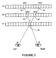
- FIG. 3 the diagram of the light beam movement of the present invention is illustrated.
- a three-panel LCD system is illustrated.
- the display comprises an image presented on a near panel 18 , a mask panel 20 and a distant image panel 22 .
- the relative position of these panels is known and input to the processing block for subsequent display of images.
- mask panel 20 could also be a simpler spatial mask device, such as a diffuser.
- left eye 36 sees a portion 28 on panel 18 of the calculated image sent to that panel. Since the panels are transmissive in nature, left eye 36 also sees a portion 26 of the calculated image displayed on the mask LCD panel 20 . Additionally, and again due to the transmissivity of each LCD panel, left eye 36 also sees a portion 24 of the calculated image which is displayed on a distant LCD panel 22 . In this manner, desired portions of the calculated images are those that are seen by the left eye of the viewer
- right eye 34 sees the same portion 28 of the calculated image on the near panel 18 , as well as sees a portion 30 of the calculated image displayed on the mask panel 20 , as well as a portion 32 of the calculated image on distant panel 22 .
- These portions of the calculated images are those that are to be seen by the right eye of the viewer.
- the memory unit 12 processing block 14 , and LCD control and luminous control 16 regulate the luminous radiation emanating from the distant screen 22 and the transmissivity of the mask 20 and near screen 18 .
- Information concerning multiple discreet two dimensional (2-D) images i.e., multiple calculated images
- Information about positions of the right and left eyes of the viewer are adjusted by the processor block 14 .
- Signals corresponding to the transmission of a portion 28 of near screen 18 , the transmissivity of mask 20 corresponding to the left and right eye respectively ( 26 , 30 ) and the distant screen 22 corresponding to the luminous radiation of those portions of the image of the left and right eye respectively ( 24 , 32 ) are input to the processing block following the set program.
- signals from the cells of all screens that are directed toward the right and left eye of each viewer are then identified.
- signals from cell 28 , 26 , and 24 are all directed toward the left eye of the viewer 36 and signals from block 28 , 30 , and 32 are directed the right eye of the viewer 34 .
- Each of these left and right eye signals is summed 38 to create a value for the right eye 42 and the left eye 40 .
- These signals are then compared in a compare operation 48 to the relevant parts of the image of each aspect and to the relevant areas of the image of the object aspects 44 and 46 .
- the detected signal can vary to some extent. Any errors from the comparison are identified for each cell of each near mask, and distant screen. Each error is then compared to the set threshold signal and, if the error signal exceeds the set threshold signal, the processing block control changes the signals corresponding to the luminous radiation of at least part of the distant screen 22 cells as well changes the transmissivity of at least part of the mask and near cells of the LCD displays.
- the processing block senses that movement and inputs into the memory unit signals corresponding to luminous radiation of the distant screen cells as well as the transmissivity of the mask and near screen cells until the information is modified.
- that view or image is extracted from the database and processed.
- the present invention consists of two transmissive LCD screens, such as illustrated in FIG. 1 .
- the distant and nearest (hereinafter called near) screens 4 and 6 are separated by a gap in which a spatial mask 5 is placed.
- This mask may be pure phase (e.g., lenticular or random screen), amplitude or complex transparency.
- the screens are controlled by the computer 1 .
- the viewing image formed by this system depends upon the displacement of the viewer's eyes to form an autostereographic 3-D image.
- the only problem that must be solved is the calculation of the images (i.e., calculated images) on the distant and near screens for integrating stereo images in the viewer eyes.
- L and R are a left and right pair of stereo images and a viewing-zone for the viewer's eye positions is constant.
- a spatial mask of an amplitude-type will be assumed for simplicity.
- two light beams will come through the arbitrary cell z 28 on the near screen 18 in order to come through the pupils of eyes 34 and 36 .
- These beams will cross mask 20 and distant screen 22 at the points a(z) 26 and c(z) 30 , b(z) 24 and d(z) 32 , respectively.
- the image in the left eye 36 is a summation of:
- N is the intensity of the pixel on the near screen 18
- M is the intensity of the pixel on the mask 20
- D is the intensity of the pixel on the distant screen 22 .
- the images SL and SR are formed on the retinas of the viewer.
- the aim of the calculation is a optimizing of the calculated images on the near and distant screens 18 and 22 to obtain
- ⁇ (x) is a function of the disparity, with the limitation of pixel intensity to 0 ⁇ N ⁇ 255, 0 ⁇ D ⁇ 255 for constant M.
- An artificial Neural Network (NN) was used for this problem solving because of the following specific features:
- the neural network architecture of FIG. 5 was applied to the present problem.
- 50 is a three layer NN.
- the input layer 52 consists of one neuron that spreads the unit excitement to the neurons of the hidden layer 54 .
- the neurons of the hidden layer 54 form three groups that correspond to the near and distant screens and the mask.
- the neurons of the output layer 56 forms two groups that correspond to images SL and SR.
- the number of neurons corresponds to the number of LCD screens pixels.
- Synaptic weights Wij that corresponds to the near and distant screens is an adjusting parameter, and Wij of the mask is a constant.
- Y k F ⁇ ( ⁇ k ⁇ V jk ⁇ X J ) ⁇ - ⁇ output ⁇ ⁇ of ⁇ ⁇ the ⁇ ⁇ NN . ( 7 )
- the output signal in any neuron is a summation of at least one signal from the distant and near screens and the mask.
- the output of the NN (according to (6),(7)), corresponding to the left and right eye of the viewer, is
- the weights Wij have random values.
- the experiments show that an acceptable accuracy was obtained at 10-15 iterations according (10) learning, for some images the extremely low errors can be achieved in 100 iterations.
- the calculations show the strong dependence between the level of errors and the parameters of the optical scheme, such as the shape of the L and R images, the distance between the near and distant screens and the mask, and the viewer eye position.
- the second method involves randomly changing the position of the viewer eye by a small amount during the training of the NN. Both of these methods can be used for enlarging of the area of stereo viewing.
- a typical system to employ the present invention consists of two 15′′ AM LCDs having a resolution of 1024 ⁇ 768 and a computer system on based on an Intel Pentium III-500 MHz processor for stereo image processing.
- the computer emulates the neural network for obtaining the calculated images that must be illuminated on the near and distant screens in order to obtain separated left-right images in predefined areas.
- the neural network emulates the optical scheme of display and the viewer's eye position in order to minimize the errors in the stereo image.
- This technique improves the image quality in comparison with parallax barrier systems due to the total use of the cells of all the screens for the information transmission.
- the present system can also identify the number of the viewers as well as the positions of the right and left eyes of each viewer and perform the above-mentioned procedures to realize the techniques in accordance with the identified eye positions of all the viewers. Such a system makes it possible for several viewers to receive visual information with the perception of the stereoscopic effect simultaneously.
- the signals corresponding to the transmissivity of the near and distant screens cells are input into the memory unit by means of the processing block following the set program.
- the next step is to identify the light signals that can be directed from the cells of all the screens towards the right and left eyes of at least one viewer. Then compare the identified light signals directed towards each eye to the corresponding areas of the set 2-D stereopair image of the relevant object.
- the error signal is identified between the identified light signal that can be directed towards the relevant eye and the identified relevant area of the stereo picture of the relevant object aspect that the same eye should see.
- Each received error signal is compared to the set threshold signal. If the error signal exceeds the set threshold signal, the mentioned program of the processing block control changes the signals corresponding to the screen cells. The above process is repeated until the error signal becomes lower than the set threshold signal or the set time period is up.
- the present invention can be used for multi-viewing display emulation. It has been shown that the number of aspects depends upon the information capacity of the image, such that present experiments allow up to 20 viewing zone images.
- system of the present invention may also be used with multiple viewers observing imagery simultaneously.
- the system simply recognizes the individual viewers'positions (or sets specific viewing zones) and stages images appropriate for the multiple viewers.
- a viewer position signal is input into the system.
- the algorithms used to determine SL and SR use variables for the optical geometry, and the viewer position signal is used to determine those variables. Also, the viewer position signal is used to determine which stereopair to display, based on the optical geometry calculation.
- Numerous known technologies can be used for generating the viewer position signal, including known head/eye tracking systems employed for virtual reality (VR) applications, such as, but not limited to, viewer mounted RF sensors, triangulated IR and ultrasound systems, and camera-based machine vision using video analysis of image data.
- VR virtual reality
Abstract
Description


Claims (20)
Priority Applications (9)
| Application Number | Priority Date | Filing Date | Title |
|---|---|---|---|
| US09/977,462 US6717728B2 (en) | 1999-12-08 | 2001-10-15 | System and method for visualization of stereo and multi aspect images |
| CNA028251008A CN1656420A (en) | 2001-10-15 | 2002-10-15 | System and method for visualization of stereo and multi aspect images |
| KR10-2004-7005527A KR20040071124A (en) | 2001-10-15 | 2002-10-15 | System and method for visualization of stereo and multi aspect images |
| JP2003544527A JP2005509901A (en) | 2001-10-15 | 2002-10-15 | Stereo multi-aspect image visualization system and visualization method |
| EP02795515A EP1444548A4 (en) | 2001-10-15 | 2002-10-15 | System and method for visualization of stereo and multi aspect images |
| PCT/US2002/032620 WO2003042757A1 (en) | 2001-10-15 | 2002-10-15 | System and method for visualization of stereo and multi aspect images |
| US10/751,654 US6985290B2 (en) | 1999-12-08 | 2004-01-06 | Visualization of three dimensional images and multi aspect imaging |
| US10/820,158 US7224526B2 (en) | 1999-12-08 | 2004-04-08 | Three-dimensional free space image projection employing Fresnel lenses |
| US10/945,425 US7342721B2 (en) | 1999-12-08 | 2004-09-21 | Composite dual LCD panel display suitable for three dimensional imaging |
Applications Claiming Priority (2)
| Application Number | Priority Date | Filing Date | Title |
|---|---|---|---|
| US45682699A | 1999-12-08 | 1999-12-08 | |
| US09/977,462 US6717728B2 (en) | 1999-12-08 | 2001-10-15 | System and method for visualization of stereo and multi aspect images |
Related Parent Applications (1)
| Application Number | Title | Priority Date | Filing Date |
|---|---|---|---|
| US45682699A Continuation-In-Part | 1999-12-08 | 1999-12-08 |
Related Child Applications (1)
| Application Number | Title | Priority Date | Filing Date |
|---|---|---|---|
| US10/751,654 Continuation-In-Part US6985290B2 (en) | 1999-12-08 | 2004-01-06 | Visualization of three dimensional images and multi aspect imaging |
Publications (2)
| Publication Number | Publication Date |
|---|---|
| US20020036648A1 US20020036648A1 (en) | 2002-03-28 |
| US6717728B2 true US6717728B2 (en) | 2004-04-06 |
Family
ID=25525147
Family Applications (1)
| Application Number | Title | Priority Date | Filing Date |
|---|---|---|---|
| US09/977,462 Expired - Lifetime US6717728B2 (en) | 1999-12-08 | 2001-10-15 | System and method for visualization of stereo and multi aspect images |
Country Status (6)
| Country | Link |
|---|---|
| US (1) | US6717728B2 (en) |
| EP (1) | EP1444548A4 (en) |
| JP (1) | JP2005509901A (en) |
| KR (1) | KR20040071124A (en) |
| CN (1) | CN1656420A (en) |
| WO (1) | WO2003042757A1 (en) |
Cited By (73)
| Publication number | Priority date | Publication date | Assignee | Title |
|---|---|---|---|---|
| US20040029636A1 (en) * | 2002-08-06 | 2004-02-12 | William Wells | Gaming device having a three dimensional display device |
| US20050059487A1 (en) * | 2003-09-12 | 2005-03-17 | Wilder Richard L. | Three-dimensional autostereoscopic image display for a gaming apparatus |
| US20050153772A1 (en) * | 2004-01-12 | 2005-07-14 | Griswold Chauncey W. | Method and apparatus for using a light valve to reduce the visibility of an object within a gaming apparatus |
| US20060125745A1 (en) * | 2002-06-25 | 2006-06-15 | Evanicky Daniel E | Enhanced viewing experience of a display through localised dynamic control of background lighting level |
| US20060203338A1 (en) * | 2005-03-12 | 2006-09-14 | Polaris Sensor Technologies, Inc. | System and method for dual stacked panel display |
| US20070035830A1 (en) * | 2005-07-11 | 2007-02-15 | Neurok Optics Llc | Two-panel liquid crystal system with circular polarization and polarizer glasses suitable for three dimensional imaging |
| US20070060390A1 (en) * | 2005-09-13 | 2007-03-15 | Igt | Gaming machine with scanning 3-D display system |
| US20070155469A1 (en) * | 2003-10-20 | 2007-07-05 | Sam Johnson | Automatic funding of paragames on electronic gaming platform |
| US20070243934A1 (en) * | 2006-04-13 | 2007-10-18 | Igt | Remote content management and resource sharing on a gaming machine and method of implementing same |
| US20080020841A1 (en) * | 2002-08-06 | 2008-01-24 | Igt | Gaming machine with layered displays |
| US20080020816A1 (en) * | 2004-01-12 | 2008-01-24 | Igt | Multiple-state display for a gaming apparatus |
| US20080113775A1 (en) * | 2006-11-13 | 2008-05-15 | Igt | Three-dimensional paylines for gaming machines |
| US20080113745A1 (en) * | 2006-11-13 | 2008-05-15 | Igt | Separable game graphics on a gaming machine |
| US20080113756A1 (en) * | 2006-11-13 | 2008-05-15 | Igt | Presentation of wheels on gaming machines having multi-layer displays |
| US20080125219A1 (en) * | 2006-04-13 | 2008-05-29 | Igt | Multi-layer display 3D server based portals |
| US20080143895A1 (en) * | 2006-12-15 | 2008-06-19 | Thomas Peterka | Dynamic parallax barrier autosteroscopic display system and method |
| US20080284792A1 (en) * | 2007-05-18 | 2008-11-20 | Gareth Paul Bell | Method and system for improving display quality of a multi-component display |
| US20090061984A1 (en) * | 2007-08-31 | 2009-03-05 | Igt | Reel symbol resizing for reel based gaming machines |
| US20090059173A1 (en) * | 2007-08-28 | 2009-03-05 | Azor Frank C | Methods and systems for projecting images |
| US20090059103A1 (en) * | 2007-08-28 | 2009-03-05 | Azor Frank C | Methods and systems for image processing and display |
| US20090082083A1 (en) * | 2007-09-21 | 2009-03-26 | Igt | Reel blur for gaming machines having simulated rotating reels |
| US20090079667A1 (en) * | 2007-09-20 | 2009-03-26 | Igt | Auto-blanking screen for devices having multi-layer displays |
| US20090098943A1 (en) * | 2006-11-10 | 2009-04-16 | Igt | Gaming Machine with Externally Controlled Content Display |
| US20090104989A1 (en) * | 2007-10-23 | 2009-04-23 | Igt | Separable backlighting system |
| US20090104954A1 (en) * | 2006-04-13 | 2009-04-23 | Igt | Methods and systems for tracking an event of an externally controlled interface |
| US20090111577A1 (en) * | 2007-10-29 | 2009-04-30 | Igt | Gaming system having display device with changeable wheel |
| US20090111578A1 (en) * | 2004-11-05 | 2009-04-30 | Igt | Single source visual image display distribution on a gaming machine |
| US20090124383A1 (en) * | 2007-11-09 | 2009-05-14 | Igt | Apparatus for use with interactive table games and methods of use |
| US20090156303A1 (en) * | 2006-11-10 | 2009-06-18 | Igt | Bonusing Architectures in a Gaming Environment |
| US20090213141A1 (en) * | 2005-10-05 | 2009-08-27 | Puredepth Limited | Method of manipulating visibility of images on a volumetric display |
| US20100105454A1 (en) * | 2006-04-13 | 2010-04-29 | Igt | Methods and systems for interfacing with a third-party application |
| US20100149176A1 (en) * | 2008-12-16 | 2010-06-17 | Chunghwa Picture Tubes, Ltd. | Depth-fused 3d display, driving method thereof and driving circuit thereof |
| US20100156922A1 (en) * | 2001-11-09 | 2010-06-24 | Pure Depth Limited | Rendering of an image using a multi-component display |
| US20100289819A1 (en) * | 2009-05-14 | 2010-11-18 | Pure Depth Limited | Image manipulation |
| US20110007089A1 (en) * | 2009-07-07 | 2011-01-13 | Pure Depth Limited | Method and system of processing images for improved display |
| US20110051091A1 (en) * | 2007-10-16 | 2011-03-03 | Xuefeng Song | Display device and display method |
| US8004515B1 (en) * | 2005-03-15 | 2011-08-23 | Nvidia Corporation | Stereoscopic vertex shader override |
| US8146277B2 (en) | 2002-09-20 | 2012-04-03 | Puredepth Limited | Multi-view display |
| US8154473B2 (en) | 2003-05-16 | 2012-04-10 | Pure Depth Limited | Display control system |
| US8192281B2 (en) | 2006-11-13 | 2012-06-05 | Igt | Simulated reel imperfections |
| US8199068B2 (en) | 2006-11-13 | 2012-06-12 | Igt | Single plane spanning mode across independently driven displays |
| US8298081B1 (en) | 2011-06-16 | 2012-10-30 | Igt | Gaming system, gaming device and method for providing multiple display event indicators |
| US8357033B2 (en) | 2006-11-13 | 2013-01-22 | Igt | Realistic video reels |
| US8360847B2 (en) | 2006-11-13 | 2013-01-29 | Igt | Multimedia emulation of physical reel hardware in processor-based gaming machines |
| US20130027773A1 (en) * | 2010-04-06 | 2013-01-31 | JVC Kenwood Corporation | 3d image display optical member and 3d image display device |
| US20130093752A1 (en) * | 2011-10-13 | 2013-04-18 | Sharp Laboratories Of America, Inc. | Viewer reactive auto stereoscopic display |
| US8425316B2 (en) | 2010-08-03 | 2013-04-23 | Igt | Methods and systems for improving play of a bonus game on a gaming machine and improving security within a gaming establishment |
| US8605114B2 (en) | 2012-02-17 | 2013-12-10 | Igt | Gaming system having reduced appearance of parallax artifacts on display devices including multiple display screens |
| US8715058B2 (en) | 2002-08-06 | 2014-05-06 | Igt | Reel and video combination machine |
| US8777737B2 (en) | 2006-04-13 | 2014-07-15 | Igt | Method and apparatus for integrating remotely-hosted and locally rendered content on a gaming device |
| US9028329B2 (en) | 2006-04-13 | 2015-05-12 | Igt | Integrating remotely-hosted and locally rendered content on a gaming device |
| US9129469B2 (en) | 2012-09-11 | 2015-09-08 | Igt | Player driven game download to a gaming machine |
| US9265458B2 (en) | 2012-12-04 | 2016-02-23 | Sync-Think, Inc. | Application of smooth pursuit cognitive testing paradigms to clinical drug development |
| US9292996B2 (en) | 2006-12-19 | 2016-03-22 | Igt | Distributed side wagering methods and systems |
| US9380976B2 (en) | 2013-03-11 | 2016-07-05 | Sync-Think, Inc. | Optical neuroinformatics |
| US9401065B2 (en) | 2011-09-30 | 2016-07-26 | Igt | System and method for remote rendering of content on an electronic gaming machine |
| US9564004B2 (en) | 2003-10-20 | 2017-02-07 | Igt | Closed-loop system for providing additional event participation to electronic video game customers |
| US9566500B2 (en) | 2013-07-22 | 2017-02-14 | Igt | Gaming table system permitting play of a shared player hand by multiple players |
| US9595159B2 (en) | 2013-10-01 | 2017-03-14 | Igt | System and method for multi-game, multi-play of live dealer games |
| US9613491B2 (en) | 2004-12-16 | 2017-04-04 | Igt | Video gaming device having a system and method for completing wagers and purchases during the cash out process |
| US9659433B2 (en) | 2005-01-24 | 2017-05-23 | Igt | System and method for providing remote wagering games in a live table game system |
| US9666024B2 (en) | 2013-09-03 | 2017-05-30 | Igt | Remote live table gaming terminals and systems |
| US9710995B2 (en) | 2005-01-24 | 2017-07-18 | Igt | Methods and systems for playing Sic Bo jackpot |
| US9824536B2 (en) | 2011-09-30 | 2017-11-21 | Igt | Gaming system, gaming device and method for utilizing mobile devices at a gaming establishment |
| US9916735B2 (en) | 2015-07-22 | 2018-03-13 | Igt | Remote gaming cash voucher printing system |
| US9940777B2 (en) | 2005-01-24 | 2018-04-10 | Igt | Betting terminal and system |
| US9940778B2 (en) | 2005-01-24 | 2018-04-10 | Igt | System for monitoring and playing a plurality of live casino table games |
| US10026255B2 (en) | 2006-04-13 | 2018-07-17 | Igt | Presentation of remotely-hosted and locally rendered content for gaming systems |
| US10055930B2 (en) | 2015-08-11 | 2018-08-21 | Igt | Gaming system and method for placing and redeeming sports bets |
| US10147279B2 (en) | 2005-08-05 | 2018-12-04 | Igt | Methods and systems for playing baccarat jackpot with an option for insurance betting |
| US10198893B2 (en) | 2005-01-24 | 2019-02-05 | Igt | Methods and systems for playing baccarat jackpot |
| US10198898B2 (en) | 2005-01-24 | 2019-02-05 | Igt | Gaming center allowing switching between games based upon historical results |
| US10702763B2 (en) | 2005-01-24 | 2020-07-07 | Igt | Methods and systems for playing baccarat jackpot |
Families Citing this family (21)
| Publication number | Priority date | Publication date | Assignee | Title |
|---|---|---|---|---|
| US7342721B2 (en) * | 1999-12-08 | 2008-03-11 | Iz3D Llc | Composite dual LCD panel display suitable for three dimensional imaging |
| US7708640B2 (en) * | 2002-02-15 | 2010-05-04 | Wms Gaming Inc. | Gaming machine having a persistence-of-vision display |
| JP2004081475A (en) * | 2002-06-25 | 2004-03-18 | Aruze Corp | Game machine |
| US8118674B2 (en) * | 2003-03-27 | 2012-02-21 | Wms Gaming Inc. | Gaming machine having a 3D display |
| US20060058100A1 (en) * | 2004-09-14 | 2006-03-16 | Pacey Larry J | Wagering game with 3D rendering of a mechanical device |
| CA2649411C (en) * | 2006-04-19 | 2019-02-12 | Setred As | Bandwidth improvement for 3d display |
| US20070250868A1 (en) * | 2006-04-20 | 2007-10-25 | Matsushita Electric Industrial Co., Ltd. | Display apparatus and display method |
| KR101432567B1 (en) | 2007-04-19 | 2014-08-21 | 엘지디스플레이 주식회사 | Liquid crystal display device |
| WO2009095862A1 (en) * | 2008-02-01 | 2009-08-06 | Koninklijke Philips Electronics N.V. | Autostereoscopic display device |
| DE102010009737A1 (en) * | 2010-03-01 | 2011-09-01 | Institut für Rundfunktechnik GmbH | Method and arrangement for reproducing 3D image content |
| US8760396B2 (en) * | 2010-06-11 | 2014-06-24 | Lg Display Co., Ltd. | Stereoscopic image display device |
| JP5408099B2 (en) | 2010-10-07 | 2014-02-05 | 株式会社Jvcケンウッド | Autostereoscopic display device |
| BR112013014285A2 (en) * | 2010-12-29 | 2016-09-20 | Thomson Licensing | method and apparatus for providing multi-view system monovision |
| CN102636893A (en) * | 2011-02-09 | 2012-08-15 | 瀚宇彩晶股份有限公司 | Three-dimensional display, barrier device and driving method of three-dimensional display, barrier device |
| JP5603370B2 (en) * | 2011-05-16 | 2014-10-08 | 富士フイルム株式会社 | Parallax image display device, parallax image generation method, and parallax image print |
| US9674510B2 (en) * | 2012-11-21 | 2017-06-06 | Elwha Llc | Pulsed projection system for 3D video |
| WO2016121233A1 (en) | 2015-01-30 | 2016-08-04 | 三菱電機株式会社 | Image processing apparatus, image displaying apparatus, and image processing method |
| KR20180062647A (en) * | 2016-12-01 | 2018-06-11 | 삼성전자주식회사 | Metohd and apparatus for eye detection using depth information |
| CN106600583B (en) * | 2016-12-07 | 2019-11-01 | 西安电子科技大学 | Parallax picture capturing method based on end-to-end neural network |
| WO2019017972A1 (en) * | 2017-07-21 | 2019-01-24 | Hewlett-Packard Development Company, L.P. | Recording and display of light fields |
| US10818398B2 (en) * | 2018-07-27 | 2020-10-27 | University Of Miami | System and method for AI-based eye condition determinations |
Citations (42)
| Publication number | Priority date | Publication date | Assignee | Title |
|---|---|---|---|---|
| US3915548A (en) | 1973-04-30 | 1975-10-28 | Hughes Aircraft Co | Holographic lens and liquid crystal image source for head-up display |
| US3975081A (en) | 1972-10-04 | 1976-08-17 | Matsushita Electric Industrial Co., Ltd. | Signal recording system |
| US4717949A (en) | 1986-03-07 | 1988-01-05 | Dimension Technologies, Inc. | Autostereoscopic display with illuminating lines and light valve |
| US4989954A (en) | 1987-10-09 | 1991-02-05 | Matsushita Electric Industrial Co., Ltd. | Projection type liquid cyrstal display device |
| US5134516A (en) | 1990-04-03 | 1992-07-28 | Thomson-Csf | Device for the projection of images |
| US5200844A (en) | 1992-05-22 | 1993-04-06 | Kaiser Aerospace & Electronics Corporation | Color head-up display system |
| US5317507A (en) | 1990-11-07 | 1994-05-31 | Gallant Stephen I | Method for document retrieval and for word sense disambiguation using neural networks |
| US5379133A (en) | 1992-06-19 | 1995-01-03 | Atl Corporation | Synthetic aperture based real time holographic imaging |
| US5420718A (en) | 1990-02-02 | 1995-05-30 | De Montfort University | Optical image system with improved resolution |
| US5457574A (en) * | 1993-05-06 | 1995-10-10 | Dimension Technologies Inc. | Autostereoscopic display with high power efficiency |
| US5497189A (en) | 1992-09-30 | 1996-03-05 | Fujitsu Limited | Stereoscopic display apparatus |
| US5523886A (en) * | 1994-01-04 | 1996-06-04 | Sega Of America, Inc. | Stereoscopic/monoscopic video display system |
| US5552840A (en) | 1992-03-13 | 1996-09-03 | Sharp Kabushiki Kaisha | Three dimensional projection display reflecting divided polarized light on to reflective liquid crystal display elements |
| US5589956A (en) | 1992-07-31 | 1996-12-31 | Canon Kabushiki Kaisha | Image display apparatus |
| US5619709A (en) | 1993-09-20 | 1997-04-08 | Hnc, Inc. | System and method of context vector generation and retrieval |
| RU2080978C1 (en) | 1987-07-13 | 1997-06-10 | Юрий Иванович Гуркин | Surface-finishing machine |
| US5640171A (en) * | 1994-09-06 | 1997-06-17 | Olympus Optical Company, Ltd. | Image display system |
| RU2103687C1 (en) | 1995-04-11 | 1998-01-27 | Ставропольский научно-исследовательский противочумный институт | Method of differential diagnosis of brucellosis clinical forms in human |
| US5712732A (en) | 1993-03-03 | 1998-01-27 | Street; Graham Stewart Brandon | Autostereoscopic image display adjustable for observer location and distance |
| US5745197A (en) | 1995-10-20 | 1998-04-28 | The Aerospace Corporation | Three-dimensional real-image volumetric display system and method |
| US5764317A (en) | 1995-06-26 | 1998-06-09 | Physical Optics Corporation | 3-D volume visualization display |
| RU2116704C1 (en) | 1991-12-23 | 1998-07-27 | Олег Кимович Никифоров | Method for generation and viewing stereo image for moving observer and device which implements said method |
| US5790284A (en) | 1993-06-01 | 1998-08-04 | Canon Kabushiki Kaisha | Display apparatus and displaying method for image display producing stereoscopic effect |
| US5805244A (en) | 1995-12-11 | 1998-09-08 | Samsung Aerospace Industries, Ltd. | Liquid crystal projector using a monochromatic liquid crystal display |
| US5812223A (en) | 1995-02-28 | 1998-09-22 | Asahi Kogaku Kogyo Kabushiki Kaisha | Color LCD projector with three color separating polarizing beam splitters |
| US5812186A (en) | 1994-07-25 | 1998-09-22 | Polaroid Corporation | Three-dimensional display method(s) and apparatus |
| US5822117A (en) * | 1996-01-22 | 1998-10-13 | Kleinberger; Paul | Systems for three-dimensional viewing including first and second light polarizing layers |
| US5838494A (en) | 1995-01-19 | 1998-11-17 | Canon Kabushiki Kaisha | Apparatus for displaying image allowing observer to recognize stereoscopic image |
| US5872590A (en) * | 1996-11-11 | 1999-02-16 | Fujitsu Ltd. | Image display apparatus and method for allowing stereoscopic video image to be observed |
| US5883606A (en) | 1995-12-18 | 1999-03-16 | Bell Communications Research, Inc. | Flat virtual displays for virtual reality |
| US5903388A (en) | 1992-06-11 | 1999-05-11 | Sedlmayr Steven R | High efficiency electromagnetic beam projector and systems and method for implementation thereof |
| US5912650A (en) | 1996-10-16 | 1999-06-15 | Kaiser Electro-Optics, Inc. | Dichoptic display utilizing a single display device |
| US5930037A (en) * | 1996-04-30 | 1999-07-27 | Nec Corporation | Stereoscopic display apparatus which prevents inverse stereoscopic vision |
| US5945965A (en) * | 1995-06-29 | 1999-08-31 | Canon Kabushiki Kaisha | Stereoscopic image display method |
| US5976017A (en) * | 1994-02-09 | 1999-11-02 | Terumo Kabushiki Kaisha | Stereoscopic-image game playing apparatus |
| US6023253A (en) | 1993-10-29 | 2000-02-08 | Canon Kabushiki Kaisha | Image displaying apparatus |
| US6134532A (en) | 1997-11-14 | 2000-10-17 | Aptex Software, Inc. | System and method for optimal adaptive matching of users to most relevant entity and information in real-time |
| US6173275B1 (en) | 1993-09-20 | 2001-01-09 | Hnc Software, Inc. | Representation and retrieval of images using context vectors derived from image information elements |
| US6252707B1 (en) * | 1996-01-22 | 2001-06-26 | 3Ality, Inc. | Systems for three-dimensional viewing and projection |
| US6289353B1 (en) | 1997-09-24 | 2001-09-11 | Webmd Corporation | Intelligent query system for automatically indexing in a database and automatically categorizing users |
| US6442465B2 (en) * | 1992-05-05 | 2002-08-27 | Automotive Technologies International, Inc. | Vehicular component control systems and methods |
| US6603442B1 (en) * | 1999-05-28 | 2003-08-05 | Lg. Philips Lcd Co., Ltd. | Stereoscopic image display apparatus |
Family Cites Families (2)
| Publication number | Priority date | Publication date | Assignee | Title |
|---|---|---|---|---|
| RU2158949C1 (en) * | 1999-09-02 | 2000-11-10 | Общество с ограниченной ответственностью "НЕЙРОК" | Method for display of object images |
| WO2001043449A1 (en) * | 1999-12-08 | 2001-06-14 | Neurok, Llc | Volumetric display device |
-
2001
- 2001-10-15 US US09/977,462 patent/US6717728B2/en not_active Expired - Lifetime
-
2002
- 2002-10-15 CN CNA028251008A patent/CN1656420A/en active Pending
- 2002-10-15 EP EP02795515A patent/EP1444548A4/en not_active Withdrawn
- 2002-10-15 WO PCT/US2002/032620 patent/WO2003042757A1/en active Application Filing
- 2002-10-15 KR KR10-2004-7005527A patent/KR20040071124A/en not_active Application Discontinuation
- 2002-10-15 JP JP2003544527A patent/JP2005509901A/en active Pending
Patent Citations (43)
| Publication number | Priority date | Publication date | Assignee | Title |
|---|---|---|---|---|
| US3975081A (en) | 1972-10-04 | 1976-08-17 | Matsushita Electric Industrial Co., Ltd. | Signal recording system |
| US3915548A (en) | 1973-04-30 | 1975-10-28 | Hughes Aircraft Co | Holographic lens and liquid crystal image source for head-up display |
| US4717949A (en) | 1986-03-07 | 1988-01-05 | Dimension Technologies, Inc. | Autostereoscopic display with illuminating lines and light valve |
| RU2080978C1 (en) | 1987-07-13 | 1997-06-10 | Юрий Иванович Гуркин | Surface-finishing machine |
| US4989954A (en) | 1987-10-09 | 1991-02-05 | Matsushita Electric Industrial Co., Ltd. | Projection type liquid cyrstal display device |
| US5420718A (en) | 1990-02-02 | 1995-05-30 | De Montfort University | Optical image system with improved resolution |
| US5134516A (en) | 1990-04-03 | 1992-07-28 | Thomson-Csf | Device for the projection of images |
| US5317507A (en) | 1990-11-07 | 1994-05-31 | Gallant Stephen I | Method for document retrieval and for word sense disambiguation using neural networks |
| RU2116704C1 (en) | 1991-12-23 | 1998-07-27 | Олег Кимович Никифоров | Method for generation and viewing stereo image for moving observer and device which implements said method |
| US5552840A (en) | 1992-03-13 | 1996-09-03 | Sharp Kabushiki Kaisha | Three dimensional projection display reflecting divided polarized light on to reflective liquid crystal display elements |
| US6442465B2 (en) * | 1992-05-05 | 2002-08-27 | Automotive Technologies International, Inc. | Vehicular component control systems and methods |
| US5200844A (en) | 1992-05-22 | 1993-04-06 | Kaiser Aerospace & Electronics Corporation | Color head-up display system |
| US5903388A (en) | 1992-06-11 | 1999-05-11 | Sedlmayr Steven R | High efficiency electromagnetic beam projector and systems and method for implementation thereof |
| US5379133A (en) | 1992-06-19 | 1995-01-03 | Atl Corporation | Synthetic aperture based real time holographic imaging |
| US5589956A (en) | 1992-07-31 | 1996-12-31 | Canon Kabushiki Kaisha | Image display apparatus |
| US5497189A (en) | 1992-09-30 | 1996-03-05 | Fujitsu Limited | Stereoscopic display apparatus |
| US5712732A (en) | 1993-03-03 | 1998-01-27 | Street; Graham Stewart Brandon | Autostereoscopic image display adjustable for observer location and distance |
| US5457574A (en) * | 1993-05-06 | 1995-10-10 | Dimension Technologies Inc. | Autostereoscopic display with high power efficiency |
| US5790284A (en) | 1993-06-01 | 1998-08-04 | Canon Kabushiki Kaisha | Display apparatus and displaying method for image display producing stereoscopic effect |
| US5619709A (en) | 1993-09-20 | 1997-04-08 | Hnc, Inc. | System and method of context vector generation and retrieval |
| US5794178A (en) | 1993-09-20 | 1998-08-11 | Hnc Software, Inc. | Visualization of information using graphical representations of context vector based relationships and attributes |
| US6173275B1 (en) | 1993-09-20 | 2001-01-09 | Hnc Software, Inc. | Representation and retrieval of images using context vectors derived from image information elements |
| US6023253A (en) | 1993-10-29 | 2000-02-08 | Canon Kabushiki Kaisha | Image displaying apparatus |
| US5523886A (en) * | 1994-01-04 | 1996-06-04 | Sega Of America, Inc. | Stereoscopic/monoscopic video display system |
| US5976017A (en) * | 1994-02-09 | 1999-11-02 | Terumo Kabushiki Kaisha | Stereoscopic-image game playing apparatus |
| US5812186A (en) | 1994-07-25 | 1998-09-22 | Polaroid Corporation | Three-dimensional display method(s) and apparatus |
| US5640171A (en) * | 1994-09-06 | 1997-06-17 | Olympus Optical Company, Ltd. | Image display system |
| US5838494A (en) | 1995-01-19 | 1998-11-17 | Canon Kabushiki Kaisha | Apparatus for displaying image allowing observer to recognize stereoscopic image |
| US5812223A (en) | 1995-02-28 | 1998-09-22 | Asahi Kogaku Kogyo Kabushiki Kaisha | Color LCD projector with three color separating polarizing beam splitters |
| RU2103687C1 (en) | 1995-04-11 | 1998-01-27 | Ставропольский научно-исследовательский противочумный институт | Method of differential diagnosis of brucellosis clinical forms in human |
| US5764317A (en) | 1995-06-26 | 1998-06-09 | Physical Optics Corporation | 3-D volume visualization display |
| US5945965A (en) * | 1995-06-29 | 1999-08-31 | Canon Kabushiki Kaisha | Stereoscopic image display method |
| US5745197A (en) | 1995-10-20 | 1998-04-28 | The Aerospace Corporation | Three-dimensional real-image volumetric display system and method |
| US5805244A (en) | 1995-12-11 | 1998-09-08 | Samsung Aerospace Industries, Ltd. | Liquid crystal projector using a monochromatic liquid crystal display |
| US5883606A (en) | 1995-12-18 | 1999-03-16 | Bell Communications Research, Inc. | Flat virtual displays for virtual reality |
| US5822117A (en) * | 1996-01-22 | 1998-10-13 | Kleinberger; Paul | Systems for three-dimensional viewing including first and second light polarizing layers |
| US6252707B1 (en) * | 1996-01-22 | 2001-06-26 | 3Ality, Inc. | Systems for three-dimensional viewing and projection |
| US5930037A (en) * | 1996-04-30 | 1999-07-27 | Nec Corporation | Stereoscopic display apparatus which prevents inverse stereoscopic vision |
| US5912650A (en) | 1996-10-16 | 1999-06-15 | Kaiser Electro-Optics, Inc. | Dichoptic display utilizing a single display device |
| US5872590A (en) * | 1996-11-11 | 1999-02-16 | Fujitsu Ltd. | Image display apparatus and method for allowing stereoscopic video image to be observed |
| US6289353B1 (en) | 1997-09-24 | 2001-09-11 | Webmd Corporation | Intelligent query system for automatically indexing in a database and automatically categorizing users |
| US6134532A (en) | 1997-11-14 | 2000-10-17 | Aptex Software, Inc. | System and method for optimal adaptive matching of users to most relevant entity and information in real-time |
| US6603442B1 (en) * | 1999-05-28 | 2003-08-05 | Lg. Philips Lcd Co., Ltd. | Stereoscopic image display apparatus |
Non-Patent Citations (1)
| Title |
|---|
| Lancaster, F. Wilfrid; Information Retrieval Systems, Characteristics, Testing, and Evaluation. |
Cited By (136)
| Publication number | Priority date | Publication date | Assignee | Title |
|---|---|---|---|---|
| US20100156922A1 (en) * | 2001-11-09 | 2010-06-24 | Pure Depth Limited | Rendering of an image using a multi-component display |
| US20060125745A1 (en) * | 2002-06-25 | 2006-06-15 | Evanicky Daniel E | Enhanced viewing experience of a display through localised dynamic control of background lighting level |
| US8416149B2 (en) | 2002-06-25 | 2013-04-09 | Pure Depth Limited | Enhanced viewing experience of a display through localised dynamic control of background lighting level |
| US20080020841A1 (en) * | 2002-08-06 | 2008-01-24 | Igt | Gaming machine with layered displays |
| US20050255908A1 (en) * | 2002-08-06 | 2005-11-17 | William Wells | Gaming device having a three dimensional display device |
| US7951001B2 (en) | 2002-08-06 | 2011-05-31 | Igt | Gaming device having a three dimensional display device |
| US8715058B2 (en) | 2002-08-06 | 2014-05-06 | Igt | Reel and video combination machine |
| US7841944B2 (en) | 2002-08-06 | 2010-11-30 | Igt | Gaming device having a three dimensional display device |
| US20040029636A1 (en) * | 2002-08-06 | 2004-02-12 | William Wells | Gaming device having a three dimensional display device |
| US20080020839A1 (en) * | 2002-08-06 | 2008-01-24 | Igt | Gaming machine with layered displays |
| US8146277B2 (en) | 2002-09-20 | 2012-04-03 | Puredepth Limited | Multi-view display |
| US9292150B2 (en) | 2003-05-16 | 2016-03-22 | Pure Depth Limited | Display control system |
| US8154473B2 (en) | 2003-05-16 | 2012-04-10 | Pure Depth Limited | Display control system |
| US7857700B2 (en) | 2003-09-12 | 2010-12-28 | Igt | Three-dimensional autostereoscopic image display for a gaming apparatus |
| US20050059487A1 (en) * | 2003-09-12 | 2005-03-17 | Wilder Richard L. | Three-dimensional autostereoscopic image display for a gaming apparatus |
| US9564004B2 (en) | 2003-10-20 | 2017-02-07 | Igt | Closed-loop system for providing additional event participation to electronic video game customers |
| US20070155469A1 (en) * | 2003-10-20 | 2007-07-05 | Sam Johnson | Automatic funding of paragames on electronic gaming platform |
| US20080020816A1 (en) * | 2004-01-12 | 2008-01-24 | Igt | Multiple-state display for a gaming apparatus |
| US20050153772A1 (en) * | 2004-01-12 | 2005-07-14 | Griswold Chauncey W. | Method and apparatus for using a light valve to reduce the visibility of an object within a gaming apparatus |
| US7309284B2 (en) | 2004-01-12 | 2007-12-18 | Igt | Method for using a light valve to reduce the visibility of an object within a gaming apparatus |
| US8118670B2 (en) | 2004-01-12 | 2012-02-21 | Igt | Method and apparatus for using a light valve to reduce the visibility of an object within a gaming apparatus |
| US8303407B2 (en) | 2004-11-05 | 2012-11-06 | Igt | Single source visual image display distribution on a gaming machine |
| US20090111578A1 (en) * | 2004-11-05 | 2009-04-30 | Igt | Single source visual image display distribution on a gaming machine |
| US10275984B2 (en) | 2004-12-16 | 2019-04-30 | Igt | Video gaming device having a system and method for completing wagers |
| US9613491B2 (en) | 2004-12-16 | 2017-04-04 | Igt | Video gaming device having a system and method for completing wagers and purchases during the cash out process |
| US10702763B2 (en) | 2005-01-24 | 2020-07-07 | Igt | Methods and systems for playing baccarat jackpot |
| US10013848B2 (en) | 2005-01-24 | 2018-07-03 | Igt | System and method for providing remote wagering games in a live table game system |
| US10198898B2 (en) | 2005-01-24 | 2019-02-05 | Igt | Gaming center allowing switching between games based upon historical results |
| US10198893B2 (en) | 2005-01-24 | 2019-02-05 | Igt | Methods and systems for playing baccarat jackpot |
| US9940778B2 (en) | 2005-01-24 | 2018-04-10 | Igt | System for monitoring and playing a plurality of live casino table games |
| US9659433B2 (en) | 2005-01-24 | 2017-05-23 | Igt | System and method for providing remote wagering games in a live table game system |
| US9940777B2 (en) | 2005-01-24 | 2018-04-10 | Igt | Betting terminal and system |
| US10204475B2 (en) | 2005-01-24 | 2019-02-12 | Igt | Methods and systems for playing for a jackpot |
| US9710995B2 (en) | 2005-01-24 | 2017-07-18 | Igt | Methods and systems for playing Sic Bo jackpot |
| US10467848B2 (en) | 2005-01-24 | 2019-11-05 | Igt | System for monitoring and playing a plurality of live casino table games |
| US20060203338A1 (en) * | 2005-03-12 | 2006-09-14 | Polaris Sensor Technologies, Inc. | System and method for dual stacked panel display |
| US8004515B1 (en) * | 2005-03-15 | 2011-08-23 | Nvidia Corporation | Stereoscopic vertex shader override |
| US8044879B2 (en) * | 2005-07-11 | 2011-10-25 | Iz3D Llc | Two-panel liquid crystal system with circular polarization and polarizer glasses suitable for three dimensional imaging |
| US20070035830A1 (en) * | 2005-07-11 | 2007-02-15 | Neurok Optics Llc | Two-panel liquid crystal system with circular polarization and polarizer glasses suitable for three dimensional imaging |
| US10147279B2 (en) | 2005-08-05 | 2018-12-04 | Igt | Methods and systems for playing baccarat jackpot with an option for insurance betting |
| US7878910B2 (en) | 2005-09-13 | 2011-02-01 | Igt | Gaming machine with scanning 3-D display system |
| US20070060390A1 (en) * | 2005-09-13 | 2007-03-15 | Igt | Gaming machine with scanning 3-D display system |
| US20090213141A1 (en) * | 2005-10-05 | 2009-08-27 | Puredepth Limited | Method of manipulating visibility of images on a volumetric display |
| US8436873B2 (en) | 2005-10-05 | 2013-05-07 | Pure Depth Limited | Method of manipulating visibility of images on a volumetric display |
| US9685034B2 (en) | 2006-04-13 | 2017-06-20 | Igt | Methods and systems for interfacing with a third-party application |
| US9028329B2 (en) | 2006-04-13 | 2015-05-12 | Igt | Integrating remotely-hosted and locally rendered content on a gaming device |
| US8992304B2 (en) | 2006-04-13 | 2015-03-31 | Igt | Methods and systems for tracking an event of an externally controlled interface |
| US10706660B2 (en) | 2006-04-13 | 2020-07-07 | Igt | Presentation of remotely-hosted and locally rendered content for gaming systems |
| US20070243934A1 (en) * | 2006-04-13 | 2007-10-18 | Igt | Remote content management and resource sharing on a gaming machine and method of implementing same |
| US8784196B2 (en) | 2006-04-13 | 2014-07-22 | Igt | Remote content management and resource sharing on a gaming machine and method of implementing same |
| US10607437B2 (en) | 2006-04-13 | 2020-03-31 | Igt | Remote content management and resource sharing on a gaming machine and method of implementing same |
| US10497204B2 (en) | 2006-04-13 | 2019-12-03 | Igt | Methods and systems for tracking an event of an externally controlled interface |
| US8777737B2 (en) | 2006-04-13 | 2014-07-15 | Igt | Method and apparatus for integrating remotely-hosted and locally rendered content on a gaming device |
| US20100105454A1 (en) * | 2006-04-13 | 2010-04-29 | Igt | Methods and systems for interfacing with a third-party application |
| US9342955B2 (en) | 2006-04-13 | 2016-05-17 | Igt | Methods and systems for tracking an event of an externally controlled interface |
| US20090104954A1 (en) * | 2006-04-13 | 2009-04-23 | Igt | Methods and systems for tracking an event of an externally controlled interface |
| US8968077B2 (en) | 2006-04-13 | 2015-03-03 | Idt | Methods and systems for interfacing with a third-party application |
| US9881453B2 (en) | 2006-04-13 | 2018-01-30 | Igt | Integrating remotely-hosted and locally rendered content on a gaming device |
| US8512139B2 (en) | 2006-04-13 | 2013-08-20 | Igt | Multi-layer display 3D server based portals |
| US9959702B2 (en) | 2006-04-13 | 2018-05-01 | Igt | Remote content management and resource sharing on a gaming machine and method of implementing same |
| US10026255B2 (en) | 2006-04-13 | 2018-07-17 | Igt | Presentation of remotely-hosted and locally rendered content for gaming systems |
| US10169950B2 (en) | 2006-04-13 | 2019-01-01 | Igt | Remote content management and resource sharing on a gaming machine and method of implementing same |
| US20080125219A1 (en) * | 2006-04-13 | 2008-05-29 | Igt | Multi-layer display 3D server based portals |
| US20090098943A1 (en) * | 2006-11-10 | 2009-04-16 | Igt | Gaming Machine with Externally Controlled Content Display |
| US10229556B2 (en) | 2006-11-10 | 2019-03-12 | Igt | Gaming machine with externally controlled content display |
| US11087592B2 (en) | 2006-11-10 | 2021-08-10 | Igt | Gaming machine with externally controlled content display |
| US10152846B2 (en) | 2006-11-10 | 2018-12-11 | Igt | Bonusing architectures in a gaming environment |
| US20090156303A1 (en) * | 2006-11-10 | 2009-06-18 | Igt | Bonusing Architectures in a Gaming Environment |
| US9311774B2 (en) | 2006-11-10 | 2016-04-12 | Igt | Gaming machine with externally controlled content display |
| US8357033B2 (en) | 2006-11-13 | 2013-01-22 | Igt | Realistic video reels |
| US20080113756A1 (en) * | 2006-11-13 | 2008-05-15 | Igt | Presentation of wheels on gaming machines having multi-layer displays |
| US20080113745A1 (en) * | 2006-11-13 | 2008-05-15 | Igt | Separable game graphics on a gaming machine |
| US20080113775A1 (en) * | 2006-11-13 | 2008-05-15 | Igt | Three-dimensional paylines for gaming machines |
| US8210922B2 (en) | 2006-11-13 | 2012-07-03 | Igt | Separable game graphics on a gaming machine |
| US8727855B2 (en) | 2006-11-13 | 2014-05-20 | Igt | Three-dimensional paylines for gaming machines |
| US8199068B2 (en) | 2006-11-13 | 2012-06-12 | Igt | Single plane spanning mode across independently driven displays |
| US8192281B2 (en) | 2006-11-13 | 2012-06-05 | Igt | Simulated reel imperfections |
| US8142273B2 (en) | 2006-11-13 | 2012-03-27 | Igt | Presentation of wheels on gaming machines having multi-layer displays |
| US8360847B2 (en) | 2006-11-13 | 2013-01-29 | Igt | Multimedia emulation of physical reel hardware in processor-based gaming machines |
| US8248462B2 (en) | 2006-12-15 | 2012-08-21 | The Board Of Trustees Of The University Of Illinois | Dynamic parallax barrier autosteroscopic display system and method |
| US20080143895A1 (en) * | 2006-12-15 | 2008-06-19 | Thomas Peterka | Dynamic parallax barrier autosteroscopic display system and method |
| US9972169B2 (en) | 2006-12-19 | 2018-05-15 | Igt | Distributed side wagering methods and systems |
| US11514753B2 (en) | 2006-12-19 | 2022-11-29 | Igt | Distributed side wagering methods and systems |
| US9292996B2 (en) | 2006-12-19 | 2016-03-22 | Igt | Distributed side wagering methods and systems |
| US20080284792A1 (en) * | 2007-05-18 | 2008-11-20 | Gareth Paul Bell | Method and system for improving display quality of a multi-component display |
| US8432411B2 (en) * | 2007-05-18 | 2013-04-30 | Pure Depth Limited | Method and system for improving display quality of a multi-component display |
| US20090059173A1 (en) * | 2007-08-28 | 2009-03-05 | Azor Frank C | Methods and systems for projecting images |
| US8115698B2 (en) | 2007-08-28 | 2012-02-14 | Dell Products, L.P. | Methods and systems for image processing and display |
| US8506085B2 (en) | 2007-08-28 | 2013-08-13 | Dell Products, L.P. | Methods and systems for projecting images |
| US20090059103A1 (en) * | 2007-08-28 | 2009-03-05 | Azor Frank C | Methods and systems for image processing and display |
| US8616953B2 (en) | 2007-08-31 | 2013-12-31 | Igt | Reel symbol resizing for reel based gaming machines |
| US20090061984A1 (en) * | 2007-08-31 | 2009-03-05 | Igt | Reel symbol resizing for reel based gaming machines |
| US8115700B2 (en) | 2007-09-20 | 2012-02-14 | Igt | Auto-blanking screen for devices having multi-layer displays |
| US20090079667A1 (en) * | 2007-09-20 | 2009-03-26 | Igt | Auto-blanking screen for devices having multi-layer displays |
| US8348746B2 (en) | 2007-09-21 | 2013-01-08 | Igt | Reel blur for gaming machines having simulated rotating reels |
| US8012010B2 (en) | 2007-09-21 | 2011-09-06 | Igt | Reel blur for gaming machines having simulated rotating reels |
| US20090082083A1 (en) * | 2007-09-21 | 2009-03-26 | Igt | Reel blur for gaming machines having simulated rotating reels |
| US8628196B2 (en) * | 2007-10-16 | 2014-01-14 | Ocean Of Peace Scientific Beijing Ltd. | Display device and display method |
| US20110051091A1 (en) * | 2007-10-16 | 2011-03-03 | Xuefeng Song | Display device and display method |
| US20090104989A1 (en) * | 2007-10-23 | 2009-04-23 | Igt | Separable backlighting system |
| US8758144B2 (en) | 2007-10-23 | 2014-06-24 | Igt | Separable backlighting system |
| US8460098B2 (en) | 2007-10-29 | 2013-06-11 | Igt | Gaming system having display device with changeable wheel |
| US8210944B2 (en) | 2007-10-29 | 2012-07-03 | Igt | Gaming system having display device with changeable wheel |
| US20090111577A1 (en) * | 2007-10-29 | 2009-04-30 | Igt | Gaming system having display device with changeable wheel |
| US20090124383A1 (en) * | 2007-11-09 | 2009-05-14 | Igt | Apparatus for use with interactive table games and methods of use |
| US20100149176A1 (en) * | 2008-12-16 | 2010-06-17 | Chunghwa Picture Tubes, Ltd. | Depth-fused 3d display, driving method thereof and driving circuit thereof |
| US9524700B2 (en) | 2009-05-14 | 2016-12-20 | Pure Depth Limited | Method and system for displaying images of various formats on a single display |
| US20100289819A1 (en) * | 2009-05-14 | 2010-11-18 | Pure Depth Limited | Image manipulation |
| US8928682B2 (en) | 2009-07-07 | 2015-01-06 | Pure Depth Limited | Method and system of processing images for improved display |
| US20110007089A1 (en) * | 2009-07-07 | 2011-01-13 | Pure Depth Limited | Method and system of processing images for improved display |
| US9134601B2 (en) * | 2010-04-06 | 2015-09-15 | JVC Kenwood Corporation | 3D image display optical member and 3D image display device |
| US20130027773A1 (en) * | 2010-04-06 | 2013-01-31 | JVC Kenwood Corporation | 3d image display optical member and 3d image display device |
| US8425316B2 (en) | 2010-08-03 | 2013-04-23 | Igt | Methods and systems for improving play of a bonus game on a gaming machine and improving security within a gaming establishment |
| US8298081B1 (en) | 2011-06-16 | 2012-10-30 | Igt | Gaming system, gaming device and method for providing multiple display event indicators |
| US10515513B2 (en) | 2011-09-30 | 2019-12-24 | Igt | Gaming system, gaming device and method for utilizing mobile devices at a gaming establishment |
| US9466173B2 (en) | 2011-09-30 | 2016-10-11 | Igt | System and method for remote rendering of content on an electronic gaming machine |
| US9824536B2 (en) | 2011-09-30 | 2017-11-21 | Igt | Gaming system, gaming device and method for utilizing mobile devices at a gaming establishment |
| US9401065B2 (en) | 2011-09-30 | 2016-07-26 | Igt | System and method for remote rendering of content on an electronic gaming machine |
| US10204481B2 (en) | 2011-09-30 | 2019-02-12 | Igt | System and method for remote rendering of content on an electronic gaming machine |
| US20130093752A1 (en) * | 2011-10-13 | 2013-04-18 | Sharp Laboratories Of America, Inc. | Viewer reactive auto stereoscopic display |
| US8605114B2 (en) | 2012-02-17 | 2013-12-10 | Igt | Gaming system having reduced appearance of parallax artifacts on display devices including multiple display screens |
| US8749582B2 (en) | 2012-02-17 | 2014-06-10 | Igt | Gaming system having reduced appearance of parallax artifacts on display devices including multiple display screens |
| US9569921B2 (en) | 2012-09-11 | 2017-02-14 | Igt | Player driven game download to a gaming machine |
| US9129469B2 (en) | 2012-09-11 | 2015-09-08 | Igt | Player driven game download to a gaming machine |
| US9265458B2 (en) | 2012-12-04 | 2016-02-23 | Sync-Think, Inc. | Application of smooth pursuit cognitive testing paradigms to clinical drug development |
| US9380976B2 (en) | 2013-03-11 | 2016-07-05 | Sync-Think, Inc. | Optical neuroinformatics |
| US9566500B2 (en) | 2013-07-22 | 2017-02-14 | Igt | Gaming table system permitting play of a shared player hand by multiple players |
| US10629025B2 (en) | 2013-07-22 | 2020-04-21 | Igt | Gaming table system permitting play of a shared player hand by multiple players |
| US10438439B2 (en) | 2013-07-22 | 2019-10-08 | Igt | Gaming table system permitting play of a shared player hand by multiple players |
| US10497207B2 (en) | 2013-09-03 | 2019-12-03 | Igt | Remote live table gaming terminals and systems |
| US9666024B2 (en) | 2013-09-03 | 2017-05-30 | Igt | Remote live table gaming terminals and systems |
| US9595159B2 (en) | 2013-10-01 | 2017-03-14 | Igt | System and method for multi-game, multi-play of live dealer games |
| US9734658B2 (en) | 2013-10-01 | 2017-08-15 | Igt | System and method for multi-game, multi-play of live dealer games |
| US9916735B2 (en) | 2015-07-22 | 2018-03-13 | Igt | Remote gaming cash voucher printing system |
| US10055930B2 (en) | 2015-08-11 | 2018-08-21 | Igt | Gaming system and method for placing and redeeming sports bets |
| US11769365B2 (en) | 2015-08-11 | 2023-09-26 | Igt | Gaming system and method for placing and redeeming sports bets |
Also Published As
| Publication number | Publication date |
|---|---|
| KR20040071124A (en) | 2004-08-11 |
| WO2003042757A1 (en) | 2003-05-22 |
| CN1656420A (en) | 2005-08-17 |
| US20020036648A1 (en) | 2002-03-28 |
| JP2005509901A (en) | 2005-04-14 |
| EP1444548A1 (en) | 2004-08-11 |
| EP1444548A4 (en) | 2007-07-04 |
Similar Documents
| Publication | Publication Date | Title |
|---|---|---|
| US6717728B2 (en) | System and method for visualization of stereo and multi aspect images | |
| US6985290B2 (en) | Visualization of three dimensional images and multi aspect imaging | |
| US7224526B2 (en) | Three-dimensional free space image projection employing Fresnel lenses | |
| US7342721B2 (en) | Composite dual LCD panel display suitable for three dimensional imaging | |
| KR100913933B1 (en) | Image display device and image display method | |
| US6353457B2 (en) | Stereoscopic computer graphics image generating apparatus and stereoscopic TV apparatus | |
| KR101675961B1 (en) | Apparatus and Method for Rendering Subpixel Adaptively | |
| US20030122828A1 (en) | Projection of three-dimensional images | |
| KR100754202B1 (en) | 3D image displaying apparatus and method using eye detection information | |
| US20050146788A1 (en) | Software out-of-focus 3D method, system, and apparatus | |
| KR101663672B1 (en) | Wide viewing angle naked eye 3d image display method and display device | |
| KR20040096519A (en) | Three-dimensional image projection employing retro-reflective screens | |
| US20190281280A1 (en) | Parallax Display using Head-Tracking and Light-Field Display | |
| CN107483915B (en) | Three-dimensional image control method and device | |
| US20130342536A1 (en) | Image processing apparatus, method of controlling the same and computer-readable medium | |
| CN115984122A (en) | HUD backlight display system and method | |
| JP2001218231A (en) | Device and method for displaying stereoscopic image | |
| Loukianitsa et al. | Stereodisplay with neural network image processing | |
| CN114967170A (en) | Display processing method and device based on flexible naked-eye three-dimensional display equipment | |
| Putilin et al. | Stereodisplay with neural network image processing | |
| WO2001043449A1 (en) | Volumetric display device | |
| KR20180013607A (en) | Apparatus and method for glass-free hologram display without flipping images | |
| KARAJEH | Intermediate view reconstruction for multiscopic 3D display | |
| CN115695771A (en) | Display device and display method thereof | |
| JP3425416B2 (en) | Apparatus and method for displaying stereoscopic image |
Legal Events
| Date | Code | Title | Description |
|---|---|---|---|
| AS | Assignment |
Owner name: NEUROK LLC, VIRGINIA Free format text: ASSIGNMENT OF ASSIGNORS INTEREST;ASSIGNOR:PUTILIN, ANDREY N.;REEL/FRAME:013710/0922 Effective date: 20021215 |
|
| STCF | Information on status: patent grant |
Free format text: PATENTED CASE |
|
| AS | Assignment |
Owner name: NEUROK LLC, VIRGINIA Free format text: ASSIGNMENT OF ASSIGNORS INTEREST;ASSIGNOR:LUKYANITSA, ANDREW A.;REEL/FRAME:015509/0695 Effective date: 20040520 |
|
| CC | Certificate of correction | ||
| CC | Certificate of correction | ||
| AS | Assignment |
Owner name: IZ3D LLC, CALIFORNIA Free format text: ASSIGNMENT OF ASSIGNORS INTEREST;ASSIGNOR:NEUROK OPTICS LLC;REEL/FRAME:019235/0089 Effective date: 20070416 Owner name: NEUROK OPTICS LLC, CALIFORNIA Free format text: ASSIGNMENT OF ASSIGNORS INTEREST;ASSIGNOR:NEUROK LLC;REEL/FRAME:019235/0092 Effective date: 20070423 |
|
| FPAY | Fee payment |
Year of fee payment: 4 |
|
| FPAY | Fee payment |
Year of fee payment: 8 |
|
| AS | Assignment |
Owner name: IZ3D, INC., CALIFORNIA Free format text: CHANGE OF NAME;ASSIGNOR:IZ3D LLC;REEL/FRAME:034944/0190 Effective date: 20081112 |
|
| AS | Assignment |
Owner name: IZ3D, INC., CALIFORNIA Free format text: CORRECTIVE ASSIGNMENT TO CORRECT THE PATENT NUMBER 7,352,721 TO 7,342,721 PREVIOUSLY RECORDED ON REEL 034944 FRAME 0190. ASSIGNOR(S) HEREBY CONFIRMS THE ASSIGNMENT;ASSIGNOR:IZ3D LLC;REEL/FRAME:035064/0862 Effective date: 20081112 |
|
| FPAY | Fee payment |
Year of fee payment: 12 |
|
| AS | Assignment |
Owner name: VIRRILLI, JAMES, NEW YORK Free format text: ASSIGNMENT OF ASSIGNORS INTEREST;ASSIGNOR:IZ3D, INC.;REEL/FRAME:042755/0288 Effective date: 20170612 |