US6711501B2 - Vehicle navigation system and method for swathing applications - Google Patents
Vehicle navigation system and method for swathing applications Download PDFInfo
- Publication number
- US6711501B2 US6711501B2 US10/396,788 US39678803A US6711501B2 US 6711501 B2 US6711501 B2 US 6711501B2 US 39678803 A US39678803 A US 39678803A US 6711501 B2 US6711501 B2 US 6711501B2
- Authority
- US
- United States
- Prior art keywords
- vehicle
- swath
- navigation system
- display
- steering
- Prior art date
- Legal status (The legal status is an assumption and is not a legal conclusion. Google has not performed a legal analysis and makes no representation as to the accuracy of the status listed.)
- Expired - Lifetime
Links
- 238000000034 method Methods 0.000 title description 23
- 238000012937 correction Methods 0.000 claims abstract description 42
- 230000007246 mechanism Effects 0.000 claims abstract description 25
- 238000013459 approach Methods 0.000 claims description 9
- 230000004044 response Effects 0.000 claims description 6
- 238000005286 illumination Methods 0.000 claims description 5
- 230000003213 activating effect Effects 0.000 claims 1
- 238000006073 displacement reaction Methods 0.000 claims 1
- 238000005259 measurement Methods 0.000 claims 1
- 230000006870 function Effects 0.000 description 9
- 238000010586 diagram Methods 0.000 description 6
- 238000003491 array Methods 0.000 description 5
- 239000002689 soil Substances 0.000 description 5
- 238000001514 detection method Methods 0.000 description 4
- 238000004364 calculation method Methods 0.000 description 3
- 239000000463 material Substances 0.000 description 3
- 230000004913 activation Effects 0.000 description 2
- 230000008901 benefit Effects 0.000 description 2
- 238000005516 engineering process Methods 0.000 description 2
- 239000012530 fluid Substances 0.000 description 2
- 238000009499 grossing Methods 0.000 description 2
- 239000011159 matrix material Substances 0.000 description 2
- 230000010355 oscillation Effects 0.000 description 2
- 238000005507 spraying Methods 0.000 description 2
- 101000606504 Drosophila melanogaster Tyrosine-protein kinase-like otk Proteins 0.000 description 1
- 238000004891 communication Methods 0.000 description 1
- 230000000295 complement effect Effects 0.000 description 1
- 230000007423 decrease Effects 0.000 description 1
- 230000003292 diminished effect Effects 0.000 description 1
- 239000000428 dust Substances 0.000 description 1
- 230000000694 effects Effects 0.000 description 1
- 239000003337 fertilizer Substances 0.000 description 1
- 239000000446 fuel Substances 0.000 description 1
- 238000003306 harvesting Methods 0.000 description 1
- 239000004009 herbicide Substances 0.000 description 1
- 238000010348 incorporation Methods 0.000 description 1
- 239000002917 insecticide Substances 0.000 description 1
- 230000001788 irregular Effects 0.000 description 1
- 239000004973 liquid crystal related substance Substances 0.000 description 1
- 230000014759 maintenance of location Effects 0.000 description 1
- 238000004519 manufacturing process Methods 0.000 description 1
- 238000000691 measurement method Methods 0.000 description 1
- 239000012528 membrane Substances 0.000 description 1
- 230000000737 periodic effect Effects 0.000 description 1
- 230000008569 process Effects 0.000 description 1
- 238000004162 soil erosion Methods 0.000 description 1
- 230000000007 visual effect Effects 0.000 description 1
Images


Classifications
-
- A—HUMAN NECESSITIES
- A01—AGRICULTURE; FORESTRY; ANIMAL HUSBANDRY; HUNTING; TRAPPING; FISHING
- A01B—SOIL WORKING IN AGRICULTURE OR FORESTRY; PARTS, DETAILS, OR ACCESSORIES OF AGRICULTURAL MACHINES OR IMPLEMENTS, IN GENERAL
- A01B69/00—Steering of agricultural machines or implements; Guiding agricultural machines or implements on a desired track
- A01B69/007—Steering or guiding of agricultural vehicles, e.g. steering of the tractor to keep the plough in the furrow
- A01B69/008—Steering or guiding of agricultural vehicles, e.g. steering of the tractor to keep the plough in the furrow automatic
-
- G—PHYSICS
- G05—CONTROLLING; REGULATING
- G05D—SYSTEMS FOR CONTROLLING OR REGULATING NON-ELECTRIC VARIABLES
- G05D1/00—Control of position, course or altitude of land, water, air, or space vehicles, e.g. automatic pilot
- G05D1/02—Control of position or course in two dimensions
- G05D1/021—Control of position or course in two dimensions specially adapted to land vehicles
- G05D1/0276—Control of position or course in two dimensions specially adapted to land vehicles using signals provided by a source external to the vehicle
- G05D1/0278—Control of position or course in two dimensions specially adapted to land vehicles using signals provided by a source external to the vehicle using satellite positioning signals, e.g. GPS
-
- G—PHYSICS
- G01—MEASURING; TESTING
- G01S—RADIO DIRECTION-FINDING; RADIO NAVIGATION; DETERMINING DISTANCE OR VELOCITY BY USE OF RADIO WAVES; LOCATING OR PRESENCE-DETECTING BY USE OF THE REFLECTION OR RERADIATION OF RADIO WAVES; ANALOGOUS ARRANGEMENTS USING OTHER WAVES
- G01S19/00—Satellite radio beacon positioning systems; Determining position, velocity or attitude using signals transmitted by such systems
- G01S19/01—Satellite radio beacon positioning systems transmitting time-stamped messages, e.g. GPS [Global Positioning System], GLONASS [Global Orbiting Navigation Satellite System] or GALILEO
- G01S19/13—Receivers
- G01S19/14—Receivers specially adapted for specific applications
-
- G—PHYSICS
- G01—MEASURING; TESTING
- G01S—RADIO DIRECTION-FINDING; RADIO NAVIGATION; DETERMINING DISTANCE OR VELOCITY BY USE OF RADIO WAVES; LOCATING OR PRESENCE-DETECTING BY USE OF THE REFLECTION OR RERADIATION OF RADIO WAVES; ANALOGOUS ARRANGEMENTS USING OTHER WAVES
- G01S2205/00—Position-fixing by co-ordinating two or more direction or position line determinations; Position-fixing by co-ordinating two or more distance determinations
- G01S2205/001—Transmission of position information to remote stations
- G01S2205/002—Transmission of position information to remote stations for traffic control, mobile tracking, guidance, surveillance or anti-collision
Definitions
- the present invention relates to the area of agricultural soil working and product application and, more particularly, to a guidance system and display to enable optimally driving swaths in rectangular fields, where parallel swathing is most efficient, and odd shaped fields, where contour swathing is more desirably employed.
- Parallel rows are easier to cultivate than contoured rows, and crop rows are more accurately worked with a narrow implement frame than a wide frame.
- various practices have evolved to avoid gaps in cultivation and overlapping cultivation.
- Earliest practices included marking the edge of a “swath” in which an inert marking material is deposited during one pass from one extremity of the tool frame. On the next pass, the operator would attempt to align an outer extremity of the frame with the previously marked line.
- marking methods involve an additional expense for the marking material and additionally the need to monitor the amount of marking material on-board and replenish when exhausted.
- the present invention provides an improved system for vehicle guidance which is particularly well adapted for use in swathing guidance.
- the present invention includes a position detecting subsystem which provides data defining a currently detected position and a guidance controller which stores the positions detected by the position detecting system and is programmed with routines for generating and storing data defining a reference path and a current path, for calculating current speed and heading and an error in the current position, and for calculating a correction in heading to most expeditiously return the vehicle to the correct current path.
- the present invention repeatedly selects a future intercept point on the desired path and calculates a heading correction to cause the vehicle to move toward the intercept point.
- the cycle of selecting a new intercept point and heading correction is updated often enough to cause the vehicle, if off-track, to “flare” into the desired path. If the vehicle is already on the desired path or on a heading directly toward the intercept point, the method causes the vehicle to remain on the current heading.
- the apparatus includes a display including an arcuate array of steering indicators forming a steering guide along with a linear array of current position indicators to show relative distance and sense, or relative direction, from the desired path.
- a steering correction signal is applied to an automatic steering mechanism on the vehicle to automatically correct or maintain the vehicle on the desired path.
- Another embodiment of the invention uses two straight LED arrays for the steering error and cross track displays and seven-segment or alphanumeric displays for the menu and remote user entry through switches or a keypad.
- the present invention makes use of automatic position detection technologies, preferably including a satellite based global positioning system, such as the United States developed Navstar system, and enhancements thereof. Current versions of differential GPS systems are known to have accuracies within less than one meter. Additionally, other types of position reckoning systems are known, such as those employing various kinds of odometers and rotation encoders, laser devices, and the like, as well as conventional swath marking systems. The present invention contemplates incorporation of such other positioning determining systems within the novel methods described herein.
- Further embodiments of the invention include GPS database management, automatic steering mechanism components retrofit with existing vehicle steering components, previously-covered area detection and area management features.
- the principal objects of the present invention are: to provide an improved system for vehicle guidance; to provide such a system which employs position detecting technique, such as by reception of signals from a satellite based global positioning system; to provide such a system which is particularly well adapted for ground working vehicle, such as agricultural vehicles for soil working, fertilizing, spraying, irrigating, harvesting, and the like; to provide such a system which minimizes gaps and overlaps in crop cultivation; to provide such a system which calculates data ⁇ defining desired paths of the vehicle, monitors the current) position of the vehicle in relation to a desired path, and generates a steering correction signal to maintain the vehicle on the path or to return the vehicle to the path; to provide such a system into which the implement width can be entered to enable calculation of the desired paths for the vehicle to follow; to provide such a system including a display device responsive to the steering correction signal for displaying a needed steering correction for manual steering control; to provide such a system in which the steering correction signal is applied to an automatic steering mechanism; to provide such a system which minimizes
- FIG. 1 is a block diagram illustrating a swathing guidance system which embodies the present invention.
- FIG. 2 is an elevational view of an exemplary swathing guidance system unit by which the present invention is implemented.
- FIG. 3 is a flow diagram illustrating the principal steps of a swathing guidance method which embodies the present invention.
- FIGS. 4, 5 , and 6 are geometric diagrams illustrating application of the methods of the present invention to returning a vehicle to a desired path.
- FIG. 7 is a simplified geometric diagram illustrating a flared return of a vehicle to a desired path by use of the present invention.
- FIG. 8 is an elevational view of an alternative display unit for use in the swathing guidance system of the present invention and incorporating linear arrays of indicators for both a steering guide display and a current position display.
- FIG. 9 is a flowchart of a navigational method of the present invention.
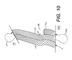
- FIG. 10 is an overhead view of a field showing parts of adjacent swaths in contour mode guidance.
- FIG. 11 is a flowchart of a headlands detection method of the present invention.
- FIG. 12 is a block diagram of an automatic steering assist mechanism of the present invention.
- FIG. 13 is a flowchart of an area measurement method of the present invention.
- the reference numeral 1 generally designates a GPS derived swathing guidance system which embodies the present invention.
- the system 1 generally includes a swathing guidance controller or computer 2 and a position detector device such as a global positioning system receiver 3 .
- the controller 2 stores program routines which receive settings and inputs from switches 4 and causes the display of information on the output display devices 5 .
- the controller 2 cooperates with the GPS receiver 3 to store detected positions and to determine the extent and direction of position or path discrepancy and causes the display of data for corrective movement on the displays 5 .
- FIG. 2 illustrates an exemplary swathing guidance unit 8 which comprises most of the components of the system 1 , including the input switches 4 and the displays 5 .
- the unit includes a base panel 10 on which the input switches 4 and the displays 5 are mounted.
- the illustrated switches 4 include a menu switch 12 , an enter or execute switch 14 , a decrement or down switch 16 , an increment or up switch 18 , a contour mode switch 20 , a parallel mode switch 22 , and a stop guidance switch 24 .
- the displays 5 include a GPS signal quality display 28 , a steering guide display 30 , a current position display 32 , and a menu display 34 .
- the guidance controller 2 may be incorporated into the guidance unit 8 or may be a separate module which is plugged into the unit 8 .
- the GPS receiver 3 may be built into the guidance unit 8 or may be implemented as a separate unit which can be mounted on an agricultural vehicle to optimize the position of an antenna or antennas (not shown) of the receiver 3 . In such a case, the GPS receiver 3 would be connected to the controller 2 by a cable.
- the switches 4 may be formed as membrane switches which have high reliability in agricultural environments which can include high levels of dust and extremes of temperatures.
- the GPS indicators 28 and the indicators of the steering guide display 30 and the current position display 32 may be light emitting diodes (LED's) or fluorescent displays.
- GPS receivers typically must receive signals from at least four GPS satellites in order to calculate the current coarse position.
- the receiver 3 must also receive a signal from a differential GPS transmitter in order to calculate the needed fine position possible with differential GPS technologies.
- the differential correction signals can come from satellite or ground based sources, including C and L band satellites, 300 KHz beacon towers, VHF or UHF radio links, and cell phone or internet based communication systems.
- the GPS signal quality display 28 indicates the quality of GPS signal which is currently being received.
- the illustrated GPS signal quality display 28 includes a “no signal” indicator 38 , a GPS indicator 39 , and a DGPS (differential GPS) indicator 40 , which may differently colored to indicate function. Alternatively, single multi-colored indicator could be employed for the signal quality display 28 .
- the no-signal indicator 38 is activated when an insufficient number of GPS satellites are “visible” to the GPS receiver 3 .
- the GPS indicator 39 indicates coarse GPS functioning, while the DGPS indicator 40 indicates full differential GPS signal acquisition.
- the illustrated steering guide display 30 includes a semicircular or arcuate array of steering guide indicators 42 which, when activated, indicate a steering correction angle to place the guided vehicle on the desired path.
- the steering guide display 30 also includes a line of current heading indicators 43 which are centered on the steering guide 30 and form a reference for the steering correction angle to graphically display a steering or turn correction angle.
- the steering guide display 30 may include angled lines converging at an origin or center of the display 30 to aid a vehicle operator in reading the steering guide display 30 .
- the current heading indicators 43 may be a different color than the remaining steering guide indicators 42 for visual contrast.
- the illustrated current position display 32 is formed by a linear array of position indicators 46 including a centered, current position indicator 47 . At least one of the position indicators 46 is activated, along with the current position indicator 47 , to indicate the relative distance of a guided vehicle from the desired path and the relative direction therefrom, that is, to the left or right of the current position.
- the current position indicator 47 is preferably of a different color than the remaining position indicators.
- the display indicators 38 - 40 , 42 , 43 , 46 , and 47 may be light emitting diodes or fluorescent displays.
- the steering guide 30 and current position display 32 could, alternatively, be implemented as analog meters, graphic displays on a conventional cathode ray tube (CRT) or liquid crystal display (LCD) monitor, or as a proprietary LCD display showing angularly arrayed regions for the steering guide display 30 and linearly arrayed functions for the current position display 32 .
- the steering guide 30 and current position display 32 could, alternatively, be implemented as respective linear arrays of indicators, as shown in an alternative display unit 33 (FIG. 8) which will be described further below.
- the illustrated menu display 34 is preferably a dot matrix LCD display with a capacity for displaying several lines of multiple characters.
- the menu display 34 operates in cooperation with the switches 4 to enable a vehicle operator to select programmed functions of the system 1 , to enter data, such as implement width, and to generally control operation of the system 1 .
- An operating program for the system 1 is stored in memory 50 which is interfaced to the controller 2 .
- the memory 50 may include a combination of read only memory (ROM), non-volatile read/write memory (RAM), and volatile RAM.
- the program menu is entered by operation of the menu switch 12 .
- the down and up switches 16 and 18 are used to step or scroll through the menu selections.
- the enter switch 14 is used to select a function displayed on the menu display 34 .
- the contour and parallel switches 20 and 22 are used to enter respective contour and parallel guidance modes.
- the stop guidance 24 is used to exit a guidance mode.
- the menu display 34 may also be used in cooperation with the steering guide display 30 and current position display 32 to display numeric values of the heading and position information graphically displayed by the steering display 30 and the position display 32 .
- the system 1 is principally described with reference to a steering correction angle which is displayed on the steering guide display 30 .
- a steering correction angle which is calculated by the controller 2 could also be applied to an automatic steering mechanism 52 (FIG. 1 ), such as a mechanism incorporating hydraulic or electromotive elements to steer a vehicle guided by the system 1 .
- Such an automatic steering mechanism 52 controlled by the system 1 of the present invention, would be advantageous in agricultural applications as well as non-agricultural applications. In an agricultural application, such an automatic steering mechanism 52 could be used, even with an operator present, to reduce operator fatigue. Alternatively, some entirely unattended applications are envisioned.
- FIG. 3 illustrates principal steps of a swathing guidance method 60 according to the present invention.
- the method 60 includes storing data defining a desired path for the guided vehicle at 62 .
- the method of characterizing a desired path varies depending on whether a parallel mode or a contour mode has been set by operation of the switches 22 or 20 .
- GPS position readings are taken at a beginning point and an end point of a reference line or path.
- the width of the cultivation implement drawn by the guided vehicle is entered by way of the menu and arrow switches 12 , 16 , and 18 .
- the controller 2 can then calculate a plurality of paths parallel to the reference line, on-the-fly during operation.
- the controller 2 can calculate the paths and store them in the memory 50 .
- Contour mode operation is somewhat different.
- the guided vehicle is driven along a desired contour path with the GPS receiver 3 providing periodic position readings which are stored in the memory 50 .
- the controller 2 can be programmed to detect when a second pass is begun which comes within a selected proximity, such as a multiple of the implement width previously entered. As each pass is driven, data describing the pass is added to the reference data for the next pass.
- Each steering correction loop includes an additional GPS reading at 68 , followed by a comparison step 70 which compares position data from current and previous readings by the controller 2 , a calculation step 72 in which the current speed and heading of the guided vehicle are calculated, and a store step 73 in which the current speed and heading are stored in the memory 50 .
- the controller 2 selects a future intercept point on the stored or projected path at 74 , based on the current:,ground speed of the guided vehicle.
- the distance to the intercept point is selected to quickly lead the guided vehicle back onto the desired path with minimal overshoot. If the intercept point is at too great a distance, the system 1 will not detect mall steering errors. However, if the intercept distance s too small, the steering guide display 30 might become erratic and difficult to read.
- the controller 2 calculates a steering correction angle at 76 to point the guided vehicle toward the intercept point. Unless operation of the stop guidance switch 24 is detected at 78 , the steering correction loop 67 repeats after a timed wait 80 . This timed wait is the time until a new GPS position is received from the GPS receiver 3 , which typically occurs, in the system 1 , every 0.2 seconds. Thus, he GPS receiver 3 and controller 2 preferably have adequate throughput to repeat the steering correction loop 67 lumerous times per second, such as five times per second.
- the steering correction angle calculated at 76 is used to generate a “steering correction signal” with a parameter proportional to the steering correction angle.
- the steering correction angle is scaled to the angular resolution of the steering guide display 30 so that steering indicators 42 and 3 are activated to represent the steering correction angle s accurately as possible.
- the controller 2 calculates a distance of the current position from the nearest position on the desired path as a current position signal and displays a relative distance and relative direction (left or right) to the desired path by activation of a generally proportional number of position indicators 46 and 47 .
- the controller 2 preferably exercises some “update smoothing” techniques to thereby smooth out updates to the indicators of the displays 30 and 32 over time to thereby increase usability of the displays 30 and 32 . If the steering correction signal is applied to an automatic steering mechanism 52 , some update smoothing techniques may also be desirable to avoid erratic operation of the steering mechanism 52 .
- FIGS. 4-6 diagrammatically illustrate use of the system 1 and methods of the present invention to correct the heading of a guided vehicle 85 , represented by an arrow. Relative distances and angles in FIGS. 4-6 are exaggerated for explanatory purposes.
- Line PP represents the desired path and HH the current heading.
- T is the track error or the perpendicular or closest distance of the vehicle 85 from the path PP. It should be noted that although the path PP is shown vertically in FIGS. 4-6, possibly appearing to imply a south to north path as on conventional maps, no such restriction in path direction is intended.
- the controller 2 selects an intercept point IC on the path PP and calculates a steering correction angle S to point the vehicle 85 toward the intercept point IC.
- the steering guide display 30 and position display 32 have respective indicators activated (illustrated as blackened) to display the steering correction angle 5 and the position error T.
- the steering guide display 30 in the system 1 displays the correction angle, not the steering error angle E.
- the steering error angle E is the angular relationship between the current heading HH and the desired path PP.
- the steering correction quantity may be calculated in units other than 5 angular units.
- line X-IC is perpendicular to line HH
- line Y-IC is perpendicular to line PP.
- Lines X-IC and Y-IC are alternative ways of determining a “future crosstrack error”, either by referencing to the current heading HH (X-IC) or to the desired path PP (Y-IC).
- X-IC current heading HH
- Y-IC desired path PP
- both lines X-IC and Y-IC are proportional in length to angle 5 , for a given distance between the vehicle 85 and IC.
- the required steering correction can be calculated in length units instead of angular units.
- FIG. 5 shows the vehicle 85 reoriented toward the intercept point IC in response to the displayed steering correction angle, resulting in no steering correction angle shown on the steering guide display 30 .
- the track or position error in FIG. 5 has diminished to T′.
- FIG. 6 shows the vehicle 85 at a somewhat later time as it has moved along the new heading from FIG. 5, such that the position error has reduced to T/.
- the controller 2 and the method 60 have selected a new intercept point IC′ on path PP and calculated a new steering correction angle S′.
- the steering correction angle S′ is now to the left as viewed and as indicated on the steering guide 30 .
- the current position display 32 indicates that the position error T′′ has been reduced from that detected in FIGS. 4 and 5.
- FIG. 7 graphically illustrates, with some spatial exaggeration, the desired corrective effect of the system 1 and method 60 .
- the selection of the intercept points and calculation of the corresponding steering correction angles leads the vehicle 85 from an error point A along corrective heading path H to a convergence with a generalized path PP at C, with minimal overshoot.
- FIG. 8 illustrates an alternative embodiment of an display unit 33 which includes a steering guide display 30 and a current position display 32 , formed by respective linear arrays of indicators.
- the steering guide display 30 is formed by steering indicators 90 , including a centered current heading indicator 92 .
- the current position display 32 is formed by position indicators 94 , including a centered current position indicator 96 .
- the steering guide display 30 may include a centered index indicator 98 to visually emphasize the center of the display unit 33 .
- the illustrated display unit 33 also includes auxiliary displays 100 which may be seven segment displays, alphanumeric displays, or dot-matrix arrays.
- the displays 30 , 32 , and 100 are interfaced to the guidance controller 2 and receive activation signals therefrom.
- the auxiliary displays 100 are used in cooperation with switches 4 to select menu functions of the controller 2 .
- the steering guide display 30 and the current position display 32 of the display unit 33 function in a manner similar to the corresponding displays 30 and 32 of the unit 8 to graphically display indications of the quantity and sense of corrective steering actions to maintain a vehicle 85 on the desired path PP.
- FIG. 9 is a flowchart showing an example of a methodology that can be utilized with the controller 2 for managing GPS data in conjunction with automatic steering. From start 102 , the method proceeds to start contour mode of operation at 103 and new positions are obtained at 104 by driving the vehicle. GPS data is gathered and downloaded into a master or comprehensive database A at 106 , generally comprising the GPS data (coordinates) for the entire area (e.g., a field) covered in a particular session. At 108 the database A is continuously scanned in the background and a subset representing GPS coordinates close to the current vehicle position, biased in the direction of travel, is generated and maintained as database B. Processor utilization is optimized, and its overhead minimized, by assigning the updating of database B a higher priority than updating database A.
- the database B is updated with sufficient frequency that the vehicle never drives out of the dynamic area defined by the close-proximity GPS coordinates therein.
- Left/right look-ahead or aim points are forward-predicted based on vehicle speed and user input corresponding to the distance of the left and right vehicle extremities from the DGPS antenna at 110 .
- the database C being a subset of A, represents the GPS locations that will be compared to the look-ahead or aim points at 112 .
- the guidance function does not become active (decision box 114 ) until the processor detects look-ahead or aim points corresponding to close-proximity GPS points in the database C. In other words, guidance is normally inactive during a first swath because all of the logged GPS points are typically behind the vehicle.
- Steering guide output is provided at 126 for display as described above or for the automatic steering mechanism 52 .
- Updating the look-ahead points and comparing with database C at 112 is the highest priority. A frequency of 5 Hz is generally satisfactory. Updating the proximity database B at 108 is the second-highest priority.
- the master database A is updated at GPS update rate at 106 . By actively comparing the look-ahead points to the data subset C and relegating the updating of B to a lower priority task, processor “overhead” is reduced. Moreover, the respective look-ahead point associated with the respective vehicle side closest to the previous swath is automatically selected and compared to GPS data in C representing the previous swath edge.
- FIG. 10 shows guidance in contour mode with previous swaths 134 , 135 and a current swath 136 .
- Left and right look-ahead points are defined at 137 , 138 respectively.
- Headlands 139 , 140 are shown at the ends of the swaths.
- the vehicle typically makes 180 degree keyhole-shaped turns, as shown at 141 , 143 .
- FIG. 11 shows a headlands detection method, which starts at 142 , proceeds to commence driving at 144 and loads GPS data into a previous swath area database at 146 .
- the database includes “headlands”, generally representing the turnaround areas for the implement at the ends of the swaths, as shown in FIG. 10 .
- Forward predicted values are determined at 150 and define left/right look-ahead points at 152 for comparison to the previous swath area database at 154 .
- An angle of approach is defined at 155 and represents the angle formed by the current vehicle path with the previously defined area.
- a relatively large (e.g., greater than 30 degrees) angle represents approaching a headland at the end of a swath (affirmative branch from decision box 156 to headlands display 158 .
- a relatively small (e.g., less than 30 degrees) angle of approach indicates a shallow approach to a previous swath, and the negative branch from decision box 156 leads to steering guide output for display and/or automatic steering at 160 .
- the headlands display 158 function illuminates both of the headlands indicator LEDs 162 (FIG. 2 ), which generally indicates that the vehicle has entered a headland (i.e., previously-mapped) area and should turn around. Other responses can be indicated, such as discontinuing spraying or raising an implement, which can be automated in conjunction with the controller/processor 2 . Alternatively, illumination of the headlands indicators 162 can result from the operator driving into a previously-worked area at a sufficiently large angle of approach.
- FIG. 12 is a schematic diagram of the automatic steering mechanism 52 , shown in conjunction with an existing steering control block 164 , which receives inputs from a steering wheel 166 .
- An hydraulic pump 168 provides pressurized hydraulic fluid through the control block 164 to a steering piston-and-cylinder unit 170 , which pivots the steered vehicle wheel 172 .
- the controller 2 is operably connected to an auto-steer control block 174 , which is associated with auto-steer valves 176 whereby hydraulic fluid flow to the piston-and-cylinder unit 170 is controlled by the controller 2 using, for example, the guidance methodology discussed above.
- the auto-steer function can operate in conjunction with manual steering, or independently therefrom.
- the auto steer valves 176 can be on/off (2 position) valves, which provide relatively low pressure inputs to the piston-and-cylinder unit 170 .
- the existing, manual steering controls remain functional and, if necessary, can be used to override the automatic steering mechanism 52 .
- the automatic steering mechanism 52 can operate continuously to maintain the current vehicle swath alongside the previous swath, with the operator manually turning it around at the headlands.
- the auto-steer control block 174 further includes a gyroscope 177 , which can be connected in a feedback loop with the GPS-based auto-steer control circuitry.
- GPS-generated steering assistance can be enhanced with the gyroscope 177 as part of feedback to the output steering signals associated with maintaining a course of the vehicle in cooperation with data output by the GPS position detector.
- FIG. 13 shows a method of determining an area, which starts at 178 and proceeds to select side at 180 , which allows the operator to drive either clockwise or counter-clockwise around the area to be measured.
- the system is placed in contour guidance mode at 182 .
- Memory is cleared at 184 and a start point is logged at 186 .
- Driving commences at 188 , a current position is logged at 190 and compared to the start point at 192 .
- the perimeter is closed at 196 , the area is calculated at 198 and output at 200 to a display as readable text displayed to the operator and/or input to the controller memory. Otherwise, driving around the perimeter continues while current positions are logged.
- the calculated area value remains available as a menu selection by the controller 2 until cleared at 190 . Areas of irregularly-shaped fields can be calculated in the contour guidance mode.
Abstract
Description
Claims (23)
Priority Applications (1)
| Application Number | Priority Date | Filing Date | Title |
|---|---|---|---|
| US10/396,788 US6711501B2 (en) | 2000-12-08 | 2003-03-25 | Vehicle navigation system and method for swathing applications |
Applications Claiming Priority (2)
| Application Number | Priority Date | Filing Date | Title |
|---|---|---|---|
| US09/733,641 US6539303B2 (en) | 2000-12-08 | 2000-12-08 | GPS derived swathing guidance system |
| US10/396,788 US6711501B2 (en) | 2000-12-08 | 2003-03-25 | Vehicle navigation system and method for swathing applications |
Related Parent Applications (1)
| Application Number | Title | Priority Date | Filing Date |
|---|---|---|---|
| US09/733,641 Continuation-In-Part US6539303B2 (en) | 2000-12-08 | 2000-12-08 | GPS derived swathing guidance system |
Publications (2)
| Publication Number | Publication Date |
|---|---|
| US20030187577A1 US20030187577A1 (en) | 2003-10-02 |
| US6711501B2 true US6711501B2 (en) | 2004-03-23 |
Family
ID=46282165
Family Applications (1)
| Application Number | Title | Priority Date | Filing Date |
|---|---|---|---|
| US10/396,788 Expired - Lifetime US6711501B2 (en) | 2000-12-08 | 2003-03-25 | Vehicle navigation system and method for swathing applications |
Country Status (1)
| Country | Link |
|---|---|
| US (1) | US6711501B2 (en) |
Cited By (81)
| Publication number | Priority date | Publication date | Assignee | Title |
|---|---|---|---|---|
| US20040210357A1 (en) * | 2003-04-17 | 2004-10-21 | Mckay Mark D. | Auto-steering apparatus and method |
| US20040212533A1 (en) * | 2003-04-23 | 2004-10-28 | Whitehead Michael L. | Method and system for satellite based phase measurements for relative positioning of fixed or slow moving points in close proximity |
| US20060064222A1 (en) * | 2004-09-21 | 2006-03-23 | Accurtrak Systems Limited | Kit for providing an automatic steering system |
| US20060086295A1 (en) * | 2004-10-21 | 2006-04-27 | Jensen Layton W | Individual row rate control of farm implements to adjust the volume of crop inputs across wide implements in irregularly shaped or contour areas of chemical application, planting or seeding |
| US20060237200A1 (en) * | 2005-04-21 | 2006-10-26 | A.I.L., Inc. | GPS controlled guidance system for farm tractor/implement combination |
| US20070084172A1 (en) * | 2005-10-17 | 2007-04-19 | Richman Kevin S | Guidance indicator system for a cotton harvesting machine |
| US20070129870A1 (en) * | 2004-07-14 | 2007-06-07 | Arthur Lange | Method and system for controlling a mobile machine |
| US20070198185A1 (en) * | 2002-12-11 | 2007-08-23 | Mcclure John A | GNSS control system and method |
| US20070267524A1 (en) * | 2006-05-18 | 2007-11-22 | David Mack | Gps control system and method for irrigation systems |
| US20080060825A1 (en) * | 2005-04-21 | 2008-03-13 | Unruh Marlin W | GPS controlled guidance system for farm tractor/implement combination |
| US20080086249A1 (en) * | 2006-10-05 | 2008-04-10 | Trimble Navigation Limited | Farm apparatus having implement sidehill drift compensation |
| US20080103690A1 (en) * | 2006-10-27 | 2008-05-01 | Dix Peter J | Nudge compensation for curved swath paths |
| US20080103694A1 (en) * | 2006-10-27 | 2008-05-01 | Dix Peter J | Method and apparatus for creating curved swath patterns for farm machinery |
| US20080167770A1 (en) * | 2007-01-05 | 2008-07-10 | Beeline Technologies Pty Ltd | Vehicle control system |
| US20080205494A1 (en) * | 2007-02-27 | 2008-08-28 | Whitehead Michael L | Unbiased code phase discriminator |
| US20080208461A1 (en) * | 2007-02-28 | 2008-08-28 | Imed Gharsalli | Machine with automated steering system |
| US20080228353A1 (en) * | 2007-03-16 | 2008-09-18 | Ronald Lynn Mayfield | System and method of steering for a work vehicle towing a towed implement on lateral slopes |
| US20080269988A1 (en) * | 2003-03-20 | 2008-10-30 | Feller Walter J | Combined gnss gyroscope control system and method |
| US20080269956A1 (en) * | 2007-04-26 | 2008-10-30 | Dix Peter J | Swath finder feature integrated with multipurpose display |
| US20090085815A1 (en) * | 2007-09-27 | 2009-04-02 | Jakab Andrew J | Tightly-coupled pcb gnss circuit and manufacturing method |
| US20090099730A1 (en) * | 2003-03-20 | 2009-04-16 | Mcclure John A | Satellite based vehicle guidance control in straight and contour modes |
| US20090121932A1 (en) * | 2003-03-20 | 2009-05-14 | Whitehead Michael L | Multi-antenna gnss positioning method and system |
| US20090164067A1 (en) * | 2003-03-20 | 2009-06-25 | Whitehead Michael L | Multiple-antenna gnss control system and method |
| US20090204281A1 (en) * | 2008-02-10 | 2009-08-13 | Hemisphere Gps Llc | Visual, gnss and gyro autosteering control |
| US20090251366A1 (en) * | 2008-04-08 | 2009-10-08 | Mcclure John A | Gnss-based mobile communication system and method |
| US20090306835A1 (en) * | 2008-06-06 | 2009-12-10 | Klaus Martin Ellermann | Agricultural vehicle and method of operation therefor |
| US20100023222A1 (en) * | 2008-07-22 | 2010-01-28 | Trimble Navigation Limited | System and Method for Location Based Guidance Controller Configuration |
| US20100018726A1 (en) * | 2008-07-22 | 2010-01-28 | Trimble Navigation Limited | System and Method for Machine Guidance Control |
| US20100019963A1 (en) * | 2006-06-15 | 2010-01-28 | Uti Limited Partnership | Vehicular navigation and positioning system |
| US20100023229A1 (en) * | 2008-07-22 | 2010-01-28 | Trimble Navigation Limited | System and Method for Configuring a Guidance Controller |
| US20100109944A1 (en) * | 2003-03-20 | 2010-05-06 | Whitehead Michael L | Gnss-based tracking of fixed or slow-moving structures |
| US7717356B2 (en) | 2007-06-07 | 2010-05-18 | Scott Petersen | Aerial application dispersal system |
| US20100161179A1 (en) * | 2008-12-22 | 2010-06-24 | Mcclure John A | Integrated dead reckoning and gnss/ins positioning |
| US20100176991A1 (en) * | 2008-12-11 | 2010-07-15 | Webber Mark R | Gnss superband asic with simultaneous multi-frequency down conversion |
| US20100185366A1 (en) * | 2005-07-19 | 2010-07-22 | Heiniger Richard W | Adaptive machine control system and method |
| US20100312428A1 (en) * | 2003-03-20 | 2010-12-09 | Roberge Andre C | Gnss guidance and machine control |
| US20110015831A1 (en) * | 2009-07-17 | 2011-01-20 | Loup Electronics, Inc. | Application rate system for a farm implement |
| US20110015817A1 (en) * | 2009-07-17 | 2011-01-20 | Reeve David R | Optical tracking vehicle control system and method |
| US20110022238A1 (en) * | 2009-07-22 | 2011-01-27 | Pollock Colin J | Gnss control system and method for irrigation and related applications |
| US20110018765A1 (en) * | 2007-10-08 | 2011-01-27 | Whitehead Michael L | Gnss receiver and external storage device system and gnss data processing method |
| US20110025555A1 (en) * | 2009-07-29 | 2011-02-03 | Whitehead Michael L | System and method for augmenting dgnss with internally-generated differential correction |
| US20110054729A1 (en) * | 2004-03-19 | 2011-03-03 | Whitehead Michael L | Multi-antenna gnss control system and method |
| US20110057834A1 (en) * | 2009-09-04 | 2011-03-10 | Miller Steven R | Multi-frequency gnss receiver baseband dsp |
| CN102063822A (en) * | 2011-01-11 | 2011-05-18 | 吉林大学 | Automatic guided vehicle transit system realia |
| US20110172887A1 (en) * | 2009-11-30 | 2011-07-14 | Reeve David R | Vehicle assembly control method for collaborative behavior |
| US20110196565A1 (en) * | 2010-02-09 | 2011-08-11 | Collins Dennis M | Gnss contour guidance path selection |
| US8085196B2 (en) | 2009-03-11 | 2011-12-27 | Hemisphere Gps Llc | Removing biases in dual frequency GNSS receivers using SBAS |
| US8271194B2 (en) | 2004-03-19 | 2012-09-18 | Hemisphere Gps Llc | Method and system using GNSS phase measurements for relative positioning |
| US8359141B1 (en) * | 2005-06-09 | 2013-01-22 | Trimble Navigation Limited | Calibrated farming system |
| US8386129B2 (en) | 2009-01-17 | 2013-02-26 | Hemipshere GPS, LLC | Raster-based contour swathing for guidance and variable-rate chemical application |
| US8548649B2 (en) | 2009-10-19 | 2013-10-01 | Agjunction Llc | GNSS optimized aircraft control system and method |
| US8649930B2 (en) | 2009-09-17 | 2014-02-11 | Agjunction Llc | GNSS integrated multi-sensor control system and method |
| US8825310B2 (en) | 2011-01-05 | 2014-09-02 | Cnh Industrial Canada, Ltd. | Method and apparatus for signaling to an operator of a farm implement that the farm implement is traversing a previously seeded area |
| US8825311B2 (en) | 2011-01-05 | 2014-09-02 | Cnh Industrial Canada, Ltd. | Method and apparatus for signaling to an operator of a farm implement that the farm implement is traversing a seeded area |
| US20140343843A1 (en) * | 2013-05-20 | 2014-11-20 | Physical Enterprises Inc. | Visual Prompts for Route Navigation |
| US9342076B2 (en) | 2010-08-25 | 2016-05-17 | Valmont Industries, Inc. | Adjustable speed irrigation system and method of use |
| US9382003B2 (en) | 2013-03-24 | 2016-07-05 | Bee Robotics Corporation | Aerial farm robot system for crop dusting, planting, fertilizing and other field jobs |
| KR20170083115A (en) * | 2014-11-13 | 2017-07-17 | 아우토리브 디벨롭먼트 아베 | Sensor handover |
| US9750173B2 (en) | 2015-10-27 | 2017-09-05 | Cnh Industrial America Llc | Device and method for guiding agricultural vehicles using modified swath width |
| US9781915B2 (en) | 2013-03-14 | 2017-10-10 | Agjunction Llc | Implement and boom height control system and method |
| US9880562B2 (en) | 2003-03-20 | 2018-01-30 | Agjunction Llc | GNSS and optical guidance and machine control |
| US9945957B2 (en) | 2013-03-14 | 2018-04-17 | Agjunction Llc | Machine control system and method |
| US10042361B2 (en) | 2015-12-07 | 2018-08-07 | Beijing Unistrong Science & Technology Co., Ltd. | System and method for terrestrial vehicle navigation |
| USRE47101E1 (en) | 2003-03-20 | 2018-10-30 | Agjunction Llc | Control for dispensing material from vehicle |
| US10209714B2 (en) | 2016-04-12 | 2019-02-19 | Agjunction Llc | Line acquisition path generation |
| US10239555B2 (en) | 2015-11-19 | 2019-03-26 | Agjunction Llc | Single-mode implement steering |
| US10241215B2 (en) | 2015-11-19 | 2019-03-26 | Agjunction Llc | Sensor alignment calibration |
| US10571576B2 (en) | 2010-11-19 | 2020-02-25 | Agjunction Llc | Portable base station network for local differential GNSS corrections |
| US10579068B2 (en) | 2016-10-03 | 2020-03-03 | Agjunction Llc | Using optical sensors to resolve vehicle heading issues |
| USRE48154E1 (en) | 2012-07-17 | 2020-08-11 | Agjunction Llc | System and method for integrating automatic electrical steering with GNSS guidance |
| US10822017B2 (en) | 2016-10-17 | 2020-11-03 | Agjunction Llc | Integrated auto-steer system for vehicle |
| US10845375B2 (en) | 2016-02-19 | 2020-11-24 | Agjunction Llc | Thermal stabilization of inertial measurement units |
| US10866109B2 (en) | 2017-10-31 | 2020-12-15 | Agjunction Llc | Three-dimensional terrain mapping |
| USRE48527E1 (en) | 2007-01-05 | 2021-04-20 | Agjunction Llc | Optical tracking vehicle control system and method |
| US10986767B2 (en) | 2018-09-14 | 2021-04-27 | Agjunction Llc | Using smart-phones and other hand-held mobile devices in precision agriculture |
| US11091192B2 (en) | 2019-07-31 | 2021-08-17 | Agjunction Llc | Integrated vehicle guidance and steering system |
| US11132003B2 (en) | 2018-09-14 | 2021-09-28 | Agjunction Llc | Integrated GNSS and steering for agricultural guidance systems |
| US11167743B2 (en) | 2018-04-03 | 2021-11-09 | AgJunction, LLC | Automatic pitch mounting compensation in an automatic steering system |
| US11180189B2 (en) | 2015-11-19 | 2021-11-23 | Agjunction Llc | Automated reverse implement parking |
| US11269346B2 (en) | 2017-06-22 | 2022-03-08 | Agjunction Llc | 3-d image system for vehicle control |
| US11960295B2 (en) | 2022-01-28 | 2024-04-16 | Agjunction Llc | 3-D image system for vehicle control |
Families Citing this family (33)
| Publication number | Priority date | Publication date | Assignee | Title |
|---|---|---|---|---|
| US7689354B2 (en) * | 2003-03-20 | 2010-03-30 | Hemisphere Gps Llc | Adaptive guidance system and method |
| US7437230B2 (en) * | 2003-03-20 | 2008-10-14 | Hemisphere Gps Llc | Satellite based vehicle guidance control in straight and contour modes |
| AU2003300514A1 (en) * | 2003-12-01 | 2005-06-24 | Volvo Technology Corporation | Perceptual enhancement displays based on knowledge of head and/or eye and/or gaze position |
| US20060178820A1 (en) * | 2005-02-04 | 2006-08-10 | Novariant, Inc. | System and method for guiding an agricultural vehicle through a recorded template of guide paths |
| US20070032932A1 (en) * | 2005-08-05 | 2007-02-08 | Yeoh Chin H | Method and apparatus for providing a visual indication of a position of a steerable wheel, and components thereof |
| US7596451B2 (en) * | 2006-01-06 | 2009-09-29 | Caterpillar Inc. | Mobile-machine navigation system |
| US9113588B2 (en) * | 2006-12-15 | 2015-08-25 | Deere & Company | Tracking system configured to determine a parameter for use in guiding an implement attached to a work machine |
| US7747370B2 (en) * | 2007-04-03 | 2010-06-29 | Cnh America Llc | Method for creating end of row turns for agricultural vehicles |
| US8209075B2 (en) * | 2007-07-31 | 2012-06-26 | Deere & Company | Method and system for generating end turns |
| US8204654B2 (en) * | 2008-03-20 | 2012-06-19 | Deere & Company | System and method for generation of an inner boundary of a work area |
| US8655536B2 (en) * | 2009-11-16 | 2014-02-18 | Trimble Navigation Limited | Method and system for augmenting a guidance system with a path sensor |
| US20110267220A1 (en) * | 2010-04-30 | 2011-11-03 | John Paul Strachan | Sensor node positioning in a sensor network |
| US8793090B2 (en) | 2010-06-23 | 2014-07-29 | Aisin Aw Co., Ltd. | Track information generating device, track information generating method, and computer-readable storage medium |
| DE102011109491A1 (en) * | 2011-08-04 | 2013-02-07 | GM Global Technology Operations LLC (n. d. Gesetzen des Staates Delaware) | Driving assistance device to support the driving of narrow roads |
| US20130169785A1 (en) * | 2011-12-30 | 2013-07-04 | Agco Corporation | Method of detecting and improving operator situational awareness on agricultural machines |
| US20140288824A1 (en) * | 2013-03-22 | 2014-09-25 | Qualcomm Incorporated | Method and/or system for selective application of direction of travel |
| FR3013495B1 (en) * | 2013-11-15 | 2021-05-07 | Airbus Operations Sas | METHOD AND DEVICE FOR AUTOMATIC GUIDANCE OF A RUNNING AIRCRAFT. |
| US20150149563A1 (en) * | 2013-11-26 | 2015-05-28 | At&T Intellectual Property I, L.P. | Intelligent machine-to-machine (im2m) reserve |
| US9560470B2 (en) * | 2014-05-01 | 2017-01-31 | GM Global Technology Operations LLC | Updating a vehicle head unit with content from a wireless device |
| EP3020868B1 (en) * | 2014-11-14 | 2020-11-04 | Caterpillar Inc. | Machine of a kind comprising a body and an implement movable relative to the body with a system for assisting a user of the machine |
| EP3021178B1 (en) * | 2014-11-14 | 2020-02-19 | Caterpillar Inc. | System using radar apparatus for assisting a user of a machine of a kind comprising a body and an implement |
| CA163371S (en) | 2015-07-08 | 2016-11-25 | The Royal Institution For The Advancement Of Learning/Mcgill University | Steering wheel adapter for an agricultural vehicle vision guidance system |
| US10104827B2 (en) | 2015-07-08 | 2018-10-23 | The Royal Institution For The Advancement Of Learning/Mcgill University | Guidance system and steering control device for an agricultural vehicle |
| US9795074B2 (en) * | 2015-10-27 | 2017-10-24 | Cnh Industrial America Llc | Automatic swath generation device and methods |
| US10152891B2 (en) * | 2016-05-02 | 2018-12-11 | Cnh Industrial America Llc | System for avoiding collisions between autonomous vehicles conducting agricultural operations |
| FR3052139B1 (en) * | 2016-06-03 | 2021-10-08 | Pierre Regnier | BICYCLE AND BIKE HANDLEBAR NAVIGATION PROCESS |
| GB2563262B (en) * | 2017-06-08 | 2020-06-10 | Caterpillar Sarl | Improvements in the stability of work machines |
| EP3811749A4 (en) * | 2018-06-25 | 2023-03-15 | Kubota Corporation | Work vehicle |
| WO2021068177A1 (en) * | 2019-10-11 | 2021-04-15 | 安徽中科智能感知产业技术研究院有限责任公司 | Agricultural machinery operation area calculation method based on positioning drift calculation model |
| US11340092B2 (en) * | 2020-01-29 | 2022-05-24 | Deere & Company | Work vehicle display systems and methods for automatic section control lookahead symbology |
| AR121386A1 (en) | 2020-02-21 | 2022-06-01 | Climate Corp | SIGNALING OF OPERATIONAL DIFFERENCES IN AGRICULTURAL IMPLEMENTS |
| CN115951662A (en) * | 2020-05-21 | 2023-04-11 | 深圳市海柔创新科技有限公司 | Navigation method, navigation device and mobile carrier |
| JP2022025330A (en) * | 2020-07-29 | 2022-02-10 | セイコーエプソン株式会社 | Integrated circuit device, liquid crystal display, electronic apparatus, and movable body |
Citations (3)
| Publication number | Priority date | Publication date | Assignee | Title |
|---|---|---|---|---|
| US5644139A (en) * | 1995-03-02 | 1997-07-01 | Allen; Ross R. | Navigation technique for detecting movement of navigation sensors relative to an object |
| US6389345B2 (en) * | 1999-06-29 | 2002-05-14 | Caterpillar Inc. | Method and apparatus for determining a cross slope of a surface |
| US6539303B2 (en) * | 2000-12-08 | 2003-03-25 | Mcclure John A. | GPS derived swathing guidance system |
-
2003
- 2003-03-25 US US10/396,788 patent/US6711501B2/en not_active Expired - Lifetime
Patent Citations (3)
| Publication number | Priority date | Publication date | Assignee | Title |
|---|---|---|---|---|
| US5644139A (en) * | 1995-03-02 | 1997-07-01 | Allen; Ross R. | Navigation technique for detecting movement of navigation sensors relative to an object |
| US6389345B2 (en) * | 1999-06-29 | 2002-05-14 | Caterpillar Inc. | Method and apparatus for determining a cross slope of a surface |
| US6539303B2 (en) * | 2000-12-08 | 2003-03-25 | Mcclure John A. | GPS derived swathing guidance system |
Cited By (136)
| Publication number | Priority date | Publication date | Assignee | Title |
|---|---|---|---|---|
| US20070198185A1 (en) * | 2002-12-11 | 2007-08-23 | Mcclure John A | GNSS control system and method |
| US7885745B2 (en) | 2002-12-11 | 2011-02-08 | Hemisphere Gps Llc | GNSS control system and method |
| US8594879B2 (en) | 2003-03-20 | 2013-11-26 | Agjunction Llc | GNSS guidance and machine control |
| US8190337B2 (en) | 2003-03-20 | 2012-05-29 | Hemisphere GPS, LLC | Satellite based vehicle guidance control in straight and contour modes |
| US20100109944A1 (en) * | 2003-03-20 | 2010-05-06 | Whitehead Michael L | Gnss-based tracking of fixed or slow-moving structures |
| US8138970B2 (en) | 2003-03-20 | 2012-03-20 | Hemisphere Gps Llc | GNSS-based tracking of fixed or slow-moving structures |
| US10168714B2 (en) | 2003-03-20 | 2019-01-01 | Agjunction Llc | GNSS and optical guidance and machine control |
| US8140223B2 (en) | 2003-03-20 | 2012-03-20 | Hemisphere Gps Llc | Multiple-antenna GNSS control system and method |
| US20090164067A1 (en) * | 2003-03-20 | 2009-06-25 | Whitehead Michael L | Multiple-antenna gnss control system and method |
| US20090121932A1 (en) * | 2003-03-20 | 2009-05-14 | Whitehead Michael L | Multi-antenna gnss positioning method and system |
| USRE47101E1 (en) | 2003-03-20 | 2018-10-30 | Agjunction Llc | Control for dispensing material from vehicle |
| US20090099730A1 (en) * | 2003-03-20 | 2009-04-16 | Mcclure John A | Satellite based vehicle guidance control in straight and contour modes |
| US9886038B2 (en) | 2003-03-20 | 2018-02-06 | Agjunction Llc | GNSS and optical guidance and machine control |
| US9880562B2 (en) | 2003-03-20 | 2018-01-30 | Agjunction Llc | GNSS and optical guidance and machine control |
| US8686900B2 (en) | 2003-03-20 | 2014-04-01 | Hemisphere GNSS, Inc. | Multi-antenna GNSS positioning method and system |
| US20080269988A1 (en) * | 2003-03-20 | 2008-10-30 | Feller Walter J | Combined gnss gyroscope control system and method |
| US20100312428A1 (en) * | 2003-03-20 | 2010-12-09 | Roberge Andre C | Gnss guidance and machine control |
| US8265826B2 (en) | 2003-03-20 | 2012-09-11 | Hemisphere GPS, LLC | Combined GNSS gyroscope control system and method |
| US20040210357A1 (en) * | 2003-04-17 | 2004-10-21 | Mckay Mark D. | Auto-steering apparatus and method |
| US7191061B2 (en) * | 2003-04-17 | 2007-03-13 | Battelle Energy Alliance, Llc | Auto-steering apparatus and method |
| US20040212533A1 (en) * | 2003-04-23 | 2004-10-28 | Whitehead Michael L. | Method and system for satellite based phase measurements for relative positioning of fixed or slow moving points in close proximity |
| US20110054729A1 (en) * | 2004-03-19 | 2011-03-03 | Whitehead Michael L | Multi-antenna gnss control system and method |
| US8583315B2 (en) | 2004-03-19 | 2013-11-12 | Agjunction Llc | Multi-antenna GNSS control system and method |
| US8271194B2 (en) | 2004-03-19 | 2012-09-18 | Hemisphere Gps Llc | Method and system using GNSS phase measurements for relative positioning |
| US20070129870A1 (en) * | 2004-07-14 | 2007-06-07 | Arthur Lange | Method and system for controlling a mobile machine |
| US7263422B2 (en) * | 2004-07-14 | 2007-08-28 | Trimble Navigation Limited | Method and system for controlling a mobile machine |
| US20060064222A1 (en) * | 2004-09-21 | 2006-03-23 | Accurtrak Systems Limited | Kit for providing an automatic steering system |
| US7395769B2 (en) | 2004-10-21 | 2008-07-08 | Jensen Layton W | Individual row rate control of farm implements to adjust the volume of crop inputs across wide implements in irregularly shaped or contour areas of chemical application, planting or seeding |
| US20060086295A1 (en) * | 2004-10-21 | 2006-04-27 | Jensen Layton W | Individual row rate control of farm implements to adjust the volume of crop inputs across wide implements in irregularly shaped or contour areas of chemical application, planting or seeding |
| US7623952B2 (en) | 2005-04-21 | 2009-11-24 | A.I.L., Inc. | GPS controlled guidance system for farm tractor/implement combination |
| US7490678B2 (en) | 2005-04-21 | 2009-02-17 | A.I.L., Inc. | GPS controlled guidance system for farm tractor/implement combination |
| US20080060825A1 (en) * | 2005-04-21 | 2008-03-13 | Unruh Marlin W | GPS controlled guidance system for farm tractor/implement combination |
| US20060237200A1 (en) * | 2005-04-21 | 2006-10-26 | A.I.L., Inc. | GPS controlled guidance system for farm tractor/implement combination |
| US8359141B1 (en) * | 2005-06-09 | 2013-01-22 | Trimble Navigation Limited | Calibrated farming system |
| US8214111B2 (en) * | 2005-07-19 | 2012-07-03 | Hemisphere Gps Llc | Adaptive machine control system and method |
| US20100185366A1 (en) * | 2005-07-19 | 2010-07-22 | Heiniger Richard W | Adaptive machine control system and method |
| US20070084172A1 (en) * | 2005-10-17 | 2007-04-19 | Richman Kevin S | Guidance indicator system for a cotton harvesting machine |
| US20070267524A1 (en) * | 2006-05-18 | 2007-11-22 | David Mack | Gps control system and method for irrigation systems |
| US20100019963A1 (en) * | 2006-06-15 | 2010-01-28 | Uti Limited Partnership | Vehicular navigation and positioning system |
| US20080086249A1 (en) * | 2006-10-05 | 2008-04-10 | Trimble Navigation Limited | Farm apparatus having implement sidehill drift compensation |
| US8489290B1 (en) | 2006-10-05 | 2013-07-16 | Trimble Navigation Limited | Farm sidehill compensation |
| US7844378B2 (en) | 2006-10-05 | 2010-11-30 | Trimble Navigation Limited | Farm apparatus having implement sidehill drift compensation |
| US20080103690A1 (en) * | 2006-10-27 | 2008-05-01 | Dix Peter J | Nudge compensation for curved swath paths |
| US7715979B2 (en) | 2006-10-27 | 2010-05-11 | Cnh America Llc | Nudge compensation for curved swath paths |
| US7689356B2 (en) | 2006-10-27 | 2010-03-30 | Cnh America Llc | Method and apparatus for creating curved swath patterns for farm machinery |
| US20080103694A1 (en) * | 2006-10-27 | 2008-05-01 | Dix Peter J | Method and apparatus for creating curved swath patterns for farm machinery |
| US20080167770A1 (en) * | 2007-01-05 | 2008-07-10 | Beeline Technologies Pty Ltd | Vehicle control system |
| USRE48527E1 (en) | 2007-01-05 | 2021-04-20 | Agjunction Llc | Optical tracking vehicle control system and method |
| WO2008080193A1 (en) * | 2007-01-05 | 2008-07-10 | Hemisphere Gps Llc | A vehicle control system |
| US7835832B2 (en) | 2007-01-05 | 2010-11-16 | Hemisphere Gps Llc | Vehicle control system |
| AU2008203618B2 (en) * | 2007-01-05 | 2013-07-11 | Agjunction Llc | A vehicle control system |
| US20110118938A1 (en) * | 2007-01-05 | 2011-05-19 | Andrew John Macdonald | Vehicle control system |
| US8000381B2 (en) | 2007-02-27 | 2011-08-16 | Hemisphere Gps Llc | Unbiased code phase discriminator |
| US20080205494A1 (en) * | 2007-02-27 | 2008-08-28 | Whitehead Michael L | Unbiased code phase discriminator |
| US20080208461A1 (en) * | 2007-02-28 | 2008-08-28 | Imed Gharsalli | Machine with automated steering system |
| US8060299B2 (en) | 2007-02-28 | 2011-11-15 | Caterpillar Inc. | Machine with automated steering system |
| US8565984B2 (en) * | 2007-03-16 | 2013-10-22 | Deere & Comany | System and method of steering for a work vehicle towing a towed implement on lateral slopes |
| US20080228353A1 (en) * | 2007-03-16 | 2008-09-18 | Ronald Lynn Mayfield | System and method of steering for a work vehicle towing a towed implement on lateral slopes |
| US8145390B2 (en) | 2007-04-26 | 2012-03-27 | Cnh America Llc | Swath finder feature integrated with multipurpose display |
| US20080269956A1 (en) * | 2007-04-26 | 2008-10-30 | Dix Peter J | Swath finder feature integrated with multipurpose display |
| US7717356B2 (en) | 2007-06-07 | 2010-05-18 | Scott Petersen | Aerial application dispersal system |
| US7948769B2 (en) | 2007-09-27 | 2011-05-24 | Hemisphere Gps Llc | Tightly-coupled PCB GNSS circuit and manufacturing method |
| US20090085815A1 (en) * | 2007-09-27 | 2009-04-02 | Jakab Andrew J | Tightly-coupled pcb gnss circuit and manufacturing method |
| US20110018765A1 (en) * | 2007-10-08 | 2011-01-27 | Whitehead Michael L | Gnss receiver and external storage device system and gnss data processing method |
| US8456356B2 (en) | 2007-10-08 | 2013-06-04 | Hemisphere Gnss Inc. | GNSS receiver and external storage device system and GNSS data processing method |
| US9002566B2 (en) | 2008-02-10 | 2015-04-07 | AgJunction, LLC | Visual, GNSS and gyro autosteering control |
| US20090204281A1 (en) * | 2008-02-10 | 2009-08-13 | Hemisphere Gps Llc | Visual, gnss and gyro autosteering control |
| US20090251366A1 (en) * | 2008-04-08 | 2009-10-08 | Mcclure John A | Gnss-based mobile communication system and method |
| US8018376B2 (en) | 2008-04-08 | 2011-09-13 | Hemisphere Gps Llc | GNSS-based mobile communication system and method |
| US20090306835A1 (en) * | 2008-06-06 | 2009-12-10 | Klaus Martin Ellermann | Agricultural vehicle and method of operation therefor |
| US20100023222A1 (en) * | 2008-07-22 | 2010-01-28 | Trimble Navigation Limited | System and Method for Location Based Guidance Controller Configuration |
| US20100018726A1 (en) * | 2008-07-22 | 2010-01-28 | Trimble Navigation Limited | System and Method for Machine Guidance Control |
| US20100023229A1 (en) * | 2008-07-22 | 2010-01-28 | Trimble Navigation Limited | System and Method for Configuring a Guidance Controller |
| US8515626B2 (en) * | 2008-07-22 | 2013-08-20 | Trimble Navigation Limited | System and method for machine guidance control |
| US8401744B2 (en) | 2008-07-22 | 2013-03-19 | Trimble Navigation Limited | System and method for configuring a guidance controller |
| US20100176991A1 (en) * | 2008-12-11 | 2010-07-15 | Webber Mark R | Gnss superband asic with simultaneous multi-frequency down conversion |
| US8217833B2 (en) | 2008-12-11 | 2012-07-10 | Hemisphere Gps Llc | GNSS superband ASIC with simultaneous multi-frequency down conversion |
| US20100161179A1 (en) * | 2008-12-22 | 2010-06-24 | Mcclure John A | Integrated dead reckoning and gnss/ins positioning |
| US8386129B2 (en) | 2009-01-17 | 2013-02-26 | Hemipshere GPS, LLC | Raster-based contour swathing for guidance and variable-rate chemical application |
| USRE48509E1 (en) | 2009-01-17 | 2021-04-13 | Agjunction Llc | Raster-based contour swathing for guidance and variable-rate chemical application |
| USRE47055E1 (en) | 2009-01-17 | 2018-09-25 | Agjunction Llc | Raster-based contour swathing for guidance and variable-rate chemical application |
| US8085196B2 (en) | 2009-03-11 | 2011-12-27 | Hemisphere Gps Llc | Removing biases in dual frequency GNSS receivers using SBAS |
| US20110015817A1 (en) * | 2009-07-17 | 2011-01-20 | Reeve David R | Optical tracking vehicle control system and method |
| US20110015831A1 (en) * | 2009-07-17 | 2011-01-20 | Loup Electronics, Inc. | Application rate system for a farm implement |
| US8311696B2 (en) | 2009-07-17 | 2012-11-13 | Hemisphere Gps Llc | Optical tracking vehicle control system and method |
| US8401704B2 (en) | 2009-07-22 | 2013-03-19 | Hemisphere GPS, LLC | GNSS control system and method for irrigation and related applications |
| US20110022238A1 (en) * | 2009-07-22 | 2011-01-27 | Pollock Colin J | Gnss control system and method for irrigation and related applications |
| US20110025555A1 (en) * | 2009-07-29 | 2011-02-03 | Whitehead Michael L | System and method for augmenting dgnss with internally-generated differential correction |
| US8174437B2 (en) | 2009-07-29 | 2012-05-08 | Hemisphere Gps Llc | System and method for augmenting DGNSS with internally-generated differential correction |
| US20110057834A1 (en) * | 2009-09-04 | 2011-03-10 | Miller Steven R | Multi-frequency gnss receiver baseband dsp |
| US8334804B2 (en) | 2009-09-04 | 2012-12-18 | Hemisphere Gps Llc | Multi-frequency GNSS receiver baseband DSP |
| US8649930B2 (en) | 2009-09-17 | 2014-02-11 | Agjunction Llc | GNSS integrated multi-sensor control system and method |
| USRE47648E1 (en) | 2009-09-17 | 2019-10-15 | Agjunction Llc | Integrated multi-sensor control system and method |
| US8548649B2 (en) | 2009-10-19 | 2013-10-01 | Agjunction Llc | GNSS optimized aircraft control system and method |
| US20110172887A1 (en) * | 2009-11-30 | 2011-07-14 | Reeve David R | Vehicle assembly control method for collaborative behavior |
| US20110196565A1 (en) * | 2010-02-09 | 2011-08-11 | Collins Dennis M | Gnss contour guidance path selection |
| US8583326B2 (en) * | 2010-02-09 | 2013-11-12 | Agjunction Llc | GNSS contour guidance path selection |
| US9342076B2 (en) | 2010-08-25 | 2016-05-17 | Valmont Industries, Inc. | Adjustable speed irrigation system and method of use |
| US10571576B2 (en) | 2010-11-19 | 2020-02-25 | Agjunction Llc | Portable base station network for local differential GNSS corrections |
| US9775281B2 (en) | 2011-01-05 | 2017-10-03 | Cnh Industrial Canada, Ltd. | Sectional control method for use with an agricultural implement |
| US8825311B2 (en) | 2011-01-05 | 2014-09-02 | Cnh Industrial Canada, Ltd. | Method and apparatus for signaling to an operator of a farm implement that the farm implement is traversing a seeded area |
| US8825310B2 (en) | 2011-01-05 | 2014-09-02 | Cnh Industrial Canada, Ltd. | Method and apparatus for signaling to an operator of a farm implement that the farm implement is traversing a previously seeded area |
| US10051784B2 (en) | 2011-01-05 | 2018-08-21 | Cnh Industrial Canada, Ltd. | Sectional control method for use with an agricultural implement |
| CN102063822A (en) * | 2011-01-11 | 2011-05-18 | 吉林大学 | Automatic guided vehicle transit system realia |
| CN102063822B (en) * | 2011-01-11 | 2012-06-27 | 吉林大学 | Automatic guided vehicle transit system realia |
| USRE48154E1 (en) | 2012-07-17 | 2020-08-11 | Agjunction Llc | System and method for integrating automatic electrical steering with GNSS guidance |
| US10416314B2 (en) | 2013-03-14 | 2019-09-17 | Agjunction Llc | Machine control system and method |
| US9945957B2 (en) | 2013-03-14 | 2018-04-17 | Agjunction Llc | Machine control system and method |
| US9781915B2 (en) | 2013-03-14 | 2017-10-10 | Agjunction Llc | Implement and boom height control system and method |
| US9382003B2 (en) | 2013-03-24 | 2016-07-05 | Bee Robotics Corporation | Aerial farm robot system for crop dusting, planting, fertilizing and other field jobs |
| US20140343843A1 (en) * | 2013-05-20 | 2014-11-20 | Physical Enterprises Inc. | Visual Prompts for Route Navigation |
| US9494436B2 (en) * | 2013-05-20 | 2016-11-15 | Physical Enterprises, Inc. | Visual prompts for route navigation |
| KR20170083115A (en) * | 2014-11-13 | 2017-07-17 | 아우토리브 디벨롭먼트 아베 | Sensor handover |
| KR102025854B1 (en) | 2014-11-13 | 2019-09-26 | 비오니어 스웨덴 에이비 | Sensor handover |
| US9750173B2 (en) | 2015-10-27 | 2017-09-05 | Cnh Industrial America Llc | Device and method for guiding agricultural vehicles using modified swath width |
| US11167792B2 (en) | 2015-11-19 | 2021-11-09 | Agjunction Llc | Single-mode implement steering |
| US10241215B2 (en) | 2015-11-19 | 2019-03-26 | Agjunction Llc | Sensor alignment calibration |
| US10239555B2 (en) | 2015-11-19 | 2019-03-26 | Agjunction Llc | Single-mode implement steering |
| US11180189B2 (en) | 2015-11-19 | 2021-11-23 | Agjunction Llc | Automated reverse implement parking |
| US10042361B2 (en) | 2015-12-07 | 2018-08-07 | Beijing Unistrong Science & Technology Co., Ltd. | System and method for terrestrial vehicle navigation |
| US10845375B2 (en) | 2016-02-19 | 2020-11-24 | Agjunction Llc | Thermal stabilization of inertial measurement units |
| US10416675B2 (en) | 2016-04-12 | 2019-09-17 | Agjunction Llc | Line acquisition path generation using curvature profiles |
| US10209714B2 (en) | 2016-04-12 | 2019-02-19 | Agjunction Llc | Line acquisition path generation |
| US10579068B2 (en) | 2016-10-03 | 2020-03-03 | Agjunction Llc | Using optical sensors to resolve vehicle heading issues |
| US10822017B2 (en) | 2016-10-17 | 2020-11-03 | Agjunction Llc | Integrated auto-steer system for vehicle |
| US11878745B2 (en) | 2016-10-17 | 2024-01-23 | Agjunction Llc | Integrated auto-steer system for vehicle |
| US11269346B2 (en) | 2017-06-22 | 2022-03-08 | Agjunction Llc | 3-d image system for vehicle control |
| US10866109B2 (en) | 2017-10-31 | 2020-12-15 | Agjunction Llc | Three-dimensional terrain mapping |
| US11193781B2 (en) | 2017-10-31 | 2021-12-07 | Agjunction Llc | Predicting terrain traversability for a vehicle |
| US11698264B2 (en) | 2017-10-31 | 2023-07-11 | Agjunction Llc | Predicting terrain traversability for a vehicle |
| US11167743B2 (en) | 2018-04-03 | 2021-11-09 | AgJunction, LLC | Automatic pitch mounting compensation in an automatic steering system |
| US11132003B2 (en) | 2018-09-14 | 2021-09-28 | Agjunction Llc | Integrated GNSS and steering for agricultural guidance systems |
| US11800827B2 (en) | 2018-09-14 | 2023-10-31 | Agjunction Llc | Using non-real-time computers for agricultural guidance systems |
| US10986767B2 (en) | 2018-09-14 | 2021-04-27 | Agjunction Llc | Using smart-phones and other hand-held mobile devices in precision agriculture |
| US11091192B2 (en) | 2019-07-31 | 2021-08-17 | Agjunction Llc | Integrated vehicle guidance and steering system |
| US11960295B2 (en) | 2022-01-28 | 2024-04-16 | Agjunction Llc | 3-D image system for vehicle control |
Also Published As
| Publication number | Publication date |
|---|---|
| US20030187577A1 (en) | 2003-10-02 |
Similar Documents
| Publication | Publication Date | Title |
|---|---|---|
| US6711501B2 (en) | Vehicle navigation system and method for swathing applications | |
| US6539303B2 (en) | GPS derived swathing guidance system | |
| US8145390B2 (en) | Swath finder feature integrated with multipurpose display | |
| US6876920B1 (en) | Vehicle positioning apparatus and method | |
| USRE48509E1 (en) | Raster-based contour swathing for guidance and variable-rate chemical application | |
| US7747370B2 (en) | Method for creating end of row turns for agricultural vehicles | |
| US7885745B2 (en) | GNSS control system and method | |
| US7715979B2 (en) | Nudge compensation for curved swath paths | |
| US7256388B2 (en) | System and method for interactive selection of agricultural vehicle guide paths through a graphical user interface other than moving the vehicle | |
| US7451030B2 (en) | System and method for interactive selection and determination of agricultural vehicle guide paths offset from each other with varying curvature along their length | |
| US7460942B2 (en) | Soil cultivation implement control apparatus and method | |
| US7191061B2 (en) | Auto-steering apparatus and method | |
| US7689356B2 (en) | Method and apparatus for creating curved swath patterns for farm machinery | |
| US5987383A (en) | Form line following guidance system | |
| US8214111B2 (en) | Adaptive machine control system and method | |
| US7437230B2 (en) | Satellite based vehicle guidance control in straight and contour modes | |
| US20060178823A1 (en) | System and method for propagating agricultural vehicle guidance paths that have varying curvature along their length | |
| US20060178820A1 (en) | System and method for guiding an agricultural vehicle through a recorded template of guide paths | |
| US20070021913A1 (en) | Adaptive guidance system and method | |
| CN116267069A (en) | Running operation machine, rice transplanting machine, paddy field direct seeding machine and spraying operation machine | |
| EP3534684B1 (en) | Precision guidance system for agricultural vehicles | |
| AU2002244539A1 (en) | Soil cultivation implement control apparatus and method | |
| AU2011211346A1 (en) | Raster-based contour swathing for guidance and variable-rate chemical application |
Legal Events
| Date | Code | Title | Description |
|---|---|---|---|
| AS | Assignment |
Owner name: SATLOC LLC, ARIZONA Free format text: ASSIGNMENT OF ASSIGNORS INTEREST;ASSIGNORS:MCCLURE, JOHN A.;COLLINS, DENNIS M.;HEINIGER, RICHARD W.;REEL/FRAME:014001/0991;SIGNING DATES FROM 20030331 TO 20030401 |
|
| STCF | Information on status: patent grant |
Free format text: PATENTED CASE |
|
| AS | Assignment |
Owner name: HEMISPHERE GPS LLC,KANSAS Free format text: CHANGE OF NAME;ASSIGNOR:SATLOC LLC;REEL/FRAME:018087/0770 Effective date: 20051011 Owner name: HEMISPHERE GPS LLC, KANSAS Free format text: CHANGE OF NAME;ASSIGNOR:SATLOC LLC;REEL/FRAME:018087/0770 Effective date: 20051011 |
|
| FPAY | Fee payment |
Year of fee payment: 4 |
|
| REMI | Maintenance fee reminder mailed | ||
| FPAY | Fee payment |
Year of fee payment: 8 |
|
| SULP | Surcharge for late payment |
Year of fee payment: 7 |
|
| AS | Assignment |
Owner name: AGJUNCTION LLC, KANSAS Free format text: CHANGE OF NAME;ASSIGNOR:HEMISPHERE GPS LLC;REEL/FRAME:031205/0105 Effective date: 20130619 |
|
| FPAY | Fee payment |
Year of fee payment: 12 |
|
| FEPP | Fee payment procedure |
Free format text: PAYOR NUMBER ASSIGNED (ORIGINAL EVENT CODE: ASPN); ENTITY STATUS OF PATENT OWNER: SMALL ENTITY Free format text: PAYER NUMBER DE-ASSIGNED (ORIGINAL EVENT CODE: RMPN); ENTITY STATUS OF PATENT OWNER: SMALL ENTITY |