US6710593B2 - Rotary position sensor with a self-lubricating bearing - Google Patents
Rotary position sensor with a self-lubricating bearing Download PDFInfo
- Publication number
- US6710593B2 US6710593B2 US09/912,953 US91295301A US6710593B2 US 6710593 B2 US6710593 B2 US 6710593B2 US 91295301 A US91295301 A US 91295301A US 6710593 B2 US6710593 B2 US 6710593B2
- Authority
- US
- United States
- Prior art keywords
- bearing
- position sensor
- rotary position
- recited
- teflon
- Prior art date
- Legal status (The legal status is an assumption and is not a legal conclusion. Google has not performed a legal analysis and makes no representation as to the accuracy of the status listed.)
- Expired - Fee Related, expires
Links
Images


Classifications
-
- G—PHYSICS
- G01—MEASURING; TESTING
- G01D—MEASURING NOT SPECIALLY ADAPTED FOR A SPECIFIC VARIABLE; ARRANGEMENTS FOR MEASURING TWO OR MORE VARIABLES NOT COVERED IN A SINGLE OTHER SUBCLASS; TARIFF METERING APPARATUS; MEASURING OR TESTING NOT OTHERWISE PROVIDED FOR
- G01D5/00—Mechanical means for transferring the output of a sensing member; Means for converting the output of a sensing member to another variable where the form or nature of the sensing member does not constrain the means for converting; Transducers not specially adapted for a specific variable
- G01D5/12—Mechanical means for transferring the output of a sensing member; Means for converting the output of a sensing member to another variable where the form or nature of the sensing member does not constrain the means for converting; Transducers not specially adapted for a specific variable using electric or magnetic means
- G01D5/14—Mechanical means for transferring the output of a sensing member; Means for converting the output of a sensing member to another variable where the form or nature of the sensing member does not constrain the means for converting; Transducers not specially adapted for a specific variable using electric or magnetic means influencing the magnitude of a current or voltage
- G01D5/142—Mechanical means for transferring the output of a sensing member; Means for converting the output of a sensing member to another variable where the form or nature of the sensing member does not constrain the means for converting; Transducers not specially adapted for a specific variable using electric or magnetic means influencing the magnitude of a current or voltage using Hall-effect devices
- G01D5/145—Mechanical means for transferring the output of a sensing member; Means for converting the output of a sensing member to another variable where the form or nature of the sensing member does not constrain the means for converting; Transducers not specially adapted for a specific variable using electric or magnetic means influencing the magnitude of a current or voltage using Hall-effect devices influenced by the relative movement between the Hall device and magnetic fields
-
- F—MECHANICAL ENGINEERING; LIGHTING; HEATING; WEAPONS; BLASTING
- F16—ENGINEERING ELEMENTS AND UNITS; GENERAL MEASURES FOR PRODUCING AND MAINTAINING EFFECTIVE FUNCTIONING OF MACHINES OR INSTALLATIONS; THERMAL INSULATION IN GENERAL
- F16C—SHAFTS; FLEXIBLE SHAFTS; ELEMENTS OR CRANKSHAFT MECHANISMS; ROTARY BODIES OTHER THAN GEARING ELEMENTS; BEARINGS
- F16C17/00—Sliding-contact bearings for exclusively rotary movement
- F16C17/02—Sliding-contact bearings for exclusively rotary movement for radial load only
-
- F—MECHANICAL ENGINEERING; LIGHTING; HEATING; WEAPONS; BLASTING
- F16—ENGINEERING ELEMENTS AND UNITS; GENERAL MEASURES FOR PRODUCING AND MAINTAINING EFFECTIVE FUNCTIONING OF MACHINES OR INSTALLATIONS; THERMAL INSULATION IN GENERAL
- F16C—SHAFTS; FLEXIBLE SHAFTS; ELEMENTS OR CRANKSHAFT MECHANISMS; ROTARY BODIES OTHER THAN GEARING ELEMENTS; BEARINGS
- F16C17/00—Sliding-contact bearings for exclusively rotary movement
- F16C17/10—Sliding-contact bearings for exclusively rotary movement for both radial and axial load
-
- F—MECHANICAL ENGINEERING; LIGHTING; HEATING; WEAPONS; BLASTING
- F16—ENGINEERING ELEMENTS AND UNITS; GENERAL MEASURES FOR PRODUCING AND MAINTAINING EFFECTIVE FUNCTIONING OF MACHINES OR INSTALLATIONS; THERMAL INSULATION IN GENERAL
- F16C—SHAFTS; FLEXIBLE SHAFTS; ELEMENTS OR CRANKSHAFT MECHANISMS; ROTARY BODIES OTHER THAN GEARING ELEMENTS; BEARINGS
- F16C33/00—Parts of bearings; Special methods for making bearings or parts thereof
- F16C33/02—Parts of sliding-contact bearings
- F16C33/04—Brasses; Bushes; Linings
- F16C33/06—Sliding surface mainly made of metal
- F16C33/08—Attachment of brasses, bushes or linings to the bearing housing
-
- F—MECHANICAL ENGINEERING; LIGHTING; HEATING; WEAPONS; BLASTING
- F16—ENGINEERING ELEMENTS AND UNITS; GENERAL MEASURES FOR PRODUCING AND MAINTAINING EFFECTIVE FUNCTIONING OF MACHINES OR INSTALLATIONS; THERMAL INSULATION IN GENERAL
- F16C—SHAFTS; FLEXIBLE SHAFTS; ELEMENTS OR CRANKSHAFT MECHANISMS; ROTARY BODIES OTHER THAN GEARING ELEMENTS; BEARINGS
- F16C33/00—Parts of bearings; Special methods for making bearings or parts thereof
- F16C33/02—Parts of sliding-contact bearings
- F16C33/04—Brasses; Bushes; Linings
- F16C33/06—Sliding surface mainly made of metal
- F16C33/12—Structural composition; Use of special materials or surface treatments, e.g. for rust-proofing
-
- F—MECHANICAL ENGINEERING; LIGHTING; HEATING; WEAPONS; BLASTING
- F16—ENGINEERING ELEMENTS AND UNITS; GENERAL MEASURES FOR PRODUCING AND MAINTAINING EFFECTIVE FUNCTIONING OF MACHINES OR INSTALLATIONS; THERMAL INSULATION IN GENERAL
- F16C—SHAFTS; FLEXIBLE SHAFTS; ELEMENTS OR CRANKSHAFT MECHANISMS; ROTARY BODIES OTHER THAN GEARING ELEMENTS; BEARINGS
- F16C33/00—Parts of bearings; Special methods for making bearings or parts thereof
- F16C33/02—Parts of sliding-contact bearings
- F16C33/04—Brasses; Bushes; Linings
- F16C33/20—Sliding surface consisting mainly of plastics
- F16C33/201—Composition of the plastic
-
- G—PHYSICS
- G01—MEASURING; TESTING
- G01D—MEASURING NOT SPECIALLY ADAPTED FOR A SPECIFIC VARIABLE; ARRANGEMENTS FOR MEASURING TWO OR MORE VARIABLES NOT COVERED IN A SINGLE OTHER SUBCLASS; TARIFF METERING APPARATUS; MEASURING OR TESTING NOT OTHERWISE PROVIDED FOR
- G01D11/00—Component parts of measuring arrangements not specially adapted for a specific variable
- G01D11/24—Housings ; Casings for instruments
- G01D11/245—Housings for sensors
Definitions
- the present invention relates to a self-lubricated bearing and more particularly to a self-lubricating radial bearing suitable for use in automotive underbody applications.
- bearings are known in the art, for example, radial bearings are known for coupling a rotating element to a stationery member to provide free and unrestricted rotation of the rotating element relative to the stationery member.
- bearings are normally configured with provision for lubrication.
- bearings normally include a cavity for holding a lubricating material.
- Lubricated bearings are either provided with a fitting for replacing lubrication from an external source or provided in a sealed cavity. Sealed bearings are not suitable in many automotive applications due to the anticipated operation of the bearing over the warranty life of the bearing.
- bearings which include provisions for external fittings to enable the lubricant within the bearings to be replaced.
- An example of such a bearing is disclosed in U.S. Pat. No. 5,791,787.
- bearings are used in relatively inaccessible locations. Such bearings are configured as self-lubricating bearings. Examples of such self-lubricating bearings are disclosed in U.S. Pat. Nos. 4,575,145; 5,219,231; 5,265,965; 5,273,369; 5,885,006 and 5,056,938.
- self-lubricating bearings include mating bearing surfaces in which one bearing surface is formed from a metal and the other mating bearing surface is coated with Teflon also known as (polytetrafluorethylene or PFTE).
- Teflon also known as (polytetrafluorethylene or PFTE).
- Teflon coatings are subject to wear and as a consequence could result in loss of lubrication surface after extended wear, eventually leading to a catastrophic failure of the bearing.
- Teflon coatings are subject to wear and as a consequence could result in loss of lubrication surface after extended wear, eventually leading to a catastrophic failure of the bearing.
- PFTE polyt
- the present invention relates to a self-lubricating bearing and more particularly to a self-lubricated bearing which includes a race and a bearing element forming two mating bearing surfaces.
- one bearing surface may be formed from a corrosion resistant metal, such as stainless steel, while the mating bearing surface is homogeneously formed with the bearing element from a composite material which includes PFTE or Teflon.
- FIG. 1 is an exploded perspective view of a rotary position sensor formed with a housing in accordance with the present invention, shown without a printed circuit board, magnetic flux responsive element and flux concentrators.
- FIG. 2 is a top view of the rotary position sensor illustrated in FIG. 1 .
- FIG. 3 is a sectional view along line 3 — 3 of the FIG. 2 .
- FIG. 4 is similar to FIG. 1 illustrating the rotary position sensor in accordance with the present invention partially assembled with the printed circuit board, magnetic flux responsive element and flux concentrators shown exploded.
- FIG. 5 is a bottom view of the rotary position sensor illustrated in FIG. 4 .
- FIG. 6 is a sectional view along the line 6 — 6 of FIG. 5 .
- FIG. 7 is a bottom view of a molded housing which forms a part of the present invention.
- FIG. 9 is a sectional view along the line 9 — 9 of FIG. 7 .
- FIG. 10 is a detail of a portion of the housing illustrated in FIG. 7 .
- FIGS. 11A and 11B are perspective views of a rotor plate in accordance with the present invention.
- FIG. 13 is a sectional view along line 13 — 13 of FIG. 12 .
- FIG. 14 is a sectional view along line 14 — 14 of FIG. 12 .
- FIG. 15 is a detailed view of a portion of the rotor plate illustrated in FIG. 14 .
- FIG. 16 is a detailed view of a portion of the rotor plate illustrated in FIG. 12 .
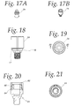
- FIGS. 17A and 17B are perspective views of a drive arm assembly in accordance with the present invention.
- FIG. 18 is a side view of the drive arm assembly illustrated in FIGS. 17A and 17B.
- FIG. 19 is a bottom view of the drive arm assembly illustrated in FIG. 18 .
- FIG. 20 is a sectional view along line 20 — 20 of FIG. 19 .
- FIG. 21 is a top view of the drive arm assembly illustrated in FIG. 18 .
- FIGS. 22A-22C illustrate the magnetic circuit for various positions of the magnet relative to the magnetic flux responsive element.
- FIG. 23 is a plan view of a race which forms a portion of the self-lubricating bearing in accordance with the present invention.
- the present invention relates to a self-lubricating bearing configured, for example, as a radial bearing, which includes a race and bearing element.
- the race is illustrated in FIGS. 23 and 24 while the bearing element is illustrated in FIGS. 17A-22.
- An important aspect of the invention is that the bearing surfaces on the race and the bearing element are configured to provide self-lubrication.
- the race and the bearing element are formed from homogeneous materials. Accordingly, the lubrication effect provided at the bearing surfaces will not be diminished as the mating bearing surfaces wear.
- FIGS. 23 and 24 illustrate the race while FIGS. 17A-22 illustrate the bearing element configured as a drive arm assembly for a rotary position sensor as generally illustrated in FIGS. 1-22.
- the present invention relates to a self-lubricating bearing suitable for use in automotive underbody applications.
- the self-lubricated bearing in accordance with the present invention includes a race 15 (FIGS. 23 and 24) and a bearing element 24 .
- the bearing element 24 includes an axial annular bearing surface 16 (FIG. 18) and a radial bearing surface 17 . These bearing surfaces 16 and 17 are adapted to mate within an interior bearing surface 18 (FIG. 22) formed on the interior surface of the race 15 .
- the annular axial bearing surface 16 (FIG. 18) on the bearing element or drive arm assembly 24 is adapted to mate with the inner surface 18 (FIG. 23) of the race 15 .
- the bearing surface 17 of the bearing element 24 in a radial plane is adapted to mate with one or the other of the radial surfaces 19 , 21 (FIG. 23) of the race 15 .
- the race 15 may be formed from metal.
- the race may be formed from a corrosion resistant metal such as ATSM 304 stainless steel with a fine finish.
- the bearing element or drive arm 24 may be homogeneously formed from a polymer, such as composite plastic material that is blended with PFTE or Teflon.
- the plastic material may be a thermoset or thermoplastic material, such as glass-filled 6-12 nylon with, for example, 15% Teflon.
- the bearing provides a metal-to-polymer bearing that is self-lubricating in which the Teflon migrates to the surface as the components wear for the life of the bearing. As such, unlike the self-lubricating bearings in the prior art, wear of the mating surfaces of the bearing components does not diminish the lubrication effect of the self-lubricating bearing.
- the bearing race 15 is disposed within a molded housing 22 for providing bearing surfaces for a rotatable bearing element or drive arm 24 as best shown in FIGS. 6 and 9.
- the rotary position sensor generally identified with the reference numeral 20 , includes a molded housing 22 , a drive arm assembly 24 and a rotor plate 26 .
- a lever arm assembly 28 which does not form part of the present invention, may be attached to the drive arm assembly 24 by a suitable fastener 30 .
- the lever arm 28 is adapted to be mechanically coupled to an external device whose rotational movement is to be sensed.
- the rotor plate 26 shown best in FIGS. 13-16, is formed with a rotor cavity 32 for receiving a pair of flux concentrators 34 , 35 (FIGS. 4 and 22 A- 22 C) and a magnetic responsive element 36 , such as a Hall effect IC and an optional flux shunt if required.
- the flux concentrators 34 , 35 may be formed from a soft magnetic material with semi-circular cross-section and disposed within the rotor cavity 32 along with the magnetic flux responsive element 36 .
- the flux concentrators 34 , 35 are disposed on opposing sides of the magnetic flux responsive element 36 and disposed within the rotor cavity 32 (FIGS. 22 A- 22 C).
- a printed circuit board 38 may be used to provide an electrical connection between the magnetic flux responsive element 36 and a plurality of terminals 40 (FIG. 4) disposed within the main housing 22 .
- the molded housing 22 is provided with a central aperture 42 (FIG. 7) for receiving the drive arm assembly 24 .
- one end 44 of the molded housing 22 is formed with a reduced diameter portion 46 which contacts an annular shoulder 49 (FIG. 20) on the drive arm assembly 24 to form a stop and limit axial movement of the drive arm assembly 24 in a direction of the arrow 47 .
- the other end 48 of the molded housing 22 is formed with annular stepped surfaces, generally identified with the reference numeral 50 (FIGS. 7 - 9 ).
- the rotor plate 26 is formed with corresponding annular stepped surfaces 52 (FIGS. 3, 6 , 13 and 14 ) that are adapted to mate with the stepped surfaces 50 formed in the molded housing 22 as best shown in FIGS. 3 and 6.
- the stepped surfaces 50 and 52 may be ultrasonically welded together.
- FIGS. 7-10 The details of the molded housing 22 are illustrated in FIGS. 7-10.
- the aperture 42 is formed with a radial slot 56 .
- the radial slot 56 is used to provide radial orientation of the rotor plate 26 relative to molded housing 22 .
- the rotor plate 26 is provided with a radial tab 58 (FIG. 12 ).
- the radial tab 58 is adapted to be received in the radial slot 56 (FIG. 10) to provide radial registration of the rotor plate 26 relative to the molded housing 22 .
- the rotor plate 26 is provided with an axially extending sleeve portion 60 .
- the sleeve portion 60 is adapted to be received in a hollow cavity 62 (FIG. 20) formed in the drive arm assembly 24 .
- the sleeve portion 60 of the rotor plate 26 is formed with a hollow cavity 62 (FIG. 13) for receiving one or more flux concentrators 34 , 35 (FIG. 4) and a magnetic flux responsive element 36 and flux shunt, if required.
- FIGS. 3 and 6 such a configuration allows the drive arm assembly 24 to rotate relative to the cavity 62 and thus also rotate relative to the flux concentrators 34 , 35 and the magnetic flux responsive element 36 (FIG. 4) and flux shunt, if used.
- the drive arm assembly 24 includes a generally circular magnet 64 and shunt ring 66 .
- the shunt ring 66 circumscribes the circular magnet 64 .
- the circular magnet 64 as well as the shunt ring 66 are axially aligned with a portion of the annular cavity formed in the axially extending portion 60 of the rotor plate 26 which results in the annular magnet 64 and shunt ring 66 being axially aligned with magnet 64 and shunt ring 66 , as best shown in FIG. 6 .
- rotation of the drive arm assembly 24 results in radial displacement of the circular magnet 64 relative to fixed position of the magnetic flux responsive element 36 and flux concentrators 34 , as shown in FIGS. 22A-22C and generate a signal representative thereof.
- the configuration of the magnet 64 illustrated in FIGS. 22A-22C is merely exemplary.
- the magnet 64 is shown as a diametrically charged magnet.
- the principles of the present invention are applicable to all magnet configurations including radially charged magnets (not shown).
Abstract
Description
Claims (8)
Priority Applications (6)
| Application Number | Priority Date | Filing Date | Title |
|---|---|---|---|
| US09/912,953 US6710593B2 (en) | 2001-07-25 | 2001-07-25 | Rotary position sensor with a self-lubricating bearing |
| CA002394668A CA2394668A1 (en) | 2001-07-25 | 2002-07-24 | Self-lubricating bearing for underbody automotive applications |
| MXPA02007277A MXPA02007277A (en) | 2001-07-25 | 2002-07-25 | Self-lubricating bearing for underbody automotive applications. |
| AT02016329T ATE343734T1 (en) | 2001-07-25 | 2002-07-25 | SELF-LUBRICATING BEARING FOR VEHICLE UNDERBODY APPLICATIONS |
| EP02016329A EP1279846B1 (en) | 2001-07-25 | 2002-07-25 | Self-lubricating bearing for underbody automotive applications |
| DE60215590T DE60215590T2 (en) | 2001-07-25 | 2002-07-25 | Self-lubricating bearing for applications in underbody of motor vehicles |
Applications Claiming Priority (1)
| Application Number | Priority Date | Filing Date | Title |
|---|---|---|---|
| US09/912,953 US6710593B2 (en) | 2001-07-25 | 2001-07-25 | Rotary position sensor with a self-lubricating bearing |
Publications (2)
| Publication Number | Publication Date |
|---|---|
| US20030160606A1 US20030160606A1 (en) | 2003-08-28 |
| US6710593B2 true US6710593B2 (en) | 2004-03-23 |
Family
ID=25432746
Family Applications (1)
| Application Number | Title | Priority Date | Filing Date |
|---|---|---|---|
| US09/912,953 Expired - Fee Related US6710593B2 (en) | 2001-07-25 | 2001-07-25 | Rotary position sensor with a self-lubricating bearing |
Country Status (6)
| Country | Link |
|---|---|
| US (1) | US6710593B2 (en) |
| EP (1) | EP1279846B1 (en) |
| AT (1) | ATE343734T1 (en) |
| CA (1) | CA2394668A1 (en) |
| DE (1) | DE60215590T2 (en) |
| MX (1) | MXPA02007277A (en) |
Cited By (8)
| Publication number | Priority date | Publication date | Assignee | Title |
|---|---|---|---|---|
| US20040100252A1 (en) * | 2002-05-15 | 2004-05-27 | Babin Brian George | Through the hole rotary position sensor |
| US20080184843A1 (en) * | 2005-03-23 | 2008-08-07 | Thomas Klotzbuecher | Accelerator Pedal Module With Magnetic Sensor |
| US20090309585A1 (en) * | 2006-10-31 | 2009-12-17 | The Furukawa Electric Co., Ltd | Rotation angle detection device |
| US20100066353A1 (en) * | 2006-10-31 | 2010-03-18 | The Furukawa Electric Co., Ltd | Rotation angle detection device |
| US8823366B2 (en) | 2009-11-16 | 2014-09-02 | Cts Corporation | Non-contacting sensor assembly |
| US9156059B2 (en) | 2011-05-16 | 2015-10-13 | New Hampshire Ball Bearings, Inc. | Self-lubricating surface coating composition |
| WO2016164514A1 (en) * | 2015-04-07 | 2016-10-13 | New Hampshire Ball Bearing, Inc. | Bearing with wear sensor |
| US10184520B2 (en) | 2010-12-05 | 2019-01-22 | New Hampshire Ball Bearing, Inc. | Self-lubricated bearing compositions and methods of making the same |
Families Citing this family (4)
| Publication number | Priority date | Publication date | Assignee | Title |
|---|---|---|---|---|
| US6974108B2 (en) * | 2003-12-04 | 2005-12-13 | William Fondriest | Lower bearing for aircraft landing gear |
| US7250756B1 (en) * | 2006-02-09 | 2007-07-31 | Timken Us Corporation | Flexible sensor input assembly |
| FR2902872B1 (en) * | 2006-06-27 | 2008-11-14 | Arvinmeritor Light Vehicle Sys | DEVICE FOR MEASURING MAGNETIC FIELD. |
| JP4950826B2 (en) * | 2007-10-03 | 2012-06-13 | ナイルス株式会社 | Non-contact rotation angle sensor |
Citations (27)
| Publication number | Priority date | Publication date | Assignee | Title |
|---|---|---|---|---|
| US3782794A (en) * | 1972-12-08 | 1974-01-01 | Textron Inc | Antifriction bearing |
| US4053190A (en) * | 1975-06-23 | 1977-10-11 | The Heim Universal Corporation | Self-aligning bearing with a split inner member |
| US4575145A (en) * | 1984-12-13 | 1986-03-11 | Wolfram Norman E | Differential axle for railroad car |
| US4866426A (en) * | 1988-06-17 | 1989-09-12 | The United States Of America As Represented By The Secretary Of The Navy | Magnetic amplifier housing and detector for an improved tamper alarm system |
| US5056938A (en) * | 1990-10-04 | 1991-10-15 | The Torrington Company | Track roller bearing floating sleeve system |
| US5061087A (en) * | 1990-10-15 | 1991-10-29 | Beloit Corporation | Bearing apparatus for a doctor journal |
| US5073051A (en) * | 1989-02-20 | 1991-12-17 | Mannesmann Aktiengesellschaft | Matrix pin print head having a shield to counter magnetic fields |
| US5073038A (en) * | 1990-07-12 | 1991-12-17 | Tuthill Corporation | Swivel bearing |
| US5164668A (en) * | 1991-12-06 | 1992-11-17 | Honeywell, Inc. | Angular position sensor with decreased sensitivity to shaft position variability |
| US5219231A (en) * | 1987-10-02 | 1993-06-15 | Plastic Bearing Housing Australiasia Pty Ltd. | Split race bearing assemblies |
| US5265965A (en) * | 1992-09-02 | 1993-11-30 | Rexnord Corporation | Composite ball and socket bearing with convex outer surface |
| US5273369A (en) * | 1991-07-02 | 1993-12-28 | Johnson Electric S.A. | Sheet metal bearing for an electric motor |
| US5444369A (en) * | 1993-02-18 | 1995-08-22 | Kearney-National, Inc. | Magnetic rotational position sensor with improved output linearity |
| US5462381A (en) * | 1990-04-20 | 1995-10-31 | Reliance Electric Industrial Company | Corrosion resistant bushing |
| US5542900A (en) * | 1994-09-09 | 1996-08-06 | Jason Incorporated | Idler roller and method of making |
| US5694039A (en) * | 1996-03-07 | 1997-12-02 | Honeywell Inc. | Angular position sensor having multiple magnetic circuits |
| USRE35855E (en) * | 1989-10-19 | 1998-07-21 | General Electric Company | Structured product dynamoelectric machine |
| US5789917A (en) * | 1990-12-05 | 1998-08-04 | Moving Magnet Technologie Sa | Magnetic position sensor with hall probe formed in an air gap of a stator |
| US5791787A (en) * | 1997-02-19 | 1998-08-11 | Reliance Electric Industrial Company | Corrosive resistant bearing assembly |
| US5836702A (en) * | 1997-08-27 | 1998-11-17 | Reliance Electric Industrial Company | Composite bearing housing |
| US5885006A (en) * | 1994-02-08 | 1999-03-23 | Plastic Bearings & Housings Australasia Pty. Ltd. | Plain bearing assembly |
| US5993065A (en) * | 1998-07-13 | 1999-11-30 | Chrysler Corporation | Universal slider bushing |
| US6130535A (en) * | 1996-08-24 | 2000-10-10 | Robert Bosch Gmbh | Measuring device for determination of rotary angle between stator and rotor |
| US6164829A (en) * | 1998-05-28 | 2000-12-26 | Trw Fahrwerksysteme Gmbh & Co. Kg | Bearing shell |
| US6194894B1 (en) * | 1996-12-04 | 2001-02-27 | Ab Eletronik Gmbh | Rotation angular sensor with metal-injection molded magnet holder |
| US20020153879A1 (en) * | 1999-09-09 | 2002-10-24 | Mikuni Corporation | Non-contact position sensor |
| US20030020465A1 (en) * | 2001-07-26 | 2003-01-30 | Wolf Ronald J. | Position sensor assembly utilizing magnetic field variations |
Family Cites Families (2)
| Publication number | Priority date | Publication date | Assignee | Title |
|---|---|---|---|---|
| US2804886A (en) * | 1955-11-04 | 1957-09-03 | Charles S White | Low friction fabric material |
| US3110530A (en) * | 1962-01-16 | 1963-11-12 | Gen Electric | Self-lubricating sleeve bearing |
-
2001
- 2001-07-25 US US09/912,953 patent/US6710593B2/en not_active Expired - Fee Related
-
2002
- 2002-07-24 CA CA002394668A patent/CA2394668A1/en not_active Abandoned
- 2002-07-25 DE DE60215590T patent/DE60215590T2/en not_active Expired - Lifetime
- 2002-07-25 AT AT02016329T patent/ATE343734T1/en not_active IP Right Cessation
- 2002-07-25 MX MXPA02007277A patent/MXPA02007277A/en unknown
- 2002-07-25 EP EP02016329A patent/EP1279846B1/en not_active Expired - Lifetime
Patent Citations (28)
| Publication number | Priority date | Publication date | Assignee | Title |
|---|---|---|---|---|
| US3782794A (en) * | 1972-12-08 | 1974-01-01 | Textron Inc | Antifriction bearing |
| US4053190A (en) * | 1975-06-23 | 1977-10-11 | The Heim Universal Corporation | Self-aligning bearing with a split inner member |
| US4575145A (en) * | 1984-12-13 | 1986-03-11 | Wolfram Norman E | Differential axle for railroad car |
| US5219231A (en) * | 1987-10-02 | 1993-06-15 | Plastic Bearing Housing Australiasia Pty Ltd. | Split race bearing assemblies |
| US4866426A (en) * | 1988-06-17 | 1989-09-12 | The United States Of America As Represented By The Secretary Of The Navy | Magnetic amplifier housing and detector for an improved tamper alarm system |
| US5073051A (en) * | 1989-02-20 | 1991-12-17 | Mannesmann Aktiengesellschaft | Matrix pin print head having a shield to counter magnetic fields |
| USRE35855E (en) * | 1989-10-19 | 1998-07-21 | General Electric Company | Structured product dynamoelectric machine |
| US5462381A (en) * | 1990-04-20 | 1995-10-31 | Reliance Electric Industrial Company | Corrosion resistant bushing |
| US5073038B1 (en) * | 1990-07-12 | 1999-05-11 | Tuthill Corp | Swivel bearing |
| US5073038A (en) * | 1990-07-12 | 1991-12-17 | Tuthill Corporation | Swivel bearing |
| US5056938A (en) * | 1990-10-04 | 1991-10-15 | The Torrington Company | Track roller bearing floating sleeve system |
| US5061087A (en) * | 1990-10-15 | 1991-10-29 | Beloit Corporation | Bearing apparatus for a doctor journal |
| US5789917A (en) * | 1990-12-05 | 1998-08-04 | Moving Magnet Technologie Sa | Magnetic position sensor with hall probe formed in an air gap of a stator |
| US5273369A (en) * | 1991-07-02 | 1993-12-28 | Johnson Electric S.A. | Sheet metal bearing for an electric motor |
| US5164668A (en) * | 1991-12-06 | 1992-11-17 | Honeywell, Inc. | Angular position sensor with decreased sensitivity to shaft position variability |
| US5265965A (en) * | 1992-09-02 | 1993-11-30 | Rexnord Corporation | Composite ball and socket bearing with convex outer surface |
| US5444369A (en) * | 1993-02-18 | 1995-08-22 | Kearney-National, Inc. | Magnetic rotational position sensor with improved output linearity |
| US5885006A (en) * | 1994-02-08 | 1999-03-23 | Plastic Bearings & Housings Australasia Pty. Ltd. | Plain bearing assembly |
| US5542900A (en) * | 1994-09-09 | 1996-08-06 | Jason Incorporated | Idler roller and method of making |
| US5694039A (en) * | 1996-03-07 | 1997-12-02 | Honeywell Inc. | Angular position sensor having multiple magnetic circuits |
| US6130535A (en) * | 1996-08-24 | 2000-10-10 | Robert Bosch Gmbh | Measuring device for determination of rotary angle between stator and rotor |
| US6194894B1 (en) * | 1996-12-04 | 2001-02-27 | Ab Eletronik Gmbh | Rotation angular sensor with metal-injection molded magnet holder |
| US5791787A (en) * | 1997-02-19 | 1998-08-11 | Reliance Electric Industrial Company | Corrosive resistant bearing assembly |
| US5836702A (en) * | 1997-08-27 | 1998-11-17 | Reliance Electric Industrial Company | Composite bearing housing |
| US6164829A (en) * | 1998-05-28 | 2000-12-26 | Trw Fahrwerksysteme Gmbh & Co. Kg | Bearing shell |
| US5993065A (en) * | 1998-07-13 | 1999-11-30 | Chrysler Corporation | Universal slider bushing |
| US20020153879A1 (en) * | 1999-09-09 | 2002-10-24 | Mikuni Corporation | Non-contact position sensor |
| US20030020465A1 (en) * | 2001-07-26 | 2003-01-30 | Wolf Ronald J. | Position sensor assembly utilizing magnetic field variations |
Cited By (13)
| Publication number | Priority date | Publication date | Assignee | Title |
|---|---|---|---|---|
| US20040100252A1 (en) * | 2002-05-15 | 2004-05-27 | Babin Brian George | Through the hole rotary position sensor |
| US20070252591A1 (en) * | 2002-05-15 | 2007-11-01 | Siemens Vdo Automotive Corporatin | Through the hole rotary position sensor |
| US7301328B2 (en) * | 2002-05-15 | 2007-11-27 | Siemens Vdo Automotive Corporation | Through the hole rotary position sensor with a pair of pole pieces disposed around the periphery of the circular magnet |
| US7378842B2 (en) | 2002-05-15 | 2008-05-27 | Continental Automotive Systems Us, Inc. | Through the hole rotary position sensor with non-symmetric pole pieces |
| US20080184843A1 (en) * | 2005-03-23 | 2008-08-07 | Thomas Klotzbuecher | Accelerator Pedal Module With Magnetic Sensor |
| US20100066353A1 (en) * | 2006-10-31 | 2010-03-18 | The Furukawa Electric Co., Ltd | Rotation angle detection device |
| US20090309585A1 (en) * | 2006-10-31 | 2009-12-17 | The Furukawa Electric Co., Ltd | Rotation angle detection device |
| US8823366B2 (en) | 2009-11-16 | 2014-09-02 | Cts Corporation | Non-contacting sensor assembly |
| US10184520B2 (en) | 2010-12-05 | 2019-01-22 | New Hampshire Ball Bearing, Inc. | Self-lubricated bearing compositions and methods of making the same |
| US9156059B2 (en) | 2011-05-16 | 2015-10-13 | New Hampshire Ball Bearings, Inc. | Self-lubricating surface coating composition |
| US9314815B2 (en) | 2011-05-16 | 2016-04-19 | New Hampshire Ball Bearing, Inc. | Method for making a bearing having a self-lubricating surface coating |
| WO2016164514A1 (en) * | 2015-04-07 | 2016-10-13 | New Hampshire Ball Bearing, Inc. | Bearing with wear sensor |
| US9951820B2 (en) | 2015-04-07 | 2018-04-24 | New Hampshire Ball Bearings, Inc. | Bearing with wear sensor |
Also Published As
| Publication number | Publication date |
|---|---|
| EP1279846A2 (en) | 2003-01-29 |
| US20030160606A1 (en) | 2003-08-28 |
| MXPA02007277A (en) | 2004-08-12 |
| EP1279846B1 (en) | 2006-10-25 |
| CA2394668A1 (en) | 2003-01-25 |
| DE60215590T2 (en) | 2007-08-30 |
| ATE343734T1 (en) | 2006-11-15 |
| DE60215590D1 (en) | 2006-12-07 |
| EP1279846A3 (en) | 2004-06-30 |
Similar Documents
| Publication | Publication Date | Title |
|---|---|---|
| US6710593B2 (en) | Rotary position sensor with a self-lubricating bearing | |
| US7868611B2 (en) | Rotary angle detecting device | |
| US8028575B2 (en) | Liquid level detecting device | |
| US7498803B2 (en) | Rotation angle detection device having bearing supported yoke fixed to object being detected | |
| US6252394B1 (en) | Rotary movement sensor equipped with means of assembly with a drive shaft designed to minimize the effects of a misalignment in the connection | |
| US20110181221A1 (en) | Motor | |
| US6172847B1 (en) | Rotational assembly for disc drive device having small runout and reduced axial displacement | |
| US7265537B2 (en) | Annular sensor housing | |
| US7988363B2 (en) | Bearing with rotation detection device | |
| US5238254A (en) | Ferrofluid seal apparatus | |
| US20060016256A1 (en) | Filling level sensor for a tank | |
| US6323643B1 (en) | Rotary position sensor having a semi-parabolic magnet | |
| US6566865B2 (en) | Non-contact rotational displacement detecting device | |
| KR20010089237A (en) | Inhibitor switch | |
| KR0155005B1 (en) | Miniature electric motor having bearing unit | |
| JPWO2005040730A1 (en) | Rotation angle detector | |
| JPS63266671A (en) | Conductive sliding device | |
| US6870364B2 (en) | Connection structure of non-contact rotary sensor with rotating shaft | |
| EP0319264A1 (en) | Rotary shaft position reed switch | |
| JPH0245046B2 (en) | SUBERIJIKUKESOCHI | |
| US6297629B1 (en) | Device for measuring rotation having magnetic relative positioning of encoder and sensor | |
| CN105277117A (en) | Position detecting device | |
| EP1279926A2 (en) | Mechanical design for a sensor to prevent an ice lock condition | |
| JPS58157365A (en) | Stepping motor with member responding in linear line | |
| CN113007301B (en) | Linear transmission device |
Legal Events
| Date | Code | Title | Description |
|---|---|---|---|
| AS | Assignment |
Owner name: AMERICAN ELECTRONIC COMPONENTS, INDIANA Free format text: ASSIGNMENT OF ASSIGNORS INTEREST;ASSIGNORS:BABIN, BRIAN GEORGE;BROWN, TODD ANTHONY;REEL/FRAME:012030/0687 Effective date: 20010725 |
|
| AS | Assignment |
Owner name: DANA CORPORATION, OHIO Free format text: ASSIGNMENT OF ASSIGNORS INTEREST;ASSIGNOR:AMERICAN ELECTRONIC COMPONENTS, INC.;REEL/FRAME:012618/0778 Effective date: 20020123 |
|
| AS | Assignment |
Owner name: AMERICAN ELECTRONIC COMPONENTS, INC., INDIANA Free format text: CORRECTION;ASSIGNORS:BABIN, BRIAN G.;BROWN, TODD A.;REEL/FRAME:013354/0247 Effective date: 20010725 |
|
| AS | Assignment |
Owner name: AMERICAN ELECTRONIC COMPONENTS, INC., INDIANA Free format text: ASSIGNMENT OF ASSIGNORS INTEREST;ASSIGNOR:DANA CORPORATION;REEL/FRAME:013482/0509 Effective date: 20021101 |
|
| AS | Assignment |
Owner name: DANA GLOBAL HOLDINGS, INC., OHIO Free format text: SECURITY AGREEMENT;ASSIGNOR:AMERICAN ELECTRONIC COMPONENTS, INC.;REEL/FRAME:013532/0757 Effective date: 20021115 |
|
| FEPP | Fee payment procedure |
Free format text: PAYOR NUMBER ASSIGNED (ORIGINAL EVENT CODE: ASPN); ENTITY STATUS OF PATENT OWNER: LARGE ENTITY |
|
| AS | Assignment |
Owner name: SIEMENS VDO AUTOMOTIVE CORPORATION, MICHIGAN Free format text: ASSIGNMENT OF ASSIGNORS INTEREST;ASSIGNOR:AMERICAN ELECTRONIC COMPONENTS, INC.;REEL/FRAME:017073/0404 Effective date: 20051206 Owner name: AMERICAN ELECTRONIC COMPONENTS, INC., INDIANA Free format text: RELEASE BY SECURED PARTY;ASSIGNOR:DANA GLOBAL HOLDINGS, INC.;REEL/FRAME:017073/0661 Effective date: 20051206 |
|
| FPAY | Fee payment |
Year of fee payment: 4 |
|
| FEPP | Fee payment procedure |
Free format text: PAYER NUMBER DE-ASSIGNED (ORIGINAL EVENT CODE: RMPN); ENTITY STATUS OF PATENT OWNER: LARGE ENTITY Free format text: PAYOR NUMBER ASSIGNED (ORIGINAL EVENT CODE: ASPN); ENTITY STATUS OF PATENT OWNER: LARGE ENTITY |
|
| FPAY | Fee payment |
Year of fee payment: 8 |
|
| AS | Assignment |
Owner name: CONTINENTAL AUTOMOTIVE SYSTEMS US, INC., MICHIGAN Free format text: CHANGE OF NAME;ASSIGNOR:SIEMENS VDO AUTOMOTIVE CORPORATION;REEL/FRAME:034979/0865 Effective date: 20071203 |
|
| AS | Assignment |
Owner name: CONTINENTAL AUTOMOTIVE SYSTEMS, INC., MICHIGAN Free format text: MERGER;ASSIGNOR:CONTINENTAL AUTOMOTIVE SYSTEMS US, INC.;REEL/FRAME:035091/0577 Effective date: 20121212 |
|
| REMI | Maintenance fee reminder mailed | ||
| LAPS | Lapse for failure to pay maintenance fees | ||
| STCH | Information on status: patent discontinuation |
Free format text: PATENT EXPIRED DUE TO NONPAYMENT OF MAINTENANCE FEES UNDER 37 CFR 1.362 |
|
| FP | Lapsed due to failure to pay maintenance fee |
Effective date: 20160323 |