US6708569B2 - Method of operating an electromagnetic flowmeter - Google Patents
Method of operating an electromagnetic flowmeter Download PDFInfo
- Publication number
- US6708569B2 US6708569B2 US10/157,930 US15793002A US6708569B2 US 6708569 B2 US6708569 B2 US 6708569B2 US 15793002 A US15793002 A US 15793002A US 6708569 B2 US6708569 B2 US 6708569B2
- Authority
- US
- United States
- Prior art keywords
- excitation current
- voltage
- voltage pulses
- measuring electrodes
- fluid
- Prior art date
- Legal status (The legal status is an assumption and is not a legal conclusion. Google has not performed a legal analysis and makes no representation as to the accuracy of the status listed.)
- Expired - Lifetime
Links
- 238000000034 method Methods 0.000 title claims abstract description 45
- 230000005284 excitation Effects 0.000 claims abstract description 61
- 238000005259 measurement Methods 0.000 claims abstract description 15
- 230000001939 inductive effect Effects 0.000 claims abstract description 9
- 239000012530 fluid Substances 0.000 claims description 39
- 230000000737 periodic effect Effects 0.000 claims description 7
- 239000007788 liquid Substances 0.000 abstract description 21
- 230000002452 interceptive effect Effects 0.000 abstract description 16
- 238000000576 coating method Methods 0.000 abstract description 5
- 239000002245 particle Substances 0.000 abstract description 3
- 230000000712 assembly Effects 0.000 description 4
- 238000000429 assembly Methods 0.000 description 4
- 230000008901 benefit Effects 0.000 description 4
- 230000001419 dependent effect Effects 0.000 description 4
- 238000010586 diagram Methods 0.000 description 4
- 230000000694 effects Effects 0.000 description 4
- 230000006399 behavior Effects 0.000 description 3
- 230000015572 biosynthetic process Effects 0.000 description 3
- 238000011156 evaluation Methods 0.000 description 3
- 238000004519 manufacturing process Methods 0.000 description 3
- 238000012986 modification Methods 0.000 description 3
- 230000004048 modification Effects 0.000 description 3
- 239000004300 potassium benzoate Substances 0.000 description 3
- 238000005070 sampling Methods 0.000 description 3
- PNEYBMLMFCGWSK-UHFFFAOYSA-N Alumina Chemical compound [O-2].[O-2].[O-2].[Al+3].[Al+3] PNEYBMLMFCGWSK-UHFFFAOYSA-N 0.000 description 2
- 229920001875 Ebonite Polymers 0.000 description 2
- 239000004176 azorubin Substances 0.000 description 2
- 230000033228 biological regulation Effects 0.000 description 2
- 239000000919 ceramic Substances 0.000 description 2
- 230000008859 change Effects 0.000 description 2
- 239000000555 dodecyl gallate Substances 0.000 description 2
- 239000002184 metal Substances 0.000 description 2
- 239000004033 plastic Substances 0.000 description 2
- -1 polyfluoroethylene Polymers 0.000 description 2
- 230000008569 process Effects 0.000 description 2
- 230000009467 reduction Effects 0.000 description 2
- 230000001105 regulatory effect Effects 0.000 description 2
- 239000004289 sodium hydrogen sulphite Substances 0.000 description 2
- 239000003990 capacitor Substances 0.000 description 1
- 230000001143 conditioned effect Effects 0.000 description 1
- 239000004020 conductor Substances 0.000 description 1
- 238000011161 development Methods 0.000 description 1
- 230000005674 electromagnetic induction Effects 0.000 description 1
- 230000010363 phase shift Effects 0.000 description 1
- 230000001052 transient effect Effects 0.000 description 1
Images


Classifications
-
- G—PHYSICS
- G01—MEASURING; TESTING
- G01F—MEASURING VOLUME, VOLUME FLOW, MASS FLOW OR LIQUID LEVEL; METERING BY VOLUME
- G01F1/00—Measuring the volume flow or mass flow of fluid or fluent solid material wherein the fluid passes through a meter in a continuous flow
- G01F1/56—Measuring the volume flow or mass flow of fluid or fluent solid material wherein the fluid passes through a meter in a continuous flow by using electric or magnetic effects
- G01F1/58—Measuring the volume flow or mass flow of fluid or fluent solid material wherein the fluid passes through a meter in a continuous flow by using electric or magnetic effects by electromagnetic flowmeters
- G01F1/588—Measuring the volume flow or mass flow of fluid or fluent solid material wherein the fluid passes through a meter in a continuous flow by using electric or magnetic effects by electromagnetic flowmeters combined constructions of electrodes, coils or magnetic circuits, accessories therefor
-
- G—PHYSICS
- G01—MEASURING; TESTING
- G01F—MEASURING VOLUME, VOLUME FLOW, MASS FLOW OR LIQUID LEVEL; METERING BY VOLUME
- G01F1/00—Measuring the volume flow or mass flow of fluid or fluent solid material wherein the fluid passes through a meter in a continuous flow
- G01F1/56—Measuring the volume flow or mass flow of fluid or fluent solid material wherein the fluid passes through a meter in a continuous flow by using electric or magnetic effects
- G01F1/58—Measuring the volume flow or mass flow of fluid or fluent solid material wherein the fluid passes through a meter in a continuous flow by using electric or magnetic effects by electromagnetic flowmeters
- G01F1/60—Circuits therefor
Definitions
- This invention relates to a method of operating an electromagnetic flowmeter for measuring the volumetric flow rate of an electrically conductive and flowing liquid.
- Electromagnetic flowmeters commonly comprise a flow sensor and measuring and control electronics coupled thereto. In the following, only flowmeters or flow sensors will be spoken of if necessary for simplicity.
- electromagnetic flowmeters measure the volumetric flow rate of an electrically conductive liquid flowing in a pipe; thus, per definitionem, the liquid volume flowing through a pipe cross section per unit time is measured.
- the flow sensor has a, usually nonferromagnetic, flow tube which is connected into the pipe in a liquid-tight manner, e.g., by means of flanges or threaded joints.
- the portion of the flow tube which contacts the liquid is generally electrically nonconductive, so that a voltage induced in the liquid according to Faraday's law of electromagnetic induction by a magnetic field cutting across the flow tube will not be short-circuited.
- metal flow tubes are commonly provided with a nonconductive lining, e.g., a lining of hard rubber, polyfluoroethylene, etc., and are generally nonferromagnetic; in the case of flow tubes made completely of plastic or ceramic, particularly of alumina ceramic, the nonconductive lining is not necessary.
- a nonconductive lining e.g., a lining of hard rubber, polyfluoroethylene, etc.
- the magnetic field is produced by means of two coil assemblies, each of which is, in the most frequent case, positioned on the outside of the flow tube along a diameter of the latter.
- Each coil assembly commonly consists of an air-core coil or of a coil with a soft magnetic core.
- the coils are, in the most frequent and simplest case, identical and electrically connected in series, so that in operation they can be traversed by the same excitation current. It is also known to cause the same excitation current to flow through the coils alternately in the same and the opposite direction, see U.S. Pat. No. 5,646,353, in order to be able to measure the viscosity of non-Newtonian fluids, i.e., of fluids of high viscosity.
- the excitation current just mentioned is produced by control electronics; it is regulated at a constant value of, e.g., 85 mA, and its direction is periodically reversed; this prevents the development of electrochemical interference voltages at the measuring electrodes.
- the current reversal is achieved by incorporating the coils in a so-called T network or a so-called H network; for the current regulation and current reversal, see U.S. Pat. No. 4,410,926 or U.S. Pat. No. 6,031,740.
- the aforementioned induced voltage is developed between at least two galvanic, i.e., liquid-wetted, measuring electrodes, or between at least two capacitive measuring electrodes, i.e., two electrodes disposed in the wall of the flow tube, for example, with each of the electrodes picking off a separate potential.
- the measuring electrodes are arranged at diametrically opposed positions such that their common diameter is perpendicular to the direction of the magnetic field and, thus, perpendicular to the diameter on which the coil assemblies are located.
- the induced voltage is amplified, and the amplified voltage is conditioned by means of evaluation electronics to form a measurement signal which is recorded, displayed, or further processed.
- the potential at each electrode is not only dependent on the magnetic field according to Faraday's law—the geometrical/spatial dimensions of the flow tube and the properties of the liquid enter into this dependence—, but interfering potentials of different geneses are superimposed on this measurement signal, which is based on Faraday's law and should be as pure as possible.
- the absolute value of the potential at the respective electrode is immaterial for the measurement of volumetric flow rate, but only on condition that, on the one hand, the potentials lie in the dynamic range of a differential amplifier following the measuring electrodes, i.e., that this amplifier must not be overdriven by the potentials, and that, on the other hand, the frequency of potential changes differs appreciably from the frequency of the above-mentioned current reversal.
- a first kind of interfering potential results from inductive and/or capacitive interference which arises from coil assemblies and their leads and changes the electric charge on the capacitor that exists at the interface between electrode and liquid.
- the interfering potential of one electrode generally differs from the interfering potential of the other electrode.
- This—first—effect may, on the one hand, restrict the dynamic range of the differential amplifier.
- the value of the difference between the interfering potentials of the electrodes is subject to variances in flow-sensor parameters due to manufacturing tolerances.
- the determinable dependence of the potentials of the measuring electrodes on the velocity of the liquid is partly due to this effect, because at low velocities, the above-mentioned charges at the interface between electrode and liquid are not removed by the latter.
- a second kind of interfering potential is caused by particles of foreign matter or by air bubbles which are entrained by the liquid and which, when hitting an electrode, cause sudden changes in the potential of the latter.
- the decay time of these changes is dependent on the type of liquid and is in any case greater than the transient time of the changes.
- a third kind of interfering potential is caused by coatings deposited by the liquid on the measuring electrodes, as is also described in U.S. Pat. No. 5,210,496, for example.
- the formation of the coatings is very strongly dependent on the velocity of the liquid. The differences in the behavior of the individual flow sensor units are even further increased by the formation of the coatings.
- JP-A 10213466 proposes to apply voltages generated by means of the measuring and control circuit to at least one of the two measuring electrodes at least temporarily within a period in which the excitation current does not flow and in which consequently no voltage is induced in the fluid.
- the temporarily applied voltage serves to measure and evaluate the interface capacitances built up at the measuring electrodes, i.e., in effect to compensate interfering potentials of the first and/or third kinds.
- a disadvantage of the prior-art flow sensors is that because of the intermediate turning off of the excitation current, the flow rate can only be sampled very coarsely.
- the invention provides a method of operating an electromagnetic flowmeter having a flow tube connected into a fluid-conveying line, said method comprising the steps of:
- an electromagnetic flowmeter for a fluid flowing in a line comprising:
- a flow tube connectable into the line for conducting the fluid
- At least two measuring electrodes for picking off potentials which are induced in the fluid flowing through the flow tube, which fluid is penetrated by the magnetic field
- means controlled by the measuring and control circuit for generating voltage pulses at the measuring electrodes said means for generating voltage pulses being controlled such that the voltage pulses are applied to the measuring electrodes when the excitation current is different from zero.
- the discharge voltage is an at least intermittently periodic sequence of voltage pulses.
- the excitation current is at least intermittently clocked periodically with a predeterminable period, with the period of the clocked excitation current being different from a period of the sequence of voltage pulses.
- the period of the clocked excitation current is greater than the period of the sequence of voltage pulses.
- two successive voltage pulses are of like polarity.
- two successive voltage pulses are of different polarity.
- the voltage pulses have a width substantially smaller than a pulse width of the excitation current.
- voltage pulses are applied intermittently to both measuring electrodes.
- One fundamental idea of the invention is to largely prevent or compensate interfering potentials of the kinds described, on the one hand, by repeated application of the discharge voltage, particularly at as high a clock rate as possible, and, on the other hand, by constant reversal of the polarity of the discharge voltage, and, despite this discharge process, except for the usual reduction in dynamic range due to the polarity reversal of the magnetic field, to have to trade off no or only a minimum reduction in the sampling frequency of the measurement voltage induced in the fluid.
- Another fundamental idea of the invention is to apply the discharge voltage to the measuring electrodes at a rate of change, i.e., a repetition rate, higher than the rate of change of the interfering potentials, thus causing charges on the interface and/or stray capacitances which on a time average are substantially uniform.
- One advantage of the invention is that the interfering potentials resulting from inductive/capacitive interference, the interfering potentials resulting from particles of foreign matter and/or air bubbles entrained by the liquid, and the interfering potentials resulting from the formation of measuring-electrode coatings can be selectively reduced or even eliminated, so that the wide manufacturing spread can be minimized and flow sensor units of uniform behavior can be manufactured.
- Another advantage of the invention is that despite the discharge processes initiated at the measuring electrodes, flow rate can be measured with a high resolution in comparison with that of conventional flowmeters.
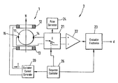
- FIG. 1 shows schematically, and partly in block-diagram form, an electromagnetic flowmeter suitable for carrying out the method of the invention
- FIG. 2 a is a portion of a timing diagram showing the periodically reversed excitation current flowing in the coils during different phases;
- FIG. 2 b is a portion of the timing diagram showing the potential induced by the excitation current of FIG. 2 at one of the two measuring electrodes, this electrode being supplied, according to one embodiment of the method of the invention, with several double voltage pulses of one polarity followed by double voltage pulses of the other polarity;
- FIG. 2 c is a portion of the timing diagram showing the potential induced by the excitation current of FIG. 2 at one of the two measuring electrodes, this electrode being supplied, according to another embodiment of the method of the invention, with several single voltage pulses of one polarity followed by single voltage pulses of the other polarity.
- the flowmeter with which the method of the invention can be carried out comprises a flow sensor 1 and a measuring and control circuit.
- Flow sensor 1 includes a flow tube 11 , which has a tube wall and through which in operation the conductive liquid to be measured flows in the direction of a longitudinal tube axis.
- an inner portion of flow tube 11 which contacts the liquid, is electrically nonconductive.
- metal flow tubes are commonly provided with an electrically nonconductive lining, e.g., a lining of hard rubber, polyfluoroethylene, etc, and are generally nonferromagnetic; in the case of flow tubes made completely of plastic or ceramic, particularly of alumina ceramic, the electrically nonconductive lining is not necessary.
- a coil assembly of flow sensor 1 has a first field coil 12 and a second field coil 13 , which are mounted on flow tube 11 .
- the field coils are located on a first diameter of flow tube 11 .
- the coil assembly serves to produce a magnetic field H which cuts across the tube wall and the liquid.
- the magnetic field is set up when an excitation current is caused to flow in field coils 12 , 13 , which in this embodiment are connected in series.
- the preferably bipolar excitation current may be, for instance, a square-wave, triangular, or sinusoidal current.
- FIG. 1 shows that field coils 12 , 13 are so-called air-core coils, i.e., that they are coreless. These coils, as is usual with such coil arrangements, may also be wound on a core which will generally be soft magnetic, and the cores may cooperate with pole pieces; see, for instance, U.S. Pat. No. 5,540,103.
- the coil assembly is preferably so designed, and in particular the two field coils 12 , 13 are so shaped and dimensioned, that within flow tube 11 , the magnetic field H produced with the coil assembly is symmetric, particularly rotationally symmetric, at least with respect to a second diameter which is perpendicular to the first.
- the excitation current I serving to produce the magnetic field H is generated by a suitable excitation-current generator 20 .
- a direct current from a direct-current source particularly a current regulated at a constant amplitude, is periodically switched in excitation-current generator 20 by means of a polarity reverser and applied to the coil assembly, such that coils 12 , 13 are traversed by the current in a first direction during a first phase PH 11 and in a direction opposite to the first direction during a succeeding second phase PH 12 ; for the current regulation and polarity reversal, see also U.S. Pat. Nos. 4,410,926 or 6,031,740, for example.
- the second phase PH 12 is followed by a third phase PH 21 , during which the excitation current I flows in the first direction again.
- the third phase is followed by a fourth phase PH 22 , during which the excitation current I flows in the opposite direction again.
- This is followed by a corresponding phase PH 31 etc.
- pairs of successive phases form respective reversing cycles P 1 , P 2 , P 3 , etc.
- the polarity of the magnetic field H is reversed, see FIG. 2 a.
- a first electrode 14 positioned on the inside of the wall of flow tube 11 , serves to pick off a first potential induced by the magnetic field H.
- a second electrode 15 also positioned on the inside of the tube wall, serves to pick off a second potential induced by the magnetic field.
- the measuring electrodes 14 , 15 are located on the second diameter of flow tube 11 , which is perpendicular to the first diameter and, thus, to the longitudinal tube axis. They may also be located, for example, on a chord of flow tube 11 which is parallel to the second diameter, see also U.S. Pat. No. 5,646,353.
- the measuring electrodes 14 , 15 are galvanic electrodes, i.e., electrodes which contact the liquid. It is also possible to use two capacitive electrodes, i.e., electrodes disposed within the wall of flow tube 11 , for example. Each electrode picks off a separate electric potential which in operation is induced in the liquid according to Faraday's law.
- the measuring and control electronics 2 comprise a changeover switch which must have one set of changeover contacts for each electrode. Since two measuring electrodes 14 , 15 are present in FIG. 2, the associated changeover switch 21 has two sets of changeover contacts, which are not shown separately but are represented by the changeover-switch symbol.
- measuring electrodes 14 and 15 are respectively connected to an inverting input and a noninverting input of a differential amplifier 22 .
- evaluation electronics 23 compute a measurement signal d proportional to the volumetric flow rate of the liquid in the usual manner, e.g., by periodic sampling and holding; cf., for example, U.S. Pat. Nos. 4,382,387, 4,422,337, or 4,704,908.
- Changeover switch 21 is in the position shown in FIG. 1 during a first subcycle T 111 of the first phase PHI 1 of the excitation current I, during a first subcycle T 121 of the second phase PH 12 of the excitation current I, during a first subcycle T 211 of the third phase PH 21 of the excitation current I, during a first subcycle T 221 of the fourth phase PH 22 of the excitation current I, and during a first subcycle T 311 of a fifth phase PH 31 of the excitation current I, see FIGS. 2 a and 2 c.
- Changeover switch 21 is controlled by a sequence controller 25 ; one of the outputs of the latter is coupled to the control input of changeover switch 21 .
- changeover switch 21 Another output of changeover switch 21 is connected to a control input of excitation-current generator 20 , and a further output is connected to evaluation electronics 23 .
- Sequence controller 25 has a clock generator associated with it. In the other position of changeover switch 21 , which is not shown in FIG. 1, at least one of the two measuring electrodes 14 , 15 is connected to a pulse generator 24 .
- Changeover switch 21 is in this other position during a second subcycle T 112 , T 122 , T 212 , T 222 , T 312 of at least one of the phases PH 11 , PH 12 , PH 21 , PH 22 , PH 31 of the excitation current I, so that a discharge voltage E is applied at least intermittently, particularly periodically, to at least one of the two measuring electrodes 14 , 15 , with the excitation current I continuing to flow.
- the charges transferred by means of a discharge voltage E which preferably consists of a sequence of voltage pulses, serve to charge any interfaces at the measuring electrodes 14 , 15 as uniformly as possible and/or to at least partly compensate any interfering potentials existing at the electrode.
- the application of the discharge voltage E to the respective electrode 14 , 15 includes connecting the respective electrode to a circuit ground of the flowmeter, particularly to a circuit ground of flow sensor 1 .
- changing a charge on the respective electrode also comprises removing charge from the electrode.
- a duration for which the discharge voltage is effective, i.e., for which charge is transferred from or to the measuring electrodes in the above sense, may be very short compared to the duration of the second subcycle, as shown; its maximum duration is equal to the duration of the second subcycle.
- FIG. 2 b shows one of the many possible time sequences of the preferably short-time application of the discharge voltage to one of the measuring electrodes 14 , 15 .
- respective positive voltage pulses E 112 , E 122 , E 312 are applied.
- respective negative voltage pulses E 212 , E 222 are applied.
- the pair of positive voltage pulses E 112 , E 122 and the pair of negative voltage pulses E 212 , E 222 which are applied during the reversing cycles P 1 and P 2 , respectively, and thus act during the two opposite directions of the excitation current I, represent respective double voltage pulses.
- FIG. 2 c shows another possible time sequence of the application of the discharge voltage E to at least one of the measuring electrodes 14 , 15 .
- a positive voltage pulse E 112 ′, E 312 ′ is applied.
- a negative voltage pulse E 212 ′ is applied.
- a positive and a negative voltage pulse are applied alternately during only one direction of the excitation current I.
- any combination of sequences of positive and/or negative discharge voltages For example, if required, fewer voltage pulses than shown in FIGS. 2 b and 2 c may be applied. “Fewer” means, for example, that a voltage pulse is applied only in every fifth or tenth reversing cycle of the excitation current I.
- the voltage pulses are shown as needle pulses of very small width as compared to the pulse width of the excitation current I, but their shape may also be square, triangular, trapezoidal, or sinusoidal. Furthermore, the voltage pulses need not be of the same amplitude, as shown, but the amplitude may vary from voltage pulse to voltage pulse. The period of the voltage pulses need not be constant, either, but may vary; it must not exceed the duration of the second subcycle, of course.
- the pulse generator 24 is preferably a single-ended DC power source which is briefly connected to the electrode 14 or 15 by means of changeover switch 21 .
- the DC power source preferably has as high an internal resistance as possible.
- the DC power source is a single-ended DC source having as low an internal resistance as possible.
- the power source of the measuring and control electronics 2 it is possible to use instead of a separate DC source the power source of the measuring and control electronics 2 ; a separate DC source can thus be dispensed with.
Landscapes
- Physics & Mathematics (AREA)
- Electromagnetism (AREA)
- Fluid Mechanics (AREA)
- General Physics & Mathematics (AREA)
- Measuring Volume Flow (AREA)
Abstract
The flowmeter comprises a flow sensor with a flow tube, two coils, and two measuring electrodes as well as measuring and control electronics. The method serves to compensate interfering potentials that are caused by inductive and/or capacitive interference arising from the coil leads and/or by particles of foreign matter or air bubbles in the liquid to be measured and/or by coatings on the measuring electrodes. During first subcycles of the excitation current, a measurement signal proportional to volumetric flow rate is computed as usual. During second subcycles of the excitation current, at least one voltage pulse is applied to at least one of the measuring electrodes.
Description
This application claims the benefit of provisional No. 60/310,254 filed on Aug. 7, 2001.
This invention relates to a method of operating an electromagnetic flowmeter for measuring the volumetric flow rate of an electrically conductive and flowing liquid.
Electromagnetic flowmeters commonly comprise a flow sensor and measuring and control electronics coupled thereto. In the following, only flowmeters or flow sensors will be spoken of if necessary for simplicity.
As is well known, electromagnetic flowmeters measure the volumetric flow rate of an electrically conductive liquid flowing in a pipe; thus, per definitionem, the liquid volume flowing through a pipe cross section per unit time is measured.
The flow sensor has a, usually nonferromagnetic, flow tube which is connected into the pipe in a liquid-tight manner, e.g., by means of flanges or threaded joints. The portion of the flow tube which contacts the liquid is generally electrically nonconductive, so that a voltage induced in the liquid according to Faraday's law of electromagnetic induction by a magnetic field cutting across the flow tube will not be short-circuited.
Therefore, metal flow tubes are commonly provided with a nonconductive lining, e.g., a lining of hard rubber, polyfluoroethylene, etc., and are generally nonferromagnetic; in the case of flow tubes made completely of plastic or ceramic, particularly of alumina ceramic, the nonconductive lining is not necessary.
The magnetic field is produced by means of two coil assemblies, each of which is, in the most frequent case, positioned on the outside of the flow tube along a diameter of the latter. Each coil assembly commonly consists of an air-core coil or of a coil with a soft magnetic core.
To ensure that the magnetic field produced by the coils is as homogeneous as possible, the coils are, in the most frequent and simplest case, identical and electrically connected in series, so that in operation they can be traversed by the same excitation current. It is also known to cause the same excitation current to flow through the coils alternately in the same and the opposite direction, see U.S. Pat. No. 5,646,353, in order to be able to measure the viscosity of non-Newtonian fluids, i.e., of fluids of high viscosity.
The excitation current just mentioned is produced by control electronics; it is regulated at a constant value of, e.g., 85 mA, and its direction is periodically reversed; this prevents the development of electrochemical interference voltages at the measuring electrodes. The current reversal is achieved by incorporating the coils in a so-called T network or a so-called H network; for the current regulation and current reversal, see U.S. Pat. No. 4,410,926 or U.S. Pat. No. 6,031,740.
The aforementioned induced voltage is developed between at least two galvanic, i.e., liquid-wetted, measuring electrodes, or between at least two capacitive measuring electrodes, i.e., two electrodes disposed in the wall of the flow tube, for example, with each of the electrodes picking off a separate potential.
In the most frequent case, the measuring electrodes are arranged at diametrically opposed positions such that their common diameter is perpendicular to the direction of the magnetic field and, thus, perpendicular to the diameter on which the coil assemblies are located. The induced voltage is amplified, and the amplified voltage is conditioned by means of evaluation electronics to form a measurement signal which is recorded, displayed, or further processed.
The potential at each electrode is not only dependent on the magnetic field according to Faraday's law—the geometrical/spatial dimensions of the flow tube and the properties of the liquid enter into this dependence—, but interfering potentials of different geneses are superimposed on this measurement signal, which is based on Faraday's law and should be as pure as possible.
In principle, the absolute value of the potential at the respective electrode is immaterial for the measurement of volumetric flow rate, but only on condition that, on the one hand, the potentials lie in the dynamic range of a differential amplifier following the measuring electrodes, i.e., that this amplifier must not be overdriven by the potentials, and that, on the other hand, the frequency of potential changes differs appreciably from the frequency of the above-mentioned current reversal.
A first kind of interfering potential results from inductive and/or capacitive interference which arises from coil assemblies and their leads and changes the electric charge on the capacitor that exists at the interface between electrode and liquid. As a result of asymmetries in the concrete structure of the flow sensor, particularly as far as the conductor routing to the coil assemblies and the measuring electrodes is concerned, the interfering potential of one electrode generally differs from the interfering potential of the other electrode.
This—first—effect may, on the one hand, restrict the dynamic range of the differential amplifier. On the other hand, the value of the difference between the interfering potentials of the electrodes is subject to variances in flow-sensor parameters due to manufacturing tolerances. Also, the determinable dependence of the potentials of the measuring electrodes on the velocity of the liquid is partly due to this effect, because at low velocities, the above-mentioned charges at the interface between electrode and liquid are not removed by the latter.
A second kind of interfering potential is caused by particles of foreign matter or by air bubbles which are entrained by the liquid and which, when hitting an electrode, cause sudden changes in the potential of the latter. The decay time of these changes is dependent on the type of liquid and is in any case greater than the transient time of the changes.
This—second—effect, too, results in an erroneous measurement signal. The resulting error is also dependent on the potential of the electrode. Since this potential varies from flow sensor to flow sensor due to manufacturing tolerances as was explained above, the second effect adds to the first effect, so that the individual flow sensor units differ widely in their behaviors, which, of course, is highly undesirable.
A third kind of interfering potential is caused by coatings deposited by the liquid on the measuring electrodes, as is also described in U.S. Pat. No. 5,210,496, for example. The formation of the coatings is very strongly dependent on the velocity of the liquid. The differences in the behavior of the individual flow sensor units are even further increased by the formation of the coatings.
JP-A 10213466 proposes to apply voltages generated by means of the measuring and control circuit to at least one of the two measuring electrodes at least temporarily within a period in which the excitation current does not flow and in which consequently no voltage is induced in the fluid. In the flowmeter disclosed in JP-A 10213466, the temporarily applied voltage serves to measure and evaluate the interface capacitances built up at the measuring electrodes, i.e., in effect to compensate interfering potentials of the first and/or third kinds.
A disadvantage of the prior-art flow sensors is that because of the intermediate turning off of the excitation current, the flow rate can only be sampled very coarsely.
It is an object of the invention to provide a method whereby the aforementioned interfering potentials can be prevented as effectively as possible or at least be largely compensated, and which simultaneously permits high-resolution sampling of the flow rate.
To attain this object, the invention provides a method of operating an electromagnetic flowmeter having a flow tube connected into a fluid-conveying line, said method comprising the steps of:
causing the fluid to flow through the flow tube;
causing a, particularly bipolar, excitation current generated by means of a measuring and control circuit of the flowmeter to flow through a coil assembly mounted on the flow tube for producing a magnetic field cutting across the fluid;
inducing a voltage in the moving fluid for changing potentials applied at measuring electrodes positioned at the flow tube;
removing potentials applied to the measuring electrodes for producing a measurement signal derived from the voltage induced in the moving fluid; and
applying at least intermittently a discharge voltage generated by a measuring and control circuit to at least one of the measuring electrodes during the flow of the excitation current through the coil assembly.
Furthermore, the invention provides an electromagnetic flowmeter for a fluid flowing in a line, comprising:
a flow tube connectable into the line for conducting the fluid;
a measuring and control circuit;
means fed by the measuring and control circuit for producing a magnetic field cutting across the flow tube with a coil assembly mounted on the flow tube and traversed by an excitation current;
at least two measuring electrodes for picking off potentials which are induced in the fluid flowing through the flow tube, which fluid is penetrated by the magnetic field;
means connected at least intermittently to the measuring electrodes for generating at least one measurement signal derived from the potentials induced in the fluid; and
means controlled by the measuring and control circuit for generating voltage pulses at the measuring electrodes, said means for generating voltage pulses being controlled such that the voltage pulses are applied to the measuring electrodes when the excitation current is different from zero.
In a first preferred embodiment of the method of the invention, the discharge voltage is an at least intermittently periodic sequence of voltage pulses.
In a second preferred embodiment of the method of the invention, the excitation current is at least intermittently clocked periodically with a predeterminable period, with the period of the clocked excitation current being different from a period of the sequence of voltage pulses.
In a third preferred embodiment of the method of the invention, the period of the clocked excitation current is greater than the period of the sequence of voltage pulses.
In a fourth preferred embodiment of the method of the invention, two successive voltage pulses are of like polarity.
In a fifth preferred embodiment of the method of the invention, two successive voltage pulses are of different polarity.
In a sixth preferred embodiment of the method of the invention, the voltage pulses have a width substantially smaller than a pulse width of the excitation current.
In a seventh preferred embodiment of the method of the invention, voltage pulses are applied intermittently to both measuring electrodes.
One fundamental idea of the invention is to largely prevent or compensate interfering potentials of the kinds described, on the one hand, by repeated application of the discharge voltage, particularly at as high a clock rate as possible, and, on the other hand, by constant reversal of the polarity of the discharge voltage, and, despite this discharge process, except for the usual reduction in dynamic range due to the polarity reversal of the magnetic field, to have to trade off no or only a minimum reduction in the sampling frequency of the measurement voltage induced in the fluid. Another fundamental idea of the invention is to apply the discharge voltage to the measuring electrodes at a rate of change, i.e., a repetition rate, higher than the rate of change of the interfering potentials, thus causing charges on the interface and/or stray capacitances which on a time average are substantially uniform.
One advantage of the invention is that the interfering potentials resulting from inductive/capacitive interference, the interfering potentials resulting from particles of foreign matter and/or air bubbles entrained by the liquid, and the interfering potentials resulting from the formation of measuring-electrode coatings can be selectively reduced or even eliminated, so that the wide manufacturing spread can be minimized and flow sensor units of uniform behavior can be manufactured. Another advantage of the invention is that despite the discharge processes initiated at the measuring electrodes, flow rate can be measured with a high resolution in comparison with that of conventional flowmeters.
The method of the invention and further advantages will now be explained in greater detail with reference to the accompanying drawings, in which:
FIG. 1 shows schematically, and partly in block-diagram form, an electromagnetic flowmeter suitable for carrying out the method of the invention;
FIG. 2a is a portion of a timing diagram showing the periodically reversed excitation current flowing in the coils during different phases;
FIG. 2b is a portion of the timing diagram showing the potential induced by the excitation current of FIG. 2 at one of the two measuring electrodes, this electrode being supplied, according to one embodiment of the method of the invention, with several double voltage pulses of one polarity followed by double voltage pulses of the other polarity; and
FIG. 2c is a portion of the timing diagram showing the potential induced by the excitation current of FIG. 2 at one of the two measuring electrodes, this electrode being supplied, according to another embodiment of the method of the invention, with several single voltage pulses of one polarity followed by single voltage pulses of the other polarity.
While the invention is susceptible to various modifications and alternative forms, exemplary embodiments thereof have been shown by way of example in the drawings and will herein be described in detail. It should be understood, however, that there is no intent to limit the invention to the the particular forms diclosed, but on the contrary, the intention is to cover all modifications, equivalents, and alternatives falling within the spirit and scope of the invention as defined by the intended claims.
The flowmeter with which the method of the invention can be carried out comprises a flow sensor 1 and a measuring and control circuit. Flow sensor 1 includes a flow tube 11, which has a tube wall and through which in operation the conductive liquid to be measured flows in the direction of a longitudinal tube axis.
To avoid creating a short circuit for voltages induced in the fluid, an inner portion of flow tube 11, which contacts the liquid, is electrically nonconductive. For this purpose, metal flow tubes are commonly provided with an electrically nonconductive lining, e.g., a lining of hard rubber, polyfluoroethylene, etc, and are generally nonferromagnetic; in the case of flow tubes made completely of plastic or ceramic, particularly of alumina ceramic, the electrically nonconductive lining is not necessary.
A coil assembly of flow sensor 1 has a first field coil 12 and a second field coil 13, which are mounted on flow tube 11. The field coils are located on a first diameter of flow tube 11. In operation, the coil assembly serves to produce a magnetic field H which cuts across the tube wall and the liquid. The magnetic field is set up when an excitation current is caused to flow in field coils 12, 13, which in this embodiment are connected in series. The preferably bipolar excitation current may be, for instance, a square-wave, triangular, or sinusoidal current.
FIG. 1 shows that field coils 12, 13 are so-called air-core coils, i.e., that they are coreless. These coils, as is usual with such coil arrangements, may also be wound on a core which will generally be soft magnetic, and the cores may cooperate with pole pieces; see, for instance, U.S. Pat. No. 5,540,103.
The coil assembly is preferably so designed, and in particular the two field coils 12, 13 are so shaped and dimensioned, that within flow tube 11, the magnetic field H produced with the coil assembly is symmetric, particularly rotationally symmetric, at least with respect to a second diameter which is perpendicular to the first.
As shown in FIG. 1, the excitation current I serving to produce the magnetic field H is generated by a suitable excitation-current generator 20. Preferably, a direct current from a direct-current source, particularly a current regulated at a constant amplitude, is periodically switched in excitation-current generator 20 by means of a polarity reverser and applied to the coil assembly, such that coils 12, 13 are traversed by the current in a first direction during a first phase PH11 and in a direction opposite to the first direction during a succeeding second phase PH12; for the current regulation and polarity reversal, see also U.S. Pat. Nos. 4,410,926 or 6,031,740, for example.
The second phase PH12 is followed by a third phase PH21, during which the excitation current I flows in the first direction again. The third phase is followed by a fourth phase PH22, during which the excitation current I flows in the opposite direction again. This is followed by a corresponding phase PH31 etc. With respect to the reversal of the direction of the excitation current I, pairs of successive phases form respective reversing cycles P1, P2, P3, etc. Essentially in synchronism with the reversal of the excitation current I flowing through the coil assembly, except for any phase shift that may be present, the polarity of the magnetic field H is reversed, see FIG. 2a.
A first electrode 14, positioned on the inside of the wall of flow tube 11, serves to pick off a first potential induced by the magnetic field H. A second electrode 15, also positioned on the inside of the tube wall, serves to pick off a second potential induced by the magnetic field. The measuring electrodes 14, 15 are located on the second diameter of flow tube 11, which is perpendicular to the first diameter and, thus, to the longitudinal tube axis. They may also be located, for example, on a chord of flow tube 11 which is parallel to the second diameter, see also U.S. Pat. No. 5,646,353.
In FIG. 1, the measuring electrodes 14, 15 are galvanic electrodes, i.e., electrodes which contact the liquid. It is also possible to use two capacitive electrodes, i.e., electrodes disposed within the wall of flow tube 11, for example. Each electrode picks off a separate electric potential which in operation is induced in the liquid according to Faraday's law.
The measuring and control electronics 2 comprise a changeover switch which must have one set of changeover contacts for each electrode. Since two measuring electrodes 14, 15 are present in FIG. 2, the associated changeover switch 21 has two sets of changeover contacts, which are not shown separately but are represented by the changeover-switch symbol.
In the position of changeover switch 21 shown in FIG. 1, measuring electrodes 14 and 15 are respectively connected to an inverting input and a noninverting input of a differential amplifier 22. Thus, the difference of the two potentials picked off by measuring electrodes 14, 15 is obtained. From this difference, evaluation electronics 23 compute a measurement signal d proportional to the volumetric flow rate of the liquid in the usual manner, e.g., by periodic sampling and holding; cf., for example, U.S. Pat. Nos. 4,382,387, 4,422,337, or 4,704,908.
Another output of changeover switch 21 is connected to a control input of excitation-current generator 20, and a further output is connected to evaluation electronics 23. Sequence controller 25 has a clock generator associated with it. In the other position of changeover switch 21, which is not shown in FIG. 1, at least one of the two measuring electrodes 14, 15 is connected to a pulse generator 24. Changeover switch 21 is in this other position during a second subcycle T112, T122, T212, T222, T312 of at least one of the phases PH11, PH12, PH21, PH22, PH31 of the excitation current I, so that a discharge voltage E is applied at least intermittently, particularly periodically, to at least one of the two measuring electrodes 14, 15, with the excitation current I continuing to flow. The charges transferred by means of a discharge voltage E, which preferably consists of a sequence of voltage pulses, serve to charge any interfaces at the measuring electrodes 14, 15 as uniformly as possible and/or to at least partly compensate any interfering potentials existing at the electrode.
According to the invention, the application of the discharge voltage E to the respective electrode 14, 15 includes connecting the respective electrode to a circuit ground of the flowmeter, particularly to a circuit ground of flow sensor 1. In other words, changing a charge on the respective electrode also comprises removing charge from the electrode. A duration for which the discharge voltage is effective, i.e., for which charge is transferred from or to the measuring electrodes in the above sense, may be very short compared to the duration of the second subcycle, as shown; its maximum duration is equal to the duration of the second subcycle.
FIG. 2b shows one of the many possible time sequences of the preferably short-time application of the discharge voltage to one of the measuring electrodes 14, 15. In subcycles T112, T122, T312, respective positive voltage pulses E112, E122, E312 are applied. In subcycles T212, T222, respective negative voltage pulses E212, E222 are applied.
The pair of positive voltage pulses E112, E122 and the pair of negative voltage pulses E212, E222, which are applied during the reversing cycles P1 and P2, respectively, and thus act during the two opposite directions of the excitation current I, represent respective double voltage pulses.
FIG. 2c shows another possible time sequence of the application of the discharge voltage E to at least one of the measuring electrodes 14, 15. During each of subcycles T112, T312, a positive voltage pulse E112′, E312′ is applied. During subcycle T212, a negative voltage pulse E212′ is applied. In FIG. 2c, a positive and a negative voltage pulse are applied alternately during only one direction of the excitation current I.
It is within the scope of the invention to use any combination of sequences of positive and/or negative discharge voltages. For example, if required, fewer voltage pulses than shown in FIGS. 2b and 2 c may be applied. “Fewer” means, for example, that a voltage pulse is applied only in every fifth or tenth reversing cycle of the excitation current I.
In FIGS. 2b and 2 c, the voltage pulses are shown as needle pulses of very small width as compared to the pulse width of the excitation current I, but their shape may also be square, triangular, trapezoidal, or sinusoidal. Furthermore, the voltage pulses need not be of the same amplitude, as shown, but the amplitude may vary from voltage pulse to voltage pulse. The period of the voltage pulses need not be constant, either, but may vary; it must not exceed the duration of the second subcycle, of course.
The pulse generator 24 is preferably a single-ended DC power source which is briefly connected to the electrode 14 or 15 by means of changeover switch 21. The DC power source preferably has as high an internal resistance as possible.
In FIGS. 2b and 2 c it is assumed that the DC power source is a single-ended DC source having as low an internal resistance as possible. In this case, it is possible to use instead of a separate DC source the power source of the measuring and control electronics 2; a separate DC source can thus be dispensed with.
While the invention has been illustrated and described in detail in the drawings and forgoing description, such illustration and description is to be considered as exemplary not restrictive in character, it being understood that only exemplary embodiments have been shown and described and that all changes and modifications that come within the spirit and scope of the invention as described herein are desired to protected.
Claims (26)
1. A method of operating an electromagnetic flowmeter having a flow tube connected into a fluid-conveying line, said method comprising the steps of:
causing the fluid to flow through the flow tube;
causing a, particularly bipolar, excitation current generated by means of a measuring and control circuit of the flowmeter to flow through a coil assembly mounted on the flow tube for producing a magnetic field cutting across the fluid;
inducing a voltage in the moving fluid for changing potentials applied at measuring electrodes positioned at the flow tube;
removing potentials applied to the measuring electrodes for producing a measurement signal derived from the voltage induced in the moving fluid; and
applying at least intermittently a discharge voltage generated by a measuring and control circuit to at least one of the measuring electrodes during the flow of the excitation current through the coil assembly.
2. A method as claimed in claim 1 wherein the discharge voltage is an at least intermittently periodic sequence of voltage pulses.
3. A method as claimed in claim 2 wherein two successive voltage pulses are of like polarity.
4. A method as claimed in claim 2 wherein two successive voltage pulses are of different polarity.
5. A method as claimed in claim 2 , wherein the voltage pulses have a width substantially smaller than a pulse width of the excitation current.
6. A method as claimed in claim 2 , wherein voltage pulses are applied intermittently to both measuring electrodes.
7. A method as claimed in claim 3 , wherein the voltage pulses have a width substantially smaller than a pulse width of the excitation current.
8. A method as claimed in claim 3 , wherein voltage pulses are applied intermittently to both measuring electrodes.
9. A method as claimed in claim 4 , wherein voltage pulses are applied intermittently to both measuring electrodes.
10. A method as claimed in claim 1 , wherein voltage pulses are applied intermittently to both measuring electrodes.
11. An electromagnetic flowmeter for a fluid flowing in a line, comprising:
a flow tube connectable into the line for conducting the fluid;
a measuring and control circuit;
means fed by said measuring and control circuit for producing a magnetic field cutting across said flow tube with a coil assembly mounted on said low tube and traversed by an excitation current, said excitation current being clocked periodically;
at least two measuring electrodes for picking off potentials which are induced in the fluid flowing through said flow tube, which fluid is penetrated by the magnetic field;
means connected at least intermittently to said measuring electrodes for generating at least one measurement signal derived from the potentials induced in the fluid; and
means controlled by said measuring and control circuit for generating a discharge voltage at the measuring electrodes, said discharge voltage being a periodic sequence of voltage pulses, and said means for generating a discharge voltage in the form of voltage pulses being controlled such that the voltage pulses are applied to said measuring electrodes when the excitation current is different from zero, wherein:
a period of said clocked excitation current is different from a period of said sequence of voltage pulses.
12. The flowmeter as claimed in claim 11 , wherein the period of the clocked excitation current is greater than the period of the sequence of voltage pulses.
13. The flowmeter as claimed in claim 11 , wherein two successive voltage pulses are of like polarity.
14. The flowmeter as claimed in claim 11 , wherein two succesive voltage pulses are of different polarity.
15. The flowmeter as claimed in claim 11 , wherein the voltage pulses have a pulse width being substantially smaller than a pulse width of the excitation current.
16. the flowmeter as claimed in claim 11 , wherein the voltage oulses are applied intermittently to both measuring electrodes.
17. A method of operating an electromagnetic flowmeter having a flow tube connected into a fluid-conveying line, said method comprising the steps of:
causing the fluid to flow through the flow tube;
causing a, particularly bipolar, excitation current generated by means of a measuring and control circuit of the flowmeter to flow though a coil assembly mounted on the flow tube for producing a magnetic field cutting across the fluid;
inducing a voltage in the moving fluid for changing potentials applied at measuring electrodes positioned at the flow tube;
removing potentials applied to the measuring electrodes for producing a measurement signal derived from the voltage induced in the moving fluid; and
applying at least intermittently a discharge voltage generated by a measuring and control circuit to at least one of the measuring electrodes during the flow of the excitation current though the coil assembly, wherein:
the discharge voltage is an at least intermittently periodic sequence of voltage pulses; and
the excitation current is at least intermittently clocked periodically with a predetermined period, with the period of the clocked excitation current being different from a period of the sequence of voltage pulses.
18. A method as claimed in claim 17 , wherein the period of the clocked excitation current is greater than the period of the sequence of voltage pulses.
19. A method as claimed in claim 18 , wherein the voltage pulses have a width substantially smaller than a pulse width of the excitation current.
20. A method as claimed in claim 18 , wherein voltage pulses are applied intermittently to both measuring electrodes.
21. A method as claimed in claim 17 , wherein the voltage pulses have a width substantially smaller than a pulse width of the excitation current.
22. A method as claimed in claim 17 , wherein voltage pulses are applied intermittently to both measuring electrodes.
23. A method of operating an electromagnetic flowmeter having a flow tube connected into a fluid-conveying line, said method comprising the steps of causing the fluid to flow though the flow tube;
causing a, particularly bipolar, excitation current generated by means of a measuring and control circuit of the flowmeter to flow though a coil assembly mounted on the flow tube for producing a magnetic field cutting across the fluid;
inducing a voltage in the moving fluid for changing potentials applied at measuring electrodes positioned at the flow tube;
removing potentials applied to the measuring electrodes for producing a measurement signal derived from the voltage induced in the moving fluid; and
applying at least intermittently a discharge voltage generated by a measuring and control circuit to at least one of the measuring electrodes during the flow of the excitation current through the coil assembly, wherein:
The voltage pulses have a width substantially smaller than a pulse width of the excitation current.
24. A method as claimed in claim 23 , wherein voltage pulses are applied intermittently to both measuring electrodes.
25. A method of operating an electromagnetic flowmeter having a flow tube connected into a fluid-conveying line, said method comprising the steps of:
causing the fluid to flow through the flow tube;
causing a, particularly bipolar, excitation current generated by means of a measuring and control circuit of the flowmeter to flow through a coil assembly mounted on the flow tube for producing a magnetic field cutting across the fluid;
inducing a voltage in the moving fluid for changing potentials applied at measuring electrodes positioned at the flow tube;
removing potentials applied to the measuring electrodes for producing a measurement signal derived from the voltage induced in the moving fluid; and
applying at least intermittently a discharge voltage generated by a measuring and control circuit to at least one of the measuring electrodes during the flow of the excitation current through the coil assembly, wherein:
the discharge voltage is an at least intermittently periodic sequence of voltage pulses;
two successive voltage pulses are of like polarity; and
The voltage pulses have a width substantially smaller than a pulse width of the excitation current.
26. A method of operating an electromagnetic flowmeter having a flow tube connected into a fluid-conveying line, said method comprising the steps of:
causing the fluid to flow through the flow tube;
causing a, particularly bipolar, excitation current generated by means of a measuring and control circuit of the flowmeter to flow through a coil assembly mounted on the flow tube for producing a magnetic field cutting across the fluid′
inducing voltage in the moving fluid for changing potentials applied at measuring electrodes positioned at the flow tube;
removing potentials applied to the measuring electrodes for producing a measurement signal derived from the voltage induced in the moving fluid; and
applying at least intermittently a discharge voltage generated by a measuring and control circuit to at least one of the measuring electrodes during the flow of the excitation current through the coil assembly, wherein:
the discharge voltage is an at least intermittently periodic sequence of voltage pulses;
two successive voltage pulses are of different polarity; and
voltage pulses are applied intermittently to both measuring electrodes.
Priority Applications (1)
| Application Number | Priority Date | Filing Date | Title |
|---|---|---|---|
| US10/157,930 US6708569B2 (en) | 2001-07-06 | 2002-05-31 | Method of operating an electromagnetic flowmeter |
Applications Claiming Priority (5)
| Application Number | Priority Date | Filing Date | Title |
|---|---|---|---|
| EP01116432A EP1273891A1 (en) | 2001-07-06 | 2001-07-06 | Method for driving an electromagnetic flowmeter |
| EP01116432 | 2001-07-06 | ||
| EP01116432.4 | 2001-07-06 | ||
| US31025401P | 2001-08-07 | 2001-08-07 | |
| US10/157,930 US6708569B2 (en) | 2001-07-06 | 2002-05-31 | Method of operating an electromagnetic flowmeter |
Publications (2)
| Publication Number | Publication Date |
|---|---|
| US20030005777A1 US20030005777A1 (en) | 2003-01-09 |
| US6708569B2 true US6708569B2 (en) | 2004-03-23 |
Family
ID=27224201
Family Applications (1)
| Application Number | Title | Priority Date | Filing Date |
|---|---|---|---|
| US10/157,930 Expired - Lifetime US6708569B2 (en) | 2001-07-06 | 2002-05-31 | Method of operating an electromagnetic flowmeter |
Country Status (1)
| Country | Link |
|---|---|
| US (1) | US6708569B2 (en) |
Cited By (10)
| Publication number | Priority date | Publication date | Assignee | Title |
|---|---|---|---|---|
| US20040154409A1 (en) * | 2002-05-16 | 2004-08-12 | Gerd Stange | Method for measuring a medium that flows through a measuring tube |
| US20060095217A1 (en) * | 2004-11-01 | 2006-05-04 | Rosemount Inc. | Magnetic flowmeter with built-in simulator |
| US20060260415A1 (en) * | 2005-04-26 | 2006-11-23 | Severn Trent Metering Services Limited | Meter |
| US20070035309A1 (en) * | 2005-07-16 | 2007-02-15 | Dieter Keese | Method and device for detecting physical-chemical states on measuring electrodes of a flowmeter |
| DE102007015368A1 (en) | 2007-03-28 | 2008-10-02 | Endress + Hauser Flowtec Ag | Method for operating a magnetic-inductive flowmeter |
| US20090173168A1 (en) * | 2005-04-26 | 2009-07-09 | David Cottam | Meter |
| WO2014019779A2 (en) | 2012-07-30 | 2014-02-06 | Endress+Hauser Flowtec Ag | Electronic measuring device and measuring system formed therewith |
| US8869612B2 (en) | 2011-03-08 | 2014-10-28 | Baxter International Inc. | Non-invasive radio frequency liquid level and volume detection system using phase shift |
| US9163967B2 (en) | 2010-04-17 | 2015-10-20 | University Of Huddersfield | Electromagnetic flow meter and method for monitoring fluid flow of a conducting fluid having either a uniform or a non-uniform flow profile |
| US20180045545A1 (en) * | 2015-03-11 | 2018-02-15 | Endress + Hauser Flowtec Ag | Magneto-inductive flow measuring device with reduced electrical current draw |
Families Citing this family (5)
| Publication number | Priority date | Publication date | Assignee | Title |
|---|---|---|---|---|
| WO2004070323A1 (en) * | 2003-02-10 | 2004-08-19 | Gambro Lundia Ab | A flow sensor and method for measuring a flow rate component of a fluid containing electrically charged elements |
| DE102004057680A1 (en) * | 2004-11-29 | 2006-06-01 | Endress + Hauser Flowtec Ag | Magnetically inductive flow rate sensor function monitoring method for industry, involves monitoring sensor function based on receive signal induced by temporally changing magnetic field in coil serving as receiver |
| JP5574191B2 (en) * | 2012-06-26 | 2014-08-20 | 横河電機株式会社 | Electromagnetic flowmeter operation verification system |
| US11085803B2 (en) * | 2015-09-24 | 2021-08-10 | Micro Motion, Inc. | Entrained fluid detection diagnostic |
| DE102017112950A1 (en) * | 2017-06-13 | 2018-12-13 | Krohne Messtechnik Gmbh | Magnetic-inductive flowmeter and method for operating a magnetic-inductive flowmeter |
Citations (8)
| Publication number | Priority date | Publication date | Assignee | Title |
|---|---|---|---|---|
| US3783687A (en) * | 1972-05-26 | 1974-01-08 | Fischer & Porter Co | Electromagnetic flowmeter with square-wave excitation |
| US4206641A (en) * | 1977-08-10 | 1980-06-10 | Tokyo Shibaura Electric Co., Ltd. | Electromagnetic flow meter |
| US4210022A (en) * | 1977-10-05 | 1980-07-01 | Flowtec Ag | Method for the inductive measurement of fluid flow |
| US4545257A (en) * | 1982-09-30 | 1985-10-08 | Tokyo Shibaura Denki Kabushiki Kaisha | Electromagnetic flow meter |
| US4651286A (en) * | 1983-06-23 | 1987-03-17 | Yokogawa Hokushin Electric Corporation | Electromagnetic flowmeter |
| US4704908A (en) | 1985-10-23 | 1987-11-10 | Flowtec Ag | Method for compensating interference voltages in the electrode circuit in magnetic-inductive flow measurement |
| US4723449A (en) * | 1985-11-25 | 1988-02-09 | Danfoss A/S | Electromagnetic flowmeters |
| EP0336615A1 (en) | 1988-03-29 | 1989-10-11 | Aichi Tokei Denki Co., Ltd. | Electromagnetic flowmeter capable of simultaneous measurement of flow rate and conductivity of fluid |
-
2002
- 2002-05-31 US US10/157,930 patent/US6708569B2/en not_active Expired - Lifetime
Patent Citations (9)
| Publication number | Priority date | Publication date | Assignee | Title |
|---|---|---|---|---|
| US3783687A (en) * | 1972-05-26 | 1974-01-08 | Fischer & Porter Co | Electromagnetic flowmeter with square-wave excitation |
| US4206641A (en) * | 1977-08-10 | 1980-06-10 | Tokyo Shibaura Electric Co., Ltd. | Electromagnetic flow meter |
| US4210022A (en) * | 1977-10-05 | 1980-07-01 | Flowtec Ag | Method for the inductive measurement of fluid flow |
| US4545257A (en) * | 1982-09-30 | 1985-10-08 | Tokyo Shibaura Denki Kabushiki Kaisha | Electromagnetic flow meter |
| US4651286A (en) * | 1983-06-23 | 1987-03-17 | Yokogawa Hokushin Electric Corporation | Electromagnetic flowmeter |
| US4704908A (en) | 1985-10-23 | 1987-11-10 | Flowtec Ag | Method for compensating interference voltages in the electrode circuit in magnetic-inductive flow measurement |
| US4723449A (en) * | 1985-11-25 | 1988-02-09 | Danfoss A/S | Electromagnetic flowmeters |
| EP0336615A1 (en) | 1988-03-29 | 1989-10-11 | Aichi Tokei Denki Co., Ltd. | Electromagnetic flowmeter capable of simultaneous measurement of flow rate and conductivity of fluid |
| US4969363A (en) | 1988-03-29 | 1990-11-13 | Aichi Tokei Denki Co., Ltd. | Electromagnetic flowmeter capable of simultaneous measurement of flow rate and conductivity of fluid |
Non-Patent Citations (2)
| Title |
|---|
| Patent Abstract of Japan, vol. 1998, No. 13, Nov. 30, 1998, JP 10 213466, Yokogawa Electric Corp. |
| Patent Abstract of Japan. vol. 1998, No. 11, Sep. 30, 1998, JP 10 170317, Yokogawa Electric Corp. |
Cited By (19)
| Publication number | Priority date | Publication date | Assignee | Title |
|---|---|---|---|---|
| US20040154409A1 (en) * | 2002-05-16 | 2004-08-12 | Gerd Stange | Method for measuring a medium that flows through a measuring tube |
| US7028558B2 (en) * | 2002-05-16 | 2006-04-18 | Fachhochschule Kiel | Method for measuring a medium that flows through a measuring tube |
| US20060095217A1 (en) * | 2004-11-01 | 2006-05-04 | Rosemount Inc. | Magnetic flowmeter with built-in simulator |
| US7073393B2 (en) | 2004-11-01 | 2006-07-11 | Rosemount Inc. | Magnetic flowmeter with built-in simulator |
| US20090173168A1 (en) * | 2005-04-26 | 2009-07-09 | David Cottam | Meter |
| US20060260415A1 (en) * | 2005-04-26 | 2006-11-23 | Severn Trent Metering Services Limited | Meter |
| US7827870B2 (en) | 2005-04-26 | 2010-11-09 | Severn Trent Metering Services Limited | Meter |
| US20070035309A1 (en) * | 2005-07-16 | 2007-02-15 | Dieter Keese | Method and device for detecting physical-chemical states on measuring electrodes of a flowmeter |
| US7265544B2 (en) * | 2005-07-16 | 2007-09-04 | Abb Patent Gmbh | Method and device for detecting physical-chemical states on measuring electrodes of a flowmeter |
| DE102007015368A1 (en) | 2007-03-28 | 2008-10-02 | Endress + Hauser Flowtec Ag | Method for operating a magnetic-inductive flowmeter |
| US9163967B2 (en) | 2010-04-17 | 2015-10-20 | University Of Huddersfield | Electromagnetic flow meter and method for monitoring fluid flow of a conducting fluid having either a uniform or a non-uniform flow profile |
| US8869612B2 (en) | 2011-03-08 | 2014-10-28 | Baxter International Inc. | Non-invasive radio frequency liquid level and volume detection system using phase shift |
| US9829366B2 (en) | 2011-03-08 | 2017-11-28 | Baxter International Inc. | Non-invasive radio frequency liquid level and volume detection system and method using phase shift |
| US9907908B2 (en) | 2011-03-08 | 2018-03-06 | Baxter International Inc. | Non-invasive radio frequency medical fluid level and volume detection system and method |
| WO2014019779A3 (en) * | 2012-07-30 | 2014-03-27 | Endress+Hauser Flowtec Ag | Electronic measuring device for a magnetic-inductive flow meter, and measuring system formed therewith |
| DE102012106926A1 (en) | 2012-07-30 | 2014-05-15 | Endress + Hauser Flowtec Ag | Measuring electronics and thus formed measuring system |
| WO2014019779A2 (en) | 2012-07-30 | 2014-02-06 | Endress+Hauser Flowtec Ag | Electronic measuring device and measuring system formed therewith |
| US9304021B2 (en) | 2012-07-30 | 2016-04-05 | Endress + Hauser Flowtec Ag | Measuring electronics as well as measuring system formed therewith |
| US20180045545A1 (en) * | 2015-03-11 | 2018-02-15 | Endress + Hauser Flowtec Ag | Magneto-inductive flow measuring device with reduced electrical current draw |
Also Published As
| Publication number | Publication date |
|---|---|
| US20030005777A1 (en) | 2003-01-09 |
Similar Documents
| Publication | Publication Date | Title |
|---|---|---|
| US6708569B2 (en) | Method of operating an electromagnetic flowmeter | |
| USRE45447E1 (en) | Method of operating an electromagnetic flowmeter | |
| EP0336615B1 (en) | Electromagnetic flowmeter capable of simultaneous measurement of flow rate and conductivity of fluid | |
| AU740417B2 (en) | Electrode integrity checking | |
| EP2338035B1 (en) | Method for the energy-saving operation of a magnetic-inductive flow meter | |
| US7260486B2 (en) | Method for operating and/or reviewing a magneto-inductive flow meter | |
| CN101657699B (en) | Method for operating a magnetic-inductive flow meter | |
| US20060080049A1 (en) | Method for operating a process-measuring device | |
| US10712185B2 (en) | Magnetic-inductive flowmeter and method for operating a magnetic-inductive flowmeter | |
| JP2003097986A5 (en) | ||
| US20130197831A1 (en) | Fluid flow rate measuring device and water meter | |
| EP3268698B1 (en) | Magnetic-inductive flow meter with reduced current draw | |
| CN114829883A (en) | Method for operating a magnetically inductive flow meter | |
| WO2001090701A2 (en) | Conduction indication in a magnetic flowmeter | |
| US20100024567A1 (en) | Method and apparatus for ascertaining volume- or mass-flow | |
| JP4908752B2 (en) | Operation method of measuring equipment | |
| US20230015365A1 (en) | Method for operating a magneto-inductive flowmeter, and magneto-inductive flowmeter | |
| US9599494B2 (en) | Method for operating a magnetic-inductive flowmeter with improved compensation of the interfering voltage | |
| EP1275940B1 (en) | Method for driving a magneto-inductive flow meter | |
| US6834555B2 (en) | Magnetoinductive flow measuring method | |
| RU2410646C2 (en) | Method to operate device for measurement of speed of medium flow of magnetic induction flow metre (versions) and magnetic conduction flow metre | |
| JP3965130B2 (en) | Magnetic induction flow measurement method | |
| US20210131844A1 (en) | Method for commissioning a magnetic inductive flowmeter, and a magnetic inductive flowmeter | |
| RU2308685C1 (en) | Method of measuring flow rate | |
| RU2489686C2 (en) | Electromagnetic method of flow measurement |
Legal Events
| Date | Code | Title | Description |
|---|---|---|---|
| FEPP | Fee payment procedure |
Free format text: PAYOR NUMBER ASSIGNED (ORIGINAL EVENT CODE: ASPN); ENTITY STATUS OF PATENT OWNER: LARGE ENTITY |
|
| AS | Assignment |
Owner name: ENDRESS + HAUSER FLOWTEC AG, SWITZERLAND Free format text: ASSIGNMENT OF ASSIGNORS INTEREST;ASSIGNOR:BUDMIGER, THOMAS;REEL/FRAME:014828/0682 Effective date: 20031030 |
|
| STCF | Information on status: patent grant |
Free format text: PATENTED CASE |
|
| FPAY | Fee payment |
Year of fee payment: 4 |
|
| FPAY | Fee payment |
Year of fee payment: 8 |
|
| FPAY | Fee payment |
Year of fee payment: 12 |