US6708285B2 - Redundant controller data storage system having system and method for handling controller resets - Google Patents
Redundant controller data storage system having system and method for handling controller resets Download PDFInfo
- Publication number
- US6708285B2 US6708285B2 US09/810,108 US81010801A US6708285B2 US 6708285 B2 US6708285 B2 US 6708285B2 US 81010801 A US81010801 A US 81010801A US 6708285 B2 US6708285 B2 US 6708285B2
- Authority
- US
- United States
- Prior art keywords
- controller
- memory
- redundant
- reset
- communication link
- Prior art date
- Legal status (The legal status is an assumption and is not a legal conclusion. Google has not performed a legal analysis and makes no representation as to the accuracy of the status listed.)
- Expired - Fee Related, expires
Links
Images


Classifications
-
- H—ELECTRICITY
- H04—ELECTRIC COMMUNICATION TECHNIQUE
- H04L—TRANSMISSION OF DIGITAL INFORMATION, e.g. TELEGRAPHIC COMMUNICATION
- H04L1/00—Arrangements for detecting or preventing errors in the information received
- H04L1/22—Arrangements for detecting or preventing errors in the information received using redundant apparatus to increase reliability
Definitions
- the present invention generally relates to redundant controller systems and data storage systems employing redundant controllers, and more particularly to a redundant controller data storage system having a system and method for handling controller resets.
- RAID redundant array of independent disks
- RAID systems employ multiple controllers for redundancy.
- the multiple controllers stripe a user's data across multiple hard disks.
- the array can operate from any one controller.
- the controllers are used for improved performance and/or increasing the number of host computer system connection ports.
- the multiple controller RAID system allows all of the hard disks to work at the same time, providing a large increase in speed and reliability.
- a RAID system configuration is defined by different RAID levels.
- the different RAID levels range from LEVEL 0 which provides data striping (spreading out of data blocks of each file across multiple hard disks) resulting in improved disk drive speed and performance but no redundancy.
- RAID LEVEL 1 provides disk mirroring, resulting in 100 percent redundancy of data through mirrored pairs of hard disks (i.e., identical blocks of data written to two hard disks).
- Other disk drive RAID LEVELS provide variation of data striping and disk mirroring, and also provide improved error correction for increased performance, fault tolerance, efficiency, and/or cost.
- a RAID 5 LEVEL breaks the data into blocks and stripes these across disk drives.
- a parity block is calculated from the data blocks and also stored to disk. All data and parity blocks are stored on different disks (striped). A failure of any one disk drive results in the loss of only one data block or the parity block. The array can then mathematically recreate the lost block.
- RAID 5 LEVEL also rotates the disks where the data and parity blocks are stored i.e., all disks will have some parity blocks stored on them).
- a RAID 6 LEVEL takes this one step further and calculates two “parity” blocks using different mathematical formulas. This allows the array to have two failed disk drives and still be able to recreate all data.
- mirrored dual controller data storage system Each controller includes its own memory most of which is the “mirror image” or the same “memory image” as the other.
- the use of mirrored memory in dual controllers allows for fast recovery and prevents data loss in case of failure or loss of one controller or its memory. Without the mirror copy of memory important data on one controller would be lost if that controller suddenly failed.
- Controller A and Controller B mirrored reads and writes result in the Controller A memory being the “mirror image” of Controller B memory.
- Controller A Upon the loss or failure of Controller B, all system operations are automatically switched over to Controller A, such that Controller A runs or operates the entire system.
- the multiple controller system is connected to a host.
- the host systems often require that the replacement of a controller board does not bring down the data storage system for a significant amount of time, resulting in a host system timeout. Insertion of the replacement controller into an operational system often causes system availability loss while the replacement controller is tested and added to the operational system. When the replacement controller is being added as part of a mirrored memory system, problems associated with adding the replacement controller into an operational system are increased.
- Controller A operating in a system and replacement Controller B being hot inserted, includes both Controller A and replacement Controller B being reset and each controller performing a processor's subsystem self-test.
- Each controller tests its own shared memory system to verify the hardware is functioning correctly.
- Each controller checks its shared memory contents to see if the memory image is “valid” for its system. In this example, only Controller A will have a valid memory image of the system.
- each controller exchanges information about their revision, last view of the system and the system status the last time the system was active.
- the firmware determines which controller has the valid memory image.
- Controller A has the valid memory image.
- Controller A's shared memory image is copied to Controller B and verified. This requires the processor on Controller A to read all shared memory on Controller A and writing to all shared memory locations on Controller B. The memories on both controllers then read and compare to verify the copy operation was successful. For large memory systems, this process takes several minutes. Final configuration steps are performed, and the controllers are brought on-line and are fully operational. Many steps within the above process can take tens of seconds to perform.
- the process of copying Controller A shared memory image to Controller B and verifying can take several minutes. During this extended period of time required for hot insertion, most host computer operating systems will time-out.
- the present invention relates to multiple controller systems and data storage systems employing redundant controllers, and more particularly to a redundant controller data storage system having a system and method for handling controller resets.
- the present invention provides a method of handling a controller reset in a redundant controller system.
- the redundant controller system includes a first controller and a second controller.
- the method includes detecting a controller reset on the second controller. Notifying the first controller of the controller reset via a communication link between the first controller and the second controller. Performing a shutdown process on the first controller and the second controller. Disabling the communication link between the first controller and the second controller, wherein detection of a subsequent controller reset via the second controller can now be communicated to the first controller via the communication link.
- the present invention provides a method of handling a controller reset in a redundant controller system.
- the redundant controller system includes a first controller and a second controller.
- the method includes detecting a controller reset on the second controller.
- the first controller is notified of the controller reset via a communication link between the first controller and the second controller.
- a shutdown process if performed on the first controller and the second controller.
- the first controller and the second controller are brought on-line.
- the first controller and the second controller are reset.
- the communication link is disabled between the first controller and the second controller, wherein detection of a subsequent controller reset via the second controller cannot be communicated to the first controller via the communication link.
- the present invention provides a redundant controller system configured for handling controller resets.
- the redundant controller system includes a first controller and a second controller in communication with the first controller via a communications bus. If a controller reset is detected by the second controller, the first controller is notified of the controller reset via the communication link. A shutdown process is performed on the first controller and the second controller. The communication link is disabled to prohibit notification of subsequent controller resets on the second controller via the communication link.
- FIG. 1 is a diagram illustrating one exemplary embodiment of a redundant controller data storage system configured for hot insertion of a redundant controller, according to the present invention.
- FIG. 2 is a diagram illustrating one exemplary embodiment of a method for hot insertion of a controller in a redundant controller data storage system according to the present invention.
- FIG. 3 is a diagram illustrating another exemplary embodiment of a method of hot inserting a controller in a redundant controller system according to the present invention.
- FIG. 4 is a block diagram illustrating another exemplary embodiment of a redundant controller data storage system configured for hot insertion of a redundant controller according to the present invention.
- FIG. 5 is a diagram illustrating one exemplary embodiment of a task processor used in a redundant controller data storage system according to the present invention.
- FIG. 6 is a diagram illustrating one exemplary embodiment of a data structure utilized by a task processor in a redundant controller system according to the present invention.
- FIG. 7 is a diagram illustrating one exemplary embodiment of a controller shared memory having a memory image configured into memory blanks, used in a redundant controller data storage system according to the present invention.
- FIG. 8 is a diagram illustrating one exemplary embodiment of a method of hot inserting a controller in a redundant controller system according to the present invention.
- FIG. 9 is a diagram further illustrating one exemplary embodiment of a method of hot inserting a controller in a redundant controller system according to the present invention.
- FIG. 10 is a diagram further illustrating one exemplary embodiment of a method of hot inserting a controller in a redundant controller system according to the present invention.
- FIG. 11 is a diagram illustrating one exemplary embodiment of a method of handling a controller reset in a redundant controller system according to the present invention.
- FIG. 12 is a diagram further illustrating one exemplary embodiment of a method of handling a controller reset in a redundant controller system according to the present invention.
- FIG. 13 is a diagram illustrating one exemplary embodiment of a method of removing a controller in a redundant controller system according to the present invention.
- FIG. 1 one exemplary embodiment of a redundant controller data storage system according to the present invention is generally shown at 30 .
- the redundant controller data storage system provides a redundant, mirrored memory, multiple controller system having an on-line or “hot” insertion system and method which reduces system downtime and does not result in a time-out of a host computer operating system during changeout of a controller.
- the redundant controller data storage system 30 is a dual controller system. Although exemplary embodiments described herein refer to a dual controller system, these embodiments are equally applicable to other multiple controller environments (i.e., systems having more than two controllers).
- Components of the present invention can be implemented in hardware via a microprocessor, programmable logic, or state machine, and firmware, or in software within a given device.
- one or more components of the present invention reside in software and are employed via hardware.
- Components of the present invention may also reside in software on one or more computer-readable mediums.
- the term computer-readable medium as used herein is defined to include any kind of memory, volatile or nonvolatile, such as floppy disks, hard disks, CD-ROMs, flash memory, read-only memory (ROM), and random access memory (RAM).
- the system according to the present invention can employ a microprocessor embedded system/appliance incorporating tailored appliance hardware and/or dedicated single purpose hardware.
- the system 30 is a redundant mirrored controller data storage system having a first controller 32 and a second controller 34 .
- the first controller 32 and the second controller 34 are configured for the redundant or mirrored reading and writing of data to data storage system 36 (e.g., such as a disk array via a communications bus 38 ).
- RAID LEVEL 1 includes mode mirror writes and the array can read from either copy, for RAID LEVEL 5 or 6 a user's accesses are striped across the disk array.
- first controller 32 and second controller 34 communicate with each other via a communications bus 40 .
- First controller 32 and second controller 34 communicate with data storage system 36 and each other using a communications bus protocol.
- the communications bus protocol is a standard protocol.
- Data storage system 36 may comprise a magnetic hard disk data storage system.
- data storage system 36 includes other read/writeable data storage media, such as flash memory, random access memory (RAM), CD-writeable media, magneto-optical media, etc.
- the redundant controller data storage system is configured to communicate with a host or control system via host or control system interface 42 .
- the host or control system 42 may be a server, computer network, central computer, or other control system.
- the redundant controller data storage system 30 is configured to interface with a host, and operate as a RAID system (e.g., RAID LEVEL 0, RAID LEVEL 1, RAID LEVEL 2, RAID LEVEL 3, RAID LEVEL 4, RAID LEVEL 5, or RAID LEVEL 6 system).
- the first controller 32 includes a “mirrored” memory 50 , a task processor 52 , and a system operation processor 54 .
- second controller 34 includes a “mirrored” memory 56 , a task processor 58 , and a system operation 60 .
- First controller 32 and second controller 34 include “memory controllers” which operate memory 50 and memory 56 as part of a mirrored memory system.
- the term “mirrored memory” as used herein is defined to include a system where the memory image of one memory is duplicated or “mirrored” to another memory.
- memory 50 of first controller 32 is duplicated or “mirrored” in the memory 56 of second controller 34 .
- the dual controller, mirrored memory system provides a fault tolerant environment for redundant controller system 30 .
- the present invention provides for maintaining the operating system via the other controller, and reducing system downtime to time periods below that of the timeout period of the host.
- a mirrored memory dual controller disk storage system is disclosed in U.S. Pat. No. 5,699,510 to Peterson et al., issued Dec. 16, 1997 and assigned to Hewlett-Packard Company of Palo Alto, Calif., which is incorporated herein by reference.
- Another mirrored memory dual controller disk storage system is disclosed in U.S. Pat. No. 5,928,367 to Nelson et al., issued Jul. 27, 1999 and assigned to Hewlett-Packard Company of Palo Alto, Calif., which is also incorporated herein by reference.
- each controller 32 , 34 includes its own memory 50 , 56 which is the “mirror image” or having the same “memory image” as the other as indicated above.
- the mirrored memories allow for fast recovery in case of failure or loss of one controller or its memory.
- mirrored reads and mirrored writes result in first controller 32 memory 50 being the “mirror image” of second controller 34 memory 56 .
- all system operations are automatically switched over to first controller 32 , such that first controller 32 runs or operates the entire system at a single controller system until another controller is inserted into the system.
- the redundant controller data storage system 30 provides for continued operation of the redundant controller system during hot insertion or on-line insertion of one of the controllers. For example, upon the loss or failure of a second controller, the redundant controller system is operated via the first controller 32 . Second controller 34 can be on-line or “hot” inserted into the system 30 .
- system operation processor 54 continues to process system operation commands, such as the reading and writing of data to data storage system 36 via memory 50 during the hot insertion process of bringing second controller 34 into the system.
- Task processor 52 processes background tasks during the processing of system operation commands via system operation processor 54 , without imposing a delay on the redundant controller data storage system 30 .
- the task processor 52 operates to copy the memory image of first mirrored memory 50 to second memory 56 while the system operation processor 54 continues to process system operation commands. As such, hot insertion of the second controller 34 into the redundant controller system 30 does not result in undo delay to the processing of system operation commands and/or a timeout by a host system via host system interface 42 .
- task processor 52 performs background tasks without direct involvement of system operation processor 54 or other system processors, via specialized data processing hardware.
- the data processing hardware is coupled to an intelligent DMA engine, as part of an application specific integrated circuit (ASIC).
- Task processor 52 has the ability to process specific background tasks during continued operation of the first controller 32 via system operation processor 50 .
- task processor 52 operates to perform a memory-to-memory copy task, a memory self-test, as well as other tasks.
- FIG. 2 is a diagram illustrating one exemplary embodiment of a method of hot inserting a controller into a redundant controller data storage system according to the present invention, and is generally shown at 80 .
- the method includes configuring a first controller to include a first memory, a task processor, and a system operation processor.
- the first memory includes a first memory image.
- first controller 32 is configured to include memory 50 , task processor 52 and system operation processor 54 .
- the redundant controller system 30 is operated via the first controller 32 as a single controller system, indicated at 84 .
- system operation commands are processed via the system operation processor 54 .
- a second controller 34 is inserted into the redundant controller system 30 .
- the second controller 34 includes the second memory 56 .
- background tasks are processed during the processing of system operation commands via the first controller, using the task processor 52 .
- the background tasks include copying the first image of memory 50 to the second memory 56 .
- FIG. 3 is a diagram illustrating another exemplary embodiment of a method of hot inserting a controller into a redundant controller data storage system according to the present invention, shown generally at 90 .
- the method includes configuring first controller 32 to include first memory 50 , task processor 52 , and system operation processor 54 , indicated generally at 92 .
- the first memory 50 includes a first memory image.
- the redundant controller system 30 is operated via the first controller 32 .
- system operation commands are processed via the system operation processor 54 .
- second controller 34 is inserted into the redundant controller system 30 .
- the second controller includes a second memory 56 .
- the first memory 50 is configured for mirrored write to the second memory 56 , and local read only to shared or mirrored memory 50 .
- first controller 32 can operate to read its own memory image, but does not operate as a mirrored write and mirrored read until the second controller 34 is fully operational (i.e. finishes self-tests and is brought on-line) in the redundant controller data storage system 30 .
- background tasks are processed during the processing of system operation commands via the first controller 32 .
- the background tasks are processed using task processor 52 .
- the background tasks include copying the first image of memory 50 to the second memory 56 .
- FIG. 4 another exemplary embodiment of a redundant controller data storage system according to the present invention is generally shown at 110 .
- the redundant controller data storage system 110 is similar to the redundant controller data storage system 30 previously described herein.
- the redundant controller data storage system 110 includes a system and method of hot inserting a controller into the redundant controller data storage system which minimizes any interruptions to the processing of system operating commands or which may cause the host system to timeout.
- Redundant controller data storage system 110 includes a first redundant controller 112 and a second redundant controller 114 .
- First controller 112 includes first mirrored memory 120 , first memory controller 122 , and first system operation processor 124 .
- the first controller 112 communicates with a data storage system via disk interface 126 and disk interface 128 , and communicates with a host or control system via a host interface 130 .
- first controller 112 communicates with disk interface 126 , disk interface 128 and host interface 130 via a communications bus 132 .
- the communications bus 132 is configured as a PCI bus as known to one skilled in the art.
- the host and disk interfaces shown at 130 , 126 , & 128 are Fibre Channel busses that can operate as a “FC Loop”. Other suitable bus configurations will become apparent to one skilled in the art after reading the present application.
- memory controller 122 include a task processor 134 , interrupt logic 136 , and a memory buffer/communications module 138 .
- task processor 134 includes dedicated firmware and/or memory buffer components for processing predefined background tasks without interrupting the processing of system operation commands via system operation processor 136 .
- a hot plug warning/early detection system for memory controller 122 is indicated at 142 .
- reset logic for memory controller 122 is indicated at 140 .
- the redundant second controller 114 includes second shared or mirrored memory 160 , the second memory controller 162 , and second system operation processor 164 .
- the second controller 114 communicates with a data storage system via disk interface 166 , disk interface 168 and communicates with a host/control system via host interface 170 .
- the second controller 114 communicates with the disk interface 166 , disk interface 168 and host interface 170 via communications bus 172 .
- Second memory controller 162 includes task processor 174 , interrupt logic 176 and memory/communications module 178 . Reset logic for second controller 114 is indicated at 180 . A hot plug warning/early detection system is provided to the second memory controller 162 and indicated at 182 . First controller 112 and second controller 114 communicate via a communications bus between the controllers. In one aspect, a mirror bus 200 links first controller 112 and second controller 114 at first memory controller 122 and second memory controller 162 . Further, an alternate communication path is provided between first memory controller 122 and second memory controller 162 , indicated at 202 .
- the alternate communication path is linked to first memory controller 122 at memory/communications module 138
- the alternate communications path 202 is linked to second memory controller 162 at second memory/communications module 178 .
- Presence detect lines 204 provide communication between the first controller 112 and second controller 14 of the presence of the controllers (e.g., as part of a hot insertion process).
- memory 120 and memory 160 are random access memory (RAM).
- the random access memory is synchronous dynamic random access memory (SDRAM).
- SDRAM synchronous dynamic random access memory
- the size of memory 120 and memory 160 can range from 512 bytes through many gigabytes.
- memory 120 and memory 160 are nonvolatile memory, such as battery-backed RAM, such that upon power-down (e.g., a controller reset), the memory retains its memory contents (i.e., its memory state).
- memory controller 122 and memory controller 162 are part of an application specific integrated circuit (ASIC) chip or module.
- Task processor 134 and task processor 174 operate to process predefined, dedicated background tasks during the processing of system commands via system operation processors.
- all background tasks or functions performed by task processor 134 operate on data stored in memory 120 or memory 160 , and the results of these tasks are placed back into the appropriate memory 120 or memory 160 .
- the task processors 134 , 174 perform the background task functions without direct involvement of other system processors, such as processor 124 or processor 164 , using dedicated data processing hardware.
- task processors 134 and/or task processor 174 utilizes data processing hardware coupled with an intelligent DMA engine, which can be part of the ASIC chip or module. Exemplary embodiments of task processor 134 and task processor 174 are described in greater detail later in this specification.
- mirrored reads or mirrored writes between first memory 120 and second memory 160 are accomplished via mirror bus 200 .
- alternate communications path or bus 202 exists between memory controller 122 and memory controller 162 .
- first memory controller 122 is able to communicate with second memory controller 162 via alternate communication path 202 .
- Such communications may include exchanging hardware and firmware revision information, exchanging serial numbers to detect when a controller has been changed in the system, exchange information about each other's operational status, and inform each other when it is time to move to the next step in the hot-insertion sequence.
- Hot plug warning 142 and hot plug warning 182 operate to provide an early detection signal to corresponding memory controllers 122 and 162 that a controller is being hot inserted into the redundant controller system.
- the early warning logic works with the reset logic to hold a hot-inserted controller in reset until the controller is fully seated.
- early detection signal provides early warning of removal of a controller.
- the hot plug warning 142 and hot plug warning 182 early detection systems may receive an early detection signal via a mechanical or electrical means, such as through the use of a connector pin, push button warning, sensor detection (e.g., an optical sensor), or other detection system.
- Presence detect lines 204 operate to notify the other controller that a controller has been removed or inserted into the system.
- Processor 124 and processor 164 are system operation processors which communicate with corresponding memory 120 and memory 160 via memory controller 122 and memory controller 162 for operation of system commands. Such system commands include system commands received via host interface 130 and host interface 170 for reading and writing of data at a corresponding data storage system via disk interfaces 126 , 132 , 166 , 168 . Processors 124 , 164 operate to perform other system operations such as a system interrupt operation, a reset operation, or the processing and management of other system processes.
- FIG. 5 is a diagram illustrating one exemplary embodiment of a task processor used in a redundant controller system according to the present invention.
- task processor 134 is shown as an example, task processor 174 is similar to task processor 134 .
- task processor 134 performs predefined functions via data processing hardware. These tasks are processed as “background tasks,” and as such, may be accomplished during operation of system commands via the system operation processor 124 .
- task processor 134 includes a memory-to-memory copy task 206 for copying a memory image between memory 120 and memory 160 .
- Task processor 134 also includes one or more memory self-test tasks 208 for performing a self-test of the associated memory 120 .
- the memory self-test 208 may be performed upon insertion of a controller into the redundant controller system, or at any time during operation of the redundant controller system 110 .
- a typical memory self-test includes reading a memory image, memory chunk or a block of data and saving it to an internal buffer (e.g., a buffer internal to memory controller 122 ).
- a test pattern is written to the memory block and read back to verify correctness. This step is repeated with more test patterns.
- the task processor can run from 1 to 30 patterns in a single launched test. The original block of data that was stored in the internal buffer is written back to the external memory block. This process is repeated until all blocks of memory have been tested.
- Other task processor 134 tasks may include dual block parity generation 210 , single block parity generation 212 , block pattern recognition 214 , and checksum generation 216 .
- FIG. 6 is diagram illustrating one exemplary embodiment of a data structure used by task processor 134 and task processor 174 to process task operations.
- the requesting processor writes a task description block (TDB) into memory 120 .
- the task description block contains the command code and command-specific information needed to process the request (block addresses, block size, data patterns, pointers to parity coefficient, etc.).
- the requesting processor then inserts a request entry into the request queue (e.g., queue 0 indicated at 220 ) local to the task processor 134 .
- This entry contains a command code request header 222 , a TDB pointer 224 to the associated task description block, and a queue number for the response indicated as queue pointer 226 .
- the task processor When queue 0 220 signals that it is not empty, the task processor reads a request entry from the queue 220 . Using the request information, the task processor reads the task data block 228 , and checks that it is consistent with the request. The task processor then executes the desired function. The task processor places a completion response entry into the designated response queue, indicated at 230 . The requesting processor 124 is notified of the completion through the response queue 230 .
- FIG. 7 is a diagram illustrating one exemplary embodiment of the memory image contained within first memory 120 divided into memory blocks suitable for processing by task processor 134 .
- background tasks processed by task processor 134 may operate on data blocks stored in memory 120 that are much too large to be buffered inside of the memory controller 122 , including particular task processor 134 .
- the task processor 134 operates to configure the memory image or blocks into memory blocks or chunks that correspond to a size which may be handled by the task processor.
- the memory image stored in first memory 120 is configured into memory block 1 232 , memory block 2 234 , memory block 3 236 , memory block 4 238 through memory block N 240 .
- each chunk is a maximum 512 bytes, which is small enough to allow internal buffering inside the memory controller 122 but large enough to make efficient use of the task processing system.
- task processor 134 operates to configure the sizes of the memory blocks to obtain the fewest number of memory blocks per memory image, while operating within the limits of the memory controller 122 .
- the task processor 134 configures the memory image into blocks wherein only the first memory block and last memory blocks can be less than the maximum or 512 bytes.
- memory block 1 232 and memory block N 240 can be less than the maximum memory block size.
- Memory block 2 234 , memory block 3 236 , and memory block 4 238 , etc., will be the maximum memory block size (e.g., 512 bytes).
- Both the task processor 134 and system operation processor 124 operate on data stored in memory 120 . It is desirable to configure the redundant controller system 110 such that the redundant controller system is able to continue the processing of system command during the processing of tasks via task processor 134 , including adding a second controller into the redundant controller system. As such, a priority is assigned between task processor 134 and other system operations such as those accomplished via processor 124 for accessing memory 120 . In one preferred embodiment, task processor 134 is assigned a priority lower than processor 124 (e.g., the lowest priority), such that the performance of the operating system is not degraded excessively by the operation of background tasks via task processor 134 . Alternatively, the memory access priority of task processor 134 may be the same or higher than other system operations. Alternatively, firmware can be utilized to raise the memory access priority of individual tasks accomplished via task processor 134 .
- FIGS. 8-10 illustrate one exemplary embodiment of on-line “hot” inserting a controller into a redundant controller system according to the present invention which minimizes system interruptions, reference is also made to FIGS. 1-7 previously described herein.
- FIG. 8 a diagram illustrating one exemplary embodiment of a method of hot inserting a controller in a redundant controller system according to the present invention is generally shown at 250 .
- the redundant controller system is being operated via first controller 112 , having a second controller that has been removed from the redundant controller system.
- the redundant controller system 110 is operated via the first controller 112 as a single controller system.
- the first controller 112 detects that a second controller 114 has been added to the redundant controller system 110 . After detection that the second controller 114 has been added to the redundant controller system 110 , the first controller 112 continues to operate as a single controller system.
- the first controller receives a detection signal indicating that the second controller 114 has been added to the redundant controller system 110 .
- the controller is held in reset until it is completely inserted and latched in place.
- the presence detect lines detect the new controller's arrival.
- the presence of the inserted controller 114 is then communicated to the first controller 112 via presence detect lines 204 .
- the second controller 114 powers-on, waits to be latched in place, then performs a processor subsystem self-test.
- the processor subsystem self-test includes testing its firmware image located in FLASH ROM, testing microprocessor local memories, performing peripheral chip register and data path tests.
- the first controller 112 and the second controller 114 communicate via the alternate communication path 202 .
- the first controller 112 and the second controller 114 communicate with each other via alternate communication path 202 and memory/communication module 138 and memory/communication module 178 , even though the second controller 114 has not yet been brought “on-line” as part of the redundant controller system 110 .
- Sample communications between the first controller 112 and the second controller 114 via the alternate communications path 202 include exchange hardware and firmware revision information to confirm compatibility between controllers, notification when tests are completed along with the outcome of the tests, and communication of synchronization points between controllers during the hot-insertion process.
- the second controller continues to perform self-tests, including performing a self-test on its shared memory. As previously described herein, these tests can be performed via task processor 174 as a background task without interruption to the system.
- a recovery mode 264 is entered. Recovery mode 264 may include providing an error condition to the redundant controller system and/or host. In one embodiment, the controller is marked as bad and kept off-line. The process is started over with another controller. If all tests were successful, at 266 the second controller 114 sends a message to the first controller 112 that it is ready to be added to the redundant controller system 110 .
- FIG. 9 a diagram further illustrating method of hot inserting a controller into a redundant controller system according to the present invention is indicated generally at 220 .
- the first controller 112 configures its memory 120 for shared write and local read only. As such, at that point forward any data written to memory 120 is also mirrored or written to the second controller 114 memory 160 .
- the redundant controller system 110 only data can be read from memory 120 since at this point the memory image of memory 160 is not a “mirror” copy of the memory image of memory 120 .
- the second controller 114 is inhibited from writing to shared memory 120 and its own memory 160 until given permission (e.g., via the alternate communication path 202 ) by the first controller 112 .
- the first controller 112 copies all of its shared memory 120 back to the same location in shared memory 120 via a background task.
- task processor 134 includes a background task in which the task processor 134 reads a memory block from memory 120 , stores it in a buffer, and writes the memory block to the same location in memory 120 .
- the result of this operation is that since first controller 112 is configured in a shared write mode, the first controller 112 locally reads memory blocks from memory blocks 120 , but when the first controller 112 writes back to the same location in memory 120 , it is also writing to the same location in second controller 114 memory 160 .
- the first controller 112 continues to be operational in performing system operation commands via processor 124 .
- the memory image is copied one memory block at a time.
- the memory image of first memory 120 is now the mirror of the memory image of the second memory 160 , and the process of adding second controller 114 to the redundant controller system 110 continues, indicated at 280 .
- FIG. 10 is a diagram illustrating one exemplary embodiment of a method of adding a controller to a redundant controller system according to the present invention, after the memory image of the first controller 120 has been mirrored or copied to the memory of second controller memory 160 , indicated at 290 .
- the first controller 112 is reconfigured to a mirrored write and a mirrored read mode or configuration. Data locations may now be both read and written to both first memory 120 and second memory 160 .
- the first controller 112 reads all memory locations and compares the consistency of the first controller's shared memory 120 to the second controller's shared memory 160 using a background task via task processor 134 . As such, system operation commands are not interrupted at this time.
- a recovery mode 298 is entered. If the memories are consistent, at 300 , the first controller 112 and the second controller 114 are reconfigured to add the second controller to the redundant controller system 110 .
- the redundant controller system 110 is now fully operational as a mirrored memory, redundant controller system. Further, a second controller was hot inserted into the redundant controller system with minimal interruptions to the processing of system operations, and without causing a host timeout.
- FIGS. 11 and 12 are diagrams illustrating one exemplary embodiment of a system and method of handling controller resets using the redundant controller system according to the present invention.
- the method of handling controller resets using the redundant controller system according to the present invention provides for localization of resets on one controller such that the resets are only able to propagate to a second controller when the mirroring bus is enabled. This prevents a faulty controller from holding all controllers in reset. Reference is also made to FIGS. 1-10 previously described herein.
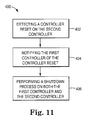
- FIG. 11 one exemplary embodiment of a method of handing controller resets in a multiple, redundant controller system according to the present invention is shown generally at 400 .
- the redundant controller system includes first controller 112 and second controller 114 actively connected and operating as a mirrored pair and at 402 , a reset condition is detected on the second controller 114 .
- the second controller 114 is reset and begins a shutdown process.
- the shutdown process includes notifying the first controller 112 of the controller reset via a communications link between the first controller 112 and the second controller 114 .
- the first controller is notified of the reset occurring on the second controller via mirror bus 200 .
- a shutdown process is performed on both the first controller 112 and the second controller 114 . As such, both the first controller 112 and the second controller 114 go through a shutdown process at the same time.
- FIG. 12 a diagram further illustrating one exemplary embodiment of a method of resetting a controller in a dual controller system according to the present invention is generally shown at 410 .
- the first controller 112 and the second controller 114 are powered-up. The shutdown flushes all internal buffers and parks the memories.
- the first controller and the second controller are reset.
- the mirror bus 200 interface between the first controller 112 and the second controller 114 is disabled.
- the act of resetting the first controller 112 and the second controller 114 causes disabling of the mirror bus 200 .
- the act of disabling the mirror bus prevents further propagation of resets between boards from occurring until the mirror bus is re-enabled.
- each controller, first controller 112 and second controller 114 perform a self-test.
- the self-test typically includes testing the microprocessor subsystem and SDRAM memory as previously described in this application, as well as testing internal memory controller ASICs 122 and 162 and all data path busses.
- the mirror bus 200 interface between first controller 112 and second controller 114 remains disabled. As such, any resets or interrupts that may occur due to one of the controllers, or as a result of a self-test, does not affect the other controller.
- the controller on which the unsuccessful self-test exists enters a recovery mode at 422 .
- the recovery mode includes generating an error to the host computer system informing it of the failure and removing the “bad” controller from use in the array. The remaining “good” controller will then start operation in a single controller mode where mirroring of data is not necessary.
- the mirror bus 200 interface between the first controller 112 and the second controller 114 is enabled. As such, the first controller 112 and second controller 114 have verified that the reset or cause of the reset has been cleared and they may again continue to operate as a mirrored pair.
- the above method of handling controller resets using the redundant controller system provides for localization of resets on one controller such that the resets are not able to propagate to a second controller unless enabled along with the mirroring bus. This provides the benefits of hardware management of reset synchronization between multiple controller boards while still enabling a method for the system firmware to disable a controller from being allowed to reset all controllers in the system.
- Known processes for on-line removal of a controller from a redundant controller system includes an early warning switch or short connector pin which provides a warning to the redundant controller system that a controller is being removed.
- the warning causes the controller to finish the controller's current memory access, and then place the controller's non-volatile memory into a self-refresh mode.
- the other “paired” controller is allowed to resume operation for controlling the redundant controller system.
- partially removed controllers can hold a system inactive until the detection pin entirely breaks contact. This setup provides an opportunity for an incorrect procedure, such as the controller being only “partially removed” from the redundant controller system, to extend the online removal downtime passed the host operating systems time-out period.
- FIG. 13 is a diagram illustrating one exemplary embodiment of a method of on-line removal of a controller from a redundant controller system according to the present invention.
- the method is shown generally at 450 .
- the on-line removal method 450 provides for safe on-line removal of a controller from a redundant controller system, while minimizing redundant controller system downtime.
- an early warning switch or short pin on a connector provides a warning to the system 110 that a controller is being removed as such, preferably the detection occurs prior to total disconnection of the controller from the redundant controller system 110 .
- the warning is received via hot plug warning 142 or hot plug warning 182 .
- first controller 112 is removed from the redundant controller system 110 .
- a shutdown sequence is performed on the first controller 112 and the second controller 114 .
- the shutdown sequence for each controller includes interrupting the controller's processor, and allowing the processor to finish its active processing tasks.
- the shutdown sequence for each controller further includes completing outstanding memory accesses to memory 120 and memory 160 , and flushing of internal buffers.
- the memory controller 122 writes a status word to memory 120
- memory controller 162 writes a status word to memory 160 .
- first memory 120 and second memory 160 have a self-refresh mode, and more preferably include a battery back-up.
- the first memory 120 and the second memory 160 are placed into a self-refresh mode by their corresponding memory controller, the first memory controller 122 and the second memory controller 162 .
- the controller detecting removal stays off-line waiting for removal to finish. Its memory stays in a self-refresh mode.
- the controller not detecting removal immediately starts the process of coming on-line.
- first controller 112 detecting removal stays off-line waiting for removal to finish and memory 120 stays in a self-refresh mode (in one aspect, the memory is battery backed DRAM).
- the second controller 114 not detecting removal immediately starts the process of coming on-line, minimizing downtime of the redundant controller system.
- the memory 160 e.g., a battery backed DRAM is brought out of the self-refresh mode, and has retained the previously written status word for use by the memory controller.
Abstract
Description
Claims (17)
Priority Applications (3)
| Application Number | Priority Date | Filing Date | Title |
|---|---|---|---|
| US09/810,108 US6708285B2 (en) | 2001-03-15 | 2001-03-15 | Redundant controller data storage system having system and method for handling controller resets |
| GB0205555A GB2375412B (en) | 2001-03-15 | 2002-03-08 | Redundant controller data storage system having system and method for handling controller resets |
| JP2002072619A JP2002358210A (en) | 2001-03-15 | 2002-03-15 | Redundant controller data storage system having system and method for handling controller reset |
Applications Claiming Priority (1)
| Application Number | Priority Date | Filing Date | Title |
|---|---|---|---|
| US09/810,108 US6708285B2 (en) | 2001-03-15 | 2001-03-15 | Redundant controller data storage system having system and method for handling controller resets |
Publications (2)
| Publication Number | Publication Date |
|---|---|
| US20020133740A1 US20020133740A1 (en) | 2002-09-19 |
| US6708285B2 true US6708285B2 (en) | 2004-03-16 |
Family
ID=25203018
Family Applications (1)
| Application Number | Title | Priority Date | Filing Date |
|---|---|---|---|
| US09/810,108 Expired - Fee Related US6708285B2 (en) | 2001-03-15 | 2001-03-15 | Redundant controller data storage system having system and method for handling controller resets |
Country Status (3)
| Country | Link |
|---|---|
| US (1) | US6708285B2 (en) |
| JP (1) | JP2002358210A (en) |
| GB (1) | GB2375412B (en) |
Cited By (33)
| Publication number | Priority date | Publication date | Assignee | Title |
|---|---|---|---|---|
| US5910915A (en) * | 1992-01-14 | 1999-06-08 | Sandisk Corporation | EEPROM with split gate source side injection |
| US20030101228A1 (en) * | 2001-11-02 | 2003-05-29 | Busser Richard W. | Data mirroring between controllers in an active-active controller pair |
| US20030212860A1 (en) * | 2002-03-01 | 2003-11-13 | Hitachi, Ltd. | System and method for storage system |
| US20040015491A1 (en) * | 2000-05-29 | 2004-01-22 | Brown Craig Matthew | Method for enabling file format compatibility |
| US20040133752A1 (en) * | 2002-12-18 | 2004-07-08 | Hitachi, Ltd. | Method for controlling storage device controller, storage device controller, and program |
| US20040153749A1 (en) * | 2002-12-02 | 2004-08-05 | Schwarm Stephen C. | Redundant multi-processor and logical processor configuration for a file server |
| US20050160243A1 (en) * | 2001-06-01 | 2005-07-21 | Lubbers Clark E. | Point in time storage copy |
| US20050203874A1 (en) * | 2001-10-22 | 2005-09-15 | Lubbers Clark E. | Multi-controller data processing |
| US20050229021A1 (en) * | 2002-03-28 | 2005-10-13 | Clark Lubbers | Automatic site failover |
| US20050243611A1 (en) * | 2002-03-26 | 2005-11-03 | Clark Lubbers | Flexible data replication mechanism |
| US20050262298A1 (en) * | 2002-03-26 | 2005-11-24 | Clark Lubbers | System and method for ensuring merge completion in a storage area network |
| US20060020754A1 (en) * | 2004-07-21 | 2006-01-26 | Susumu Suzuki | Storage system |
| US6996655B1 (en) * | 2001-12-21 | 2006-02-07 | Cypress Semiconductor Corp. | Efficient peer-to-peer DMA |
| US20060150005A1 (en) * | 2004-12-21 | 2006-07-06 | Nec Corporation | Fault tolerant computer system and interrupt control method for the same |
| US20060168403A1 (en) * | 2005-01-27 | 2006-07-27 | Curt Kolovson | Intelligent cache management |
| US20060171055A1 (en) * | 2005-01-31 | 2006-08-03 | Ballard Curtis C | Recording errors in tape drives |
| US20060176096A1 (en) * | 2005-02-10 | 2006-08-10 | International Business Machines Corporation | Power supply insensitive delay element |
| US20060230243A1 (en) * | 2005-04-06 | 2006-10-12 | Robert Cochran | Cascaded snapshots |
| US20070022263A1 (en) * | 2005-07-22 | 2007-01-25 | John Fandel | Data synchronization management |
| US20070025008A1 (en) * | 2005-07-27 | 2007-02-01 | Ballard Curtis C | Tape drive error management |
| US7197519B2 (en) | 2002-11-14 | 2007-03-27 | Hitachi, Ltd. | Database system including center server and local servers |
| US20070094393A1 (en) * | 2005-10-24 | 2007-04-26 | Cochran Robert A | Intelligent logical unit provisioning |
| US7325078B2 (en) | 2005-10-06 | 2008-01-29 | Hewlett-Packard Development Company, L.P. | Secure data scrubbing |
| US7353353B2 (en) | 2001-01-17 | 2008-04-01 | Hewlett-Packard Development Company, L.P. | File security management |
| US20080129325A1 (en) * | 2005-02-10 | 2008-06-05 | International Business Machines Corporation | On-chip detection of power supply vulnerabilities |
| US20080178188A1 (en) * | 2007-01-19 | 2008-07-24 | Thomas Cooke | Critical resource management |
| US20080215806A1 (en) * | 2007-03-01 | 2008-09-04 | Feather Stanley S | Access control management |
| US20080212222A1 (en) * | 2007-03-01 | 2008-09-04 | Stan Feather | Access control management |
| US7467268B2 (en) | 2006-04-14 | 2008-12-16 | Hewlett-Packard Development Company, L.P. | Concurrent data restore and background copy operations in storage networks |
| US7694079B2 (en) | 2007-04-04 | 2010-04-06 | Hewlett-Packard Development Company, L.P. | Tagged sequential read operations |
| US20110208912A1 (en) * | 2010-02-22 | 2011-08-25 | International Business Machines Corporation | Full-stripe-write protocol for maintaining parity coherency in a write-back distributed redundancy data storage system |
| TWI579688B (en) * | 2012-02-29 | 2017-04-21 | 萬國商業機器公司 | Raid data storage system |
| US11109017B2 (en) | 2018-09-12 | 2021-08-31 | Semiconductor Components Industries, Llc | Systems and methods for fault detection in image sensor processors |
Families Citing this family (24)
| Publication number | Priority date | Publication date | Assignee | Title |
|---|---|---|---|---|
| JP4060552B2 (en) * | 2001-08-06 | 2008-03-12 | 株式会社日立製作所 | Storage device system and storage device system configuration method |
| US7499410B2 (en) | 2001-12-26 | 2009-03-03 | Cisco Technology, Inc. | Fibre channel switch that enables end devices in different fabrics to communicate with one another while retaining their unique fibre channel domain—IDs |
| US7616637B1 (en) | 2002-04-01 | 2009-11-10 | Cisco Technology, Inc. | Label switching in fibre channel networks |
| US7206288B2 (en) * | 2002-06-12 | 2007-04-17 | Cisco Technology, Inc. | Methods and apparatus for characterizing a route in fibre channel fabric |
| US7433326B2 (en) * | 2002-11-27 | 2008-10-07 | Cisco Technology, Inc. | Methods and devices for exchanging peer parameters between network devices |
| JP2004302713A (en) * | 2003-03-31 | 2004-10-28 | Hitachi Ltd | Storage system and its control method |
| US7437425B2 (en) * | 2003-09-30 | 2008-10-14 | Emc Corporation | Data storage system having shared resource |
| US7024328B2 (en) * | 2004-01-27 | 2006-04-04 | Lsi Logic Corporation | Systems and methods for non-intrusive testing of signals between circuits |
| US7290170B2 (en) * | 2004-04-07 | 2007-10-30 | International Business Machines Corporation | Arbitration method and system for redundant controllers, with output interlock and automatic switching capabilities |
| US20060083102A1 (en) * | 2004-10-20 | 2006-04-20 | Seagate Technology Llc | Failover control of dual controllers in a redundant data storage system |
| US7593324B2 (en) * | 2004-10-25 | 2009-09-22 | Cisco Technology, Inc. | Graceful port shutdown protocol for fibre channel interfaces |
| US7916628B2 (en) * | 2004-11-01 | 2011-03-29 | Cisco Technology, Inc. | Trunking for fabric ports in fibre channel switches and attached devices |
| US7649844B2 (en) | 2004-12-29 | 2010-01-19 | Cisco Technology, Inc. | In-order fibre channel packet delivery |
| ITMI20050063A1 (en) | 2005-01-20 | 2006-07-21 | Atmel Corp | METHOD AND SYSTEM FOR THE MANAGEMENT OF A SUSPENSION REQUEST IN A FLASH MEMORY |
| US7590885B2 (en) * | 2005-04-26 | 2009-09-15 | Hewlett-Packard Development Company, L.P. | Method and system of copying memory from a source processor to a target processor by duplicating memory writes |
| US7549029B2 (en) * | 2005-05-06 | 2009-06-16 | International Business Machines Corporation | Methods for creating hierarchical copies |
| US7882479B2 (en) * | 2007-06-06 | 2011-02-01 | International Business Machines Corporation | Method and apparatus for implementing redundant memory access using multiple controllers on the same bank of memory |
| US7725762B2 (en) * | 2007-06-06 | 2010-05-25 | International Business Machines Corporation | Implementing redundant memory access using multiple controllers on the same bank of memory |
| US9055044B2 (en) * | 2012-12-03 | 2015-06-09 | Hitachi, Ltd. | Computer system and method of controlling computer system |
| US10031820B2 (en) * | 2013-01-17 | 2018-07-24 | Lenovo Enterprise Solutions (Singapore) Pte. Ltd. | Mirroring high performance and high availablity applications across server computers |
| US9606944B2 (en) | 2014-03-20 | 2017-03-28 | International Business Machines Corporation | System and method for computer memory with linked paths |
| JP2021026375A (en) * | 2019-08-01 | 2021-02-22 | 株式会社日立製作所 | Storage system |
| JP7145902B2 (en) * | 2020-03-04 | 2022-10-03 | 株式会社日立製作所 | Storage system and its control method |
| CN111708329A (en) * | 2020-05-18 | 2020-09-25 | 武汉华中数控股份有限公司 | Intelligent numerical control system and method |
Citations (39)
| Publication number | Priority date | Publication date | Assignee | Title |
|---|---|---|---|---|
| US4958273A (en) | 1987-08-26 | 1990-09-18 | International Business Machines Corporation | Multiprocessor system architecture with high availability |
| US5155835A (en) | 1990-11-19 | 1992-10-13 | Storage Technology Corporation | Multilevel, hierarchical, dynamically mapped data storage subsystem |
| US5155845A (en) | 1990-06-15 | 1992-10-13 | Storage Technology Corporation | Data storage system for providing redundant copies of data on different disk drives |
| JPH04364514A (en) | 1991-06-11 | 1992-12-16 | Mitsubishi Electric Corp | Dual-port disk controller |
| US5193154A (en) | 1987-07-10 | 1993-03-09 | Hitachi, Ltd. | Buffered peripheral system and method for backing up and retrieving data to and from backup memory device |
| US5195100A (en) | 1990-03-02 | 1993-03-16 | Micro Technology, Inc. | Non-volatile memory storage of write operation identifier in data sotrage device |
| US5204952A (en) | 1988-07-18 | 1993-04-20 | Northern Telecom Limited | Duplex processor arrangement for a switching system |
| US5212784A (en) | 1990-10-22 | 1993-05-18 | Delphi Data, A Division Of Sparks Industries, Inc. | Automated concurrent data backup system |
| US5212785A (en) | 1990-04-06 | 1993-05-18 | Micro Technology, Inc. | Apparatus and method for controlling data flow between a computer and memory devices |
| US5226151A (en) | 1989-10-17 | 1993-07-06 | Fujitsu Limited | Emergency resumption processing apparatus for an information processing system |
| US5237658A (en) | 1991-10-01 | 1993-08-17 | Tandem Computers Incorporated | Linear and orthogonal expansion of array storage in multiprocessor computing systems |
| US5274645A (en) | 1990-03-02 | 1993-12-28 | Micro Technology, Inc. | Disk array system |
| US5278838A (en) | 1991-06-18 | 1994-01-11 | Ibm Corp. | Recovery from errors in a redundant array of disk drives |
| US5287462A (en) | 1991-12-20 | 1994-02-15 | Ncr Corporation | Bufferless SCSI to SCSI data transfer scheme for disk array applications |
| US5289418A (en) | 1992-02-14 | 1994-02-22 | Extended Systems, Inc. | Memory apparatus with built-in parity generation |
| US5291494A (en) | 1989-08-01 | 1994-03-01 | Digital Equipment Corporation | Method of handling errors in software |
| US5297258A (en) | 1991-11-21 | 1994-03-22 | Ast Research, Inc. | Data logging for hard disk data storage systems |
| US5361347A (en) | 1990-04-06 | 1994-11-01 | Mti Technology Corporation | Resource management in a multiple resource system where each resource includes an availability state stored in a memory of the resource |
| US5379415A (en) | 1992-09-29 | 1995-01-03 | Zitel Corporation | Fault tolerant memory system |
| US5388254A (en) | 1992-03-27 | 1995-02-07 | International Business Machines Corporation | Method and means for limiting duration of input/output (I/O) requests |
| US5418921A (en) | 1992-05-05 | 1995-05-23 | International Business Machines Corporation | Method and means for fast writing data to LRU cached based DASD arrays under diverse fault tolerant modes |
| US5437022A (en) | 1992-12-17 | 1995-07-25 | International Business Machines Corporation | Storage controller having additional cache memory and a means for recovering from failure and reconfiguring a control unit thereof in response thereto |
| US5459857A (en) | 1992-05-15 | 1995-10-17 | Storage Technology Corporation | Fault tolerant disk array data storage subsystem |
| US5495570A (en) | 1991-07-18 | 1996-02-27 | Tandem Computers Incorporated | Mirrored memory multi-processor system |
| US5546539A (en) | 1993-12-29 | 1996-08-13 | Intel Corporation | Method and system for updating files of a plurality of storage devices through propogation of files over a nework |
| US5553230A (en) | 1995-01-18 | 1996-09-03 | Hewlett-Packard Company | Identifying controller pairs in a dual controller disk array |
| US5568641A (en) | 1995-01-18 | 1996-10-22 | Hewlett-Packard Company | Powerfail durable flash EEPROM upgrade |
| US5574863A (en) | 1994-10-25 | 1996-11-12 | Hewlett-Packard Company | System for using mirrored memory as a robust communication path between dual disk storage controllers |
| US5666512A (en) | 1995-02-10 | 1997-09-09 | Hewlett-Packard Company | Disk array having hot spare resources and methods for using hot spare resources to store user data |
| US5682471A (en) | 1994-10-06 | 1997-10-28 | Billings; Thomas Neal | System for transparently storing inputs to non-volatile storage and automatically re-entering them to reconstruct work if volatile memory is lost |
| US5699510A (en) | 1994-12-15 | 1997-12-16 | Hewlett-Packard Company | Failure detection system for a mirrored memory dual controller disk storage system |
| US5856989A (en) | 1996-08-13 | 1999-01-05 | Hewlett-Packard Company | Method and apparatus for parity block generation |
| US5915082A (en) * | 1996-06-07 | 1999-06-22 | Lockheed Martin Corporation | Error detection and fault isolation for lockstep processor systems |
| US5928367A (en) | 1995-01-06 | 1999-07-27 | Hewlett-Packard Company | Mirrored memory dual controller disk storage system |
| US5960451A (en) | 1997-09-16 | 1999-09-28 | Hewlett-Packard Company | System and method for reporting available capacity in a data storage system with variable consumption characteristics |
| US6085332A (en) | 1998-08-07 | 2000-07-04 | Mylex Corporation | Reset design for redundant raid controllers |
| US6092168A (en) | 1996-10-25 | 2000-07-18 | Hewlett-Packard Co. | Data storage system and method for deallocating space by writing and detecting a predefined data pattern |
| US6138247A (en) * | 1998-05-14 | 2000-10-24 | Motorola, Inc. | Method for switching between multiple system processors |
| US6327675B1 (en) * | 1998-07-31 | 2001-12-04 | Nortel Networks Limited | Fault tolerant system and method |
-
2001
- 2001-03-15 US US09/810,108 patent/US6708285B2/en not_active Expired - Fee Related
-
2002
- 2002-03-08 GB GB0205555A patent/GB2375412B/en not_active Expired - Fee Related
- 2002-03-15 JP JP2002072619A patent/JP2002358210A/en not_active Withdrawn
Patent Citations (39)
| Publication number | Priority date | Publication date | Assignee | Title |
|---|---|---|---|---|
| US5193154A (en) | 1987-07-10 | 1993-03-09 | Hitachi, Ltd. | Buffered peripheral system and method for backing up and retrieving data to and from backup memory device |
| US4958273A (en) | 1987-08-26 | 1990-09-18 | International Business Machines Corporation | Multiprocessor system architecture with high availability |
| US5204952A (en) | 1988-07-18 | 1993-04-20 | Northern Telecom Limited | Duplex processor arrangement for a switching system |
| US5291494A (en) | 1989-08-01 | 1994-03-01 | Digital Equipment Corporation | Method of handling errors in software |
| US5226151A (en) | 1989-10-17 | 1993-07-06 | Fujitsu Limited | Emergency resumption processing apparatus for an information processing system |
| US5195100A (en) | 1990-03-02 | 1993-03-16 | Micro Technology, Inc. | Non-volatile memory storage of write operation identifier in data sotrage device |
| US5274645A (en) | 1990-03-02 | 1993-12-28 | Micro Technology, Inc. | Disk array system |
| US5212785A (en) | 1990-04-06 | 1993-05-18 | Micro Technology, Inc. | Apparatus and method for controlling data flow between a computer and memory devices |
| US5361347A (en) | 1990-04-06 | 1994-11-01 | Mti Technology Corporation | Resource management in a multiple resource system where each resource includes an availability state stored in a memory of the resource |
| US5155845A (en) | 1990-06-15 | 1992-10-13 | Storage Technology Corporation | Data storage system for providing redundant copies of data on different disk drives |
| US5212784A (en) | 1990-10-22 | 1993-05-18 | Delphi Data, A Division Of Sparks Industries, Inc. | Automated concurrent data backup system |
| US5155835A (en) | 1990-11-19 | 1992-10-13 | Storage Technology Corporation | Multilevel, hierarchical, dynamically mapped data storage subsystem |
| JPH04364514A (en) | 1991-06-11 | 1992-12-16 | Mitsubishi Electric Corp | Dual-port disk controller |
| US5278838A (en) | 1991-06-18 | 1994-01-11 | Ibm Corp. | Recovery from errors in a redundant array of disk drives |
| US5495570A (en) | 1991-07-18 | 1996-02-27 | Tandem Computers Incorporated | Mirrored memory multi-processor system |
| US5237658A (en) | 1991-10-01 | 1993-08-17 | Tandem Computers Incorporated | Linear and orthogonal expansion of array storage in multiprocessor computing systems |
| US5297258A (en) | 1991-11-21 | 1994-03-22 | Ast Research, Inc. | Data logging for hard disk data storage systems |
| US5287462A (en) | 1991-12-20 | 1994-02-15 | Ncr Corporation | Bufferless SCSI to SCSI data transfer scheme for disk array applications |
| US5289418A (en) | 1992-02-14 | 1994-02-22 | Extended Systems, Inc. | Memory apparatus with built-in parity generation |
| US5388254A (en) | 1992-03-27 | 1995-02-07 | International Business Machines Corporation | Method and means for limiting duration of input/output (I/O) requests |
| US5418921A (en) | 1992-05-05 | 1995-05-23 | International Business Machines Corporation | Method and means for fast writing data to LRU cached based DASD arrays under diverse fault tolerant modes |
| US5459857A (en) | 1992-05-15 | 1995-10-17 | Storage Technology Corporation | Fault tolerant disk array data storage subsystem |
| US5379415A (en) | 1992-09-29 | 1995-01-03 | Zitel Corporation | Fault tolerant memory system |
| US5437022A (en) | 1992-12-17 | 1995-07-25 | International Business Machines Corporation | Storage controller having additional cache memory and a means for recovering from failure and reconfiguring a control unit thereof in response thereto |
| US5546539A (en) | 1993-12-29 | 1996-08-13 | Intel Corporation | Method and system for updating files of a plurality of storage devices through propogation of files over a nework |
| US5682471A (en) | 1994-10-06 | 1997-10-28 | Billings; Thomas Neal | System for transparently storing inputs to non-volatile storage and automatically re-entering them to reconstruct work if volatile memory is lost |
| US5574863A (en) | 1994-10-25 | 1996-11-12 | Hewlett-Packard Company | System for using mirrored memory as a robust communication path between dual disk storage controllers |
| US5699510A (en) | 1994-12-15 | 1997-12-16 | Hewlett-Packard Company | Failure detection system for a mirrored memory dual controller disk storage system |
| US5928367A (en) | 1995-01-06 | 1999-07-27 | Hewlett-Packard Company | Mirrored memory dual controller disk storage system |
| US5553230A (en) | 1995-01-18 | 1996-09-03 | Hewlett-Packard Company | Identifying controller pairs in a dual controller disk array |
| US5568641A (en) | 1995-01-18 | 1996-10-22 | Hewlett-Packard Company | Powerfail durable flash EEPROM upgrade |
| US5666512A (en) | 1995-02-10 | 1997-09-09 | Hewlett-Packard Company | Disk array having hot spare resources and methods for using hot spare resources to store user data |
| US5915082A (en) * | 1996-06-07 | 1999-06-22 | Lockheed Martin Corporation | Error detection and fault isolation for lockstep processor systems |
| US5856989A (en) | 1996-08-13 | 1999-01-05 | Hewlett-Packard Company | Method and apparatus for parity block generation |
| US6092168A (en) | 1996-10-25 | 2000-07-18 | Hewlett-Packard Co. | Data storage system and method for deallocating space by writing and detecting a predefined data pattern |
| US5960451A (en) | 1997-09-16 | 1999-09-28 | Hewlett-Packard Company | System and method for reporting available capacity in a data storage system with variable consumption characteristics |
| US6138247A (en) * | 1998-05-14 | 2000-10-24 | Motorola, Inc. | Method for switching between multiple system processors |
| US6327675B1 (en) * | 1998-07-31 | 2001-12-04 | Nortel Networks Limited | Fault tolerant system and method |
| US6085332A (en) | 1998-08-07 | 2000-07-04 | Mylex Corporation | Reset design for redundant raid controllers |
Cited By (72)
| Publication number | Priority date | Publication date | Assignee | Title |
|---|---|---|---|---|
| US5910915A (en) * | 1992-01-14 | 1999-06-08 | Sandisk Corporation | EEPROM with split gate source side injection |
| US20040015491A1 (en) * | 2000-05-29 | 2004-01-22 | Brown Craig Matthew | Method for enabling file format compatibility |
| US7353353B2 (en) | 2001-01-17 | 2008-04-01 | Hewlett-Packard Development Company, L.P. | File security management |
| US7290102B2 (en) | 2001-06-01 | 2007-10-30 | Hewlett-Packard Development Company, L.P. | Point in time storage copy |
| US20050160243A1 (en) * | 2001-06-01 | 2005-07-21 | Lubbers Clark E. | Point in time storage copy |
| US7478215B2 (en) | 2001-10-22 | 2009-01-13 | Hewlett-Packard Development Company, L.P. | Multi-controller write operations |
| US20050203874A1 (en) * | 2001-10-22 | 2005-09-15 | Lubbers Clark E. | Multi-controller data processing |
| US20030101228A1 (en) * | 2001-11-02 | 2003-05-29 | Busser Richard W. | Data mirroring between controllers in an active-active controller pair |
| US7107320B2 (en) * | 2001-11-02 | 2006-09-12 | Dot Hill Systems Corp. | Data mirroring between controllers in an active-active controller pair |
| US6996655B1 (en) * | 2001-12-21 | 2006-02-07 | Cypress Semiconductor Corp. | Efficient peer-to-peer DMA |
| US7596660B2 (en) | 2002-03-01 | 2009-09-29 | Hitachi, Ltd. | System and method for storage system |
| US6985997B2 (en) * | 2002-03-01 | 2006-01-10 | Hitachi, Ltd. | System and method for storage system |
| US20060020755A1 (en) * | 2002-03-01 | 2006-01-26 | Hitachi, Ltd. | System and method for storage system |
| US20030212860A1 (en) * | 2002-03-01 | 2003-11-13 | Hitachi, Ltd. | System and method for storage system |
| US20070136527A1 (en) * | 2002-03-01 | 2007-06-14 | Hitachi, Ltd. | System and method for storage system |
| US7181571B2 (en) | 2002-03-01 | 2007-02-20 | Hitachi, Ltd. | System and method for storage system |
| US20050262298A1 (en) * | 2002-03-26 | 2005-11-24 | Clark Lubbers | System and method for ensuring merge completion in a storage area network |
| US20050243611A1 (en) * | 2002-03-26 | 2005-11-03 | Clark Lubbers | Flexible data replication mechanism |
| US7137032B2 (en) | 2002-03-26 | 2006-11-14 | Hewlett-Packard Development Company, L.P. | System and method for ensuring merge completion in a storage area network |
| US7542987B2 (en) | 2002-03-28 | 2009-06-02 | Hewlett-Packard Development Company, L.P. | Automatic site failover |
| US20050229021A1 (en) * | 2002-03-28 | 2005-10-13 | Clark Lubbers | Automatic site failover |
| US7693879B2 (en) | 2002-11-14 | 2010-04-06 | Hitachi, Ltd. | Database system including center server and local servers |
| US7197519B2 (en) | 2002-11-14 | 2007-03-27 | Hitachi, Ltd. | Database system including center server and local servers |
| US20070143362A1 (en) * | 2002-11-14 | 2007-06-21 | Norifumi Nishikawa | Database system including center server and local servers |
| US20040153749A1 (en) * | 2002-12-02 | 2004-08-05 | Schwarm Stephen C. | Redundant multi-processor and logical processor configuration for a file server |
| US7028218B2 (en) * | 2002-12-02 | 2006-04-11 | Emc Corporation | Redundant multi-processor and logical processor configuration for a file server |
| US20040133752A1 (en) * | 2002-12-18 | 2004-07-08 | Hitachi, Ltd. | Method for controlling storage device controller, storage device controller, and program |
| US20050251636A1 (en) * | 2002-12-18 | 2005-11-10 | Hitachi, Ltd. | Method for controlling storage device controller, storage device controller, and program |
| US20070028066A1 (en) * | 2002-12-18 | 2007-02-01 | Hitachi, Ltd. | Method for controlling storage device controller, storage device controller, and program |
| US7962712B2 (en) | 2002-12-18 | 2011-06-14 | Hitachi, Ltd. | Method for controlling storage device controller, storage device controller, and program |
| US7418563B2 (en) | 2002-12-18 | 2008-08-26 | Hitachi, Ltd. | Method for controlling storage device controller, storage device controller, and program |
| US7334097B2 (en) | 2002-12-18 | 2008-02-19 | Hitachi, Ltd. | Method for controlling storage device controller, storage device controller, and program |
| US7093087B2 (en) | 2002-12-18 | 2006-08-15 | Hitachi, Ltd. | Method for controlling storage device controller, storage device controller, and program |
| US7089386B2 (en) | 2002-12-18 | 2006-08-08 | Hitachi, Ltd. | Method for controlling storage device controller, storage device controller, and program |
| US20060168412A1 (en) * | 2002-12-18 | 2006-07-27 | Hitachi, Ltd. | Method for controlling storage device controller, storage device controller, and program |
| US20080288733A1 (en) * | 2002-12-18 | 2008-11-20 | Susumu Suzuki | Method for controlling storage device controller, storage device controller, and program |
| US7243116B2 (en) | 2004-07-21 | 2007-07-10 | Hitachi, Ltd. | Storage system |
| US20060020754A1 (en) * | 2004-07-21 | 2006-01-26 | Susumu Suzuki | Storage system |
| US7523148B2 (en) | 2004-07-21 | 2009-04-21 | Hitachi, Ltd. | Storage system |
| US20060150005A1 (en) * | 2004-12-21 | 2006-07-06 | Nec Corporation | Fault tolerant computer system and interrupt control method for the same |
| US7441150B2 (en) * | 2004-12-21 | 2008-10-21 | Nec Corporation | Fault tolerant computer system and interrupt control method for the same |
| US8127088B2 (en) | 2005-01-27 | 2012-02-28 | Hewlett-Packard Development Company, L.P. | Intelligent cache management |
| US20060168403A1 (en) * | 2005-01-27 | 2006-07-27 | Curt Kolovson | Intelligent cache management |
| US7301718B2 (en) | 2005-01-31 | 2007-11-27 | Hewlett-Packard Development Company, L.P. | Recording errors in tape drives |
| US20060171055A1 (en) * | 2005-01-31 | 2006-08-03 | Ballard Curtis C | Recording errors in tape drives |
| US20100109700A1 (en) * | 2005-02-10 | 2010-05-06 | International Business Machines Corporation | On-chip detection of power supply vulnerabilities |
| US7646208B2 (en) | 2005-02-10 | 2010-01-12 | International Business Machines Corporation | On-chip detection of power supply vulnerabilities |
| US20080129325A1 (en) * | 2005-02-10 | 2008-06-05 | International Business Machines Corporation | On-chip detection of power supply vulnerabilities |
| US20060176096A1 (en) * | 2005-02-10 | 2006-08-10 | International Business Machines Corporation | Power supply insensitive delay element |
| US7952370B2 (en) | 2005-02-10 | 2011-05-31 | International Business Machines Corporation | On-chip detection of power supply vulnerabilities |
| US20060230243A1 (en) * | 2005-04-06 | 2006-10-12 | Robert Cochran | Cascaded snapshots |
| US7779218B2 (en) | 2005-07-22 | 2010-08-17 | Hewlett-Packard Development Company, L.P. | Data synchronization management |
| US20070022263A1 (en) * | 2005-07-22 | 2007-01-25 | John Fandel | Data synchronization management |
| US7206156B2 (en) | 2005-07-27 | 2007-04-17 | Hewlett-Packard Development Company, L.P. | Tape drive error management |
| US20070025008A1 (en) * | 2005-07-27 | 2007-02-01 | Ballard Curtis C | Tape drive error management |
| US7325078B2 (en) | 2005-10-06 | 2008-01-29 | Hewlett-Packard Development Company, L.P. | Secure data scrubbing |
| US7721053B2 (en) | 2005-10-24 | 2010-05-18 | Hewlett-Packard Development Company, L.P. | Intelligent logical unit provisioning |
| US20070094393A1 (en) * | 2005-10-24 | 2007-04-26 | Cochran Robert A | Intelligent logical unit provisioning |
| US7467268B2 (en) | 2006-04-14 | 2008-12-16 | Hewlett-Packard Development Company, L.P. | Concurrent data restore and background copy operations in storage networks |
| US7934027B2 (en) | 2007-01-19 | 2011-04-26 | Hewlett-Packard Development Company, L.P. | Critical resource management |
| US20080178188A1 (en) * | 2007-01-19 | 2008-07-24 | Thomas Cooke | Critical resource management |
| US20080212222A1 (en) * | 2007-03-01 | 2008-09-04 | Stan Feather | Access control management |
| US7861031B2 (en) | 2007-03-01 | 2010-12-28 | Hewlett-Packard Development Company, L.P. | Access control management |
| US20080215806A1 (en) * | 2007-03-01 | 2008-09-04 | Feather Stanley S | Access control management |
| US8024514B2 (en) | 2007-03-01 | 2011-09-20 | Hewlett-Packard Development Company, L.P. | Access control management |
| US7694079B2 (en) | 2007-04-04 | 2010-04-06 | Hewlett-Packard Development Company, L.P. | Tagged sequential read operations |
| US20110208912A1 (en) * | 2010-02-22 | 2011-08-25 | International Business Machines Corporation | Full-stripe-write protocol for maintaining parity coherency in a write-back distributed redundancy data storage system |
| US20120311255A1 (en) * | 2010-02-22 | 2012-12-06 | International Business Machines Corporation | Full-stripe-write protocol for maintaining parity coherency in a write-back distributed redundancy data storage system |
| US8578094B2 (en) * | 2010-02-22 | 2013-11-05 | International Business Machines Corporation | Full-stripe-write protocol for maintaining parity coherency in a write-back distributed redundancy data storage system |
| US8583866B2 (en) * | 2010-02-22 | 2013-11-12 | International Business Machines Corporation | Full-stripe-write protocol for maintaining parity coherency in a write-back distributed redundancy data storage system |
| TWI579688B (en) * | 2012-02-29 | 2017-04-21 | 萬國商業機器公司 | Raid data storage system |
| US11109017B2 (en) | 2018-09-12 | 2021-08-31 | Semiconductor Components Industries, Llc | Systems and methods for fault detection in image sensor processors |
Also Published As
| Publication number | Publication date |
|---|---|
| GB2375412B (en) | 2005-03-23 |
| GB2375412A (en) | 2002-11-13 |
| GB0205555D0 (en) | 2002-04-24 |
| US20020133740A1 (en) | 2002-09-19 |
| JP2002358210A (en) | 2002-12-13 |
Similar Documents
| Publication | Publication Date | Title |
|---|---|---|
| US6708285B2 (en) | Redundant controller data storage system having system and method for handling controller resets | |
| US6802023B2 (en) | Redundant controller data storage system having hot insertion system and method | |
| US6715101B2 (en) | Redundant controller data storage system having an on-line controller removal system and method | |
| JP3732440B2 (en) | Method and apparatus for maintaining consistency of data stored in mirroring devices | |
| JP4275771B2 (en) | Warm swap of mirrored write-back cache module | |
| US5740397A (en) | IDE disk drive adapter for computer backup and fault tolerance | |
| US5574950A (en) | Remote data shadowing using a multimode interface to dynamically reconfigure control link-level and communication link-level | |
| US7549020B2 (en) | Method and apparatus for raid on memory | |
| JP2532317B2 (en) | Backup method of general-purpose I / O redundancy method in process control system | |
| EP1019823B1 (en) | Redundant controller diagnosis using a private lun | |
| US7124244B2 (en) | Storage system and a method of speeding up writing data into the storage system | |
| US20100083040A1 (en) | Expander Circuit For A Solid State Persistent Storage Device That Provides A Plurality Of Interfaces To Corresponding Storage Controllers | |
| US20060010351A1 (en) | Controller capable of self-monitoring, redundant storage system having the same, and method thereof | |
| JP3284963B2 (en) | Disk array control device and control method | |
| US6938188B1 (en) | Method for verifying functional integrity of computer hardware, particularly data storage devices | |
| US6647516B1 (en) | Fault tolerant data storage systems and methods of operating a fault tolerant data storage system | |
| JPH11353129A (en) | Magnetic disk drive capable of having magnetic disk replaced in operation and replacing method for magnetic disk | |
| US6389559B1 (en) | Controller fail-over without device bring-up | |
| JP4669263B2 (en) | Storage device | |
| US7260680B2 (en) | Storage apparatus having microprocessor redundancy for recovery from soft errors | |
| US10248511B2 (en) | Storage system having multiple local and remote volumes and multiple journal volumes using dummy journals for sequence control | |
| JPH1027070A (en) | Data backup system | |
| JP3783560B2 (en) | Information processing system | |
| JP2002351755A (en) | Trouble generating device and testing method for computer system | |
| US20050223122A1 (en) | Integrated circuit capable of remote data storage |
Legal Events
| Date | Code | Title | Description |
|---|---|---|---|
| AS | Assignment |
Owner name: HEWLETT-PACKARD COMPANY, COLORADO Free format text: ASSIGNMENT OF ASSIGNORS INTEREST;ASSIGNORS:OLDFIELD, BARRY J.;JOHANSSON, CHRISTOPHER W.;REEL/FRAME:011844/0236 Effective date: 20010509 |
|
| AS | Assignment |
Owner name: HEWLETT-PACKARD DEVELOPMENT COMPANY L.P., TEXAS Free format text: ASSIGNMENT OF ASSIGNORS INTEREST;ASSIGNOR:HEWLETT-PACKARD COMPANY;REEL/FRAME:014061/0492 Effective date: 20030926 Owner name: HEWLETT-PACKARD DEVELOPMENT COMPANY L.P.,TEXAS Free format text: ASSIGNMENT OF ASSIGNORS INTEREST;ASSIGNOR:HEWLETT-PACKARD COMPANY;REEL/FRAME:014061/0492 Effective date: 20030926 |
|
| FEPP | Fee payment procedure |
Free format text: PAYOR NUMBER ASSIGNED (ORIGINAL EVENT CODE: ASPN); ENTITY STATUS OF PATENT OWNER: LARGE ENTITY |
|
| FPAY | Fee payment |
Year of fee payment: 4 |
|
| REMI | Maintenance fee reminder mailed | ||
| FPAY | Fee payment |
Year of fee payment: 8 |
|
| REMI | Maintenance fee reminder mailed | ||
| AS | Assignment |
Owner name: HEWLETT PACKARD ENTERPRISE DEVELOPMENT LP, TEXAS Free format text: ASSIGNMENT OF ASSIGNORS INTEREST;ASSIGNOR:HEWLETT-PACKARD DEVELOPMENT COMPANY, L.P.;REEL/FRAME:037079/0001 Effective date: 20151027 |
|
| LAPS | Lapse for failure to pay maintenance fees | ||
| STCH | Information on status: patent discontinuation |
Free format text: PATENT EXPIRED DUE TO NONPAYMENT OF MAINTENANCE FEES UNDER 37 CFR 1.362 |
|
| FP | Lapsed due to failure to pay maintenance fee |
Effective date: 20160316 |