US6707829B1 - Enhanced automatic timing adjustment for alternate routing of HFC systems - Google Patents
Enhanced automatic timing adjustment for alternate routing of HFC systems Download PDFInfo
- Publication number
- US6707829B1 US6707829B1 US09/473,344 US47334499A US6707829B1 US 6707829 B1 US6707829 B1 US 6707829B1 US 47334499 A US47334499 A US 47334499A US 6707829 B1 US6707829 B1 US 6707829B1
- Authority
- US
- United States
- Prior art keywords
- communication unit
- signal line
- head
- signal
- sub
- Prior art date
- Legal status (The legal status is an assumption and is not a legal conclusion. Google has not performed a legal analysis and makes no representation as to the accuracy of the status listed.)
- Expired - Lifetime
Links
Images


Classifications
-
- H—ELECTRICITY
- H04—ELECTRIC COMMUNICATION TECHNIQUE
- H04N—PICTORIAL COMMUNICATION, e.g. TELEVISION
- H04N7/00—Television systems
- H04N7/16—Analogue secrecy systems; Analogue subscription systems
- H04N7/173—Analogue secrecy systems; Analogue subscription systems with two-way working, e.g. subscriber sending a programme selection signal
- H04N7/17309—Transmission or handling of upstream communications
-
- H—ELECTRICITY
- H04—ELECTRIC COMMUNICATION TECHNIQUE
- H04J—MULTIPLEX COMMUNICATION
- H04J3/00—Time-division multiplex systems
- H04J3/02—Details
- H04J3/06—Synchronising arrangements
- H04J3/0635—Clock or time synchronisation in a network
- H04J3/0682—Clock or time synchronisation in a network by delay compensation, e.g. by compensation of propagation delay or variations thereof, by ranging
-
- H—ELECTRICITY
- H04—ELECTRIC COMMUNICATION TECHNIQUE
- H04N—PICTORIAL COMMUNICATION, e.g. TELEVISION
- H04N21/00—Selective content distribution, e.g. interactive television or video on demand [VOD]
- H04N21/60—Network structure or processes for video distribution between server and client or between remote clients; Control signalling between clients, server and network components; Transmission of management data between server and client, e.g. sending from server to client commands for recording incoming content stream; Communication details between server and client
- H04N21/61—Network physical structure; Signal processing
- H04N21/6106—Network physical structure; Signal processing specially adapted to the downstream path of the transmission network
- H04N21/6118—Network physical structure; Signal processing specially adapted to the downstream path of the transmission network involving cable transmission, e.g. using a cable modem
-
- H—ELECTRICITY
- H04—ELECTRIC COMMUNICATION TECHNIQUE
- H04N—PICTORIAL COMMUNICATION, e.g. TELEVISION
- H04N21/00—Selective content distribution, e.g. interactive television or video on demand [VOD]
- H04N21/60—Network structure or processes for video distribution between server and client or between remote clients; Control signalling between clients, server and network components; Transmission of management data between server and client, e.g. sending from server to client commands for recording incoming content stream; Communication details between server and client
- H04N21/61—Network physical structure; Signal processing
- H04N21/6156—Network physical structure; Signal processing specially adapted to the upstream path of the transmission network
- H04N21/6168—Network physical structure; Signal processing specially adapted to the upstream path of the transmission network involving cable transmission, e.g. using a cable modem
-
- H—ELECTRICITY
- H04—ELECTRIC COMMUNICATION TECHNIQUE
- H04N—PICTORIAL COMMUNICATION, e.g. TELEVISION
- H04N7/00—Television systems
- H04N7/16—Analogue secrecy systems; Analogue subscription systems
- H04N7/173—Analogue secrecy systems; Analogue subscription systems with two-way working, e.g. subscriber sending a programme selection signal
- H04N2007/17372—Analogue secrecy systems; Analogue subscription systems with two-way working, e.g. subscriber sending a programme selection signal the upstream transmission being initiated or timed by a signal from upstream of the user terminal
Definitions
- This present invention relates in general to wireline communication links, and in particular to timing adjustment of communication signals between multiple subscriber units communicated over a public switch telephone network with a communications network including a hybrid fiber coax (HFC) cable distribution network.
- HFC hybrid fiber coax
- Several cable telephony systems have been proposed for combining telephony, video, and data information over a cable distribution network taking advantage of the existing high bandwidth capabilities of cable television (CATV) operators which have an existing HFC distribution network to subscriber premises that could carry such diverse services.
- CATV cable television
- a single trunk line will service many different individual users.
- a telephony system will often have various trunk lines fanning out from a main control/switching station, and each of these will run from a head-end (control station and switching network) to a service area node. Many different users will be fed to the node and then networked onto the trunk line.
- Trunk lines are typically fiber optic cables which are capable of carrying a tremendous number of calls which carry signals at speeds much greater than conventional metal lines.
- Telephony cable lines whether optic or metal, operate in pairs such that a trunk line will consist of a downstream cable and an upstream cable forming signal line loops for the telephony signal streams to follow.
- Telephony employing cable modem technology combines telephony, video, and data signals over a cable distribution infrastructure.
- the up and downstream cables are installed along the same route and have the same length, although not necessarily installed in the same trench or on the same utility line. However, these main up and downstream lines generally parallel each other.
- a major goal of telephony systems is to supply dependable use to users so that the system may be accessed even during emergencies.
- the system must have a backup transport with an alternate route to ensure that communications continue even if one of the paths is destroyed.
- a line can go down for many reasons including natural forces causing a break in the line, construction digging into the area where a line is laid and breaking the line, maintenance on the line by the operator, and any other number of occurrences.
- operators of telephony systems install redundant trunk lines so that the telephony signal streams may be routed through the redundant trunk lines to form an alternate signal line loop.
- the head-end will route the signal stream through the redundant downstream line while using the upstream line of the main, or signal line loop.
- the redundant upstream line may be used in a similar manner. In fact, any combination of the four lines may be used by the head-end.
- the two main lines (down and upstream) of the signal line loop usually follow the shortest path from the head-end to the service node.
- the redundant lines must follow a different path, often making broad detours resulting in much longer lines than the signal loop lines. Therefore, if a line of the signal line loop is near a construction site, for instance, and capable of being damaged by digging at the site, the redundant line will not be affected since its routing is away from the same area.
- the longer length of the redundant line naturally delays the time that the signal stream will take to go from the head-end to the service node and back. This presents a problem with time based signaling protocols such as time division multiple access (TDMA) protocols. Delaying the time a signal stream takes to go to the service node and back beyond the delay expected as the signal follows the main signal line loop alters the anticipated position of the signal stream and control information within the stream once the signal stream returns to the head-end. Communication links are lost and an adjustment must take place to align the signal stream from the service node to the head-end to a position in the protocol that the head-end will be expecting the signal stream to be in.
- TDMA time division multiple access
- the provision of the time alignment window may facilitate a desirable rate for establishing communications, so as to avoid numerous tries which may result in lost calls during high traffic conditions.
- a method is needed in a telephony system having redundant signal lines to automatically detect when a fault in a signal line loop has occurred, and then automatically compensate for any delays caused by routing the signal stream through the redundant signal line.
- FIG. 1 is a diagram of a communications system in which the present invention may be implemented
- FIG. 2A is a block diagram of components in a cable control unit (CCU) according to the present invention.
- FIG. 2B is a block diagram of components in a cable access unit (CAU) according to the present invention.
- CAU cable access unit
- FIG. 2C is a diagram of a telephony system
- FIG. 3 is a diagram of a system protocol according to an embodiment of the present invention.
- FIG. 4 is a diagram showing a portion of the system protocol of FIG. 3 according to a preferred embodiment of the present invention.
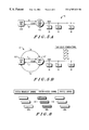
- FIGS. 5A and 5B illustrate the round trip delay and the four combination fiber link paths associated with the HFC communication system
- FIGS. 6A and 6B illustrate the positioning of the short uplink burst (SUB) from the cable access units within a time alignment adjustment window in accordance with the invention
- FIG. 7 shows a representative upstream frame of a carrier from a cable access communication system
- FIG. 8 illustrates the time delay shift of the SUB signals with respect to the communications channels.
- a communications system 10 shows a cable telephone system in block diagram form which employs coaxial cable for standard cable television (CATV) connected to subscriber premises.
- the communication system 10 allows multiple subscribers to access telephony on demand.
- the following description begins with an overview of the communication system 10 , describing the operation of the headend backbone and routers located at the cable company headend, and then the electronics in the cable telephony unit 16 or desktop cable modem 18 which would be located at the subscriber premises, e.g., a home or business 14 .
- a communication system 10 as described employs methods of time division multiplex (TDM) telephony on a cable distribution network 20 for telephony information between multiple subscriber units 16 , 18 communicated over a public switch telephone network (PSTN) 32 with at least one router.
- TDM time division multiplex
- PSTN public switch telephone network
- the communication system 10 is an example of a basic cable backbone architecture which employs a hybrid fiber coax (HFC) cable system using a combination of fiber and coaxial cable to distribute information services to subscriber units at the customer premises.
- HFC hybrid fiber coax
- alternate embodiments of the communication system 10 may incur other suitable communications medium as part of the distribution network.
- TDM time division multiplex
- TDMA time division multiple access
- time slots time division multiplex channels
- TDM delivers data from the headend out to the cable access units, as a constant bit stream, time-slotted for CACS in eight (8) time slots per frame, with each RF carrier being transmitted downstream out to cable access units which can support up to eight (8) simultaneous conversations, where each time slot out of one frame is dedicated to a call.
- the upstream is Time Division Multiple Access (TDMA) from the CAU 16 to allow multiple subscribers to signal into the CCU 12 .
- TDMA Time Division Multiple Access
- the CAU 16 is assigned a time slot, one of eight within a frame, synchronized for data transmission in the upstream path. In a very large cable system however, the system must allow for substantial levels of propagation delay.
- the CAU 16 may be 20 to 200 kilometers away from the headend, and thus propagation delay becomes a significant factor, which delay may also be variable.
- the expected arrival time for all data bursts is equalized for both the cable access unit and the headend, directly relative to the distance over the fiber. Propagation through fiber runs about 60 percent of the speed of light, and thus a factor programmed into the equipment in essence delays everything to align with the expected arrival time of that data.
- a direct fiber that goes from the headend out to the neighborhood e.g., a kilometer away, while the main fiber link is only a kilometer
- another redundant fiber link going to the same neighborhood taking some other branch may be ten (10) kilometers in length to provide two paths to feed the neighborhood.
- the equipment must then be able to compensate very quickly in the case of a fiber cut for propagation delay to prevent calls from being dropped due to transmission delays.
- the system detects the fact that a fiber has been killed or cut and automatically switches over to the alternate fiber and in the process provides a whole new compensation over time, i.e., the delay time with automatic timing adjustment for diverse routing. This significantly facilitates a solution for providing high availability service for telephony in the HFC or cable type of system.
- Communications system 10 is an example of a basic cable system architecture that is a hybrid fiber/coaxial cable (HFC) system using a combination of fiber and coaxial cable to distribute subscriber services to customer premises equipment.
- communications system 10 may consist entirely of coaxial cable, fiber, or other suitable communications medium.
- a cable branch will serve a distribution area shared by a community of subscribers.
- communications system 10 is a cable telephony communications system that provides telephone services along with cable television services on an HFC television infrastructure.
- Communications system 10 includes a cable control unit (CCU) 12 or some other base communications unit that is connected to subscriber 14 by a distribution network 20 and a combiner 22 .
- the CCU is a portion of the equipment at the cable company headend that sends and receives telephone calls to and from the home subscribers.
- Combiner 22 also has an input for video sources 24 .
- CCU 12 also includes cable port transceivers (CPXs) 28 which are connected to combiner 22 . These cable port transceivers generate downstream carrier channels in communications system 10 .
- Downstream or “downlink” as used in this description refers to radio frequency (RF) signals going to the subscriber homes.
- RF radio frequency
- Combiner 22 receives modulated RF carriers from video sources 24 and from CPXs 28 in CCU 12 and sums these signals together to be sent over distribution network 20 .
- CPXs 28 are controlled by a controller 30 which provides all functions necessary to support the data link portion of the system.
- the “data link portion” refers to the ability for the system to carry phone calls in the form of digital data, as well as any other communications in the form of digital data.
- the headend of the communications system typically includes CCU 12 , combiner 22 , and video sources 24 .
- a digital switch may be in a remote location from the headend or may be located at the headend itself. These components are the headend equipment responsible for providing access and management of services to the cable system 10 servicing multiple subscribers.
- the controller 30 of the CCU 12 is connected to the digital switch through carrier facilities, such as T 1 or E 1 , which is connected to the public switching telephone network (PSTN) 32 .
- the digital switch may be, for example, a class 5 TELCO switch.
- Fiber nodes 42 perform directional conversion between the optical domain of fiber optical cable and the electrical domain of coaxial cable in distribution network 20 .
- Each fiber node 42 has a connection to at least one serving area 44 .
- serving area 44 comprises coaxial cable and includes trunk amplifiers 46 , which are bi-directional amplifiers in the depicted example.
- bi-directional line extenders 48 are located near taps 50 which are connected to cable access units (CAUs) 16 located at subscriber 14 . These CAUs are also called “subscriber communications units”.
- CAUs cable access units
- CCU 12 is used to provide telephony (as well as other digital data communications) in communications system 10 . Additionally, CCU 12 controls the cable spectrum, infrastructure resources, and services for all CAUs 16 on a serving area, as well as managing multiple serving areas. CAUs 16 provide telephone and television services at subscriber premises. Typically, a CAU is mounted on the side of the subscriber's home, or on an unintrusive place, such as a basement or attic. The CAU 16 manages the uplink and downlink communications paths and transports cable television channels to the subscriber's television. For example, “A plain old telephone” (POTS) at the subscriber's home plugs into the CAU 16 . The CAU 16 puts the phone signals from the POTS on to the cable system. Additionally, the CAU 16 takes phone calls off the cable system and forwards them to the POTS, as well as taking regular cable TV signals off the cable and passing them along to the subscriber's TV.
- POTS plain old telephone
- upstream burst receiver 202 receives a TDMA burst from a CAU and converts the burst to baseband quadrature I and Q signals.
- a “burst” is a fixed transmission of data in bits bearing information.
- the burst is ⁇ /4-DQPSK modulated.
- These baseband I and Q signals are converted to a digital signal by analog to digital (A/D) converters 204 and 206 and processed by upstream digital signal processor (DSP) 208 .
- A/D converters 204 and 206 are 8-bit A/D converters.
- Upstream DSP 208 sends the processed information to microprocessor 210 .
- Microprocessor 210 sends messages back to the CAU through downstream DSP 212 and downstream TDM transmitter 214 , which is connected to the communications network on which the CAU is located.
- Upstream burst receiver 202 , A/D converters 204 and 206 , upstream DSP 208 , microprocessor 210 , downstream DSP 212 , and downstream transmitter 214 are components found in CPXs 28 in FIG. 1 .
- the downstream components depicted in FIG. 2A may be in the same transceiver or a different transceiver (CPX) from the upstream components illustrated.
- Upstream DSP 208 , microprocessor 210 , and downstream DSP 212 make up a processing unit in FIG. 2 A.
- Microprocessor 210 is found in controller 30 in FIG. 1 . This microprocessor and the DSPs in CPXs 28 form the processing unit in CCU 12 .
- CAU 250 is connected to a hybrid coaxial cable in distribution network 20 in FIG. 1 by RF interfacing and control 252 .
- This interface and control unit provides a 75 ohm interface to the hybrid coaxial cable.
- RF interfacing and control 252 also provides a connection to cable television equipment on the subscriber premises.
- RF interfacing and control 252 includes a control switch to turn on or off signals to premise cable television systems at the subscriber premises.
- Data received from the CCU at RF interfacing and control 252 are sent to digital receiver (demodulator) 254 .
- the signals received from the CCU are in a frequency range from about 50 MHz to 750 MHz and converted to a low intermediate frequency (IF) by digital receiver 254 .
- digital receiver 254 translates the low frequency IF to a baseband ⁇ /4 DPQSK modulated signal.
- the signal is demodulated to obtain bits from the signal.
- data/clock recovery 256 takes the bits from digital receiver 254 and separates the bits to send to processing unit 258 or pulse code modulated (PCM) coder/decoder (codec) 260 .
- PCM pulse code modulated
- codec codec
- Processing unit 258 in the depicted example includes one or more microprocessors or digital signal processors (DSPs) along with random access memory (RAM) and ready only memory (ROM).
- RAM random access memory
- ROM ready only memory
- the RAM and ROM contain data and instructions coding for processes performed by the microprocessors or DSPs within processing unit 258 .
- User information is converted by PCM codec 260 to an analog form and sent to subscriber loop interface (SLIC) 262 .
- SLIC 262 provides basic telephony functions, such as indicating whether the phone is ringing or off hook, or whether loop closure has occurred. Additionally, SLIC 262 separates duplex signals into a send signal and a receive signal. SLIC 262 and the functions performed by it are well known to those who are skilled in the art.
- Ring generator 264 actually provides the voltage used to cause the telephone to ring.
- Transmit data framing 266 takes raw speech data and puts this data into the frame for transmission to the CCU.
- transmit data framing 266 includes the necessary synchronization information and calculates the cyclic redundancy code for error checking, which is placed into the slow channel of the frame (as described in more detail below).
- Transmit data framing 266 is controlled by processing unit 258 and sends signals upstream which are synchronized with the downstream signals.
- This synchronization in transmit data framing 266 is controlled by data/clock recovery 256 .
- data/clock recovery 256 In other words, uplink and downlink transmissions to and from CAU 250 are synchronized.
- the data is transmitted by digital transmitter (modulator) 268 to RF interfacing and control 252 and back to the CCU.
- Data carried across distribution network 20 in FIG. 1 may include both voice and non-voice data, such as ISDN digital video, phone data, interactive video, or interactive multimedia services.
- the transport technology used for the cable telephony exchange service is trunked.
- a cable telephone traffic channel is not dedicated to one particular user, but is available to all users on the basis of a request for service. Such an arrangement is called multiple access or subscriber loop concentration.
- FIG. 2C illustrates how a redundant signal line system in a telephony system 110 may be arranged.
- a signal stream will route from a head-end 120 to a service node 130 through a signal line loop 140 .
- Signal line loop 140 is defined as two signal lines through which a signal stream is routed, one line, or downstream signal line 142 , routing the signal stream from a transmitter 122 in head-end 120 to a receiver 132 of service node 130 .
- a second signal line or upstream signal line 144 is routed from a transmitter 134 of service node 130 to a receiver 124 of head-end 120 .
- An information processor is provided at the head-end 120 of the HFC system 10 for automatically adjusting the timing of the signal stream according to delay parameters determined at the information processor at the head-end 120 .
- the timing adjustment of the signal stream is communicated between the head-end 120 and the communication units, CAUs 16 .
- a number of communication units 152 are coupled to a cable 150 which is then coupled to a combiner/splitter 136 of service node 130 .
- Service node 130 facilitates communication between the number of communication units 152 and the telephony system 110 .
- the number of communication units 152 will be cable access units attached to a user's premise, be it a home or business, which allow the user two-way communication on the cable network.
- telephony cable lines such as those making up signal line loop 140
- the line can be damaged or broken causing loss of telephony service to any user connected to that signal line loop.
- damage to these lines can happen because someone digging in an area is not aware of or careful about the lines, or a natural disaster breaks or damages the line. Failures may also occur in the active fiber optic transmitters and receivers, resulting in loss of service.
- telephony service is considered essential, particularly in times of emergencies, telephony operators build in redundant signal lines. Generally there is a second downstream signal line 146 and a second upstream signal line 148 . These redundant signal lines will not follow the same course as the signal lines of signal line loop 140 .
- head-end 120 will route the signal stream through one or both of the redundant signal lines. For instance, if downstream signal line 142 is damaged, head-end 120 will route the signal stream through second downstream signal line and back up through upstream signal line 144 . Similarly, if upstream signal line 144 is damaged, the upstream path of the signal stream will be through second upstream signal line 148 . If both lines of the signal line loop 140 are damaged, the signal stream routes through second downstream signal line 146 and second upstream signal line 148 . In any of these cases, an alternate signal line loop is formed.
- each of the signal lines 142 , 144 , 146 , and 148 are optic lines made from fiber optics.
- a protocol used for the optic lines is a time division multiplexing (TDM) protocol on the downstream and time division multiple access (TDMA) protocol on the upstream.
- TDM time division multiplexing
- TDMA time division multiple access
- the time through each of the signal lines, or delay time is important.
- the time required for the signal stream to route through one of the lines is determined and dependent upon the length of the signal line.
- the time required for the signal stream to route through signal line 142 will be nearly the same as the time required for the signal stream to route through signal stream 144 since the two lines are installed along the same route and generally the same length, although not required to be so.
- the time through either of the redundant lines, 146 and 148 will be much greater since the lines must follow a detoured route making the optic lines much longer.
- the delay for each of the lines between head-end 120 and user service node 130 in the preferred embodiment is predetermined and stored within head-end 120 .
- the predetermined delay parameters are determined according to the equations:
- d 1 is a length of a first downstream line ( 142 )
- u 1 is a length of a first upstream line ( 144 )
- d 2 is a length of a second downstream line ( 146 )
- u 2 is a length of a second upstream line ( 148 )
- ⁇ d1 is a propagation delay for d 1
- ⁇ d2 is a propagation delay for d 2
- ⁇ u1 is a propagation delay for ul
- ⁇ u2 is a propagation delay for u 2 . Therefore, if one of the signal line loop 140 lines is unusable for signal stream routing, head-end 120 will cycle through the delay parameters until it finds the delay parameter that corresponds to the alternate signal line loop formed by routing the signal stream through one of the redundant lines.
- Head-end 120 must be programmed to automatically detect when one of the lines is unusable, or in other words, when a fault in a line has occurred. If a line goes down, head-end must be able to immediately reroute the signal stream through a redundant line to maintain continuous service to the users. To do so, head-end must be able to detect the fault, preferably independent of the actual rerouting mechanism.
- FIG. 3 graphically shows how head-end 120 detects a fault in the signal lines according to a preferred embodiment of the present invention.
- head-end 120 When a given route of the signal stream is established having an associated delay, head-end 120 will expect a response, or time alignment, from the communication units 152 within a predetermined timing window 202 .
- the response which head-end 120 will be looking for is, in the preferred embodiment, shortened uplink bursts (SUBs) (shown as elements 204 in FIG. 3 indicating that the SUBs may be anywhere within predetermined timing window 202 ) from the communication units 152 .
- predetermined timing window 202 is an access channel 202 of the system protocol 200 as shown in FIG. 3 .
- access channel 202 lies between a system broadcast channel 302 and a traffic channel 304 .
- Head-end 120 detects that the SUBs have shifted into the adjacent channels, whether system broadcast channels (indicated by 306 ) or traffic channels (indicated by 308 ).
- This method of detecting a fault assumes that the head-end receiver can reliably detect that a shift has occurred by detecting the presence of shortened bursts within the adjacent channels. It also assumes that the differential signal line fixed delay is limited to a single slot time. Certainly head-end receivers can be and are designed to recognize short bursts in adjacent channels. Limiting the total fiber round trip differential between any given combination of the signal lines to approximately 60 kilometers maintains any shift in the SUBs to one slot time.
- the active communication units 152 When the downlink signal to the communication units 152 is interrupted requiring a switch to a different signal line during active calls, the active communication units 152 will loose synchronization with the traffic channel 304 at the head-end 120 . The active communication unit 152 will attempt to reconnect by sending the SUBs to the head-end 120 . If the SUBs are within the predetermined timing window 202 , head-end 120 will assign a new time alignment value to the active communication unit 152 and the call will continue.
- head-end 120 If head-end 120 detects that the SUBs are out of bounds, it will begin cycling through the delay parameters, one at a time. For each delay parameter, head-end 120 adjusts receiver 124 of head-end 120 to the predetermined timing window to compensate for the new delay parameter. If the new delay parameter does not correlate with the current alternate signal line loop, the return SUBs from the communication units 152 will not be within predetermined timing window 202 and head-end 120 will cycle to the next delay parameter and adjust to the new delay parameter. Head-end 120 cycles through the delay parameters until the SUBs from communication units 152 are within predetermined timing window 202 .
- head-end 120 will cycle through the delay parameters backwards through the list (relative to the current delay parameter, where the delay parameters are arranged in order of increasing time delay). If the fault occurred in the traffic channel 304 (right of the predetermined timing window 202 ), head-end 120 will cycle forwards through the list If the fault occurred within the predetermined timing window 202 (partially within predetermined timing window 202 and partially outside), then the sign of the fault (positive or negative) will determine which direction head-end will cycle through the delay parameters where positive cycles forward and negative cycles backward.
- head-end 120 Once head-end 120 has selected the delay parameter correlating with the alternate signal line loop, the fault condition will be cleared and the system 10 will stabilize. The timing adjustment is applied to the receiver 124 of head-end 120 .
- the Automatic Timing Adjustment feature provides a capability allowing the CCU 12 to detect timing faults in received RF bursts from CAUs 16 resulting from fault generated fiber path switches, and to automatically compensate for these faults.
- the RF delay in the system 10 has two (2) components which, when summed, cannot exceed the maximum HFC system delay value, e.g., 1.66 msec. These two components as shown in FIG. 5A are an operator-entered delay value and an automatically calculated CAU 16 time alignment value.
- the operator-entered delay value discussed herein is referred to as NR 221 .
- the single NR 221 signal delay has been a static value previously provided by the system operator per the serving area.
- the delay value indicates the delay (in bits) plus a minimum default delay (e.g., 3004 bits) which represents the delay round trip from the CCU 12 to the last fiber node and back to the CCU 12 .
- the CAU 16 time alignment values are dynamically adjusted per CAU 16 when each CAU 16 performs the time alignment procedure (i.e., after each shortened uplink burst on each call, during a ping test).
- the time alignment delay value is sent from the CCU 12 to the CAU 16 and contains a value (e.g., 0-120) indicating the number of bits the CAU 16 needs to subtract from the difference between the reception of a downlink burst and the transmission of an uplink burst
- the system 10 allows provision of a list of four NR 221 delay combinations.
- the CCU 12 automatically selects the best NR 221 delay value following the detection of timing faults in the receive path.
- the CCU 12 will alarm the operator by a critical alarm if a proper timing correction cannot be made.
- the CCU 12 will alarm the operator by a warning that a change in NR 221 delay was made automatically, which should correspond to a fiber switch event.
- the fiber switch detection mechanism relies on at least one CAU 16 sending uplink bursts, received by the CCU 12 outside of the System Access Channel, resulting from any traffic call or maintenance scenario.
- the correction method applies the signal delay adjustment automatically, based on the provisioned list of four possible delays. Specifically, the detection looks for shortened uplink bursts (SUBs) from the CAUs 16 in regions within the SAC channel time slot and the SAC's adjacent time slots. If a SUB is detected by the cable port transceivers (CPXs) outside of the adjustment window of the system access channel, the CPX will report this to the cable port controller (CPC) with the direction of the detection.
- SUBs shortened uplink bursts
- the CPC will pick a next NR 221 value from the list of four in the direction indicated by the CPX as compared with the current delay value.
- the CPC will report that a new NR 221 value has been selected and send a warning that indicates timing adjustments have been made.
- the CPC will send the new NR 221 value to all CPXs 28 in the serving area, where the CPX 28 will change the receive timing window to account for the change in signal delay.
- all CAUs 16 active in a call that can signal in within the adjustment window of the system access channel (SAC) will go through the time alignment procedure and will be allowed to reconnect to the Traffic Channel (TC). However, not until a CAUs 16 signals in outside the adjustment window of the SAC, will the NR 221 signal delay value for the serving area be adjusted. CAUs that reconnected prior to the fiber switch detection will have to attempt another time alignment procedure.
- SAC system access channel
- each of the four delay combinations are sorted from smallest to largest and stored in the CCU 12 .
- CAUs 16 send in shortened uplink bursts (SUBs) on the SAC. These SUBs must be received within a time alignment window on the SAC.
- the CAUs 16 also send in SUBs to reconnect during a call if communication is lost. These SUBs are used to detect redundant fiber switchovers. When a SUB is detected outside the time alignment window a fiber switch is reported. A fiber switch will break the communication link with all of the CAUs 16 . All CAUs 16 active in a call will send in a SUB as part of the reconnect procedure. The SUBs from many CAUs 16 will still be received in the time alignment window if the difference in the fiber length is small. For the CAUs 16 that do make the window, they will go through a reconnect procedure and will be allowed to reconnect to the traffic channel.
- SUBs shortened uplink bursts
- the NR 221 signal delay value for the serving area will be adjusted by choosing another one of the four values.
- the new value will be selected based on whether the SUB is received to the left or right of the adjustment window.
- the current value of NR 221 will be located in the list. If the SUB falls to the left of the window, the next smaller value in the list will be chosen as the new NR 221 . If the SUB falls to the right of the window, the next larger value in the list will be chosen as the new NR 221 .
- the enhanced automatic method will not require the maintenance craftsperson to measure the delay paths.
- SUBs When SUBs are received from CAUs 16 , they will contain an ID which is unique to the CAU 16 , and the CCU 12 will save the bit offset for each CAU 16 . Also, the system will keep track of the bit offsets of the farthest and nearest CAUs 16 .
- a redundant fiber switch is reported.
- NR 221 will be recalculated according to the difference between the old bit offset and the new bit offset
- new_NR 221 old_NR 221 ⁇ (old_bit_offset—new_bit_offset)
- new_NR 221 old_NR 221 +(new_bit_offset—old_bit_offset)
- the NR 221 delay will be set to the smallest possible value.
- the CPX 28 will look for SUBs in all time slots, not just the SAC.
- the NR 221 window will be shifted by the number of bits necessary to get the SUB into the middle of the adjustment window based on a value in the database.
- the database facilitates the calculation of delay parameters corresponding to the alternate signal line loop using the database to adjust the timing of the signal stream.
- ping the nearest CAU 16 If the nearest CAU 16 sends in a SUB with the same bit offset as already recorded, then the new CAU 16 is out of range and the user should be alarmed. If the nearest CAU 16 sends in a SUB with a different bit offset, then an RFS has occurred and NR 221 will be recalculated as described above.
- ping the farthest CAU 16 If the farthest CAU 16 sends in a SUB with the same bit offset as already recorded, then the new CAU 16 is out of range and the user should be alarmed. If the farthest CAU 16 sends in a SUB with a different bit offset, then an RFS has occurred and NR 221 will be recalculated as was described.
- the automatic NR 221 delay adjustment for detecting a fiber switch in response to a redundant fiber switch requires a robust fault detector for reliable operation.
- Every CACS scenario interrupted by a fiber switch eventually leads to a CAU 16 sending the SUB to the CCU 12 on the SAC.
- the upstream frame of a carrier containing CACS system channels is shown along with the traffic channels representative of the current configuration.
- the system broadcast channel (SBC) could be assigned on either side of the SAC. Since the time alignment procedure occurs on the system access channels, shortened uplink bursts (SUBs) are always positioned within this slot under normal operating conditions. This assumes that the proper timing delay compensation value is used representing the fixed propagation delay of the fibers currently in use.
- the SUBs will shift either left or right depending on the length (delay) of the new fiber configuration. This is shown in FIG. 8 .
- the CAU SUB will contain a unique ID.
- the CCU 12 may poll each subscriber unit in a round robin fashion to determine the status of each CAU 16 .
- the polling is used for detection of a fiber switch, as well as acquiring the general status of each subscriber unit. Thus, a detection may be obtained in a minimal time period.
- the advantage of the other embodiment of the present invention is that if there are no communication units 152 actively involved in calls, head-end 120 can still detect if a fault has occurred. For instance, in the middle of the night when there are no active calls, a signal line may be interrupted or broken and head-end 120 may correct for timing due to the continuous polling of each of the CAUs for their status.
Abstract
Description
Claims (13)
Priority Applications (1)
| Application Number | Priority Date | Filing Date | Title |
|---|---|---|---|
| US09/473,344 US6707829B1 (en) | 1999-12-28 | 1999-12-28 | Enhanced automatic timing adjustment for alternate routing of HFC systems |
Applications Claiming Priority (1)
| Application Number | Priority Date | Filing Date | Title |
|---|---|---|---|
| US09/473,344 US6707829B1 (en) | 1999-12-28 | 1999-12-28 | Enhanced automatic timing adjustment for alternate routing of HFC systems |
Publications (1)
| Publication Number | Publication Date |
|---|---|
| US6707829B1 true US6707829B1 (en) | 2004-03-16 |
Family
ID=31947039
Family Applications (1)
| Application Number | Title | Priority Date | Filing Date |
|---|---|---|---|
| US09/473,344 Expired - Lifetime US6707829B1 (en) | 1999-12-28 | 1999-12-28 | Enhanced automatic timing adjustment for alternate routing of HFC systems |
Country Status (1)
| Country | Link |
|---|---|
| US (1) | US6707829B1 (en) |
Cited By (8)
| Publication number | Priority date | Publication date | Assignee | Title |
|---|---|---|---|---|
| US20060077951A1 (en) * | 2004-10-13 | 2006-04-13 | Godas Eric J | Method and system for redirecting networked traffic |
| US20090296865A1 (en) * | 2008-05-30 | 2009-12-03 | Ashikhmin Alexei E | Methods and apparatus for providing synchronization in a multi-channel communication system |
| US20100254283A1 (en) * | 2008-11-11 | 2010-10-07 | Arris | Cmts plant topology fault management |
| US20120026327A1 (en) * | 2010-07-29 | 2012-02-02 | Crestron Electronics, Inc. | Presentation Capture with Automatically Configurable Output |
| US8718482B1 (en) * | 2009-11-10 | 2014-05-06 | Calix, Inc. | Transparent clock for precision timing distribution |
| US9215173B1 (en) * | 2010-03-31 | 2015-12-15 | Arris Enterprises, Inc. | Fiber node discovery using ranging delay data |
| US10440657B2 (en) * | 2017-01-26 | 2019-10-08 | Qualcomm Incorporated | Configuring different uplink power control for long and short uplink bursts |
| US20220014806A1 (en) * | 2020-07-13 | 2022-01-13 | Ateme | Remote master control room monitoring |
Citations (6)
| Publication number | Priority date | Publication date | Assignee | Title |
|---|---|---|---|---|
| US5636208A (en) * | 1996-04-12 | 1997-06-03 | Bell Communications Research, Inc. | Technique for jointly performing bit synchronization and error detection in a TDM/TDMA system |
| US5740166A (en) * | 1996-03-18 | 1998-04-14 | Telefonaktiebolaget Lm Ericsson | United access channel for use in a mobile communications system |
| US5790533A (en) * | 1995-10-27 | 1998-08-04 | Motorola, Inc. | Method and apparatus for adaptive RF power control of cable access units |
| US5818825A (en) * | 1995-11-29 | 1998-10-06 | Motorola, Inc. | Method and apparatus for assigning communications channels in a cable telephony system |
| US6130875A (en) * | 1997-10-29 | 2000-10-10 | Lucent Technologies Inc. | Hybrid centralized/distributed precomputation of network signal paths |
| US6275468B1 (en) * | 1996-07-31 | 2001-08-14 | Motorola, Inc. | Automatic timing adjustment for diverse routing of HFC systems |
-
1999
- 1999-12-28 US US09/473,344 patent/US6707829B1/en not_active Expired - Lifetime
Patent Citations (6)
| Publication number | Priority date | Publication date | Assignee | Title |
|---|---|---|---|---|
| US5790533A (en) * | 1995-10-27 | 1998-08-04 | Motorola, Inc. | Method and apparatus for adaptive RF power control of cable access units |
| US5818825A (en) * | 1995-11-29 | 1998-10-06 | Motorola, Inc. | Method and apparatus for assigning communications channels in a cable telephony system |
| US5740166A (en) * | 1996-03-18 | 1998-04-14 | Telefonaktiebolaget Lm Ericsson | United access channel for use in a mobile communications system |
| US5636208A (en) * | 1996-04-12 | 1997-06-03 | Bell Communications Research, Inc. | Technique for jointly performing bit synchronization and error detection in a TDM/TDMA system |
| US6275468B1 (en) * | 1996-07-31 | 2001-08-14 | Motorola, Inc. | Automatic timing adjustment for diverse routing of HFC systems |
| US6130875A (en) * | 1997-10-29 | 2000-10-10 | Lucent Technologies Inc. | Hybrid centralized/distributed precomputation of network signal paths |
Cited By (21)
| Publication number | Priority date | Publication date | Assignee | Title |
|---|---|---|---|---|
| US7894445B2 (en) * | 2004-10-13 | 2011-02-22 | Csc Holdings, Inc. | Method and system for redirecting networked traffic |
| US20060077951A1 (en) * | 2004-10-13 | 2006-04-13 | Godas Eric J | Method and system for redirecting networked traffic |
| US9331933B2 (en) | 2004-10-13 | 2016-05-03 | CSC Holdings, LLC | Method and system for redirecting networked traffic |
| US20090296865A1 (en) * | 2008-05-30 | 2009-12-03 | Ashikhmin Alexei E | Methods and apparatus for providing synchronization in a multi-channel communication system |
| US7860044B2 (en) * | 2008-05-30 | 2010-12-28 | Alcatel-Lucent Usa Inc. | Methods and apparatus for providing synchronization in a multi-channel communication system |
| US20100254283A1 (en) * | 2008-11-11 | 2010-10-07 | Arris | Cmts plant topology fault management |
| US9203638B2 (en) * | 2008-11-11 | 2015-12-01 | Arris Enterprises, Inc. | CMTS plant topology fault management |
| US8718482B1 (en) * | 2009-11-10 | 2014-05-06 | Calix, Inc. | Transparent clock for precision timing distribution |
| US9391768B2 (en) | 2009-11-10 | 2016-07-12 | Calix, Inc. | Transparent clock for precision timing distribution |
| US9215173B1 (en) * | 2010-03-31 | 2015-12-15 | Arris Enterprises, Inc. | Fiber node discovery using ranging delay data |
| US20120026327A1 (en) * | 2010-07-29 | 2012-02-02 | Crestron Electronics, Inc. | Presentation Capture with Automatically Configurable Output |
| US20150371546A1 (en) * | 2010-07-29 | 2015-12-24 | Crestron Electronics, Inc. | Presentation Capture with Automatically Configurable Output |
| US20150044658A1 (en) * | 2010-07-29 | 2015-02-12 | Crestron Electronics, Inc. | Presentation Capture with Automatically Configurable Output |
| US9342992B2 (en) * | 2010-07-29 | 2016-05-17 | Crestron Electronics, Inc. | Presentation capture with automatically configurable output |
| US8848054B2 (en) * | 2010-07-29 | 2014-09-30 | Crestron Electronics Inc. | Presentation capture with automatically configurable output |
| US9659504B2 (en) * | 2010-07-29 | 2017-05-23 | Crestron Electronics Inc. | Presentation capture with automatically configurable output |
| US10440657B2 (en) * | 2017-01-26 | 2019-10-08 | Qualcomm Incorporated | Configuring different uplink power control for long and short uplink bursts |
| US10791523B2 (en) * | 2017-01-26 | 2020-09-29 | Qualcomm Incorporated | Configuring different uplink power control for long and short uplink bursts |
| US11026183B2 (en) * | 2017-01-26 | 2021-06-01 | Qualcomm Incorporated | Configuring different uplink power control for long and short uplink bursts |
| US20220014806A1 (en) * | 2020-07-13 | 2022-01-13 | Ateme | Remote master control room monitoring |
| US11943493B2 (en) * | 2020-07-13 | 2024-03-26 | Ateme | Remote master control room monitoring |
Similar Documents
| Publication | Publication Date | Title |
|---|---|---|
| US5903558A (en) | Method and system for maintaining a guaranteed quality of service in data transfers within a communications system | |
| EP0573217B1 (en) | Dual hubbing in a bidirectional line-switched ring transmission system | |
| US5442620A (en) | Apparatus and method for preventing communications circuit misconnections in a bidirectional line-switched ring transmission system | |
| US5818825A (en) | Method and apparatus for assigning communications channels in a cable telephony system | |
| US5754555A (en) | Subscriber network arrangement for connecting subscribers to a telephone network | |
| US8711836B2 (en) | Synchronization of communication equipment | |
| US7567564B2 (en) | Optical access network apparatus and data signal sending method therefor | |
| US6762992B1 (en) | Ring topology wireless local loop system and fallback method to conventional cellular system | |
| US6707829B1 (en) | Enhanced automatic timing adjustment for alternate routing of HFC systems | |
| US6535480B1 (en) | System and method to provide survivability for broadcast video and interactive IP-based services on cable access networks | |
| CA3020411C (en) | Pon system and communication control method | |
| US20010050789A1 (en) | Method for controlling signal path in optical transmission system | |
| US7181545B2 (en) | Network synchronization architecture for a Broadband Loop Carrier (BLC) system | |
| JP3123633B2 (en) | 1: n communication transmission method | |
| US6275468B1 (en) | Automatic timing adjustment for diverse routing of HFC systems | |
| US20100189127A1 (en) | Conversion apparatus | |
| US7333426B1 (en) | Redundant inverse multiplexing over ATM (IMA) | |
| JP2004015488A (en) | Network, network center, and network device | |
| JP2000332856A (en) | Asymmetrical digital subscriber line communication unit | |
| JP4133119B2 (en) | Clock information transfer system | |
| JP2658518B2 (en) | Multi-way multiplex communication system | |
| KR101232255B1 (en) | Alarm recognition System troubling E1 circuit and thereof method | |
| IL122852A (en) | Meshed wireless networks | |
| JP2000209247A (en) | Optical subscriber system | |
| JP2000209337A (en) | Circuit monitoring system |
Legal Events
| Date | Code | Title | Description |
|---|---|---|---|
| AS | Assignment |
Owner name: MOTOROLA, INC., ILLINOIS Free format text: ASSIGNMENT OF ASSIGNORS INTEREST;ASSIGNORS:HANKS, GINA;FELDERMAN, WILLIAM A.;BURKE, TIMOTHY M.;REEL/FRAME:010854/0279 Effective date: 20000331 |
|
| STCF | Information on status: patent grant |
Free format text: PATENTED CASE |
|
| FPAY | Fee payment |
Year of fee payment: 4 |
|
| AS | Assignment |
Owner name: MOTOROLA MOBILITY, INC, ILLINOIS Free format text: ASSIGNMENT OF ASSIGNORS INTEREST;ASSIGNOR:MOTOROLA, INC;REEL/FRAME:025673/0558 Effective date: 20100731 |
|
| FPAY | Fee payment |
Year of fee payment: 8 |
|
| AS | Assignment |
Owner name: MOTOROLA MOBILITY LLC, ILLINOIS Free format text: CHANGE OF NAME;ASSIGNOR:MOTOROLA MOBILITY, INC.;REEL/FRAME:029216/0282 Effective date: 20120622 |
|
| AS | Assignment |
Owner name: BANK OF AMERICA, N.A., AS ADMINISTRATIVE AGENT, IL Free format text: SECURITY AGREEMENT;ASSIGNORS:ARRIS GROUP, INC.;ARRIS ENTERPRISES, INC.;ARRIS SOLUTIONS, INC.;AND OTHERS;REEL/FRAME:030498/0023 Effective date: 20130417 Owner name: BANK OF AMERICA, N.A., AS ADMINISTRATIVE AGENT, ILLINOIS Free format text: SECURITY AGREEMENT;ASSIGNORS:ARRIS GROUP, INC.;ARRIS ENTERPRISES, INC.;ARRIS SOLUTIONS, INC.;AND OTHERS;REEL/FRAME:030498/0023 Effective date: 20130417 |
|
| FPAY | Fee payment |
Year of fee payment: 12 |
|
| AS | Assignment |
Owner name: ARRIS ENTERPRISES, INC., GEORGIA Free format text: ASSIGNMENT OF ASSIGNORS INTEREST;ASSIGNOR:ARRIS TECHNOLOGY, INC;REEL/FRAME:037328/0341 Effective date: 20151214 |
|
| AS | Assignment |
Owner name: UCENTRIC SYSTEMS, INC., PENNSYLVANIA Free format text: TERMINATION AND RELEASE OF SECURITY INTEREST IN PATENTS;ASSIGNOR:BANK OF AMERICA, N.A., AS ADMINISTRATIVE AGENT;REEL/FRAME:048825/0294 Effective date: 20190404 Owner name: THE GI REALTY TRUST 1996, PENNSYLVANIA Free format text: TERMINATION AND RELEASE OF SECURITY INTEREST IN PATENTS;ASSIGNOR:BANK OF AMERICA, N.A., AS ADMINISTRATIVE AGENT;REEL/FRAME:048825/0294 Effective date: 20190404 Owner name: SETJAM, INC., PENNSYLVANIA Free format text: TERMINATION AND RELEASE OF SECURITY INTEREST IN PATENTS;ASSIGNOR:BANK OF AMERICA, N.A., AS ADMINISTRATIVE AGENT;REEL/FRAME:048825/0294 Effective date: 20190404 Owner name: POWER GUARD, INC., PENNSYLVANIA Free format text: TERMINATION AND RELEASE OF SECURITY INTEREST IN PATENTS;ASSIGNOR:BANK OF AMERICA, N.A., AS ADMINISTRATIVE AGENT;REEL/FRAME:048825/0294 Effective date: 20190404 Owner name: BIG BAND NETWORKS, INC., PENNSYLVANIA Free format text: TERMINATION AND RELEASE OF SECURITY INTEREST IN PATENTS;ASSIGNOR:BANK OF AMERICA, N.A., AS ADMINISTRATIVE AGENT;REEL/FRAME:048825/0294 Effective date: 20190404 Owner name: ARRIS SOLUTIONS, INC., PENNSYLVANIA Free format text: TERMINATION AND RELEASE OF SECURITY INTEREST IN PATENTS;ASSIGNOR:BANK OF AMERICA, N.A., AS ADMINISTRATIVE AGENT;REEL/FRAME:048825/0294 Effective date: 20190404 Owner name: MODULUS VIDEO, INC., PENNSYLVANIA Free format text: TERMINATION AND RELEASE OF SECURITY INTEREST IN PATENTS;ASSIGNOR:BANK OF AMERICA, N.A., AS ADMINISTRATIVE AGENT;REEL/FRAME:048825/0294 Effective date: 20190404 Owner name: MOTOROLA WIRELINE NETWORKS, INC., PENNSYLVANIA Free format text: TERMINATION AND RELEASE OF SECURITY INTEREST IN PATENTS;ASSIGNOR:BANK OF AMERICA, N.A., AS ADMINISTRATIVE AGENT;REEL/FRAME:048825/0294 Effective date: 20190404 Owner name: JERROLD DC RADIO, INC., PENNSYLVANIA Free format text: TERMINATION AND RELEASE OF SECURITY INTEREST IN PATENTS;ASSIGNOR:BANK OF AMERICA, N.A., AS ADMINISTRATIVE AGENT;REEL/FRAME:048825/0294 Effective date: 20190404 Owner name: GIC INTERNATIONAL CAPITAL LLC, PENNSYLVANIA Free format text: TERMINATION AND RELEASE OF SECURITY INTEREST IN PATENTS;ASSIGNOR:BANK OF AMERICA, N.A., AS ADMINISTRATIVE AGENT;REEL/FRAME:048825/0294 Effective date: 20190404 Owner name: QUANTUM BRIDGE COMMUNICATIONS, INC., PENNSYLVANIA Free format text: TERMINATION AND RELEASE OF SECURITY INTEREST IN PATENTS;ASSIGNOR:BANK OF AMERICA, N.A., AS ADMINISTRATIVE AGENT;REEL/FRAME:048825/0294 Effective date: 20190404 Owner name: CCE SOFTWARE LLC, PENNSYLVANIA Free format text: TERMINATION AND RELEASE OF SECURITY INTEREST IN PATENTS;ASSIGNOR:BANK OF AMERICA, N.A., AS ADMINISTRATIVE AGENT;REEL/FRAME:048825/0294 Effective date: 20190404 Owner name: NETOPIA, INC., PENNSYLVANIA Free format text: TERMINATION AND RELEASE OF SECURITY INTEREST IN PATENTS;ASSIGNOR:BANK OF AMERICA, N.A., AS ADMINISTRATIVE AGENT;REEL/FRAME:048825/0294 Effective date: 20190404 Owner name: ARRIS GROUP, INC., PENNSYLVANIA Free format text: TERMINATION AND RELEASE OF SECURITY INTEREST IN PATENTS;ASSIGNOR:BANK OF AMERICA, N.A., AS ADMINISTRATIVE AGENT;REEL/FRAME:048825/0294 Effective date: 20190404 Owner name: LEAPSTONE SYSTEMS, INC., PENNSYLVANIA Free format text: TERMINATION AND RELEASE OF SECURITY INTEREST IN PATENTS;ASSIGNOR:BANK OF AMERICA, N.A., AS ADMINISTRATIVE AGENT;REEL/FRAME:048825/0294 Effective date: 20190404 Owner name: ARRIS HOLDINGS CORP. OF ILLINOIS, INC., PENNSYLVAN Free format text: TERMINATION AND RELEASE OF SECURITY INTEREST IN PATENTS;ASSIGNOR:BANK OF AMERICA, N.A., AS ADMINISTRATIVE AGENT;REEL/FRAME:048825/0294 Effective date: 20190404 Owner name: ACADIA AIC, INC., PENNSYLVANIA Free format text: TERMINATION AND RELEASE OF SECURITY INTEREST IN PATENTS;ASSIGNOR:BANK OF AMERICA, N.A., AS ADMINISTRATIVE AGENT;REEL/FRAME:048825/0294 Effective date: 20190404 Owner name: AEROCAST, INC., PENNSYLVANIA Free format text: TERMINATION AND RELEASE OF SECURITY INTEREST IN PATENTS;ASSIGNOR:BANK OF AMERICA, N.A., AS ADMINISTRATIVE AGENT;REEL/FRAME:048825/0294 Effective date: 20190404 Owner name: NEXTLEVEL SYSTEMS (PUERTO RICO), INC., PENNSYLVANI Free format text: TERMINATION AND RELEASE OF SECURITY INTEREST IN PATENTS;ASSIGNOR:BANK OF AMERICA, N.A., AS ADMINISTRATIVE AGENT;REEL/FRAME:048825/0294 Effective date: 20190404 Owner name: GENERAL INSTRUMENT INTERNATIONAL HOLDINGS, INC., P Free format text: TERMINATION AND RELEASE OF SECURITY INTEREST IN PATENTS;ASSIGNOR:BANK OF AMERICA, N.A., AS ADMINISTRATIVE AGENT;REEL/FRAME:048825/0294 Effective date: 20190404 Owner name: 4HOME, INC., PENNSYLVANIA Free format text: TERMINATION AND RELEASE OF SECURITY INTEREST IN PATENTS;ASSIGNOR:BANK OF AMERICA, N.A., AS ADMINISTRATIVE AGENT;REEL/FRAME:048825/0294 Effective date: 20190404 Owner name: TEXSCAN CORPORATION, PENNSYLVANIA Free format text: TERMINATION AND RELEASE OF SECURITY INTEREST IN PATENTS;ASSIGNOR:BANK OF AMERICA, N.A., AS ADMINISTRATIVE AGENT;REEL/FRAME:048825/0294 Effective date: 20190404 Owner name: SUNUP DESIGN SYSTEMS, INC., PENNSYLVANIA Free format text: TERMINATION AND RELEASE OF SECURITY INTEREST IN PATENTS;ASSIGNOR:BANK OF AMERICA, N.A., AS ADMINISTRATIVE AGENT;REEL/FRAME:048825/0294 Effective date: 20190404 Owner name: ARRIS KOREA, INC., PENNSYLVANIA Free format text: TERMINATION AND RELEASE OF SECURITY INTEREST IN PATENTS;ASSIGNOR:BANK OF AMERICA, N.A., AS ADMINISTRATIVE AGENT;REEL/FRAME:048825/0294 Effective date: 20190404 Owner name: BROADBUS TECHNOLOGIES, INC., PENNSYLVANIA Free format text: TERMINATION AND RELEASE OF SECURITY INTEREST IN PATENTS;ASSIGNOR:BANK OF AMERICA, N.A., AS ADMINISTRATIVE AGENT;REEL/FRAME:048825/0294 Effective date: 20190404 Owner name: ARRIS ENTERPRISES, INC., PENNSYLVANIA Free format text: TERMINATION AND RELEASE OF SECURITY INTEREST IN PATENTS;ASSIGNOR:BANK OF AMERICA, N.A., AS ADMINISTRATIVE AGENT;REEL/FRAME:048825/0294 Effective date: 20190404 Owner name: IMEDIA CORPORATION, PENNSYLVANIA Free format text: TERMINATION AND RELEASE OF SECURITY INTEREST IN PATENTS;ASSIGNOR:BANK OF AMERICA, N.A., AS ADMINISTRATIVE AGENT;REEL/FRAME:048825/0294 Effective date: 20190404 Owner name: GENERAL INSTRUMENT CORPORATION, PENNSYLVANIA Free format text: TERMINATION AND RELEASE OF SECURITY INTEREST IN PATENTS;ASSIGNOR:BANK OF AMERICA, N.A., AS ADMINISTRATIVE AGENT;REEL/FRAME:048825/0294 Effective date: 20190404 Owner name: GENERAL INSTRUMENT AUTHORIZATION SERVICES, INC., P Free format text: TERMINATION AND RELEASE OF SECURITY INTEREST IN PATENTS;ASSIGNOR:BANK OF AMERICA, N.A., AS ADMINISTRATIVE AGENT;REEL/FRAME:048825/0294 Effective date: 20190404 Owner name: GIC INTERNATIONAL HOLDCO LLC, PENNSYLVANIA Free format text: TERMINATION AND RELEASE OF SECURITY INTEREST IN PATENTS;ASSIGNOR:BANK OF AMERICA, N.A., AS ADMINISTRATIVE AGENT;REEL/FRAME:048825/0294 Effective date: 20190404 Owner name: GENERAL INSTRUMENT INTERNATIONAL HOLDINGS, INC., PENNSYLVANIA Free format text: TERMINATION AND RELEASE OF SECURITY INTEREST IN PATENTS;ASSIGNOR:BANK OF AMERICA, N.A., AS ADMINISTRATIVE AGENT;REEL/FRAME:048825/0294 Effective date: 20190404 Owner name: ARRIS HOLDINGS CORP. OF ILLINOIS, INC., PENNSYLVANIA Free format text: TERMINATION AND RELEASE OF SECURITY INTEREST IN PATENTS;ASSIGNOR:BANK OF AMERICA, N.A., AS ADMINISTRATIVE AGENT;REEL/FRAME:048825/0294 Effective date: 20190404 Owner name: NEXTLEVEL SYSTEMS (PUERTO RICO), INC., PENNSYLVANIA Free format text: TERMINATION AND RELEASE OF SECURITY INTEREST IN PATENTS;ASSIGNOR:BANK OF AMERICA, N.A., AS ADMINISTRATIVE AGENT;REEL/FRAME:048825/0294 Effective date: 20190404 Owner name: GENERAL INSTRUMENT AUTHORIZATION SERVICES, INC., PENNSYLVANIA Free format text: TERMINATION AND RELEASE OF SECURITY INTEREST IN PATENTS;ASSIGNOR:BANK OF AMERICA, N.A., AS ADMINISTRATIVE AGENT;REEL/FRAME:048825/0294 Effective date: 20190404 |
|
| AS | Assignment |
Owner name: WILMINGTON TRUST, NATIONAL ASSOCIATION, AS COLLATE Free format text: PATENT SECURITY AGREEMENT;ASSIGNOR:ARRIS ENTERPRISES LLC;REEL/FRAME:049820/0495 Effective date: 20190404 Owner name: JPMORGAN CHASE BANK, N.A., NEW YORK Free format text: ABL SECURITY AGREEMENT;ASSIGNORS:COMMSCOPE, INC. OF NORTH CAROLINA;COMMSCOPE TECHNOLOGIES LLC;ARRIS ENTERPRISES LLC;AND OTHERS;REEL/FRAME:049892/0396 Effective date: 20190404 Owner name: JPMORGAN CHASE BANK, N.A., NEW YORK Free format text: TERM LOAN SECURITY AGREEMENT;ASSIGNORS:COMMSCOPE, INC. OF NORTH CAROLINA;COMMSCOPE TECHNOLOGIES LLC;ARRIS ENTERPRISES LLC;AND OTHERS;REEL/FRAME:049905/0504 Effective date: 20190404 Owner name: WILMINGTON TRUST, NATIONAL ASSOCIATION, AS COLLATERAL AGENT, CONNECTICUT Free format text: PATENT SECURITY AGREEMENT;ASSIGNOR:ARRIS ENTERPRISES LLC;REEL/FRAME:049820/0495 Effective date: 20190404 |
|
| AS | Assignment |
Owner name: ARRIS ENTERPRISES, INC., GEORGIA Free format text: ASSIGNMENT OF ASSIGNORS INTEREST;ASSIGNOR:ARRIS TECHNOLOGY, INC.;REEL/FRAME:060791/0583 Effective date: 20151214 |