US6701465B1 - Method and apparatus for management of defect information in a disk system - Google Patents
Method and apparatus for management of defect information in a disk system Download PDFInfo
- Publication number
- US6701465B1 US6701465B1 US09/539,947 US53994700A US6701465B1 US 6701465 B1 US6701465 B1 US 6701465B1 US 53994700 A US53994700 A US 53994700A US 6701465 B1 US6701465 B1 US 6701465B1
- Authority
- US
- United States
- Prior art keywords
- defect
- item
- items
- list
- location
- Prior art date
- Legal status (The legal status is an assumption and is not a legal conclusion. Google has not performed a legal analysis and makes no representation as to the accuracy of the status listed.)
- Expired - Fee Related
Links
Images


Classifications
-
- G—PHYSICS
- G11—INFORMATION STORAGE
- G11B—INFORMATION STORAGE BASED ON RELATIVE MOVEMENT BETWEEN RECORD CARRIER AND TRANSDUCER
- G11B20/00—Signal processing not specific to the method of recording or reproducing; Circuits therefor
- G11B20/10—Digital recording or reproducing
- G11B20/18—Error detection or correction; Testing, e.g. of drop-outs
- G11B20/1883—Methods for assignment of alternate areas for defective areas
-
- G—PHYSICS
- G11—INFORMATION STORAGE
- G11B—INFORMATION STORAGE BASED ON RELATIVE MOVEMENT BETWEEN RECORD CARRIER AND TRANSDUCER
- G11B20/00—Signal processing not specific to the method of recording or reproducing; Circuits therefor
- G11B20/10—Digital recording or reproducing
- G11B20/18—Error detection or correction; Testing, e.g. of drop-outs
-
- G—PHYSICS
- G11—INFORMATION STORAGE
- G11B—INFORMATION STORAGE BASED ON RELATIVE MOVEMENT BETWEEN RECORD CARRIER AND TRANSDUCER
- G11B2220/00—Record carriers by type
- G11B2220/20—Disc-shaped record carriers
-
- G—PHYSICS
- G11—INFORMATION STORAGE
- G11B—INFORMATION STORAGE BASED ON RELATIVE MOVEMENT BETWEEN RECORD CARRIER AND TRANSDUCER
- G11B5/00—Recording by magnetisation or demagnetisation of a record carrier; Reproducing by magnetic means; Record carriers therefor
- G11B5/012—Recording on, or reproducing or erasing from, magnetic disks
-
- G—PHYSICS
- G11—INFORMATION STORAGE
- G11B—INFORMATION STORAGE BASED ON RELATIVE MOVEMENT BETWEEN RECORD CARRIER AND TRANSDUCER
- G11B5/00—Recording by magnetisation or demagnetisation of a record carrier; Reproducing by magnetic means; Record carriers therefor
- G11B5/02—Recording, reproducing, or erasing methods; Read, write or erase circuits therefor
- G11B5/09—Digital recording
Definitions
- the present invention generally relates to a defect information management method and apparatus, and more particularly to a method and apparatus for management of defect information used to locate defects of a storage medium in a magnetic disk system.
- FIG. 1 schematically shows a magnetic disk system in which defect information, used to locate defects of a storage medium, is handled.
- a typical example of the magnetic disk system is a hard disk drive that includes a number of platters as the storage medium, each platter requiring two read/write heads, one for each side.
- the magnetic disk system 1 generally comprises a magnetic disk 2 , a spindle motor 3 , a read/write head 4 , a head arm 5 , a voice coil motor (VCM) 6 , a rotating shaft 7 , a spindle shaft 8 , a motor controller/driver (MC/D) 9 , a micro control unit (MCU) 10 , a flash read-only memory (flash ROM) 11 , a hard disk controller (HDC) 12 , an interface circuit (I/F) 13 , a data buffer 14 , and a read/write channel 15 .
- VCM voice coil motor
- M/D motor controller/driver
- MCU micro control unit
- flash ROM flash read-only memory
- HDC hard disk controller
- I/F interface circuit
- the magnetic disk 2 is a storage medium for recording information.
- the magnetic disk 2 is accessed by the read/write head 4 so as to read information from or write information to the magnetic disk 2 .
- the disk 2 is fixed to the spindle 8 of the spindle motor 3 , and the spindle motor 3 rotates the disk 2 around the spindle 8 .
- the MCU 10 controls the spindle motor 3 by using the motor controller/driver (MC/D) 9 .
- the MCU 10 controls the read/write channel 15 so as to supply a reading/recording signal to the read/write head 4 .
- the read/write head 4 is positioned over the disk surface of the magnetic disk 2 rotated by the spindle motor 3 . In accordance with the received reading/recording signal, the read/write head 4 produces magnetic fields to read and record bit streams on the appropriate track of the disk 2 .
- the read/write head 4 is connected to the head arm 5 , and the head arm 5 is associated with the VCM 6 .
- the VCM 6 is an actuating mechanism that positions the read/write head 4 over the appropriate track of the disk 2 .
- the MCU 10 controls the VCM 6 by using the MC/D 9 . Under the control by the MCU 10 , the VCM 6 moves the read/write head 4 in a radial direction of the disk 2 , so as to allow the read/write head 4 to trace the appropriate track of the disk 2 .
- a host system (not shown in FIG. 1) sends a control signal to the HDC 12 via the I/F 13 .
- the HDC 12 receives the control signal and delivers it to the MCU 10 , and the MCU 10 controls the entire disk system in response to the received control signal.
- the flash ROM 11 stores information that was processed by the MCU 10 .
- the data buffer 14 is made up of a dynamic random access memory (DRAM).
- DRAM dynamic random access memory
- the data buffer 14 temporarily stores information that was processed by the MCU 10 . Further, the data buffer 14 provides a storage area in which the defect information, used to locate defects of the storage medium 2 , is laid out.
- FIG. 2 A and FIG. 2B show a data structure on the storage medium of the magnetic disk system of FIG. 1 .
- the read/write head 4 is moved along the disk surface of the disk 2 which is rotated by the motor 3 .
- a circular path that the disk 2 traces out under the head 4 is called a track.
- the magnetic disk 2 is usually a metal disk covered with a magnetic material for recording information.
- the disk 2 contains a number of tracks “Tr 1 ” through “Trn” on the disk surface. Each track is identified by a track number.
- a sector is a unit of a track that is physically read or written at the same time.
- tracks are divided into a number of sectors “S 1 ” through “Sm”. Each sector is identified by a sector number.
- the magnetic disk 2 is in the form of a number of platters (for example, a hard disk drive)
- a cylinder that is a stack of tracks at one actuator position is defined.
- the storage medium is divided into a number of cylinders, and each cylinder is identified by a cylinder number.
- FIG. 2B shows a format of data in each of the number of sectors “S 1 ” through “Sm” of the magnetic disk 2 for the example of FIG. 2 A.
- each sector is made up of a servo information field “SB” and a data field “D”.
- the data field D contains information bits recorded in the disk 2 .
- the servo information field SB contains servo information used to position the read/write head 4 over a desired track of the magnetic disk 2 .
- a conventional defect list is produced. Once a defect at any location of the disk 2 is detected, defect information, indicative of the location of the defect on the disk 2 , is inserted into the conventional defect list.
- a layout table that indicates arrangement of normal sectors and defective sectors on the disk 2 is often used.
- FIG. 3 shows a conventional layout table which is used to indicate arrangement of normal sectors and defective sectors on a storage medium.
- a head number is provided to specify one of the rows of the table, and it indicates a particular position on the storage medium where the read/write head is located for a corresponding one of the platters of the storage medium.
- the head number ranges from 0 to 3 , and there are four rows in this table.
- a sector number is provided to specify one of the columns of the table, and it indicates a particular position on the same track of the storage medium.
- the sector number ranges from 0 to 6 , and there are seven columns in this table.
- a logical sector identifier One of the records in columns and rows of the conventional layout table of FIG. 3 is normally described by an identifier, which is hereinafter called a logical sector identifier.
- the logical sector identifier in the row of head 0 changes from 0 to 6 .
- No defect item is contained in the row of head 0 .
- the logical sector identifier in the row of head 1 starts from 7 .
- defect identifier When a defect item is included as one of the records in the layout table of FIG. 3, the defect item is described by a different identifier, which is hereinafter called a defect identifier.
- a defect identifier In the present example, two kinds of defect which may take place on the storage medium are considered: slip defects and alternative defects.
- the defect identifier for slip defects consists of the character “S” and a sequential number.
- the records at the locations (head 1 , sector 1 ) and (head 2 , sector 5 ) are indicated by “S 1 ” and “S 3 ”, which shows that the slip defects (the first and third defects) exist at these locations of the storage medium.
- the defect item “S 1 ” is contained in the row of head 1 , and the logical sector identifier in the row of head 1 changes from 7 to 12 by taking no account of the sector “S 1 ” with the slip defect.
- the defect identifier for alternative defects consists of the character “R” and a sequential number.
- the identifier for a secondary sector for an alternative defect becomes the logical sector identifier for the location of the alternative defect.
- “SP” indicates a spare sector in the storage medium.
- the record at the location (head 2 , sector 3 ) is indicated by “R 2 ”, which shows that the alternative defect (the second defect) exists at this location of the storage medium.
- the record at the location (head 3 , sector 4 ) is described by “16”, which shows that the secondary sector exists at the location of the storage medium.
- FIG. 4 shows a conventional defect list which is used to identify the location of each of defects of a storage medium.
- the conventional defect list of FIG. 4 has been produced by using the conventional layout table of FIG. 3 .
- the slip defect “S 1 ” exists at the location (head 1 , sector 1 ) of the storage medium.
- the alternative defect “R 2 ” exists at the primary location (head 2 , sector 3 ), and the secondary location for the alternative defect R 2 is (head 3 , sector 4 ).
- the slip defect “S 3 ” exists at the location (head 2 , sector 5 ).
- the defect items for “slip” defect include only one set of the head number and sector number, but the defect items for “alternative” defect include two sets of the head number and sector number to indicate the primary and secondary locations.
- the above-described defect items for slip defects and alternative defects in one of the cylinders of the storage medium are first stored, and thereafter the head number and sector number for every value of the logical sector identifier in the same cylinder is sequentially determined.
- FIG. 5 shows a conventional process for adding new defect items to the conventional defect list which was produced in the above manner.
- the conventional defect list initially includes primary defect items for all the cylinders of the storage medium, and can be used to locate the primary defects of the storage medium.
- the primary defect items in the conventional defect list are grouped according to the cylinder number (cylinder 0 , cylinder 1 , . . . , cylinder“n”). Specifically, the primary defect items are made up of cylinders defect items, cylinder 1 defect items, . . . , cylinder“n” defect items, which are arrayed in sequential order of the cylinder number.
- reference numeral 21 indicates the cylinder 0 defect items that are at the beginning of the list
- reference numeral 22 indicates a new defect item added to the list
- reference numeral 23 indicates the starting position of the subsequent cylinder defect items (or the cylinder 2 through cylinder“n” defect items).
- the cylinders secondary defect item 22 is inserted at the end of the existing cylinders defect items in the list.
- the subsequent-cylinder defect items (which are, in this example, the cylinder 1 through cylinder“n” defect items) are entirely transferred to the end of the added secondary defect item 22 .
- FIG. 6 is a flowchart for explaining a conventional defect information addition process.
- a corresponding address of the conventional defect list for the beginning of a new defect item to be added to the list is determined by using the conventional layout table of FIG. 3 (S 100 ). In order to obtain this address, it is necessary to detect a cylinder number to which the new defect item pertains as well as an address of the conventional defect list for the end of the existing defect items with the same cylinder number.
- a corresponding address of the conventional defect list for the end of the new defect item is determined by using a size (or the number of bits) of the new defect item (S 101 ).
- the new defect item is added to the conventional defect list at the location thereof indicated by the beginning address (S 102 ).
- the subsequent-cylinder defect items are entirely transferred to the location of the list indicated by the end address of the new defect item (S 103 ).
- the above-mentioned defect information addition process requires the transfer of all the subsequent-cylinder defect information when adding the new defect information to the defect list.
- the transfer of all the subsequent-cylinder defect information significantly lowers the efficiency of data processing by the conventional method. It is difficult for the conventional method to provide quick and efficient management of the defect list when adding new defect information thereto.
- preferred embodiments of the present invention provide an improved defect information management method and apparatus that quickly and efficiently carries out the management of defect information in a magnetic disk system without the need for the transfer of all the subsequent-cylinder defect information when adding new defect information.
- a defect information management method includes the steps of: providing a defect list which contains a sequence of sets of first defect items with respective offset addresses thereof, each first defect item indicating a location of one of first defects on a storage medium, each of the offset addresses, exclusive of the final one, indicating a relative location of a following one of the corresponding set of first defect items for the offset address in the sequence from a beginning of the defect list; adding a second defect item to an end of the defect list when a second defect in a portion of the storage medium inclusive of a location identified by one of the sets of first defect items is detected; calculating a relative location of the second defect item from the beginning of the defect list; and changing the offset address of the one of the sets of first defect items to the calculated location of the second defect item, so that the second defect can be located by using the resulting defect list.
- the defect information management method of the above preferred embodiment of the invention does not require the transfer of all the subsequent-cylinder defect information when adding new defect information.
- the defect information management method of the present invention is effective in providing quick and efficient management of defect information of the storage medium in a magnetic disk system.
- a defect information management method includes the steps of: providing a defect list which contains a sequence of sets of first defect items, the sets of first defect items being arranged in sequential order of cylinder numbers of a storage medium corresponding to the respective sets, each first defect item indicating a location of one of first defects on the storage medium; determining, when a second defect in a portion of the storage medium inclusive of a location identified by one of the sets of first defect items is detected, a second defect item as well as a next set of first defect items following the one of the sets of first defect items in the sequence; calculating a size of the next set of first defect items and a size of the second defect item; transferring the next set of first defect items from an original location thereof to an end of the defect list, so as to create a vacant area in the defect list at the original location; and adding the second defect item to the original location of the defect list when the size of the next set of first defect items is larger than the size of the second defect item.
- the defect information management method of the above preferred embodiment of the invention does not require the transfer of all the subsequent-cylinder defect information when adding new defect information.
- the defect information management method of the present invention is effective in providing quick and efficient management of defect information in the magnetic disk system.
- a defect information management apparatus includes: a defect list which contains a sequence of sets of first defect items with respective offset addresses thereof, each first defect item indicating a location of one of first defects on a storage medium, each of the offset addresses, exclusive of the final one, indicating a relative location of a following one of the corresponding set of first defect items for the offset address in the sequence from a beginning of the defect list; a defect-item adding unit which adds a second defect item to an end of the defect list when a second defect in a portion of the storage medium inclusive of a location identified by one of the sets of first defect items is detected; a relative-location calculating unit which calculates a relative location of the second defect item from the beginning of the defect list; and an offset-address changing unit which changes the offset address of the one of the sets of first defect items to the calculated location of the second defect item, so that the second defect can be located by using the resulting defect list.
- the defect information management apparatus of the above preferred embodiment of the invention does not require the transfer of all the subsequent-cylinder defect information when adding new defect information.
- the defect information management apparatus of the present invention is effective in providing quick and efficient management of defect information in the magnetic disk system.
- a defect information management apparatus includes: a defect list which contains a sequence of sets of first defect items, the sets of first defect items being arranged in sequential order of cylinder numbers of a storage medium corresponding to the respective sets, each first defect item indicating a location of one of first defects on the storage medium; a determining unit which determines, when a second defect in a portion of the storage medium inclusive of a location identified by one of the sets of first defect items is detected, a second defect item as well as a next set of first defect items following the one of the sets of first defect items in the sequence; a calculating unit which calculates a size of the next set of first defect items and a size of the second defect item; a transferring unit which transfers the next set of first defect items from an original location thereof to an end of the defect list, so as to create a vacant area in the defect list at the original location; and an adding unit which adds the second defect item to the original location of the defect list when the size of the next set of first defect items is
- the defect information management apparatus of the above preferred embodiment of the invention does not require the transfer of all the subsequent-cylinder defect information when adding new defect information.
- the defect information management apparatus of the present invention is effective in providing quick and efficient management of defect information in the magnetic disk system.
- FIG. 1 is a block diagram of a magnetic disk system
- FIG. 2 A and FIG. 2B are diagrams showing a data structure on a storage medium of the magnetic disk system
- FIG. 3 is a diagram showing a conventional layout table used to indicate arrangement of normal sectors and defective sectors on the storage medium
- FIG. 4 is a diagram showing a conventional defect list used to identify each of the locations of defects on the storage medium
- FIG. 5 is a diagram for explaining a conventional process of addition of new defect information to the conventional defect list
- FIG. 6 is a flowchart for explaining a conventional defect information addition process
- FIG. 7 is a diagram for explaining a process of addition of new defect information to a defect list according to a first preferred embodiment of the invention.
- FIG. 8 is a diagram showing a defect list according to the first preferred embodiment of the invention.
- FIG. 9 is a flowchart for explaining a defect information management method of the first preferred embodiment of the invention.
- FIG. 10 is a diagram for explaining a process of optimization of the defect list performed when an initialize command is issued
- FIG. 11 is a flowchart for explaining a variation of the defect information management method of the first preferred embodiment when an initialize command is issued;
- FIG. 12 is a diagram for explaining a process of storing of the new defect information into a non-volatile memory, performed after the new defect information was added;
- FIG. 13 is a flowchart for explaining a variation of the defect information management method of the first preferred embodiment
- FIG. 14 is a diagram for explaining a process of addition of new defect information to a defect list according to a second preferred embodiment of the invention.
- FIG. 15 is a flowchart for explaining a defect information management method of the second preferred embodiment
- FIG. 16 is a diagram showing a primary defect list used by the defect information management method of the second preferred embodiment
- FIG. 17 is a flowchart for explaining a variation of the defect information management method of the second preferred embodiment
- FIG. 18 is a diagram for explaining a process of addition of new defect information to a defect list according to a third preferred embodiment of the invention.
- FIG. 19 is a flowchart for explaining a defect information management method of the third preferred embodiment of the invention.
- FIG. 20 is a diagram for explaining a process of optimization of the defect list performed after a vacant area was created in the defect information addition process
- FIG. 21 is a flowchart for explaining a variation of the defect information management method of the third preferred embodiment.
- FIG. 22 is a diagram for explaining a process of optimization of the defect list performed after the vacant area was created in the defect information addition process.
- the defect information management method and apparatus of the invention are applied to the magnetic disk system shown in FIG. 1, in order to facilitate understanding of the differences between the present invention and the related art. This does not mean that the present invention is limited to the configuration of FIG. 1 .
- the elements in the following embodiments which are essentially the same as corresponding elements in FIG. 1 are designated by the same reference numerals, and a description thereof will be omitted.
- FIG. 7 shows a process of addition of new defect information to a defect list according to a first preferred embodiment of the invention.
- the defect list of the present embodiment which is indicated by (A) in FIG. 7, is stored in the magnetic disk 2 of the magnetic disk system of FIG. 1 . Further, the stored defect list is transferred to the data buffer 14 for the access.
- the defect list was produced with a sequence of sets of primary defect items with respective offset addresses thereof.
- the sets of the primary defect items in the defect list are arrayed in sequential order of the cylinder number.
- Each primary defect item indicates a location of one of the primary defects on the magnetic disk 2 .
- Each of the offset addresses (excluding the last one) indicates a relative location of the following one of the corresponding set of primary defect items for the offset address in the sequence from the beginning of the defect list.
- the addition process of the present embodiment is executed by the MCU 10 .
- the defect-item adding step/unit, the relative-location calculating step/unit, the offset-address changing step/unit and the new defect-item adding step/unit in the defect information management method and apparatus of the claims are achieved by program control instructions stored in the MCU 10 .
- reference numeral 21 indicates the cylinder 0 defect items that are at the beginning of the list
- reference numeral 22 indicates a secondary defect item added to the list
- reference numeral 25 indicates an offset address of the cylinder 1 defect items from the beginning of the list.
- the cylinder 0 secondary defect item 22 is inserted at the end of the defect list.
- An offset address 27 of the secondary defect item 22 is attached to the secondary defect item 22 . It is supposed that the actual secondary defect for the secondary defect item 22 is detected in the cylinder 0 of the magnetic disk 2 .
- the offset address 25 of the cylinder 0 defect items 21 is changed to an offset address 26 that indicates a relative location of the added secondary defect item 22 from the beginning of the defect list.
- the offset address 26 (or the relative location of the secondary defect item 22 ) is provided by the process of the addition of the present embodiment, it is not necessary that the cylinder 1 through cylinder“n” defect items be entirely transferred to the end of the secondary defect item 22 .
- the secondary defect on the magnetic disk 2 can be located by using the resulting defect list.
- FIG. 8 shows a defect list according to the present embodiment.
- the defect list of FIG. 8 is produced by using the layout table of FIG. 3 .
- the slip defect “S 1 ” exists at the location (head 1 , sector 1 ) of the magnetic disk 2 .
- the alternative defect “R 2 ” exists at the primary location (head 2 , sector 3 ), and the secondary location for the alternative defect R 2 is (head 3 , sector 4 ). Further, the slip defect “S 3 ” exists at the location (head 2 , sector 5 ).
- a unique address of the defect list is assigned for each of the head numbers and sector numbers for the cylinders of the magnetic disk 2 .
- the defect items in the defect list are grouped according to the kind of defects.
- the defect items for the slip defects S 1 and S 3 are first listed as (S 1 , head 1 , sector 1 ) and (S 3 , head 2 , sector 5 ) at the beginning of the defect list, and the defect items for the alternative defect R 2 are listed as (R 2 , 1 , head 2 , sector 3 ) and (R 2 , 2 , head 3 , sector 4 ) after the end of the slip defect items.
- an offset address 31 is attached to the slip defect items and an offset address 32 is attached to the alternative defect items.
- the offset address 31 for the slip defect items indicates a relative location of the alternative defect items (or the subsequent defect items) from the beginning of the defect list. If the alternative defect items are the last one in the defect list, the offset address 32 for the last defect items indicates the location of the beginning of the defect list. In the present example, the offset address 32 for the alternative defect item is set to ⁇ 1.
- FIG. 9 shows a defect information management method of the first preferred embodiment of the invention.
- the defect information management method in the present embodiment is a process of addition of new defect information to the defect list.
- the defect list of FIG. 8 described above is used.
- the second defect item is added to the end of the defect list, and a relative location of the added defect item from the beginning of the defect list is calculated (S 30 ).
- step S 30 it is determined whether the first defect items in the same cylinder as that of the second defect item exist in the defect list (S 31 ).
- the result at the step S 31 is negative, an offset address of the cylinder of the second defect in the layout table is changed to the calculated location (S 33 ).
- the second defect in the cylinder of the magnetic disk 2 can be located by using the calculated location.
- the first defect items in the same cylinder as that of the second defect item exist in the defect list. It is determined whether the alternative defect item in the same cylinder as that of the second defect item exists in the defect list (S 32 ). When the result at the step S 32 is negative, all the first defect items of the cylinder in the defect list are the slip defect items. The offset address of one of the sets of first defect items for the same cylinder in the defect list is changed to the calculated location of the second defect item (S 34 ). The second defect in the cylinder of the magnetic disk 2 can be located by using the resulting defect list (the calculated location).
- the addition process ends.
- the defect information management method and apparatus of the present embodiment does not require the transfer of all the subsequent-cylinder defect information when adding new defect information.
- the defect information management method and apparatus of the present embodiment is effective in providing quick and efficient management of defect information of the storage medium in a magnetic disk system.
- FIG. 10 shows a process of optimization of the defect list performed when an initialize command is issued.
- the optimization process of FIG. 10 for the defect list starts when an initialize command is issued after the addition process of FIG. 7 was performed.
- the defect list indicated by (A) in FIG. 10 is the same as that indicated by (B) in FIG. 7 .
- an initialize command format unit
- a corresponding address of the defect list for the end of the set of first defect items 21 which is in the same cylinder as that of the added defect item 22 , is obtained.
- a corresponding address of the defect list for the end of the added defect item 22 is obtained by using a size of the added defect item 22 .
- the subsequent-cylinder defect items are transferred to the location of the defect list indicated by the end address of the added defect item 22 .
- the added defect item 22 is then transferred to the end of the first defect item set in the defect list.
- the offset address 26 attached to the set of first defect items is changed to the offset address 28 attached to the added defect item 22 after transferred.
- the offset address 27 at the original location in the defect list is eliminated.
- all the sets of the defect items are rearranged in sequential order of the cylinder number. Hence, this process is called the optimization of the defect list.
- FIG. 11 shows a variation of the defect information management method of the first preferred embodiment when an initialize command is issued.
- the defect information management method in the present embodiment is a process of optimization of the defect list. In the optimization process, the defect list of FIG. 8 described above is used.
- a corresponding address of the defect list for the end of the set of first defect items 21 in the same cylinder as that of the added defect item 22 is obtained (S 41 ). Further, a corresponding address of the defect list for the end of the added defect item 22 is obtained by using a size of the added defect item 22 (S 41 ).
- the subsequent-cylinder defect items are transferred to the location of the defect list indicated by the end address of the added defect item 22 (S 42 ).
- the added defect item 22 is transferred to the end of the first defect item set in the defect list (S 43 ). Further, the offset address 26 attached to the set of first defect items is changed to the offset address 28 attached to the added defect item 22 (S 43 ). Further, the offset address 27 at the original location in the defect list is eliminated (S 43 ).
- step S 43 the optimization process ends.
- the resulting defect list all the sets of the defect items are rearranged in sequential order of the cylinder number as indicated by (B) in FIG. 10 .
- the defect information management method and apparatus of the present embodiment can update the defect list in the manner shown in FIG. 7, when performing the addition process of FIG. 9, and then can rearrange the defect list in the manner shown in FIG. 10, when performing the optimization process of FIG. 11 in response to the initialize command.
- FIG. 12 shows a process of recording the new defect information in a non-volatile memory, performed after the new defect information was added to the defect list.
- the new defect information (or the added defect item and the offset address) is recorded in the flash memory 11 or the system memory of the MCU 10 in the magnetic disk system of FIG. 1 .
- the recording process of FIG. 12 for the nonvolatile memory 11 or the system area of the MCU 10 starts after the end of the addition process of FIG. 7 .
- the defect list indicated by (A) in FIG. 12 is the same as that indicated by (A) in FIG. 7 .
- the offset address 26 , the added defect item 22 and the offset address 27 are renewed in the defect list.
- the new defect information is recorded in the nonvolatile memory 11 or the system area of the MCU 10 .
- FIG. 13 shows a variation of the defect information management method of the first preferred embodiment.
- the defect information management method of the present embodiment is a process of recording the new defect information in the nonvolatile memory 11 .
- the defect list indicated by (B) in FIG. 12 is used.
- the offset address 27 of the added defect item 22 is written to the nonvolatile memory 11 (S 50 ).
- step S 50 it is determined whether the first defect items in the same cylinder as that of the added defect item 22 exist in the defect list (S 51 ).
- the result at the step S 51 is affirmative, the offset address of the first defect items in the same cylinder was renewed.
- the offset address 26 of the first defect items 21 is written to the nonvolatile memory 11 (S 52 ).
- the step S 52 is not performed, and the next step S 53 is performed.
- the next step S 53 is performed.
- the added defect item 22 is written to the nonvolatile memory 11 .
- the recording process of FIG. 13 ends.
- the new defect information is recorded in the nonvolatile memory 11 or the system area of the MCU 10 .
- the magnetic disk system after the end of the recording process can retain the new defect information even when the power is abruptly removed from the system.
- FIG. 14 shows a process of addition of new defect information to a defect list according to a second preferred embodiment of the invention.
- the process of the addition in the present embodiment is executed by the MCU 10 .
- the defect list in the present embodiment which is indicated by (A) in FIG. 14, is stored in the magnetic disk 2 of the magnetic disk system of FIG. 1 . Further, the stored defect list is transferred to the data buffer 14 for the access. Suppose that the defect list was produced with a sequence of sets of primary defect items with respective offset addresses thereof.
- the sets of the primary defect items in the defect list of the present embodiment are arrayed in sequential order of the cylinder number, the head number and the sector number where the primary defect is located, regardless of the kind of the defects, and the offset address is attached to every defect item.
- a suitable identifier is assigned for every defect item, such as No. 1 , No. 2 , . . . , No.“n”.
- Each primary defect item indicates a location of one of the primary defects on the magnetic disk 2 .
- Each of the offset addresses (excluding the last one) indicates a relative location of the following one of the corresponding set of primary defect items for the offset address in the sequence from the beginning of the defect list.
- the second defect item is inserted at the end of the defect list.
- the newly detected second defect exists between No. 1 location and No. 2 location in the magnetic disk 2 .
- the identifier “No. 2 ” is assigned for the added defect item.
- the identifier for each of the subsequent defect items is incremented to No. 3 , . . . , No.“n+1”.
- a new offset address is attached to the added defect item (No. 2 ).
- the offset address of No. 1 defect item is changed to indicate a relative location of the added defect item from the beginning of the defect list.
- the offset address of the added defect item (the new No. 2 ) at the end of the defect list indicates a relative location of No. 3 defect item from the beginning of the defect list.
- FIG. 15 shows a defect information management method of the second preferred embodiment.
- the defect information management method of the present embodiment is a process of finding a target defect item in the defect list.
- the defect list which is indicated by (B) in FIG. 14, is used.
- the given logical sector identifier of the defect list is converted into an initial address (head number, sector number) (S 600 ).
- An initial address (head number, sector number) (S 600 ).
- a next defect item in the defect list that is at the first location from the initial address is obtained (S 601 ).
- step S 602 When the result at the step S 602 is affirmative, it is determined whether the relative location of the obtained defect item is less than the initial address (S 604 ). When the result at the step S 604 is affirmative, it is determined whether the obtained defect item is a slip defect item (S 605 ). In the case of a slip defect item, the initial address is incremented (S 606 ). Otherwise the step S 606 is not performed. After the step S 606 or the step S 605 is performed, a next defect item in the defect list that is at the next location from the initial address is obtained (S 607 ). After the step S 607 is performed, the above steps S 602 through S 606 are repeated.
- the relative location of the obtained defect item is equal to or larger than the initial address. It is determined whether the relative location of the obtained defect item is equal to the initial address (S 608 ). When the result at the step S 608 is negative, it is determined that the defect item at the initial address is the target (S 609 ). After the step S 609 is performed, the finding process ends.
- the relative location of the obtained defect item is equal to the initial address. It is determined whether the obtained defect item is an alternative defect item (S 610 ). When the result at the step S 610 is affirmative, it is determined that the defect item at the second location of the alternative defect item is the target (S 611 ). After the step S 611 is performed, the finding process ends.
- the obtained defect item is a slip defect item.
- the initial address is incremented (S 612 ). Then, it is determined that the defect item at the changed initial address is the target (S 613 ). After the step S 613 is performed, the finding process ends.
- the defect information management method of the present embodiment is effective in providing an easy, efficient finding process that finds out the target defect item in the defect list, by using the defect list indicated by (B) in FIG. 14 .
- FIG. 16 shows a primary defect list used by a variation of the defect information management method of the second preferred embodiment.
- the primary defect list in the present embodiment which is shown in FIG. 16, is stored in the magnetic disk 2 of the magnetic disk system of FIG. 1 . Further, the stored defect list is transferred to the data buffer 14 for the access. Suppose that the defect list was produced with a sequence of sets of primary defect items with respective offset addresses thereof.
- each primary defect item indicates a location of one of the primary defects on the magnetic disk 2 .
- Each of the offset addresses indicates a relative location of the following one of the corresponding set of primary defect items for the offset address in the sequence from the beginning of the defect list.
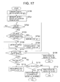
- FIG. 17 shows a variation of the defect information management method of the second preferred embodiment.
- the defect information management method of the present embodiment is a process of finding a target defect item in the defect list.
- the defect list which is shown in FIG. 16, is used.
- the steps of the finding process of FIG. 17 are essentially the same as corresponding steps of the finding process of FIG. 15, and a description thereof will be omitted for the sake of avoiding a duplicate description.
- the defect information management method of the present embodiment is effective in providing an easy, efficient finding process that finds out the target defect item in the defect list, by using the defect list shown in FIG. 16 .
- FIG. 18 shows a process of addition of new defect information to a defect list according to a third preferred embodiment of the invention.
- the defect list of the present embodiment which is indicated by (A) in FIG. 18, is stored in the magnetic disk 2 of the magnetic disk system of FIG. 1 and transferred to the data buffer 14 for the access.
- the defect list was produced with a sequence of sets of primary defect items.
- the sets of the primary defect items in the defect list are arrayed in sequential order of the cylinder numbers of the magnetic disk 2 corresponding to the respective sets.
- a unique cylinder number is assigned for each of the sets of the primary defect items, such as cylinder 0 , . . . , cylinder“n”.
- Each primary defect item indicates a location of one of the primary defects on the magnetic disk 2 .
- the addition process of the present embodiment is executed by the MCU 10 .
- the determining step/unit, the calculating step/unit, the transferring step/unit and the adding step/unit in the defect information management method and apparatus of the claims are achieved by program control instructions stored in the MCU 10 .
- the cylinder 0 secondary defect item is inserted at the original location of the next set (cylinder 1 ) of primary defect items in the defect list.
- the next set of primary defect items (the cylinder 1 primary defect items) are transferred to the end of the defect list, so as to create a vacant area in the defect list at the original location.
- the secondary defect item is added to the original location of the moved primary defect items. The vacant area from the end of the added defect item remains unchanged.
- FIG. 19 shows a defect information management method of the third preferred embodiment of the invention.
- the defect information management method of the present embodiment is a process of addition of new defect information to the defect list. In this addition process, the defect list of FIG. 18 described above is used.
- the second defect item, and the next-location first defect items at a location following the location of the first defect items in the same cylinder as that of the second defect item are determined by using the layout table (S 80 ).
- step S 80 After the step S 80 is performed, a size of the second defect item to be added, and a size of the next-location first defect items are calculated (S 81 ). This step is performed to check a size of the vacant area produced after the addition of the second defect item.
- step S 81 it is determined whether the size of the next-location first defect items is smaller than the size of the second defect item (S 82 ). When the result at the step S 82 is affirmative, it is necessary to enlarge the size of the next-location first defect items.
- the next-location first defect items are transferred to the end of the defect list (S 83 ).
- the offset address of the next-location first defect items in the layout table is changed so as to be in conformity with the transfer (S 84 ).
- step S 84 the above steps S 80 through S 83 are repeated until the result at the step S 82 indicates a negative answer.
- the step S 84 When the result at the step S 84 is negative, the size of the next-location first defect items is enough to add the second defect item. Then, the second defect item is added to the original location of the moved first defect items (S 85 ). The vacant area from the end of the added defect item remains unchanged. After the step S 85 is performed, the addition process ends.
- the defect information management method and apparatus of the present embodiment does not require the transfer of all the subsequent-cylinder defect information when adding new defect information.
- the defect information management method and apparatus of the present embodiment is effective in providing quick and efficient management of defect information of the storage medium in a magnetic disk system.
- FIG. 20 shows a process of optimization of the defect list performed after a vacant area was created in the addition process.
- vacant areas between two adjacent ones of the sets of first defect items may remain after the end of the addition process, as shown in FIG. 18 .
- the defect list indicated by (A) in FIG. 20 is in such a condition.
- the former of the two adjacent sets of first defect items is indicated by “p”, and the latter is indicated by “q”.
- the vacant areas are produced after the end of the addition process of FIG. 19 .
- the optimization process of FIG. 20 is to transfer the first defect item set “q” to the end of the first defect item set “p”. so as to merge one of the vacant areas into another in the defect list, as indicated by (B) in FIG. 20 .
- the optimization process of the present embodiment is executed by the MCU 10 , and the second transferring step and unit in the defect information management method and apparatus of the claims are achieved by program control instructions stored in the MCU 10 .
- the optimization process of the present embodiment is effective in increasing the storage space available for adding new defect information.
- FIG. 21 shows a variation of the defect information management method of the third preferred embodiment.
- the defect information management method of the present embodiment is a process of optimization of the defect list in the above-mentioned condition after the end of the addition process. In this optimization process, the defect list of FIG. 20 described above is used.
- the defect items “p” at the first location in the defect list are obtained or read out (S 90 ). It is determined whether the first location defect items “p” in the defect list can be successfully obtained (S 91 ).
- the optimization process immediately ends.
- the result at the step S 91 is affirmative, the first-location defect items “p” can be obtained.
- the defect items “q” at the next location in the defect list are obtained or read out (S 92 ). It is determined whether the next-location defect items “q” in the defect list can be successfully obtained (S 93 ).
- the optimization process immediately ends.
- the result at the step S 93 is affirmative, it is determined whether a vacant area between the first-location defect items “p” and the next-location defect items “q” in the defect list exists (S 94 ).
- the defect items “q” (the latter of the two adjacent sets of first defect items in the defect list) are transferred to the end of the defect items “p” (the former set) (S 95 ).
- the address of the defect items “q” in the defect list is changed to the new one after the movement (S 96 ).
- the value “q” is replaced with the value “p” for the processing of a subsequent location in the defect list (S 97 ).
- step S 94 When the result at the step S 94 is negative, the above steps S 95 and S 96 are not performed and only the step S 97 is performed. After the step S 97 is performed, the above steps S 92 through S 96 are repeated until the processing of the end location in the defect list is complete.
- the defect information management method and apparatus of the present embodiment are effective in increasing the storage space available for adding new defect information. Further, the defect information management method and apparatus of the present embodiment do not require the transfer of all the subsequent-location defect information when adding new defect information.
- the defect information management method and apparatus of the present embodiment are effective in providing quick and efficient management of defect information of the storage medium in a magnetic disk system.
- FIG. 22 shows a process of optimization of the defect list performed after a vacant area was created in the addition process.
- the optimization process of the present embodiment is to merge the second vacant area into the first vacant area by transferring the cylinder 2 defect items to a subsequent location in the defect list as indicated by (B) in FIG. 22 .
- the storage space (or the data buffer 14 in the magnetic disk system of FIG. 1) available can be increased with the merged vacant area.
- the defect information management method of the present embodiment makes it possible to transfer the cylinder 3 defect items from the end of the defect list to the end of the cylinders defect items, as indicated by (C) in FIG. 22 .
- the defect information management method of the present embodiment is effective in increasing the storage space available for adding new defect information.
Abstract
Description
Claims (8)
Applications Claiming Priority (2)
| Application Number | Priority Date | Filing Date | Title |
|---|---|---|---|
| JP11192313A JP2001023314A (en) | 1999-07-06 | 1999-07-06 | Defect information control method and information storage device |
| JP11-192313 | 1999-07-06 |
Publications (1)
| Publication Number | Publication Date |
|---|---|
| US6701465B1 true US6701465B1 (en) | 2004-03-02 |
Family
ID=16289213
Family Applications (1)
| Application Number | Title | Priority Date | Filing Date |
|---|---|---|---|
| US09/539,947 Expired - Fee Related US6701465B1 (en) | 1999-07-06 | 2000-03-31 | Method and apparatus for management of defect information in a disk system |
Country Status (3)
| Country | Link |
|---|---|
| US (1) | US6701465B1 (en) |
| JP (1) | JP2001023314A (en) |
| DE (1) | DE10020190B4 (en) |
Cited By (7)
| Publication number | Priority date | Publication date | Assignee | Title |
|---|---|---|---|---|
| US20020071193A1 (en) * | 2000-12-11 | 2002-06-13 | Hitoshi Ogawa | Disk apparatus |
| US20040153745A1 (en) * | 2002-11-20 | 2004-08-05 | Hitachi Global Storage Technologies Netherlands B.V. | Bad-sector search method, data recording device, and program |
| US20040153845A1 (en) * | 2002-11-19 | 2004-08-05 | Samsung Electronics Co., Ltd. | HDD defect list searching method |
| US20110280114A1 (en) * | 2009-01-14 | 2011-11-17 | Mats Oberg | Method and apparatus for determining a location of a defect on a storage medium |
| US20170068474A1 (en) * | 2015-09-08 | 2017-03-09 | Kabushiki Kaisha Toshiba | Method of managing defects in recording medium and storage apparatus |
| US20190391085A1 (en) * | 2017-09-13 | 2019-12-26 | Applied Materials Israel Ltd. | System, method and computer program product for object examination |
| US20200192795A1 (en) * | 2018-12-18 | 2020-06-18 | Seagate Technology Llc | Large range defect allocation system and method |
Families Citing this family (2)
| Publication number | Priority date | Publication date | Assignee | Title |
|---|---|---|---|---|
| JP4568273B2 (en) * | 2003-06-23 | 2010-10-27 | パナソニック株式会社 | Apparatus and method for searching recordable area, apparatus and method for updating recording management information, integrated circuit, write-once information recording medium |
| JP4299809B2 (en) | 2005-06-21 | 2009-07-22 | 日本電気株式会社 | Defect information management method, information recording / reproducing apparatus, and information reproducing apparatus |
Citations (7)
| Publication number | Priority date | Publication date | Assignee | Title |
|---|---|---|---|---|
| US4498146A (en) * | 1982-07-30 | 1985-02-05 | At&T Bell Laboratories | Management of defects in storage media |
| JPH02278572A (en) | 1989-04-20 | 1990-11-14 | Fujitsu Ltd | Alternative block processing system |
| US5146571A (en) * | 1988-03-28 | 1992-09-08 | Emc Corporation | Remapping defects in a storage system through the use of a tree structure |
| US5935258A (en) * | 1997-03-04 | 1999-08-10 | Micron Electronics, Inc. | Apparatus for allowing data transfers with a memory having defective storage locations |
| US6249888B1 (en) * | 1998-10-22 | 2001-06-19 | Matsushita Electric Industrial Co., Ltd. | Information recording medium, and method and apparatus for managing defect thereof |
| US6279089B1 (en) * | 1999-04-12 | 2001-08-21 | Western Digital Technologies, Inc. | Defective data site management through a shared defect management table |
| US6385736B1 (en) * | 1997-12-23 | 2002-05-07 | Lg Electronics, Inc. | Method and apparatus for managing defect areas of recording medium using sector number comparison techniques |
-
1999
- 1999-07-06 JP JP11192313A patent/JP2001023314A/en active Pending
-
2000
- 2000-03-31 US US09/539,947 patent/US6701465B1/en not_active Expired - Fee Related
- 2000-04-25 DE DE10020190A patent/DE10020190B4/en not_active Expired - Fee Related
Patent Citations (7)
| Publication number | Priority date | Publication date | Assignee | Title |
|---|---|---|---|---|
| US4498146A (en) * | 1982-07-30 | 1985-02-05 | At&T Bell Laboratories | Management of defects in storage media |
| US5146571A (en) * | 1988-03-28 | 1992-09-08 | Emc Corporation | Remapping defects in a storage system through the use of a tree structure |
| JPH02278572A (en) | 1989-04-20 | 1990-11-14 | Fujitsu Ltd | Alternative block processing system |
| US5935258A (en) * | 1997-03-04 | 1999-08-10 | Micron Electronics, Inc. | Apparatus for allowing data transfers with a memory having defective storage locations |
| US6385736B1 (en) * | 1997-12-23 | 2002-05-07 | Lg Electronics, Inc. | Method and apparatus for managing defect areas of recording medium using sector number comparison techniques |
| US6249888B1 (en) * | 1998-10-22 | 2001-06-19 | Matsushita Electric Industrial Co., Ltd. | Information recording medium, and method and apparatus for managing defect thereof |
| US6279089B1 (en) * | 1999-04-12 | 2001-08-21 | Western Digital Technologies, Inc. | Defective data site management through a shared defect management table |
Cited By (17)
| Publication number | Priority date | Publication date | Assignee | Title |
|---|---|---|---|---|
| US20020071193A1 (en) * | 2000-12-11 | 2002-06-13 | Hitoshi Ogawa | Disk apparatus |
| US6954876B2 (en) * | 2000-12-11 | 2005-10-11 | Hitachi Global Storage Technologies Japan, Ltd. | Disk apparatus |
| US20040153845A1 (en) * | 2002-11-19 | 2004-08-05 | Samsung Electronics Co., Ltd. | HDD defect list searching method |
| US7155640B2 (en) * | 2002-11-19 | 2006-12-26 | Samsung Electronics Co., Ltd. | HDD defect list searching method |
| US20040153745A1 (en) * | 2002-11-20 | 2004-08-05 | Hitachi Global Storage Technologies Netherlands B.V. | Bad-sector search method, data recording device, and program |
| US7197593B2 (en) * | 2002-11-20 | 2007-03-27 | Hitachi Global Storage Technologies Netherlands B.V. | Bad-sector search method, data recording device, and program |
| US8599666B2 (en) | 2009-01-14 | 2013-12-03 | Marvell World Trade Ltd. | Method and apparatus for determining a location of a feature on a storage medium |
| US8305703B2 (en) * | 2009-01-14 | 2012-11-06 | Marvell World Trade Ltd. | Method and apparatus for determining a location of a defect on a storage medium |
| US20110280114A1 (en) * | 2009-01-14 | 2011-11-17 | Mats Oberg | Method and apparatus for determining a location of a defect on a storage medium |
| US8902722B2 (en) | 2009-01-14 | 2014-12-02 | Marvell World Trade Ltd. | Method and apparatus for determining a location of a feature on a storage medium |
| US20170068474A1 (en) * | 2015-09-08 | 2017-03-09 | Kabushiki Kaisha Toshiba | Method of managing defects in recording medium and storage apparatus |
| CN106504779A (en) * | 2015-09-08 | 2017-03-15 | 株式会社东芝 | The defect management method is managed by defect in recording medium and disk device |
| US20190391085A1 (en) * | 2017-09-13 | 2019-12-26 | Applied Materials Israel Ltd. | System, method and computer program product for object examination |
| US10871451B2 (en) * | 2017-09-13 | 2020-12-22 | Applied Materials Israel Ltd. | System, method and computer program product for object examination |
| US11592400B2 (en) | 2017-09-13 | 2023-02-28 | Applied Materials Israel Ltd. | System, method and computer program product for object examination |
| US20200192795A1 (en) * | 2018-12-18 | 2020-06-18 | Seagate Technology Llc | Large range defect allocation system and method |
| US11138105B2 (en) * | 2018-12-18 | 2021-10-05 | Seagate Technology Llc | Large range defect allocation system and method |
Also Published As
| Publication number | Publication date |
|---|---|
| DE10020190A1 (en) | 2001-01-18 |
| JP2001023314A (en) | 2001-01-26 |
| DE10020190B4 (en) | 2005-05-04 |
Similar Documents
| Publication | Publication Date | Title |
|---|---|---|
| US6779081B2 (en) | Apparatus and method for defragmentation in disk storage system | |
| US6263459B1 (en) | On the fly write reallocation | |
| KR100228795B1 (en) | Method for improving the function of read/write of track | |
| KR970701908A (en) | Defect management for automatic track processing without ID field | |
| JPH02263362A (en) | Method for accessing data on recording medium and data recorder using this method | |
| JP4012791B2 (en) | Sector rearrangement method of information recording medium and information storage device | |
| US6728899B1 (en) | On the fly defect slipping | |
| US6701465B1 (en) | Method and apparatus for management of defect information in a disk system | |
| US5084789A (en) | "Parallel transfer type disk system" | |
| CN110289018B (en) | Magnetic disk device and recording method thereof | |
| JPH052830A (en) | Recording and reproducing device and recording and reproducing method in recording and reproducing device | |
| US6301644B1 (en) | Method for managing defect sectors of information storage medium, and apparatus for use with the method | |
| US20040153845A1 (en) | HDD defect list searching method | |
| US20040075933A1 (en) | Method and apparatus for servo defect management | |
| CN112420080B (en) | Magnetic disk device | |
| US6862150B1 (en) | Information storage device and defect information management method | |
| US6941488B2 (en) | Retrieval of a single complete copy from multiple stored copies of information | |
| US4814904A (en) | Method of controlling erasing following format writing in a magnetic disc apparatus | |
| JPH06251506A (en) | Magnetic disk device and alternate track/sector processing method therefor | |
| US4805048A (en) | Method for controlling to keep off defects on magnetic disks | |
| JPH1092116A (en) | Data recording/reproducing apparatus and spare track arrangement method in the apparatus | |
| US20040095671A1 (en) | Data storage device, recording medium, servo writing method, and data reading/writing method | |
| US20220365715A1 (en) | Data storage device using predefined data segments for logical address mapping | |
| JP2595316B2 (en) | Alternate assignment processing method | |
| KR100498420B1 (en) | How to test the performance of your hard disk drive |
Legal Events
| Date | Code | Title | Description |
|---|---|---|---|
| AS | Assignment |
Owner name: FUJITSU LIMITED, JAPAN Free format text: ASSIGNMENT OF ASSIGNORS INTEREST;ASSIGNOR:TASHIRO, MASAMI;REEL/FRAME:010718/0318 Effective date: 20000321 |
|
| FEPP | Fee payment procedure |
Free format text: PAYOR NUMBER ASSIGNED (ORIGINAL EVENT CODE: ASPN); ENTITY STATUS OF PATENT OWNER: LARGE ENTITY |
|
| FPAY | Fee payment |
Year of fee payment: 4 |
|
| AS | Assignment |
Owner name: TOSHIBA STORAGE DEVICE CORPORATION, JAPAN Free format text: ASSIGNMENT OF ASSIGNORS INTEREST;ASSIGNOR:FUJITSU LIMITED;REEL/FRAME:023419/0031 Effective date: 20091014 Owner name: TOSHIBA STORAGE DEVICE CORPORATION, JAPAN Free format text: ASSIGNMENT OF ASSIGNORS INTEREST;ASSIGNOR:FUJITSU LIMITED;REEL/FRAME:023861/0881 Effective date: 20091014 Owner name: TOSHIBA STORAGE DEVICE CORPORATION,JAPAN Free format text: ASSIGNMENT OF ASSIGNORS INTEREST;ASSIGNOR:FUJITSU LIMITED;REEL/FRAME:023861/0881 Effective date: 20091014 |
|
| XAS | Not any more in us assignment database |
Free format text: ASSIGNMENT OF ASSIGNORS INTEREST;ASSIGNOR:FUJITSU LIMITED;REEL/FRAME:023419/0031 |
|
| REMI | Maintenance fee reminder mailed | ||
| LAPS | Lapse for failure to pay maintenance fees | ||
| STCH | Information on status: patent discontinuation |
Free format text: PATENT EXPIRED DUE TO NONPAYMENT OF MAINTENANCE FEES UNDER 37 CFR 1.362 |
|
| FP | Lapsed due to failure to pay maintenance fee |
Effective date: 20120302 |