US6697525B1 - System method and apparatus for performing a transform on a digital image - Google Patents
System method and apparatus for performing a transform on a digital image Download PDFInfo
- Publication number
- US6697525B1 US6697525B1 US09/166,109 US16610998A US6697525B1 US 6697525 B1 US6697525 B1 US 6697525B1 US 16610998 A US16610998 A US 16610998A US 6697525 B1 US6697525 B1 US 6697525B1
- Authority
- US
- United States
- Prior art keywords
- uncompressed
- block
- blocks
- compressed
- engine
- Prior art date
- Legal status (The legal status is an assumption and is not a legal conclusion. Google has not performed a legal analysis and makes no representation as to the accuracy of the status listed.)
- Expired - Lifetime
Links
- 238000000034 method Methods 0.000 title claims description 45
- 238000004364 calculation method Methods 0.000 claims description 10
- 238000007906 compression Methods 0.000 abstract description 56
- 230000006835 compression Effects 0.000 abstract description 46
- 238000013144 data compression Methods 0.000 abstract description 11
- 230000008569 process Effects 0.000 description 23
- 238000012545 processing Methods 0.000 description 18
- 230000001131 transforming effect Effects 0.000 description 17
- 238000004891 communication Methods 0.000 description 16
- 238000003491 array Methods 0.000 description 10
- 230000005540 biological transmission Effects 0.000 description 10
- 239000011159 matrix material Substances 0.000 description 10
- 238000013139 quantization Methods 0.000 description 10
- 230000008901 benefit Effects 0.000 description 5
- 238000012360 testing method Methods 0.000 description 4
- 238000012546 transfer Methods 0.000 description 4
- 238000006243 chemical reaction Methods 0.000 description 3
- 238000010586 diagram Methods 0.000 description 3
- 230000003287 optical effect Effects 0.000 description 2
- AZFKQCNGMSSWDS-UHFFFAOYSA-N MCPA-thioethyl Chemical compound CCSC(=O)COC1=CC=C(Cl)C=C1C AZFKQCNGMSSWDS-UHFFFAOYSA-N 0.000 description 1
- 230000008859 change Effects 0.000 description 1
- 238000007796 conventional method Methods 0.000 description 1
- 238000013461 design Methods 0.000 description 1
- 238000011161 development Methods 0.000 description 1
- 238000003745 diagnosis Methods 0.000 description 1
- 238000002059 diagnostic imaging Methods 0.000 description 1
- 238000005516 engineering process Methods 0.000 description 1
- 230000006870 function Effects 0.000 description 1
- 230000008520 organization Effects 0.000 description 1
- 230000002093 peripheral effect Effects 0.000 description 1
- 230000003252 repetitive effect Effects 0.000 description 1
Images


Classifications
-
- H—ELECTRICITY
- H04—ELECTRIC COMMUNICATION TECHNIQUE
- H04N—PICTORIAL COMMUNICATION, e.g. TELEVISION
- H04N19/00—Methods or arrangements for coding, decoding, compressing or decompressing digital video signals
- H04N19/10—Methods or arrangements for coding, decoding, compressing or decompressing digital video signals using adaptive coding
- H04N19/102—Methods or arrangements for coding, decoding, compressing or decompressing digital video signals using adaptive coding characterised by the element, parameter or selection affected or controlled by the adaptive coding
- H04N19/12—Selection from among a plurality of transforms or standards, e.g. selection between discrete cosine transform [DCT] and sub-band transform or selection between H.263 and H.264
- H04N19/122—Selection of transform size, e.g. 8x8 or 2x4x8 DCT; Selection of sub-band transforms of varying structure or type
-
- H—ELECTRICITY
- H04—ELECTRIC COMMUNICATION TECHNIQUE
- H04N—PICTORIAL COMMUNICATION, e.g. TELEVISION
- H04N19/00—Methods or arrangements for coding, decoding, compressing or decompressing digital video signals
- H04N19/10—Methods or arrangements for coding, decoding, compressing or decompressing digital video signals using adaptive coding
- H04N19/134—Methods or arrangements for coding, decoding, compressing or decompressing digital video signals using adaptive coding characterised by the element, parameter or criterion affecting or controlling the adaptive coding
- H04N19/136—Incoming video signal characteristics or properties
- H04N19/14—Coding unit complexity, e.g. amount of activity or edge presence estimation
-
- H—ELECTRICITY
- H04—ELECTRIC COMMUNICATION TECHNIQUE
- H04N—PICTORIAL COMMUNICATION, e.g. TELEVISION
- H04N19/00—Methods or arrangements for coding, decoding, compressing or decompressing digital video signals
- H04N19/10—Methods or arrangements for coding, decoding, compressing or decompressing digital video signals using adaptive coding
- H04N19/169—Methods or arrangements for coding, decoding, compressing or decompressing digital video signals using adaptive coding characterised by the coding unit, i.e. the structural portion or semantic portion of the video signal being the object or the subject of the adaptive coding
- H04N19/17—Methods or arrangements for coding, decoding, compressing or decompressing digital video signals using adaptive coding characterised by the coding unit, i.e. the structural portion or semantic portion of the video signal being the object or the subject of the adaptive coding the unit being an image region, e.g. an object
- H04N19/176—Methods or arrangements for coding, decoding, compressing or decompressing digital video signals using adaptive coding characterised by the coding unit, i.e. the structural portion or semantic portion of the video signal being the object or the subject of the adaptive coding the unit being an image region, e.g. an object the region being a block, e.g. a macroblock
Definitions
- the invention is related generally to a system for building data compression devices and more particularly, to a system for building a data compression device for coding of images.
- bandwidth the amount of data capable of being transmitted through a given media over time.
- JPEG Joint Photographic Experts Group
- CITT International Circuit and Telephone Consultative Committee
- ISO 10918:1 International Standards Organization and International Electrotechnical Commission
- the JPEG standard actually comprises two classes of compression processes, namely, lossy and lossless compression techniques.
- lossy compression substantial compression is achieved while some loss of the image data occurs when the image is subsequently decompressed. However, such losses in image quality may be so minimal that they are generally not considered discernable when viewed by the naked eye.
- DCT discrete cosine transform
- An encoder 20 (FIG. 1) using lossy compression generally includes a DCT engine 21 , a quantizer 22 and an entropy coder 26 . These functions are defined in the JPEG standard.
- lossless compression is achieved using an alternative technique to DCT in which no loss in image quality occurs when the image is decompressed.
- lossless compression does not achieve compression ratios as large as lossy compression.
- digital images when compressed under a lossless compression will have a greater file size and will take more time to transfer through a communications line than the same image when compressed over the lossy standard.
- image accuracy is desired, such as, in medical imaging where any change in the representation of an image containing human tissue may affect the diagnosis of an illness by a medical professional, most image applications can utilize the lossy compression standard for digital transmission.
- the JPEG standard for compressing digital images is more than capable of simultaneously compressing the data in conjunction with the transmission of the images. This is due to the fact that the narrow bandwidth of conventional analog phone lines for digital data transmission is inherently slower than other digital communications methods and provides more than adequate time for the simultaneous JPEG compression processes to occur in real time.
- other hardware communications systems that have improved digital throughput or have been designed for digital transmission, such as computer buses and networks as well as digital television systems, the availability and need for even greater throughput and speed is in demand.
- the Moving Pictures Experts Group (MPEG) standard for compressing and transmitting moving picture images which is based upon the JPEG standard is also limited by this time constraint.
- MPEG Moving Pictures Experts Group
- faster methods are needed for compressing and storing JPEG images prior to when image data is transferred, for example, to personal computers (PCs) from peripheral devices or for use with the storing of images in digital cameras and the like.
- PCs personal computers
- the compression time needed to convert digital images into the JPEG standard using conventional JPEG compression methods can slow down the overall transmission rate of such high speed communications systems.
- the time saved in transferring such compressed files has been reduced in part by the time needed by conventional compression techniques to encode a digital image into the JPEG file format.
- Such time constraints limit the effectiveness of the JPEG file format in applications that require the compression and transmission to occur quickly, simultaneously and/or in real time.
- DCT discrete cosine transform
- An advantage of the present invention is the ability to provide a good quality image from a lossy compression process having improved compression rates.
- Another advantage of the present invention is improved timing by eliminating DCT cycles not needed, but performed during conventional lossy compression.
- a further advantage of the present invention is that it can be manufactured on an economical basis and has portability between various communication platforms.
- a further advantage of the present invention is the capability to discriminate between types of uncompressed digital image data and to provide a lossy coding stage for a first set of image data and to perform conventional DCT on the second set of image data, thereby eliminating the need for use of the DCT on the first set of data.
- the present invention is embodied in a data compression system for transforming a data set from an uncompressed standard to a compressed standard in which the data set when stored on a storage media under the compressed standard requires less space than the data set when stored under the uncompressed standard.
- the system comprises a discrete cosine transform engine including means for apportioning the data set when uncompressed into a plurality of uncompressed blocks; an inference engine adapted to divide the blocks into predicted blocks and unpredicted blocks by manipulating each of the blocks according to predetermined criteria and comparing each of the manipulated blocks to a predetermined set of compressed block standards; means for assigning a selected one of a plurality of compressed blocks to each of the predicted blocks based upon the comparisons made by the inference engine; and the discrete cosine transform engine further including means for transforming said unpredicted blocks into compressed blocks; such that the data set may be stored under the compressed standard in which assigning the selected compressed block to the predicted block generally appears as though the predicted block was compressed by the transforming means.
- the present invention includes a method of data compression for transforming a data set from an uncompressed standard to a compressed standard in which the data set when stored on a storage media under the compressed standard requires less space than the data set when stored under the uncompressed standard.
- the method comprises the steps of apportioning the data set when uncompressed into a plurality of uncompressed blocks; dividing the blocks into predicted blocks and unpredicted blocks by manipulating each of the blocks according to predetermined criteria; comparing each of the manipulated blocks to a predetermined set of compressed block standards; assigning a selected one of a plurality of compressed blocks to each of the predicted blocks based upon the comparisons; and transforming by a discrete cosine transform the unpredicted blocks into compressed blocks.
- the present invention includes a data compression apparatus for transforming a data set from an uncompressed standard to a compressed standard in which the data set when stored on a storage media under the compressed standard requires less space than the data set when stored under the uncompressed standard.
- the apparatus comprises a discrete cosine transform engine including means for apportioning the data set when uncompressed into a plurality of uncompressed blocks; an inference engine adapted to divide the blocks into predicted blocks and unpredicted blocks by manipulating each of the blocks according to predetermined criteria and comparing each of the manipulated blocks to a predetermined set of compressed block standards; means for assigning a selected one of a plurality of compressed blocks to each of the predicted blocks based upon the comparisons made by the inference engine; and the discrete cosine transform engine further including means for transforming the unpredicted blocks into compressed blocks; such that the data set may be stored under the compressed standard in which assigning the selected compressed block to the predicted block generally appears as though the predicted block was compressed by the transforming means.
- the present invention is embodied in a data compression system for transforming a digital image from an Y, Cb, Cr image data to a JPEG image data in which the digital image when stored on a storage media under the JPEG image data requires less space than the digital image when stored under the Y, Cb, Cr image data.
- the system comprises a discrete cosine transform engine including means for apportioning the digital image when uncompressed into a plurality of uncompressed 8 ⁇ 8 arrays; an inference engine adapted to divide the 8 ⁇ 8 arrays into predicted 8 ⁇ 8 arrays and unpredicted 8 ⁇ 8 arrays by manipulating each of the 8 ⁇ 8 arrays according to predetermined criteria and comparing each of the manipulated 8 ⁇ 8 arrays to a predetermined set of compressed 8 ⁇ 8 array standards; means for assigning a selected one of a plurality of compressed 8 ⁇ 8 arrays to each of the predicted 8 ⁇ 8 arrays based upon the comparisons made by the inference engine; and the discrete cosine transform engine further including means for transforming the unpredicted 8 ⁇ 8 arrays into compressed 8 ⁇ 8 arrays; such that the digital image may be stored under the JPEG image data in which assigning the selected compressed 8 ⁇ 8 array to the predicted 8 ⁇ 8 array generally appears as though the predicted 8 ⁇ 8 array was compressed by the transforming means.
- the present invention is embodied in a data compression system for transforming a data set between an compressed standard in which the data set when stored on a storage media under the compressed standard require less space than the data set when stored under the uncompressed standard.
- the system includes a discrete cosine transform engine including means for selectively apportioning the data set when uncompressed into a plurality of uncompressed blocks; an inference engine adapted to divide the blocks into predicted blocks and unpredicted blocks by manipulating each of the blocks according to predetermined criteria and comparing each of the manipulated blocks to a predetermined set of compressed block standards; means for assigning a selected one of a plurality of compressed blocks to each of the predicted blocks based upon the comparisons made by the inference engine; the discrete cosine transform engine further including means for transforming the unpredicted blocks into compressed blocks; such that the data set may be stored under the compressed standard in which assigning the selected compressed block to the predicted block generally appears as though the predicted block was compressed by the transforming means; means for operating
- the present invention is embodied in a data compression system for transforming a data set from an uncompressed standard to a compressed standard in which the data set when stored on a storage media under the compressed standard requires less space than the data set when stored under the uncompressed standard.
- the system comprises a discrete cosine transform engine including means for apportioning the data set when uncompressed into a plurality of uncompressed blocks; an inference engine adapted to divide the blocks into predicted blocks and unpredicted blocks by manipulating each of the blocks according to predetermined criteria and comparing each of the manipulated blocks to a predetermined set of compressed block standards; means for assigning a selected one of a plurality of compressed blocks to each of the predicted blocks based upon the comparisons made by the inference engine; and the discrete cosine transform engine further including means for transforming the unpredicted blocks into compressed blocks; the inference engine including means: for dividing the blocks into sub-blocks and means for predicting certain combinations that appear regularly in side a sub-block; such that the data set may be stored under the compressed standard in which assigning the selected compressed block to the predicted block generally appears as though the predicted block was compressed by the transforming means.
- FIG. 1 is a block diagram of a JPEG encoder of the prior art.
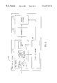
- FIG. 2 is a block diagram of the JPEG encoder of the present invention.
- FIG. 3 is a block diagram of the encoder of the present invention.
- FIG. 4 is a flow chart of a data compiler routine.
- FIG. 5 is a flow chart of a table build routine.
- FIG. 6 is a table of a first set of preliminary DCT calculations.
- FIG. 7 is a table of a second set of preliminary DCT calculations.
- FIG. 8 is a table of the first group of data block cells representative of DCT coefficients.
- FIG. 9 is a table of a second group of data block cells representative of DCT coefficients.
- FIG. 10 is a table of a third group of data block cells representative of DCT coefficients.
- FIG. 11 is a table of a fourth group of data block cells representative of DCT coefficients.
- FIG. 12 is a flow chart of a zero prediction routine.
- FIG. 13 is a flow chart of a non-zero prediction routine.
- FIG. 14 is a conventional zig-zag table.
- the present invention relates generally to an encoder 30 having an input interface 32 to receive images in the form of uncompressed digital data. Since the images may be represented in a variety of color formats, such as, RGB and CMYK formats, a color conversion driver 34 converts color images, if needed, into the YCbCr format for color images as used by the JPEG standard.
- a conventional command set 36 of data values which are user selectable and disclosed in the JPEG standard allow for the user to select certain criteria during the compression process which, for example, allows the user to adjust the degree of compression desired in relation to the quality of the image desired.
- a compression engine 38 connected to a memory 40 , receives the YCbCr format image data and the command set data values and compresses the image data according to criteria determined by the command set data values.
- the memory 40 preferably includes the program software and data used by the compression engine 38 to perform the compression process.
- the compression engine 38 connects to an output interface 39 which transmits the image in the compressed JPEG format to other devices.
- the encoder 30 of the present invention can be implemented in either a software or hardware configuration. It will be appreciated that the input and output interface may cooperate with either software or hardware implemented devices independently from the hardware and/or software implementation of the encoder 30 .
- the present invention further relates to a compression engine 38 (FIG. 3) which includes a DCT engine 42 which operates to first divide the image data into 8 ⁇ 8 pixel blocks 44 and then initializes the data for DCT 45 .
- a compression engine 38 (FIG. 3) which includes a DCT engine 42 which operates to first divide the image data into 8 ⁇ 8 pixel blocks 44 and then initializes the data for DCT 45 .
- each 8 ⁇ 8 grouping of pixels contains three 8 ⁇ 8 blocks of pixels representing the each of the color channels YCbCr.
- These 8 ⁇ 8 data blocks are divided up from the image in a conventional manner in accordance with the JPEG standard.
- the conventional compression process using the DCT engine is interrupted.
- a prediction engine 46 receives each of the 8 ⁇ 8 data blocks and operates to divide up the blocks, or groups of three blocks in the case of color images, into predicted blocks and non-predicted blocks.
- the non-predicted blocks are returned to the DCT engine in which the non-predicted blocks are operated upon conventionally using the DCT transform 48 and a quantizer 50 according to the conventional JPEG standard.
- predicted blocks do not receive subsequent processing under the conventional DCT engine 42 . Rather, the predicted blocks are coded by a prediction coding engine 46 which assigns a predetermined JPEG compressed block for the predicted block.
- a substantial time savings is achieved by eliminating the conventional processing of the block using the DCT engine 42 in which the repetitive process required for performing the discrete cosine transform is eliminated.
- the time required for the prediction engine to operate is significantly less than the DCT process. Thus, even if only a few of the data values for an image are predicted, a significant time savings is achieved.
- the prediction engine may be implemented in two alternatively preferred embodiments. Namely, a zero prediction engine and a non-zero prediction engine that each predicts known combinations of data values which are known to occur regularly.
- the zero prediction engine process subjects each of the 8 ⁇ 8 data blocks to a series of tests to predict whether the blocks conform with known compression results in which all or most of the compressed values equal zero.
- the non-zero prediction engine process the data values are processed and compared to a set of known data values in which the compression results are known. If the data set in the second stage matches a set of the known data values, the compression results of that data set are assigned to the data values.
- the prediction engine 46 may comprise either the zero prediction engine or the non-zero prediction engine.
- the selection of whether to use the zero prediction engine or non-zero prediction engine depends upon the implementation environment in which the encoder is used. Specifically, the non-zero prediction engine relies upon data table to predict the 8 ⁇ 8 data blocks. This requires additional memory which may exceed the memory capacity for conventional Digital Signal Processing (DSP) integrated circuits and thus requires a separate external memory. Where an external memory is undesirable, the zero prediction engine may be preferred.
- DSP Digital Signal Processing
- the enhanced features of the DSP integrated circuit may influence selection. Some conventional devices are enhanced for vector addressing which is ideal for data tables. Other DSP circuits may have enhanced features which reduce the processing time of the zero-prediction engine. Thus, in determining whether to use a zero prediction engine or non-zero prediction engine, the designer must balance the hardware features of the processor and the memory capacity of the device. When space is a premium, a zero-prediction engine may be preferred. Where memory is available, the non-zero prediction engine may be preferred.
- the prediction engine 46 produces three categories of data output: (1) predicted blocks, (2) non-predicted blocks and (3) partially predicted blocks.
- the predicted blocks are those 8 ⁇ 8 data blocks which were successfully predicted and which were pre-assigned with compression results.
- the non-predicted blocks are those blocks in which none of the data values were predicted and the data contained therein is tagged for the DCT process 48 .
- the compression of the non-predicted blocks is accomplished conventionally using the DCT engine 42 and quantizer 50 .
- the partially predicted blocks have a predicted part of the 8 ⁇ 8 data block that is assigned predetermined compression results.
- the non-predicted part of the 8 ⁇ 8 data block is tagged for compression conventionally using the DCT engine 42 and quantizer 50 .
- Processing of the data is completed by an entropy encoder 56 , preferably based upon the Huffman compression algorithm in which the Huffman tables provided by the JPEG preferred embodiment, predicted blocks are not processed by the entropy encoder, as the compression results assigned to these blocks already include the entropy encoder 56 results.
- the Huffman tables may be modified to include results tailored to the partial compression results.
- the Huffman process operates in the manner described in the JPEG standard.
- the zig-zag ordering of the DCT coefficients is shown in FIG. 14 .
- the numbers represent the final ordering of the DCT coefficients before the Huffman process begings.
- the first example is: A 1 . . . A 4 equals no prediction, B 1 . . . B 4 equals prediction. There are several options depending on the size of the look up table created for the Huffman combinations.
- the first option is to perform the regular Huffman until coefficient 24 . From there, continue with the run length of zeros and the 4 prediction codes into a look-up table with 5 layers that will give as a result the complete. Huffman code from coefficient 24 to 64 .
- a second option is to take into account coefficients 1 , 18 , 24 .
- the result of the look-up table is a complete Huffman code from coefficient 13 to 64 .
- a second example is: A 1 is predicted (coefficients 4 , 11 , 13 , 24 ), A 2 . . . A 4 equals not-predicted, B 1 . . . B 4 equals predicted.
- the first option is to perform the regular Huffman until coefficient 19 . From there, continue with a run-length of zeros until coefficient 19 and the 5 prediction codes (A 1 , B 1 . . . B 4 ) into a look-up table.
- a second option is to perform the regular Huffman until coefficient 9 . From there, continue with a run-length of zeros until coefficient 9 and the coefficients 12 , 17 , 18 and the 5 prediction codes (A 1 , B 1 . . . B 4 ) into a look-up table.
- a third example is: A 1 , A 2 equal predicted (coefficients 2 , 4 , 7 , 9 , 11 , 13 , 18 , 24 ), A 3 . . . A 4 are not predicted, B 1 . . . B 4 equal predicted.
- the first option is to perform the regular Huffman coding process until coefficient 9 . From there, continue with a run-length of zeros until coefficient 9 , the coefficient 12 , 17 and the 6 prediction codes (A 1 , A 2 , B 1 . . . B 4 ) into a look-up-table.
- the image data is transmitted to the output interface 39 for use by other devices.
- the compressed data provided by the encoder 30 conforms to the JPEG standard. As such, any hardware or software device designed for use with conventional JPEG files may use the data provided by the present invention.
- the prediction engine operates by examining the data blocks after they have been prepared for processing by the DCT engine.
- the DCT engine divides the image file into 8 ⁇ 8 data blocks where each block contains 64 pixels of image information. In the case of color, there is a separate 8 ⁇ 8 data block for each component of the color image.
- the DCT engine further divides each of the 8 ⁇ 8 data blocks up into four groups of preliminary DCT computation values, each group being made up of 16 values. The selection of the groups and their make-up is determined according to the quantization table selected.
- the selection of the quantization table is related to the image quality and compression ratio of the compressed data file and may vary.
- V 0 j D 07 j
- V 1 j D 16 j
- V 2 j D 25 j
- V 3 j D 34 j
- V 4 j S 07 j
- V 5 j S 16 j
- V 6 j S 25 j
- V 7 j S 34 j
- the 8 ⁇ 8 matrix formed by this process includes a subtraction group and an addition group, each group comprises an 8 ⁇ 4 matrix of 32 values.
- Group IV includes 16 values that have undergone only addition and are identified as G(+)(+).
- Group IV is subjected to a third operation in which a subtraction step of the 16 values is performed as follows:
- these 16 values correspond uniquely as a group to the values of 16 DCT coefficients arranged as shown in FIG. 10 in the 8 ⁇ 8 DCT coefficient matrix.
- the computation of the four groups corresponding to 4 sets of 16 DCT coefficients are all computed conventionally by the DCT engine as a preliminary step in performing the discrete cosine transform on the 8 ⁇ 8 data block. However, before such calculations by the DCT engine begins, the prediction engine performs prediction operations on the four groups.
- a zero prediction operation is outlined by FIG. 12 in which a zero prediction test is performed on each of the four Groups. For each group, the process first determines the Largest Absolute Value (LAV) of the 16 results at step 80 .
- LAV Largest Absolute Value
- This determination can be performed using any conventional sorting or comparing technique in which the absolute value is determined.
- the process may include the following steps:
- the LAV Upon determining the largest absolute value (LAV), the LAV is compared to determine whether the LAV is smaller or equal to 1.5 times the quantization constant A at step 82 .
- A is equal to 4 and the LAV is compared to determine if LAV ⁇ 6. If LAV is less than or equal to 1.5*A, then all the results for Group X are set to zero at step 84 and the next Group is processed at step 86 . Otherwise, the program continues testing of the data.
- the next test at step 88 compares whether LAV is less than or equal to 1.5 times the quantization value B.
- quantization value B 16, so the LAV is compared at step 88 to determine if LAV ⁇ 18. If LAV is less than or equal to 1.5*B, then the twelve values that correspond to B are set to zero at step 90 and the four remaining values of the 24 values are tagged for calculation by the conventional DCT.
- the DCT engine may be initiated by either an interrupt during operation of the prediction engine or upon completion. The decision as to when to implement the DCT engine is a matter of design and depends upon the operation environment of the prediction engine.
- the program then calls then next Group(X)at step 86 .
- the program calls the next Group (X) at step 86 .
- the portions of the data block that are tagged for conventional DCT processing are transmitted to the DCT engine at step 42 for further processing.
- the values tagged for traditional DCT processing 48 may be transmitted at any time after to discovery to provide parallel processing of the DCT engine 42 while the prediction engine 46 finishes its sequence.
- the non-zero prediction engine can be implemented as an alternative to the zero prediction engine.
- the non-zero prediction engine process has a series of look-up tables where each table corresponds to one of the 16 values from the GroupX.
- a table pointer is used in a conventional manner to navigate through the tables.
- the table pointer is initialized at step 96 for reading the first of the 16 values.
- the magnitude of the GroupX(y) value is converted to a correspond to a range of ⁇ 7 to +7.
- a check is made at step 102 to determine whether the value fell within the desired range. If the value is within the desired range, the program continues. Otherwise the program exits at step 104 and no prediction is made.
- the GroupX(y) value is added to the pointer value and used to look-up a record within the table at step 106 .
- a check is made of the record value at step 108 . If the record is “zero”, then there is no prediction of the GroupX.
- the programs calls the next group of values at step 110 . Otherwise, if the value is not equal to zero, the pointer is set to the table record value at step 112 .
- the next value of GroupX is called at step 114 and steps 100 to 114 are repeated until all 16 values have been processed.
- the pointer during the processing of GroupX( 16 ) is assigned a prediction code corresponding to a compressed data for GroupX. If the prediction engine has been successful, then all of the GroupX values are predicted values and no DCT processing of Group X is required.
- the stage two 54 sequence performed by the prediction engine is a conventional look-up table sequence.
- the time saving performance achieved from stage two 54 is acquired from the simplicity of the stage two steps and the creation of the look-up tables which allows for the stage two process to predict non-zero blocks.
- the look-up table may vary according to the application specific criteria such as whether the prediction engine is implemented in hardware and/or software. Further, the tables are tailored to the quantization method used.
- the JPEG standard compresses information by assuming that certain combinations of DCT coefficients consist of more than 90% on average of the results in a given matrix of 8 ⁇ 8 DCT coefficients.
- the general rule for selecting the common combinations is based upon the JPEG Huffman table provided by the JPEG Standard. For the “B” area, some of the common combinations consist of one coefficient being equal to 1 or ⁇ 1 and the other 11 values of the 12 comprising the B area are zero. This occurrence provides a total of 24 combinations that share this common featured.
- Group I prediction codes are A 1 , B 1
- Group II prediction codes are A 2 , B 2 and so on.
- a look-up table may be created based on predicted and unpredicted results that will produce as a result a complete Huffman code from a certain point until the end. This table would further expedite processing of the Huffman coding system for partially predicted blocks of data.
- the encoders incorporating the prediction engine of the present invention may be used in a variety of image processing devices such as optical scanners, digital cameras, digital video disk drives, and the like.
- the implementation can be accomplished in either a hardware form where the encoder is embodied in a conventional Digital Signal Processor (DSP).
- DSP Digital Signal Processor
- the encoder may be implemented in software for use with software applications on general purpose computers.
- the encoder can be used in applications such as: Internet Browsers, Image Viewers and MPEG players.
- the encoder is included with the communication chip-set for an optical scanner.
- the encoder with the time saving prediction allows for the scanner to provide compressed JPEG images to a storage media at a significantly faster rate than conventional Tiff file formats or when using conventional JPEG encoders.
- the encoder is implemented in a digital camera when memory space is a premium.
- the encoder speeds up the transfer and storage of JPEG images to the camera's internal memory. This allows for the digital camera to be used in a manner that emulates conventional auto advancing camera's rapid-shoot cameras.
- the prediction engine of the present invention may be used in conjunction with other compression applications.
- a hard drive controller handles the, storage and transfer of data between a storage media and a computer bus in real time.
- the types of data considered may include but are not limited to binary files, text files, graphics files, and compressed binary files which may include text, binary or graphic matter.
- the identification and compression must occur in real time and should cause a delay in data transfers between the computer bus and hard drive.
- an encoder equipped with a prediction engine may be used to compress the data.
- prediction engine second embodiment using tables may be used to develop encoders for binary text and compressed files as well as image files.
- Such prediction engines would follow similar selection criteria but would require an additional selection of a compression method and a selection of data representative of that format or type of data.
- the criteria for the prediction engine would also need to consider the capacity and speed of the hard drive controller in selecting the type of prediction engine contemplated.
Abstract
Description
| D07j = V0j − V7j | S07j = V0j + V7j |
| D16j = V1j − V6j | S16j = V1j + V6j |
| D25j = V2j − V5j | S25j = V2j + V5j |
| D34j = V3j − V4j | S34j = V3j + V4j |
Claims (13)
Priority Applications (7)
| Application Number | Priority Date | Filing Date | Title |
|---|---|---|---|
| US09/166,109 US6697525B1 (en) | 1998-10-02 | 1998-10-02 | System method and apparatus for performing a transform on a digital image |
| JP2000575070A JP2002527011A (en) | 1998-10-02 | 1999-10-03 | Data compression coding system |
| PCT/IL1999/000522 WO2000021019A2 (en) | 1998-10-02 | 1999-10-03 | Data compression encoding system |
| AT99970187T ATE519333T1 (en) | 1998-10-02 | 1999-10-03 | SYSTEM FOR ENCODING COMPRESSION DATA |
| EP99970187A EP1116154B1 (en) | 1998-10-02 | 1999-10-03 | Data compression encoding system |
| AU59969/99A AU5996999A (en) | 1998-10-02 | 1999-10-03 | Data compression encoding system |
| JP2010273436A JP2011103665A (en) | 1998-10-02 | 2010-12-08 | Data compression encoding system |
Applications Claiming Priority (1)
| Application Number | Priority Date | Filing Date | Title |
|---|---|---|---|
| US09/166,109 US6697525B1 (en) | 1998-10-02 | 1998-10-02 | System method and apparatus for performing a transform on a digital image |
Publications (1)
| Publication Number | Publication Date |
|---|---|
| US6697525B1 true US6697525B1 (en) | 2004-02-24 |
Family
ID=22601866
Family Applications (1)
| Application Number | Title | Priority Date | Filing Date |
|---|---|---|---|
| US09/166,109 Expired - Lifetime US6697525B1 (en) | 1998-10-02 | 1998-10-02 | System method and apparatus for performing a transform on a digital image |
Country Status (6)
| Country | Link |
|---|---|
| US (1) | US6697525B1 (en) |
| EP (1) | EP1116154B1 (en) |
| JP (2) | JP2002527011A (en) |
| AT (1) | ATE519333T1 (en) |
| AU (1) | AU5996999A (en) |
| WO (1) | WO2000021019A2 (en) |
Cited By (5)
| Publication number | Priority date | Publication date | Assignee | Title |
|---|---|---|---|---|
| US20030219161A1 (en) * | 2002-05-23 | 2003-11-27 | Fuji Xerox Co., Ltd. | Image processing device |
| US20040114171A1 (en) * | 2002-09-24 | 2004-06-17 | Hidenori Shindoh | Image forming apparatus and method for consolidated printing |
| US20080052587A1 (en) * | 2006-08-10 | 2008-02-28 | Microsoft Corporation | Unit Test Extender |
| US9536324B1 (en) * | 2015-03-16 | 2017-01-03 | D.R. Systems, Inc. | Dynamic digital image compression based on digital image characteristics |
| US20180131749A1 (en) * | 2016-11-10 | 2018-05-10 | Ingram Micro Inc. | System and Method for Optimizing Data Transfer using Selective Compression |
Families Citing this family (1)
| Publication number | Priority date | Publication date | Assignee | Title |
|---|---|---|---|---|
| KR101517019B1 (en) | 2013-06-07 | 2015-05-11 | 주식회사 큐램 | Adaptive predictive image compression method using block characteristic and system thereof |
Citations (50)
| Publication number | Priority date | Publication date | Assignee | Title |
|---|---|---|---|---|
| US5157488A (en) | 1991-05-17 | 1992-10-20 | International Business Machines Corporation | Adaptive quantization within the jpeg sequential mode |
| US5168375A (en) | 1991-09-18 | 1992-12-01 | Polaroid Corporation | Image reconstruction by use of discrete cosine and related transforms |
| EP0537932A2 (en) | 1991-10-15 | 1993-04-21 | International Business Machines Corporation | Image compression |
| EP0577363A1 (en) | 1992-06-30 | 1994-01-05 | Loral Aerospace Corporation | Compression and reconstruction of radiological images |
| US5319724A (en) | 1990-04-19 | 1994-06-07 | Ricoh Corporation | Apparatus and method for compressing still images |
| US5333212A (en) | 1991-03-04 | 1994-07-26 | Storm Technology | Image compression technique with regionally selective compression ratio |
| WO1995004434A1 (en) | 1993-07-27 | 1995-02-09 | Sri International | Method and apparatus for compression and decompression of digital color images |
| US5410354A (en) | 1993-07-07 | 1995-04-25 | Rca Thomson Licensing Corporation | Method and apparatus for providing compressed non-interlaced scanned video signal |
| US5414780A (en) | 1993-01-27 | 1995-05-09 | Immix | Method and apparatus for image data transformation |
| WO1995035628A1 (en) | 1994-06-17 | 1995-12-28 | Snell & Wilcox Limited | Video compression |
| US5539842A (en) | 1993-06-30 | 1996-07-23 | Ricoh Corporation | Method and apparatus for compressing and decompressing images of documents |
| EP0735772A2 (en) | 1995-03-27 | 1996-10-02 | Hewlett-Packard Company | Method for selecting JPEG quantization tables for low bandwidth applications |
| WO1996032811A2 (en) | 1995-04-12 | 1996-10-17 | Eastman Kodak Company | High capacity compressed document image storage for digital color printers |
| WO1996032691A1 (en) | 1995-04-10 | 1996-10-17 | Rebus Technology, Inc. | System and method for automatic page registration and automatic zone detection during forms processing |
| WO1996033574A1 (en) | 1995-04-18 | 1996-10-24 | Advanced Micro Devices, Inc. | Video decoder apparatus using non-reference frame as an additional prediction source and method therefor |
| US5590064A (en) * | 1994-10-26 | 1996-12-31 | Intel Corporation | Post-filtering for decoded video signals |
| WO1997005748A1 (en) | 1995-07-28 | 1997-02-13 | Polaroid Corporation | Jpeg compression circuit with filtering |
| EP0762775A2 (en) | 1995-08-31 | 1997-03-12 | Hewlett-Packard Company | Device and method for compressing image data |
| US5619594A (en) | 1994-04-15 | 1997-04-08 | Canon Kabushiki Kaisha | Image processing system with on-the-fly JPEG compression |
| WO1997017675A1 (en) | 1995-11-06 | 1997-05-15 | Siemens Medical Systems, Inc. | Method for selecting jpeg quantization factor |
| WO1997017669A1 (en) | 1995-11-08 | 1997-05-15 | Storm Technology, Inc. | Method and format for storing and selectively retrieving image data |
| US5664028A (en) | 1990-04-19 | 1997-09-02 | Ricoh Corporation | Apparatus and method for compressing still images |
| US5671156A (en) | 1995-03-31 | 1997-09-23 | Lucent Technologies Inc. | Transmission method and system for JPEG images |
| WO1997036428A1 (en) | 1996-03-27 | 1997-10-02 | Intergraph Corporation | Real-time high resolution video capture system |
| US5675424A (en) | 1992-05-19 | 1997-10-07 | Goldstar Co., Ltd. | Image decoder for image compression/expansion system |
| US5675666A (en) | 1995-03-02 | 1997-10-07 | Sony Corportion | Image data compression method and apparatus with pre-processing to compensate for the blocky effect |
| USH1684H (en) | 1995-09-29 | 1997-10-07 | Xerox Corporation | Fast preview processing for JPEG compressed images |
| US5682152A (en) | 1996-03-19 | 1997-10-28 | Johnson-Grace Company | Data compression using adaptive bit allocation and hybrid lossless entropy encoding |
| US5701468A (en) | 1994-12-20 | 1997-12-23 | International Business Machines Corporation | System for performing data compression based on a Liu-Zempel algorithm |
| EP0814614A2 (en) | 1996-06-19 | 1997-12-29 | Hewlett-Packard Company | High bit-rate Huffman decoding |
| US5703965A (en) | 1992-06-05 | 1997-12-30 | The Regents Of The University Of California | Image compression/decompression based on mathematical transform, reduction/expansion, and image sharpening |
| US5715176A (en) | 1996-01-23 | 1998-02-03 | International Business Machines Corporation | Method and system for locating a frame position in an MPEG data stream |
| US5717815A (en) | 1995-04-07 | 1998-02-10 | Sony Corporation | Compression data editing apparatus |
| US5719958A (en) | 1993-11-30 | 1998-02-17 | Polaroid Corporation | System and method for image edge detection using discrete cosine transforms |
| US5734755A (en) | 1994-03-11 | 1998-03-31 | The Trustees Of Columbia University In The City Of New York | JPEG/MPEG decoder-compatible optimized thresholding for image and video signal compression |
| US5734892A (en) * | 1992-06-29 | 1998-03-31 | Apple Computer, Inc. | Efficient method and apparatus for access and storage of compressed data |
| EP0833496A2 (en) | 1992-07-20 | 1998-04-01 | Canon Kabushiki Kaisha | Image processing apparatus and image communication apparatus |
| EP0833518A2 (en) | 1996-09-26 | 1998-04-01 | Xerox Corporation | Compression of image data with associated cost data |
| EP0833519A2 (en) | 1996-09-26 | 1998-04-01 | Xerox Corporation | Segmentation and background suppression in JPEG-compressed images using encoding cost data |
| US5745097A (en) | 1995-11-08 | 1998-04-28 | Apple Computer, Inc. | Apparatus and method for automatic image display alignment |
| US5748807A (en) | 1992-10-09 | 1998-05-05 | Panasonic Technologies, Inc. | Method and means for enhancing optical character recognition of printed documents |
| US5751865A (en) | 1996-09-26 | 1998-05-12 | Xerox Corporation | Method and apparatus for image rotation with reduced memory using JPEG compression |
| US5796434A (en) * | 1996-06-07 | 1998-08-18 | Lsi Logic Corporation | System and method for performing motion estimation in the DCT domain with improved efficiency |
| US5815604A (en) * | 1995-05-18 | 1998-09-29 | U.S. Philips Corporation | Interactive image manipulation |
| US5870036A (en) * | 1995-02-24 | 1999-02-09 | International Business Machines Corporation | Adaptive multiple dictionary data compression |
| US5963673A (en) * | 1995-12-20 | 1999-10-05 | Sanyo Electric Co., Ltd. | Method and apparatus for adaptively selecting a coding mode for video encoding |
| US5982432A (en) * | 1997-02-27 | 1999-11-09 | Matsushita Electric Industrial Co., Ltd. | Method and apparatus for converting color component type of picture signals, method and apparatus for converting compression format of picture signals and system for providing picture signals of a required compression format |
| US5982935A (en) * | 1997-04-11 | 1999-11-09 | National Semiconductor Corporation | Method and apparatus for computing MPEG video reconstructed DCT coefficients |
| US5991450A (en) * | 1995-09-06 | 1999-11-23 | Canon Kabushiki Kaisha | Image encoding and decoding apparatus |
| US6130911A (en) * | 1997-11-21 | 2000-10-10 | Sharp Laboratories Of America, Inc. | Method and apparatus for compressing reference frames in an interframe video codec |
Family Cites Families (7)
| Publication number | Priority date | Publication date | Assignee | Title |
|---|---|---|---|---|
| JP2790911B2 (en) * | 1989-12-01 | 1998-08-27 | 株式会社リコー | Orthogonal transform operation unit |
| JPH06105165A (en) * | 1992-09-21 | 1994-04-15 | Nippon Telegr & Teleph Corp <Ntt> | Picture compression device |
| JPH07262175A (en) * | 1994-03-18 | 1995-10-13 | Fujitsu Ltd | Function transformation arithmetic unit |
| JPH0836635A (en) * | 1994-07-26 | 1996-02-06 | Canon Inc | Image processing unit and its method |
| JPH0844708A (en) * | 1994-07-27 | 1996-02-16 | Fujitsu Ltd | Two-dimensional discrete cosine transform arithmetic circuit |
| JP3653799B2 (en) * | 1995-06-09 | 2005-06-02 | 松下電器産業株式会社 | Image encoding device |
| JPH09212484A (en) * | 1996-01-30 | 1997-08-15 | Texas Instr Inc <Ti> | Discrete cosine transformation method |
-
1998
- 1998-10-02 US US09/166,109 patent/US6697525B1/en not_active Expired - Lifetime
-
1999
- 1999-10-03 WO PCT/IL1999/000522 patent/WO2000021019A2/en active Application Filing
- 1999-10-03 AU AU59969/99A patent/AU5996999A/en not_active Abandoned
- 1999-10-03 EP EP99970187A patent/EP1116154B1/en not_active Expired - Lifetime
- 1999-10-03 AT AT99970187T patent/ATE519333T1/en not_active IP Right Cessation
- 1999-10-03 JP JP2000575070A patent/JP2002527011A/en active Pending
-
2010
- 2010-12-08 JP JP2010273436A patent/JP2011103665A/en active Pending
Patent Citations (54)
| Publication number | Priority date | Publication date | Assignee | Title |
|---|---|---|---|---|
| US5664028A (en) | 1990-04-19 | 1997-09-02 | Ricoh Corporation | Apparatus and method for compressing still images |
| US5319724A (en) | 1990-04-19 | 1994-06-07 | Ricoh Corporation | Apparatus and method for compressing still images |
| US5333212A (en) | 1991-03-04 | 1994-07-26 | Storm Technology | Image compression technique with regionally selective compression ratio |
| EP0513520A2 (en) | 1991-05-17 | 1992-11-19 | International Business Machines Corporation | Adaptive quantization within the JPEG sequential mode |
| US5157488A (en) | 1991-05-17 | 1992-10-20 | International Business Machines Corporation | Adaptive quantization within the jpeg sequential mode |
| US5168375A (en) | 1991-09-18 | 1992-12-01 | Polaroid Corporation | Image reconstruction by use of discrete cosine and related transforms |
| EP0537932A2 (en) | 1991-10-15 | 1993-04-21 | International Business Machines Corporation | Image compression |
| US5675424A (en) | 1992-05-19 | 1997-10-07 | Goldstar Co., Ltd. | Image decoder for image compression/expansion system |
| US5703965A (en) | 1992-06-05 | 1997-12-30 | The Regents Of The University Of California | Image compression/decompression based on mathematical transform, reduction/expansion, and image sharpening |
| US5734892A (en) * | 1992-06-29 | 1998-03-31 | Apple Computer, Inc. | Efficient method and apparatus for access and storage of compressed data |
| EP0577363A1 (en) | 1992-06-30 | 1994-01-05 | Loral Aerospace Corporation | Compression and reconstruction of radiological images |
| EP0833496A2 (en) | 1992-07-20 | 1998-04-01 | Canon Kabushiki Kaisha | Image processing apparatus and image communication apparatus |
| US5748807A (en) | 1992-10-09 | 1998-05-05 | Panasonic Technologies, Inc. | Method and means for enhancing optical character recognition of printed documents |
| US5414780A (en) | 1993-01-27 | 1995-05-09 | Immix | Method and apparatus for image data transformation |
| US5539842A (en) | 1993-06-30 | 1996-07-23 | Ricoh Corporation | Method and apparatus for compressing and decompressing images of documents |
| US5410354A (en) | 1993-07-07 | 1995-04-25 | Rca Thomson Licensing Corporation | Method and apparatus for providing compressed non-interlaced scanned video signal |
| US5398066A (en) | 1993-07-27 | 1995-03-14 | Sri International | Method and apparatus for compression and decompression of digital color images |
| WO1995004434A1 (en) | 1993-07-27 | 1995-02-09 | Sri International | Method and apparatus for compression and decompression of digital color images |
| US5719958A (en) | 1993-11-30 | 1998-02-17 | Polaroid Corporation | System and method for image edge detection using discrete cosine transforms |
| US5734755A (en) | 1994-03-11 | 1998-03-31 | The Trustees Of Columbia University In The City Of New York | JPEG/MPEG decoder-compatible optimized thresholding for image and video signal compression |
| US5619594A (en) | 1994-04-15 | 1997-04-08 | Canon Kabushiki Kaisha | Image processing system with on-the-fly JPEG compression |
| WO1995035628A1 (en) | 1994-06-17 | 1995-12-28 | Snell & Wilcox Limited | Video compression |
| US5590064A (en) * | 1994-10-26 | 1996-12-31 | Intel Corporation | Post-filtering for decoded video signals |
| US5701468A (en) | 1994-12-20 | 1997-12-23 | International Business Machines Corporation | System for performing data compression based on a Liu-Zempel algorithm |
| US5870036A (en) * | 1995-02-24 | 1999-02-09 | International Business Machines Corporation | Adaptive multiple dictionary data compression |
| US5675666A (en) | 1995-03-02 | 1997-10-07 | Sony Corportion | Image data compression method and apparatus with pre-processing to compensate for the blocky effect |
| EP0735772A2 (en) | 1995-03-27 | 1996-10-02 | Hewlett-Packard Company | Method for selecting JPEG quantization tables for low bandwidth applications |
| US5671156A (en) | 1995-03-31 | 1997-09-23 | Lucent Technologies Inc. | Transmission method and system for JPEG images |
| US5717815A (en) | 1995-04-07 | 1998-02-10 | Sony Corporation | Compression data editing apparatus |
| WO1996032691A1 (en) | 1995-04-10 | 1996-10-17 | Rebus Technology, Inc. | System and method for automatic page registration and automatic zone detection during forms processing |
| WO1996032811A2 (en) | 1995-04-12 | 1996-10-17 | Eastman Kodak Company | High capacity compressed document image storage for digital color printers |
| WO1996033574A1 (en) | 1995-04-18 | 1996-10-24 | Advanced Micro Devices, Inc. | Video decoder apparatus using non-reference frame as an additional prediction source and method therefor |
| US5724446A (en) | 1995-04-18 | 1998-03-03 | Advanced Micro Devices, Inc. | Video decoder apparatus using non-reference frame as an additional prediction source and method therefor |
| US5815604A (en) * | 1995-05-18 | 1998-09-29 | U.S. Philips Corporation | Interactive image manipulation |
| WO1997005748A1 (en) | 1995-07-28 | 1997-02-13 | Polaroid Corporation | Jpeg compression circuit with filtering |
| US5677689A (en) | 1995-08-31 | 1997-10-14 | Yovanof; Gregory S. | Fixed rate JPEG compliant still image compression |
| EP0762775A2 (en) | 1995-08-31 | 1997-03-12 | Hewlett-Packard Company | Device and method for compressing image data |
| US5991450A (en) * | 1995-09-06 | 1999-11-23 | Canon Kabushiki Kaisha | Image encoding and decoding apparatus |
| USH1684H (en) | 1995-09-29 | 1997-10-07 | Xerox Corporation | Fast preview processing for JPEG compressed images |
| WO1997017675A1 (en) | 1995-11-06 | 1997-05-15 | Siemens Medical Systems, Inc. | Method for selecting jpeg quantization factor |
| WO1997017669A1 (en) | 1995-11-08 | 1997-05-15 | Storm Technology, Inc. | Method and format for storing and selectively retrieving image data |
| US5745097A (en) | 1995-11-08 | 1998-04-28 | Apple Computer, Inc. | Apparatus and method for automatic image display alignment |
| US5963673A (en) * | 1995-12-20 | 1999-10-05 | Sanyo Electric Co., Ltd. | Method and apparatus for adaptively selecting a coding mode for video encoding |
| US5715176A (en) | 1996-01-23 | 1998-02-03 | International Business Machines Corporation | Method and system for locating a frame position in an MPEG data stream |
| US5682152A (en) | 1996-03-19 | 1997-10-28 | Johnson-Grace Company | Data compression using adaptive bit allocation and hybrid lossless entropy encoding |
| WO1997036428A1 (en) | 1996-03-27 | 1997-10-02 | Intergraph Corporation | Real-time high resolution video capture system |
| US5796434A (en) * | 1996-06-07 | 1998-08-18 | Lsi Logic Corporation | System and method for performing motion estimation in the DCT domain with improved efficiency |
| EP0814614A2 (en) | 1996-06-19 | 1997-12-29 | Hewlett-Packard Company | High bit-rate Huffman decoding |
| EP0833518A2 (en) | 1996-09-26 | 1998-04-01 | Xerox Corporation | Compression of image data with associated cost data |
| US5751865A (en) | 1996-09-26 | 1998-05-12 | Xerox Corporation | Method and apparatus for image rotation with reduced memory using JPEG compression |
| EP0833519A2 (en) | 1996-09-26 | 1998-04-01 | Xerox Corporation | Segmentation and background suppression in JPEG-compressed images using encoding cost data |
| US5982432A (en) * | 1997-02-27 | 1999-11-09 | Matsushita Electric Industrial Co., Ltd. | Method and apparatus for converting color component type of picture signals, method and apparatus for converting compression format of picture signals and system for providing picture signals of a required compression format |
| US5982935A (en) * | 1997-04-11 | 1999-11-09 | National Semiconductor Corporation | Method and apparatus for computing MPEG video reconstructed DCT coefficients |
| US6130911A (en) * | 1997-11-21 | 2000-10-10 | Sharp Laboratories Of America, Inc. | Method and apparatus for compressing reference frames in an interframe video codec |
Cited By (15)
| Publication number | Priority date | Publication date | Assignee | Title |
|---|---|---|---|---|
| US7477791B2 (en) | 2002-05-23 | 2009-01-13 | Fuji Xerox Co., Ltd. | Image processing device, method and recording medium for compressing image data |
| US7158683B2 (en) * | 2002-05-23 | 2007-01-02 | Fuji Xerox Co., Ltd. | Image processing device |
| US20070065031A1 (en) * | 2002-05-23 | 2007-03-22 | Fuji Xerox Co., Ltd. | Image processing device, method and recording medium for compressing image data |
| US20070071340A1 (en) * | 2002-05-23 | 2007-03-29 | Fuji Xerox Co., Ltd. | Image processing device, method and recording medium for compressing image data |
| US7298914B2 (en) | 2002-05-23 | 2007-11-20 | Fuji Xerox Co., Ltd. | Image processing device, method and recording medium for compressing image data using repeatability of data patterns |
| US20030219161A1 (en) * | 2002-05-23 | 2003-11-27 | Fuji Xerox Co., Ltd. | Image processing device |
| US20040114171A1 (en) * | 2002-09-24 | 2004-06-17 | Hidenori Shindoh | Image forming apparatus and method for consolidated printing |
| US20080052587A1 (en) * | 2006-08-10 | 2008-02-28 | Microsoft Corporation | Unit Test Extender |
| US7533314B2 (en) * | 2006-08-10 | 2009-05-12 | Microsoft Corporation | Unit test extender |
| US9536324B1 (en) * | 2015-03-16 | 2017-01-03 | D.R. Systems, Inc. | Dynamic digital image compression based on digital image characteristics |
| US9536045B1 (en) * | 2015-03-16 | 2017-01-03 | D.R. Systems, Inc. | Dynamic digital image compression based on digital image characteristics |
| US20170064319A1 (en) * | 2015-03-16 | 2017-03-02 | D.R. Systems, Inc. | Dynamic digital image compression based on digital image characteristics |
| US9800882B2 (en) * | 2015-03-16 | 2017-10-24 | D.R. Systems, Inc. | Dynamic digital image compression based on digital image characteristics |
| US10129553B2 (en) | 2015-03-16 | 2018-11-13 | D.R. Systems, Inc. | Dynamic digital image compression based on digital image characteristics |
| US20180131749A1 (en) * | 2016-11-10 | 2018-05-10 | Ingram Micro Inc. | System and Method for Optimizing Data Transfer using Selective Compression |
Also Published As
| Publication number | Publication date |
|---|---|
| EP1116154A2 (en) | 2001-07-18 |
| ATE519333T1 (en) | 2011-08-15 |
| JP2011103665A (en) | 2011-05-26 |
| WO2000021019A2 (en) | 2000-04-13 |
| AU5996999A (en) | 2000-04-26 |
| JP2002527011A (en) | 2002-08-20 |
| EP1116154B1 (en) | 2011-08-03 |
| EP1116154A4 (en) | 2007-05-02 |
| WO2000021019A3 (en) | 2000-08-03 |
Similar Documents
| Publication | Publication Date | Title |
|---|---|---|
| US6301392B1 (en) | Efficient methodology to select the quantization threshold parameters in a DWT-based image compression scheme in order to score a predefined minimum number of images into a fixed size secondary storage | |
| US6154493A (en) | Compression of color images based on a 2-dimensional discrete wavelet transform yielding a perceptually lossless image | |
| US6124811A (en) | Real time algorithms and architectures for coding images compressed by DWT-based techniques | |
| EP0495490B1 (en) | Video signal encoding apparatus | |
| US6909811B1 (en) | Image processing apparatus and method and storage medium storing steps realizing such method | |
| US6285796B1 (en) | Pseudo-fixed length image compression scheme | |
| US6567562B1 (en) | Encoding apparatus and method | |
| JP4365957B2 (en) | Image processing method and apparatus and storage medium | |
| CN101253761B (en) | Image encoding apparatus and image encoding method | |
| US6211864B1 (en) | Method and apparatus for optimizing storage of compressed images in memory | |
| EP0447203A2 (en) | Data compression and decompression system and method | |
| WO2004064402A1 (en) | Processing of images using a limited number of bits | |
| JP2011103665A (en) | Data compression encoding system | |
| US6396955B1 (en) | Image compression and expansion device | |
| US5805737A (en) | Image signal compressing device | |
| US7046387B1 (en) | Efficient coding of color images including monochrome images | |
| US6266375B1 (en) | Method and apparatus for selecting a quantization table for encoding a digital image | |
| US20020001414A1 (en) | System for building a data compression encoder | |
| JP3469438B2 (en) | Image signal processing method and apparatus, recording medium | |
| US20010014123A1 (en) | Method for processing video | |
| JPH0487460A (en) | Picture processor | |
| US6256421B1 (en) | Method and apparatus for simulating JPEG compression | |
| KR100205286B1 (en) | Image transmitter and method using variable compression according to image specification | |
| US20020176630A1 (en) | Image data processing method | |
| JP2003224868A (en) | Image compression apparatus, image compression method, image compression program, and image expansion program |
Legal Events
| Date | Code | Title | Description |
|---|---|---|---|
| AS | Assignment |
Owner name: MEICOM, LTD., ISRAEL Free format text: ASSIGNMENT OF ASSIGNORS INTEREST;ASSIGNOR:SADEH, RONI M.;REEL/FRAME:010178/0595 Effective date: 19990618 |
|
| AS | Assignment |
Owner name: MEICOM COMPUTERS & COMMUNICATION LTD., ISRAEL Free format text: CORRECTIVE ASSIGNMENT TO CORRECT THE ASSIGNEE'S NAME PREVIOUSLY RECORDED AT REEL 010178 FRAME 0595;ASSIGNOR:SADEH, RONI M.;REEL/FRAME:013385/0712 Effective date: 19990618 |
|
| AS | Assignment |
Owner name: CORAGE LTD., ISRAEL Free format text: ASSIGNMENT OF ASSIGNORS INTEREST;ASSIGNOR:MEICOM COMPUTERS & COMMUNICATION LTD.;REEL/FRAME:013696/0874 Effective date: 20021030 Owner name: PARTHUSCEVA LTD., ISRAEL Free format text: CHANGE OF NAME;ASSIGNOR:CORAGE LTD.;REEL/FRAME:013696/0881 Effective date: 20021107 |
|
| STCF | Information on status: patent grant |
Free format text: PATENTED CASE |
|
| FPAY | Fee payment |
Year of fee payment: 4 |
|
| FEPP | Fee payment procedure |
Free format text: PAYER NUMBER DE-ASSIGNED (ORIGINAL EVENT CODE: RMPN); ENTITY STATUS OF PATENT OWNER: LARGE ENTITY Free format text: PAYOR NUMBER ASSIGNED (ORIGINAL EVENT CODE: ASPN); ENTITY STATUS OF PATENT OWNER: LARGE ENTITY |
|
| FPAY | Fee payment |
Year of fee payment: 8 |
|
| FPAY | Fee payment |
Year of fee payment: 12 |