US6694496B2 - Flexible preamble processing for detecting a code sequence - Google Patents
Flexible preamble processing for detecting a code sequence Download PDFInfo
- Publication number
- US6694496B2 US6694496B2 US09/922,406 US92240601A US6694496B2 US 6694496 B2 US6694496 B2 US 6694496B2 US 92240601 A US92240601 A US 92240601A US 6694496 B2 US6694496 B2 US 6694496B2
- Authority
- US
- United States
- Prior art keywords
- code sequence
- input data
- code
- memory
- results
- Prior art date
- Legal status (The legal status is an assumption and is not a legal conclusion. Google has not performed a legal analysis and makes no representation as to the accuracy of the status listed.)
- Expired - Lifetime, expires
Links
Images


Classifications
-
- H—ELECTRICITY
- H04—ELECTRIC COMMUNICATION TECHNIQUE
- H04B—TRANSMISSION
- H04B1/00—Details of transmission systems, not covered by a single one of groups H04B3/00 - H04B13/00; Details of transmission systems not characterised by the medium used for transmission
- H04B1/69—Spread spectrum techniques
- H04B1/707—Spread spectrum techniques using direct sequence modulation
- H04B1/7073—Synchronisation aspects
- H04B1/7075—Synchronisation aspects with code phase acquisition
- H04B1/7077—Multi-step acquisition, e.g. multi-dwell, coarse-fine or validation
-
- H—ELECTRICITY
- H04—ELECTRIC COMMUNICATION TECHNIQUE
- H04B—TRANSMISSION
- H04B1/00—Details of transmission systems, not covered by a single one of groups H04B3/00 - H04B13/00; Details of transmission systems not characterised by the medium used for transmission
- H04B1/69—Spread spectrum techniques
- H04B1/707—Spread spectrum techniques using direct sequence modulation
- H04B1/7073—Synchronisation aspects
- H04B1/7075—Synchronisation aspects with code phase acquisition
- H04B1/70751—Synchronisation aspects with code phase acquisition using partial detection
-
- H—ELECTRICITY
- H04—ELECTRIC COMMUNICATION TECHNIQUE
- H04B—TRANSMISSION
- H04B2201/00—Indexing scheme relating to details of transmission systems not covered by a single group of H04B3/00 - H04B13/00
- H04B2201/69—Orthogonal indexing scheme relating to spread spectrum techniques in general
- H04B2201/707—Orthogonal indexing scheme relating to spread spectrum techniques in general relating to direct sequence modulation
- H04B2201/70701—Orthogonal indexing scheme relating to spread spectrum techniques in general relating to direct sequence modulation featuring pilot assisted reception
-
- H—ELECTRICITY
- H04—ELECTRIC COMMUNICATION TECHNIQUE
- H04B—TRANSMISSION
- H04B2201/00—Indexing scheme relating to details of transmission systems not covered by a single group of H04B3/00 - H04B13/00
- H04B2201/69—Orthogonal indexing scheme relating to spread spectrum techniques in general
- H04B2201/707—Orthogonal indexing scheme relating to spread spectrum techniques in general relating to direct sequence modulation
- H04B2201/70707—Efficiency-related aspects
-
- H—ELECTRICITY
- H04—ELECTRIC COMMUNICATION TECHNIQUE
- H04J—MULTIPLEX COMMUNICATION
- H04J3/00—Time-division multiplex systems
- H04J3/02—Details
- H04J3/06—Synchronising arrangements
- H04J3/0602—Systems characterised by the synchronising information used
- H04J3/0605—Special codes used as synchronising signal
- H04J3/0611—PN codes
Definitions
- the present claimed invention relates to the field of telecommunication.
- the present claimed invention relates to an apparatus and a method for descrambling data.
- Electronic communication devices such as cell phones, base stations, global positioning systems (GPS) are ubiquitous in everyday business and personal use. IN order to transmit information between two communication devices, they have to know that they exist.
- GPS global positioning systems
- Several different methods identify how a first communication device can determine if a second communication device is trying to transmit to them.
- One such method is to detect a known code sequence transmitted by the second communication device on a specific channel at an unknown offset. By scanning for the known code sequence at different offsets, the first communication device can eventually obtain a match between its internally generated codes and the input data from the second communication device on the specific channel.
- the process of searching input data for known codes is very computationally intensive. Because the known code sequence is a long sequence, the amount of computation that must be performed to span the known code sequence can be extensive. However the computations are somewhat repetitive and may be inefficient. Additionally, part of the known code sequence involves several possible hypotheses. This means that multiple hypotheses will have to be checked to determine if a good correlation exists, and thus more computations are required.
- the computation for the known code sequence can occur ad infinitum. Due to the constant and complicated computations involved, a need also exists to overcome inefficiencies with searching data for a known sequence.
- the search for a new transmission is necessary to establish a link between the two communication devices. Only after a link is established can user data be transmitted between the two communication devices.
- the computations for the known code sequence are extensive and complicated, and thus consume a substantial amount of time. Yet performance metrics dictate that the search be conducted in a short amount of time. Consequently, a need arises for a method and apparatus to overcome the time limitations for searching a channel for the known sequence.
- the present invention provides a method and apparatus that overcomes inefficiencies with the complicated and continuous computations to check a channel for a known sequence. Furthermore, the present invention overcomes the limitation of excessive quantity of data computations used to search for a known sequence on a channel in order to conserve power. Lastly, the present invention overcomes the time limitations for performing the search.
- a first embodiment of the present invention provides an architecture and method for flexible preamble processing.
- the preamble-processing engine detects a code sequence in input, where the code sequence is a sum of a first code sequence and a second code sequence.
- the preamble-processing engine includes a data input line, a code input line, a despreader, and a plurality of memory registers.
- the code input selectively receives the first code sequence or the second code sequence, the first code sequence having a period longer than a period for the second code sequence.
- the despreader is coupled to the data input line and the code input line.
- the despreader producing a despread result between the first code sequence and the input data.
- the plurality of memory registers which are coupled to the despreader, each stores only a portion of the despread results.
- FIG. 1 is a block diagram of an electronic device with a flexible preamble detection system, in accordance with one embodiment of the present invention.
- FIG. 2 is a block diagram of a flexible preamble detection system, in accordance with one embodiment of the present invention.
- FIG. 3A is a block diagram of a flexible preamble detection engine, in accordance with one embodiment of the present invention.
- FIG. 3B is a block diagram of an alternative flexible preamble detection engine, in accordance with one embodiment of the present invention.
- FIG. 4 is a graph of code sequence being sought and the search windows used to find it, in accordance with one embodiment of the present invention.
- FIG. 5A is a flowchart of a process for detecting a code sequence in input signal, in accordance with one embodiment of the present invention.
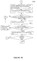
- FIG. 5B is a continuation of the process for detecting a code sequence in input signal, in accordance with one embodiment of the present invention.
- the present invention can be implemented in a wide variety of communication systems, including digital direct sequence spread-spectrum (DSSS) wireless communication systems or techniques that utilize code sequences as well as TDMA and OFDM systems in both wired and wireless applications.
- DSSS digital direct sequence spread-spectrum
- the systems or techniques which utilize transmitter resources include, but are not limited to, fixed wireless, unlicensed Federal Communications Commission (FCC) wireless systems, wireless local area network (W-LAN), cordless telephony, cellular telephony, personal base station, telemetry, modems, and other digital data processing applications.
- FCC Federal Communications Commission
- WLAN wireless local area network
- cordless telephony cellular telephony
- personal base station personal base station
- modems modems
- the present invention can be applied to both transmitters, e.g., a base station, and to receivers, e.g., a terminal, for fixed wireless, W-LAN, cellular telephony, and personal base station applications, or any device that transmits information.
- the present invention is suitable for GPS systems, encryption, and other types of communication using coded data.
- the present invention is applicable to the following exemplary list of digital applications.
- One fixed wireless application to which the present invention may be applied is a metropolitan multipoint distribution system (MMDS). Examples include wireless cable broadcast, or two-way wireless local loop (WLL) systems.
- WLL wireless local loop
- Some examples of a W-LAN, that can communicates digitized audio and data packets, for which the present invention can be applied, include Open Air and the Institute of Electrical and Electronics Engineers (IEEE) specification 802.11b.
- IEEE Institute of Electrical and Electronics Engineers
- specific examples of an unlicensed FCC application to which the present invention may be applied include the Industrial, Scientific, and Medical band (ISM) devices, which can include cordless telephony products.
- ISM Industrial, Scientific, and Medical band
- Personal base stations can utilize either cordless or cellular telephony wireless communication standards.
- the cellular telephony systems in which the present invention can be applied includes, but is not limited to, IS-95, IS2000, ARIB, 3GPP-FDD, 3GPP-TDD, 3GPP2, 1EXTREME, or other user-defined protocols.
- Electronic communication device 100 a provides an exemplary application of the present invention in a wireless direct sequence spread spectrum (DSSS) base transceiver station (BTS) in the present embodiment.
- DSSS wireless direct sequence spread spectrum
- BTS base transceiver station
- Communication device 100 a includes a receiver block 116 that includes front-end processing components (not shown) and rake receiver 119 whose conventional operation is known to those skilled in the art.
- One of the baseband components that are illustrated in FIG. 1 is the preamble detection engine (PDE) 124 .
- Communication device also includes parameter estimator 132 , a microprocessor (uP), or controller, 122 , a memory block 120 , and a transmitter 140 .
- Parameter estimator 132 provides channel estimates on frequency, phase, gain, etc. that are useful by the receiver processor to recover data, as is know by those skilled in the art.
- Microprocessor 122 and a memory block 120 are coupled to transmitter a receiver 116 via bus 117 .
- Host processor 122 and host memory 130 support the management and exchange of data and/or instructions to the various components of communication device 100 a .
- transmitter 140 prepares data signals for subsequent transmission on antenna 101 .
- Hardware resources of communication device 100 a are applied to a single computation process, e.g., a given channel, in one embodiment.
- these hardware resources can be enhanced by running them at a clock rate higher than that required by a process, e.g., higher than the data rate for a communication protocol implemented on communication device 100 a .
- resources of individual computation components, a receiver processor can be time-shared across multiple computation processes, e.g., several multipaths and/or multiple channels. Additional information on the design and implementation of configurations into a configurable communication device is provided in co-pending U.S. patent application Ser. No.
- Communication system 100 a provides an exemplary embodiment of the present invention, which is well suited to alternative embodiments.
- communication system 100 a is mobile handset user equipment (UE) an embedded modem, or an electronic device in another code-dependent application.
- UE mobile handset user equipment
- a three-sector non-diversity antenna array 101 is shown for illustrative purposes only in the present embodiment.
- FIG. 2 a block diagram of a flexible preamble detection system, in accordance with one embodiment of the present invention.
- FIG. 2 provides an exemplary embodiment of PDE 124 of FIG. 1 .
- PDE 124 includes memory 202 for receiving input data, e.g., from antenna 101 of FIG. 1, a MUX 210 to select the I phase of input data for parallel processing on the bank of engines, engines A 220 a through engine M 220 m , through bus 206 .
- a separate bank of engines (not shown) is provided for to process the Q phase of input data. The resultant outputs from the two banks of engines are reconciled in post processing block 228 .
- PDE includes a code 1 engine 220 and a code 2 engine 222 , either of which can be a code generator or a sequence of data stored in memory.
- Code block 1 220 is a long code sequence in the present embodiment, while code block 2 222 is a short code sequence, e.g., a Walsh code generator.
- Code block 1 220 is coupled in parallel to engines, e.g., engine A 220 a through engine M 220 m via line 240 , with delay blocks delay A 230 a through delay M- 1 230 L located between adjacent engines, in PDE 124 . Note that engine A 220 does not have a delay block coupled between engine A 220 and code block 1 220 . This assumes that the first block has zero delay.
- a delay block could be coupled between engine A 220 a and code block 1 220 .
- Delay blocks, 230 a through 230 L are a tap delay line in the present embodiment.
- Code block 2 is also coupled in parallel to each of the multiple engines, e.g. engine A 220 a through engine M 220 m via line 244 . Any number of engines can be implmented in FIG. 2, depending upon the application.
- Post processing block 228 provides functions and components known by those skilled in the art. In an alternative embodiment, post-processing block 228 provides efficient and reduced power frequency offsetting and sorting functions.
- FIG. 3A a block diagram of a flexible preamble detection engine, in accordance with one embodiment of the present invention.
- FIG. 3A provides an exemplary embodiment of flexible engine 220 a of FIG. 2 .
- Flexible engine includes a memory block 314 having multiple individual memories, or registers, labeled PS- 1 300 a through PS-N 300 n for a total quantity of N separate memories.
- Engine 220 a also includes MUX 318 , MUX 322 , and MUX 324 , descramble unit 312 , accumulate register 320 , and accumulate register 316 .
- MUX 318 is linked to line 244 from code block 2 222 and to line 240 from code block 1 220 .
- MUX 318 communicates information from either of these lines to descramble unit 312 .
- MUX 324 is coupled to input line 246 and to feedback line 328 .
- Feedback line 328 is coupled to accumulate register 316 .
- MUX 322 is coupled to feedback line 310 and to line 326 . Output from MUX 322 is provided to accumulate register 320 . Lines 326 and 248 are coupled to accumulate register 320 , the latter to provide final output from engine A 220 a .
- Memory block 314 is implemented as a circular buffer, whose contents scroll down, in the present embodiment.
- Descramble unit 312 is capable of performing complex descrambling operations. These operations include multiplication and/or summing in the present embodiment. However, the present invention is well suited to using an alternative method and apparatus for descrambling. Accumulate registers 320 and 316 perform accumulation operations and store the results in memory.
- Engine A′ 221 a most notably includes two memory blocks 314 and 315 , that provide a ping pong, e.g., dual, buffer architecture that allows simultaneous processing.
- Engine A′ 221 a also includes a selective interconnect 252 , shown as a MUX, coupled to the output of memory blocks 314 and 315 .
- Selective interconnect 252 can couple output line from either memory block 314 or 315 to either feedback line 252 or to descramble unit 313 .
- Output line 252 of MUX 252 is coupled back to accumulate register 320 .
- the other output from MUX 252 is coupled to descramble unit 313 .
- Accumulate register 321 is coupled to receive output from descrambler 313 , and has a feedback to descrambler, as well as an output line 248 .
- accumulate register 320 is coupled to receive output from descramble block 312 , and is coupled to both memory blocks 314 and 315 .
- Input line 244 from Code block 2 222 is coupled to descrambler 313 .
- FIG. 4 a graph of code sequence being sought and the search windows used to find it, in accordance with one embodiment of the present invention.
- FIG. 4 is provided as an illustration of the code sought, and of the search methods used to descramble the code.
- the code that is provided when one communication device wants to establishing a link with another communication device has contributions from two codes.
- the first code is code 1 421 that has a long period, e.g., at least length 403
- the second code is code 2 418 , e.g., a Walsh code, with a much shorter period 418 .
- Code 2 418 is repeated at its period throughout the length of code 1 421 .
- Code 1 421 and code 2 418 both contribute to the resulting code 402 .
- Code 402 is the code that PDE 124 is attempting to detect from input data received on antenna 101 .
- Descrambling, or search, process A 404 a through search process M 404 m conducts a parallel independent descrambling operation with different code offsets from each other, e.g., offset 408 between search process A 404 a and search process B 404 b .
- search processes A 404 a through M 404 m complete their descrambling operations across the search window, e.g., window length 405
- each process A 404 a can continue their respective offset by starting at a distance of 408 away from point 412 , the last search process completed.
- search A′ 410 a An alternative search process is shown as search A′ 410 a through search M 401 m .
- This search process essentially performs a parallel search whose results are added to obtain the overall descrambling results for the entire search window, e.g., to window length 405 .
- the difference between search process A 404 a and search process A′ depends on the relative offsets between the search processes, e.g., offset 408 versus offset 414 , respectively, and the processing control of when the descrambling operation ceases and how the results are combined. More information on these processes is provided in flowcharts embodiments hereinafter.
- FIG. 5A is a flowchart of a process for detecting a code sequence in input signal, in accordance with one embodiment of the present invention.
- FIG. 5A is a flowchart of a process for operating a flexible preamble detection engine, in accordance with one embodiment of the present invention.
- Step 5002 begins with step 5002 .
- an input data sample is received.
- Step 5002 is implemented in one embodiment by receiving a sample, e.g., a multiple bit sample of a received symbol, at PDE from antenna 101 , written to memory 202 , and then communicated via MUX 210 to bus 206 , from which it is separately transmitted to the plurality of engines.
- line 246 communicates the result from bus 206 to descramble block 312 of engine A 220 a via MUX 318 .
- the appropriate logic that enables MUX 318 to pass the input to engine A 220 a is provided by logic in PDE 122 (not shown) or by host controller 122 and host memory 120 .
- Step 5002 flowchart 5000 a proceeds to step 5004 .
- step 5004 of the present embodiment the first code sequence is received.
- Step 5004 is implemented in one embodiment by receiving the first code sequence from Code 1 block 220 of FIG. 2 on line 240 .
- the code is delayed between successive engines, e.g., Engine A 220 a and engine B 220 b and engine M 220 m .
- steps in flowcharts 5000 a and 5000 b exist on a per-engine basis.
- the type of search dictates the amount of the delay.
- Search A 404 a through search M 404 m have an offset of 408 between successive engines running the successive searches. In the present embodiment, this offset is a value of 1 chip and the search is called a parallel search at unique offsets.
- search A 404 a through search M 404 m must each traverse the length of the search window 405 in order to obtain results for their individual searches.
- search method A′ 410 a through M′ 410 m perform a search through the search window length 405 in parallel, dividing up the search window and taking a portion thereof. Consequently, this search methodology takes the search window 405 and divides it by the number of engines, e.g., Engine M 220 m .
- Engine M 220 m the results from all the engines are added to obtain the resultant descrambling operation for the given code offset between the first code and the input data.
- flowchart 5000 a proceeds to step 5006 .
- step 5006 of the present embodiment one sample of the input data is descrambled with one bit of the first code sequence.
- Step 5006 is implemented in one embodiment by descramble block 312 of Engine A 220 a in FIG. 3A or 3 B.
- Descrambling is the operation of performing a multiply operation between two values. Due to the autocorrelation properties, if two code sequences are aligned with zero offset, then the multiplication operation has the effect of recovering a version of the original signal.
- different mathematical operations can be utilized in alternative embodiments to accommodate the despreading function. For example, through manipulation of signals, an add operation can be utilized in one embodiment to accommodate the descrambling operation.
- the present embodiment starts with a zero offset between code 1 and a predetermined boundary of input data, although another embodiment has a non-zero offset.
- flowchart 5000 a proceeds to step 5008 .
- step 5008 of the present embodiment the descrambled result is stored in a portion of memory.
- Step 5008 is implemented in one embodiment by storing the first result in memory block 314 .
- this is the first descrambled result for a given offset, it is automatically written into a buffer in memory.
- this first descrambled result can be stored in memory buffer PS- 1 300 a .
- flowchart 5000 a proceeds to step 5010 .
- step 5010 of the present embodiment another sample of input data is descrambled with another bit of the first code sequence.
- both the input data and the first code sequence advance by one sample and thus maintain the offset, with respect to each other, from which they started.
- Step 5010 is implemented in one embodiment by incrementing the input data received from memory 202 using known memory reading techniques and by incrementing the code from code block 220 using known incrementing techniques.
- flowchart 5000 a proceeds to step 5014 .
- step 5014 of the present embodiment an inquiry determines whether N+1 descrambling operations have been completed. If N+1 descrambling operations have been completed, then flowchart 5000 a proceeds to step 5016 . Otherwise, if N+1 descrambling operations have not been completed, then flowchart 5000 a proceeds to step 5015 .
- N is the length of the second code sequence, thus its period restarts on the Nth+1 value. This is because the descrambling and accumulating operations of the present flowchart are being performed using this same periodicity.
- Step 5002 is implemented in by generating a memory buffer whose quantity of registers is equal to the value of N, as is the case with memory buffer 314 , which has N registers.
- buffer 314 is a circular buffer by virtue of its read and write operations occurring on opposite ends of the buffer. Thus, no logic is effectively required beyond that of the existing read/write logic instructions necessary to operate components in FIG. 3 A.
- Another embodiment utilizes a large memory with write instructions that cycle with the period N.
- Step 5015 arises if N+1 descrambling operations have not been completed per step 5014 .
- the descrambled result is stored in another portion of memory, e.g., another memory register.
- Step 5015 is implemented in one embodiment by operating circular buffer 314 to obtain a new write position.
- the first descrambling result for a given descrambling process was stored in memory register PS- 1 300 a
- the second descrambling result for the given descrambling process will be stored in PS- 2 300 b .
- flowchart 5000 a returns to step 5010 .
- Step 5016 arises if N+1 descrambling operations have been completed per step 5014 .
- the current descrambled result is accumulated with a descrambled result obtained from input data and first code sequence N samples previously.
- Step 5016 is implemented in one embodiment by Engines A 220 a and A′ 221 a as shown in FIGS. 3A and 3B. In short, the descrambled results that are N steps, 2N steps, etc. away from the starting port of the descrambling operation will be accumulated.
- descrambled results between the 1 st data sample and the 1 st bit of first code will be accumulated with the descrambled results from the 17 th data sample and the 17 th bit of the first code, as will be the descrambled results from the 33 rd data sample and the 33 rd bit of the first code.
- the periodicity of these samples is equal to 16, which is the period of the second code sequence, e.g., the Walsh code, for the present embodiment. Because the memory registers of the processing engine A 220 a and engine A′ 221 a also equal N, e.g., 16, then the accumulated data will coincide with the period of the memory registers.
- the present embodiment was set up with this relationship to simplify memory writing in the circular buffer 314 .
- another embodiment utilizes more memory registers, or partitions of memory, than the period for the second code sequence, assuming that control logic tracks the read/write operations for consistency.
- the feedback loops from accumulate register 316 are provided via MUX 322 to be accumulated by block 320 with the results of the present descrambling operation produced by 312 and communicated to block 320 .
- flowchart 5000 a proceeds to step 5018 .
- step 5018 of the present embodiment an inquiry determines whether the search window has been completed. If the search window has been completed, then flowchart 5000 a proceeds to step 5020 . However, if the search window has not been completed, then flowchart 5000 a returns to step 5010 .
- Step 5018 is implemented in one embodiment by control logic that can count the number of elapsed cycles or determines the position of a code sequence and implements a flag for completion of the search window. The end of the search window will occur, for example, when the entire block of search operation A 404 a of FIG. 4A, e.g., operated on Engine A 220 a , passes line 416 which indicates the search window length 405 .
- search window 405 the end of the search window will occur when the entire block of search operation A′ 410 a traverses the quantity of samples represented by length 414 .
- search process M 410 m will have likewise passed line 416 indication the completion of the overall descrambling process for the given offset between the first code sequence and the input data.
- This comparison of search windows on a per engine basis illustrates the tradeoffs such as time to completion between search process A 404 a and search process A′ 410 a .
- the choice of the search window 405 involves a tradeoff between reliability in results versus time to completion. The longer the search window, the more accurate the despreading results, as noise and other errors are offset by valid data.
- Step 5020 arises if the search window has been completed per step 5018 .
- the buffers in memory block 314 have accumulated a search window worth of data, either independently for search processes A 404 a through M 404 m , or cumulatively, for search process A′ 410 through M 410 m .
- one sample of the accumulated descrambled result is read.
- Step 5020 is implemented in one embodiment by reading one register from memory block 314 . For example, if the search window is a multiple of the period of the second code sequence, e.g., length N, then PS- 1 300 a should be in the position shown in FIG. 3 A .
- Step 5020 flowchart 5000 a proceeds to step 5022 , as indicated by connector symbol ‘A’. Flowchart 5000 a continues from FIG. 5A to subsequent FIG. 5 B.
- FIG. 5B is a continuation of the process for detecting a code sequence in an input signal, in accordance with one embodiment of the present invention.
- Flowchart 5000 b of FIG. 5B is a continuation from flowchart 5000 a of FIG. 5A to subsequent FIG. 5 B.
- step 5022 of the present embodiment one bit of the second code sequence undergoes a secondary descrambling operation with one sample of the accumulated descrambled results.
- Step 5022 is implemented in one embodiment by Engine A 220 a .
- Descramble block 312 is the same block used in step 5006 and 5010 .
- MUX 324 now selects feedback line 328 which communications the accumulated descrambled results from the bottom of the memory register 314 to descramble block 312 .
- MUX 318 now selects second code input line 244 to be fed into descramble block 312 .
- Logic for MUX 318 and 324 is described in step 5002 .
- step 5022 is implemented in engine A′ 221 a of FIG.
- Step 5022 flowchart 5000 b proceeds to step 5024 .
- step 5024 of the present embodiment secondary descrambled results are accumulated.
- Step 5024 is implemented in one embodiment by accumulator block 320 (VENU IS This RIGHT?) for engine A 220 a and by accumulator block 321 for engine A′ 221 a .
- flowchart 5000 b proceeds to step 5026 .
- step 5026 of the present embodiment an inquiry determines whether N quantity of secondary descrambling operations have been completed. If N quantity of secondary descrambling operations has been completed, then flowchart 5000 b proceeds to step 5028 . However, if N quantity of secondary descrambling operations has not been completed, then flowchart 5000 b returns to step 5020 , via pointer ‘B’. Step 5026 is implemented in one embodiment by repeating control logic tracking or counting iterations and providing the appropriate control logic to MUXs in engine A 220 and engine A′ 221 a .
- step 5026 A total of N iterations is utilized for step 5026 because of the periodicity of the second code sequence and its relationship to how the descrambled results were sorted and storied in step 5002 through 5016 , which is now being directly used in the descrambling operation.
- Step 5028 arises if N secondary descrambling operations have been completed per step 5026 .
- the accumulated secondary descrambled results are transmitted.
- Step 5028 realizes the goal of the overall PDE, and that is to descramble the input data sample by sample and accumulate the results over the period of the search window.
- the present flowcharts 5000 a and 5000 b accomplish this goal in a segregated manner to achieve efficiencies in mathematical operations. For example, by saving the secondary descrambling operation until the first descrambling operation is complete, a significant quantity of descrambling operations are eliminated by a simple accumulating of intermediate results.
- Step 5028 is implemented in one embodiment by providing control logic to post processing block 228 to accept output results on output line 248 . Following Step 5028 , flowchart 5000 b proceeds to step 5030 .
- step 5030 of the present embodiment an inquiry determines whether all relevant secondary code sequences have been evaluated. If all relevant secondary code sequences have been evaluated, then flowchart 5000 b proceeds to step 5033 . However, if all the relevant code sequences have not been evaluated, then flowchart 5000 b proceeds to step 5032 .
- Step 5030 accommodates for the fact that the entire code sequence is not initially known. Rather, only the long code, e.g., code 1 421 of FIG. 4 is known for certain. That is, multiple possible code sequences exist for the shorter code sequence, e.g., code 2 418 . In one embodiment, sixteen possible hypothesis of a sixteen bit long Walsh code are utilized for the set of hypothesis that must be evaluated to determine if the received signal has any of them.
- the present invention can accommodate any quantity of hypotheses for any length of second code by utilizing flowcharts 5000 a and 5000 b and by having appropriately sized hardware, e.g., memory buffer equal to sequence length N.
- Step 5026 is implemented in one embodiment by control logic, e.g., local control or host controller 122 , that controls generation of second code sequence from code 2 block 222 .
- control logic can reduce the set of possible code sequences for code 2 based on history or instructions.
- Step 5032 arises if all secondary code sequences have been evaluated per step 5030 .
- the offset between the first code and the input data is incremented.
- the offset between the input data and the first code sequence is now incremented. In this manner, steps of 5002 through 5030 are repeated anew for the incremented offset.
- the choice of offset is 1 chip in the present embodiment, although other offsets can be used in another embodiment.
- Step 5032 is implemented in one embodiment by providing control logic to code block 1 220 that will advance the code generator in code space. Memory registers are also cleared to prepare for the next operation.
- flowchart 5000 a and 5000 b are repeated for a second bank of PDE 124 in the present embodiment to accommodate the Q phase of the input data.
- an alternative embodiment can utilize a different configuration to accommodate both phases of the input data.
- flowchart 5000 b proceeds to step 5034 .
- step 5034 of the present embodiment an inquiry determines whether operation is terminated. If operation is terminated, then flowchart 5000 b ends. However, if operation is not terminated, then flowchart 5000 b returns to step 5002 , via pointer ‘C’.
- Step 5034 is effectively implemented in one embodiment by interrupting power to communication device 100 a to terminate operation. Operation of PDE 124 can also occur by a sufficient system interrupt to reset the control and states of the current process in PDE 124 . Alternatively step 5034 is effectively implemented by maintaining power on to allow continued operation of preamble detection system.
- the present invention applies flowcharts 5000 a and 5000 b to a digital wireless communication system
- the present invention can be applied to any electronic device for any type of application.
- the present invention is applicable to mobile units, base stations, etc.
- flowcharts 5000 a and 5000 b of the present embodiment show a specific sequence and quantity of steps
- the present invention is suitable to alternative embodiments. For example, not all the steps provided in the aforementioned flowcharts are required for the present invention. Similarly, other steps may be omitted depending upon the application.
- the present invention is well suited to incorporating additional steps to those presented, as required by an application, or as desired for permutations in the process.
- the sequence of the steps for flowcharts 5000 a and 5000 b can be modified depending upon the application.
- the present flowcharts are shown as a single serial process, they can also be implemented as a continuous or parallel process.
- the data is represented as physical (electronic) quantities within the communication devices components, or the computer system's registers and memories, and is transformed into other data similarly represented as physical quantities within the communication device components, or computer system memories or registers, or other such information storage, transmission or display devices.
- the present invention has been shown to provide a method and apparatus that overcomes the limitations associated with the varied hardware, software, and methodology of transmitting digital signals that are unique and incompatible between each of the various communication protocols. Furthermore, embodiments described for the present invention overcome the lack of forward compatibility associated with incremental improvements in communication protocols. Additionally, the present invention overcomes the potential mismatch between transmitter resources designed for a specific channel format and the changing transmitter resource demand in a given communication device. The limitations of fixed interfaces between transmitter resources and antenna resources and the limitations of a cross bar switch in selectively coupling transmitter resources to antenna resources are also overcome by the method and apparatus of the present invention. The present invention also overcomes the limitations of pushing data through a communications device to the transmitter.
Abstract
Description
Claims (18)
Priority Applications (1)
| Application Number | Priority Date | Filing Date | Title |
|---|---|---|---|
| US09/922,406 US6694496B2 (en) | 2000-08-03 | 2001-08-03 | Flexible preamble processing for detecting a code sequence |
Applications Claiming Priority (2)
| Application Number | Priority Date | Filing Date | Title |
|---|---|---|---|
| US22285500P | 2000-08-03 | 2000-08-03 | |
| US09/922,406 US6694496B2 (en) | 2000-08-03 | 2001-08-03 | Flexible preamble processing for detecting a code sequence |
Publications (2)
| Publication Number | Publication Date |
|---|---|
| US20020016949A1 US20020016949A1 (en) | 2002-02-07 |
| US6694496B2 true US6694496B2 (en) | 2004-02-17 |
Family
ID=22833990
Family Applications (1)
| Application Number | Title | Priority Date | Filing Date |
|---|---|---|---|
| US09/922,406 Expired - Lifetime US6694496B2 (en) | 2000-08-03 | 2001-08-03 | Flexible preamble processing for detecting a code sequence |
Country Status (4)
| Country | Link |
|---|---|
| US (1) | US6694496B2 (en) |
| EP (1) | EP1320936B1 (en) |
| AU (1) | AU2001288233A1 (en) |
| WO (1) | WO2002013400A2 (en) |
Cited By (8)
| Publication number | Priority date | Publication date | Assignee | Title |
|---|---|---|---|---|
| US20020163986A1 (en) * | 1999-03-01 | 2002-11-07 | Harrison Ronnie M. | Method and apparatus for generating a phase dependent control signal |
| US20050091464A1 (en) * | 2003-10-27 | 2005-04-28 | Ralph James | System and method for using a learning sequence to establish communications on a high-speed nonsynchronous interface in the absence of clock forwarding |
| US20060133456A1 (en) * | 2002-11-15 | 2006-06-22 | Donato Ettorre | Memory based devcie and method for channel estimation in a digital communication receiver |
| US7168027B2 (en) * | 2003-06-12 | 2007-01-23 | Micron Technology, Inc. | Dynamic synchronization of data capture on an optical or other high speed communications link |
| US20080126059A1 (en) * | 1997-06-20 | 2008-05-29 | Micron Technology, Inc. | Method and apparatus for generating a sequence of clock signals |
| US20080195908A1 (en) * | 1998-09-03 | 2008-08-14 | Micron Technology, Inc. | Method and apparatus for generating expect data from a captured bit pattern, and memory device using same |
| RU2602048C2 (en) * | 2011-11-16 | 2016-11-10 | Нестек С.А. | Substrate and capsule for beverage preparation by centrifugation, system and method of preparing drink by centrifuging |
| US9898611B2 (en) * | 2015-03-30 | 2018-02-20 | Rockwell Automation Technologies, Inc. | Method and apparatus for scrambling a high speed data transmission |
Families Citing this family (10)
| Publication number | Priority date | Publication date | Assignee | Title |
|---|---|---|---|---|
| US20060292206A1 (en) * | 2001-11-26 | 2006-12-28 | Kim Steven W | Devices and methods for treatment of vascular aneurysms |
| US7149213B1 (en) * | 2001-12-28 | 2006-12-12 | Advanced Micro Devices, Inc. | Wireless computer system with queue and scheduler |
| US7313104B1 (en) | 2001-12-28 | 2007-12-25 | Advanced Micro Devices, Inc. | Wireless computer system with latency masking |
| US7898972B2 (en) * | 2002-01-17 | 2011-03-01 | Agere Systems Inc. | Auxiliary coding for home networking communication system |
| US7218628B2 (en) * | 2002-02-07 | 2007-05-15 | Mediatek Incorporation | Method and device for detecting preamble of wireless data frame |
| DE10210236B4 (en) | 2002-03-08 | 2006-01-19 | Advanced Micro Devices, Inc., Sunnyvale | Wireless receiver synchronization |
| US20050094584A1 (en) * | 2003-11-04 | 2005-05-05 | Advanced Micro Devices, Inc. | Architecture for a wireless local area network physical layer |
| KR100567211B1 (en) | 2003-12-11 | 2006-04-03 | 한국전자통신연구원 | System and method for transmitting random access data of orthogonal frequency division multiplexing-frequency division multiple access |
| US8583067B2 (en) | 2008-09-24 | 2013-11-12 | Honeywell International Inc. | Apparatus and method for improved wireless communication reliability and performance in process control systems |
| CN105226054B (en) * | 2015-09-27 | 2018-01-26 | 上海华力微电子有限公司 | A kind of general mismatch model and its extracting method |
Citations (7)
| Publication number | Priority date | Publication date | Assignee | Title |
|---|---|---|---|---|
| US5257282A (en) * | 1984-06-28 | 1993-10-26 | Unisys Corporation | High speed code sequence generator |
| US5341395A (en) | 1992-11-24 | 1994-08-23 | At&T Bell Laboratories | Data recovery technique for asynchronous CDMA systems |
| US5353301A (en) * | 1993-09-17 | 1994-10-04 | Motorola, Inc. | Method and apparatus for combining multipath spread-spectrum signals |
| US5550811A (en) | 1993-12-30 | 1996-08-27 | Nec Corporation | Sync acquisition and tracking circuit for DS/CDMA receiver |
| US5894517A (en) * | 1996-06-07 | 1999-04-13 | Cabletron Systems Inc. | High-speed backplane bus with low RF radiation |
| US20010048714A1 (en) * | 2000-01-28 | 2001-12-06 | Uma Jha | Method and apparatus for processing a secondary synchronization channel in a spread spectrum system |
| US6389000B1 (en) * | 1997-09-16 | 2002-05-14 | Qualcomm Incorporated | Method and apparatus for transmitting and receiving high speed data in a CDMA communication system using multiple carriers |
Family Cites Families (2)
| Publication number | Priority date | Publication date | Assignee | Title |
|---|---|---|---|---|
| ZA965340B (en) | 1995-06-30 | 1997-01-27 | Interdigital Tech Corp | Code division multiple access (cdma) communication system |
| US6765953B1 (en) | 1998-09-09 | 2004-07-20 | Qualcomm Incorporated | User terminal parallel searcher |
-
2001
- 2001-08-03 WO PCT/US2001/024630 patent/WO2002013400A2/en active Application Filing
- 2001-08-03 EP EP01967953.9A patent/EP1320936B1/en not_active Expired - Lifetime
- 2001-08-03 AU AU2001288233A patent/AU2001288233A1/en not_active Abandoned
- 2001-08-03 US US09/922,406 patent/US6694496B2/en not_active Expired - Lifetime
Patent Citations (7)
| Publication number | Priority date | Publication date | Assignee | Title |
|---|---|---|---|---|
| US5257282A (en) * | 1984-06-28 | 1993-10-26 | Unisys Corporation | High speed code sequence generator |
| US5341395A (en) | 1992-11-24 | 1994-08-23 | At&T Bell Laboratories | Data recovery technique for asynchronous CDMA systems |
| US5353301A (en) * | 1993-09-17 | 1994-10-04 | Motorola, Inc. | Method and apparatus for combining multipath spread-spectrum signals |
| US5550811A (en) | 1993-12-30 | 1996-08-27 | Nec Corporation | Sync acquisition and tracking circuit for DS/CDMA receiver |
| US5894517A (en) * | 1996-06-07 | 1999-04-13 | Cabletron Systems Inc. | High-speed backplane bus with low RF radiation |
| US6389000B1 (en) * | 1997-09-16 | 2002-05-14 | Qualcomm Incorporated | Method and apparatus for transmitting and receiving high speed data in a CDMA communication system using multiple carriers |
| US20010048714A1 (en) * | 2000-01-28 | 2001-12-06 | Uma Jha | Method and apparatus for processing a secondary synchronization channel in a spread spectrum system |
Cited By (20)
| Publication number | Priority date | Publication date | Assignee | Title |
|---|---|---|---|---|
| US8565008B2 (en) | 1997-06-20 | 2013-10-22 | Round Rock Research, Llc | Method and apparatus for generating a sequence of clock signals |
| US7889593B2 (en) | 1997-06-20 | 2011-02-15 | Round Rock Research, Llc | Method and apparatus for generating a sequence of clock signals |
| US20080126059A1 (en) * | 1997-06-20 | 2008-05-29 | Micron Technology, Inc. | Method and apparatus for generating a sequence of clock signals |
| US20080195908A1 (en) * | 1998-09-03 | 2008-08-14 | Micron Technology, Inc. | Method and apparatus for generating expect data from a captured bit pattern, and memory device using same |
| US7954031B2 (en) | 1998-09-03 | 2011-05-31 | Round Rock Research, Llc | Method and apparatus for generating expect data from a captured bit pattern, and memory device using same |
| US20100106997A1 (en) * | 1998-09-03 | 2010-04-29 | Micron Technology, Inc. | Method and apparatus for generating expect data from a captured bit pattern, and memory device using same |
| US7657813B2 (en) | 1998-09-03 | 2010-02-02 | Micron Technology, Inc. | Method and apparatus for generating expect data from a captured bit pattern, and memory device using same |
| US8433023B2 (en) | 1999-03-01 | 2013-04-30 | Round Rock Research, Llc | Method and apparatus for generating a phase dependent control signal |
| US20050286505A1 (en) * | 1999-03-01 | 2005-12-29 | Harrison Ronnie M | Method and apparatus for generating a phase dependent control signal |
| US20020163986A1 (en) * | 1999-03-01 | 2002-11-07 | Harrison Ronnie M. | Method and apparatus for generating a phase dependent control signal |
| US7577184B2 (en) * | 2002-11-15 | 2009-08-18 | Telecon Italia S.P.A. | Memory-based device and method of channel estimation in a digital communication receiver |
| US20060133456A1 (en) * | 2002-11-15 | 2006-06-22 | Donato Ettorre | Memory based devcie and method for channel estimation in a digital communication receiver |
| US20080301533A1 (en) * | 2003-06-12 | 2008-12-04 | Micron Technology, Inc. | Dynamic synchronization of data capture on an optical or other high speed communications link |
| US7168027B2 (en) * | 2003-06-12 | 2007-01-23 | Micron Technology, Inc. | Dynamic synchronization of data capture on an optical or other high speed communications link |
| US8181092B2 (en) | 2003-06-12 | 2012-05-15 | Round Rock Research, Llc | Dynamic synchronization of data capture on an optical or other high speed communications link |
| US8892974B2 (en) | 2003-06-12 | 2014-11-18 | Round Rock Research, Llc | Dynamic synchronization of data capture on an optical or other high speed communications link |
| US20060206742A1 (en) * | 2003-10-27 | 2006-09-14 | Ralph James | System and method for using a learning sequence to establish communications on a high- speed nonsynchronous interface in the absence of clock forwarding |
| US20050091464A1 (en) * | 2003-10-27 | 2005-04-28 | Ralph James | System and method for using a learning sequence to establish communications on a high-speed nonsynchronous interface in the absence of clock forwarding |
| RU2602048C2 (en) * | 2011-11-16 | 2016-11-10 | Нестек С.А. | Substrate and capsule for beverage preparation by centrifugation, system and method of preparing drink by centrifuging |
| US9898611B2 (en) * | 2015-03-30 | 2018-02-20 | Rockwell Automation Technologies, Inc. | Method and apparatus for scrambling a high speed data transmission |
Also Published As
| Publication number | Publication date |
|---|---|
| EP1320936B1 (en) | 2014-04-02 |
| WO2002013400A2 (en) | 2002-02-14 |
| AU2001288233A1 (en) | 2002-02-18 |
| WO2002013400A3 (en) | 2002-04-11 |
| US20020016949A1 (en) | 2002-02-07 |
| EP1320936A2 (en) | 2003-06-25 |
Similar Documents
| Publication | Publication Date | Title |
|---|---|---|
| US6694496B2 (en) | Flexible preamble processing for detecting a code sequence | |
| US6385232B1 (en) | Synchronization detection device and its method | |
| EP1338097B1 (en) | Method and apparatus for processing a received signal in a communications system | |
| US7031376B2 (en) | Fast initial acquisition and search device for a spread spectrum communication system | |
| US7280582B2 (en) | Apparatus and method for sub-chip offset correlation in spread-spectrum communication systems | |
| US20010048714A1 (en) | Method and apparatus for processing a secondary synchronization channel in a spread spectrum system | |
| US20090104930A1 (en) | Apparatus, module, and method for implementing communications functions | |
| KR20050053720A (en) | System and method for detecting direct sequence spread spectrum signals using pipelined vector processing | |
| US6792031B1 (en) | Method for maintaining timing in a CDMA rake receiver | |
| US6519237B1 (en) | Apparatus and method for parallel searching and correlating for CDMA system | |
| US7526014B2 (en) | Correlator for spread spectrum receiver | |
| US7298777B2 (en) | Searching in a spread spectrum communications | |
| US7257097B2 (en) | Apparatus for searching a signal in mobile communication system and method thereof | |
| US6959053B2 (en) | Method and apparatus for searching for a pre-defined code in a bit stream | |
| JP2004229305A (en) | Method and device of cell search in wcdma system | |
| US20050169353A1 (en) | Post despreading interpolation in CDMA systems | |
| US8619836B2 (en) | Correlation coprocessor | |
| CN111446983B (en) | Multipath searcher, cell search device and cell search method | |
| US7474687B1 (en) | Staged correlator | |
| WO2002052295A1 (en) | Multipath searcher for cdma wireless communications | |
| EP1356311A1 (en) | Multipath searcher for cdma wireless communications |
Legal Events
| Date | Code | Title | Description |
|---|---|---|---|
| AS | Assignment |
Owner name: MORPHICS TECHNOLOGY, INC., CALIFORNIA Free format text: ASSIGNMENT OF ASSIGNORS INTEREST;ASSIGNORS:GOSLIN, GREGORY R.;BALASUBRAMONIAN, VENUGOPAL;REEL/FRAME:012230/0483 Effective date: 20010913 |
|
| AS | Assignment |
Owner name: INFINEON TECHNOLOGIES AG, GERMANY Free format text: ASSIGNMENT OF ASSIGNORS INTEREST;ASSIGNOR:M DISSOLUTION CORPORATION (FORMERLY KNOWN AS MORPHICS TECHNOLOGY, INC.);REEL/FRAME:014146/0100 Effective date: 20030401 Owner name: INFINEON TECHNOLOGIES AG,GERMANY Free format text: ASSIGNMENT OF ASSIGNORS INTEREST;ASSIGNOR:M DISSOLUTION CORPORATION (FORMERLY KNOWN AS MORPHICS TECHNOLOGY, INC.);REEL/FRAME:014146/0100 Effective date: 20030401 |
|
| FEPP | Fee payment procedure |
Free format text: PAYOR NUMBER ASSIGNED (ORIGINAL EVENT CODE: ASPN); ENTITY STATUS OF PATENT OWNER: LARGE ENTITY |
|
| STCF | Information on status: patent grant |
Free format text: PATENTED CASE |
|
| CC | Certificate of correction | ||
| FPAY | Fee payment |
Year of fee payment: 4 |
|
| FPAY | Fee payment |
Year of fee payment: 8 |
|
| AS | Assignment |
Owner name: INTEL MOBILE COMMUNICATIONS TECHNOLOGY GMBH, GERMA Free format text: ASSIGNMENT OF ASSIGNORS INTEREST;ASSIGNOR:INFINEON TECHNOLOGIES AG;REEL/FRAME:027548/0623 Effective date: 20110131 |
|
| AS | Assignment |
Owner name: INTEL MOBILE COMMUNICATIONS GMBH, GERMANY Free format text: ASSIGNMENT OF ASSIGNORS INTEREST;ASSIGNOR:INTEL MOBILE COMMUNICATIONS TECHNOLOGY GMBH;REEL/FRAME:027556/0709 Effective date: 20111031 |
|
| FPAY | Fee payment |
Year of fee payment: 12 |
|
| AS | Assignment |
Owner name: INTEL DEUTSCHLAND GMBH, GERMANY Free format text: CHANGE OF NAME;ASSIGNOR:INTEL MOBILE COMMUNICATIONS GMBH;REEL/FRAME:037057/0061 Effective date: 20150507 |
|
| AS | Assignment |
Owner name: INTEL CORPORATION, CALIFORNIA Free format text: CONFIRMATORY ASSIGNMENT EFFECTIVE AS OF JANUARY 1, 2018;ASSIGNOR:INTEL DEUTSCHLAND GMBH;REEL/FRAME:053477/0001 Effective date: 20200615 |
|
| AS | Assignment |
Owner name: APPLE INC., CALIFORNIA Free format text: ASSIGNMENT OF ASSIGNORS INTEREST;ASSIGNOR:INTEL CORPORATION;REEL/FRAME:053518/0586 Effective date: 20191130 |