US6691073B1 - Adaptive state space signal separation, discrimination and recovery - Google Patents
Adaptive state space signal separation, discrimination and recovery Download PDFInfo
- Publication number
- US6691073B1 US6691073B1 US09/701,920 US70192001A US6691073B1 US 6691073 B1 US6691073 B1 US 6691073B1 US 70192001 A US70192001 A US 70192001A US 6691073 B1 US6691073 B1 US 6691073B1
- Authority
- US
- United States
- Prior art keywords
- signals
- signal
- function
- discrimination system
- output
- Prior art date
- Legal status (The legal status is an assumption and is not a legal conclusion. Google has not performed a legal analysis and makes no representation as to the accuracy of the status listed.)
- Expired - Lifetime
Links
Images
Classifications
-
- G—PHYSICS
- G10—MUSICAL INSTRUMENTS; ACOUSTICS
- G10L—SPEECH ANALYSIS OR SYNTHESIS; SPEECH RECOGNITION; SPEECH OR VOICE PROCESSING; SPEECH OR AUDIO CODING OR DECODING
- G10L21/00—Processing of the speech or voice signal to produce another audible or non-audible signal, e.g. visual or tactile, in order to modify its quality or its intelligibility
- G10L21/02—Speech enhancement, e.g. noise reduction or echo cancellation
- G10L21/0272—Voice signal separating
-
- G—PHYSICS
- G01—MEASURING; TESTING
- G01S—RADIO DIRECTION-FINDING; RADIO NAVIGATION; DETERMINING DISTANCE OR VELOCITY BY USE OF RADIO WAVES; LOCATING OR PRESENCE-DETECTING BY USE OF THE REFLECTION OR RERADIATION OF RADIO WAVES; ANALOGOUS ARRANGEMENTS USING OTHER WAVES
- G01S7/00—Details of systems according to groups G01S13/00, G01S15/00, G01S17/00
- G01S7/52—Details of systems according to groups G01S13/00, G01S15/00, G01S17/00 of systems according to group G01S15/00
- G01S7/52001—Auxiliary means for detecting or identifying sonar signals or the like, e.g. sonar jamming signals
-
- G—PHYSICS
- G06—COMPUTING; CALCULATING OR COUNTING
- G06F—ELECTRIC DIGITAL DATA PROCESSING
- G06F18/00—Pattern recognition
- G06F18/20—Analysing
- G06F18/21—Design or setup of recognition systems or techniques; Extraction of features in feature space; Blind source separation
- G06F18/213—Feature extraction, e.g. by transforming the feature space; Summarisation; Mappings, e.g. subspace methods
- G06F18/2134—Feature extraction, e.g. by transforming the feature space; Summarisation; Mappings, e.g. subspace methods based on separation criteria, e.g. independent component analysis
-
- H—ELECTRICITY
- H03—ELECTRONIC CIRCUITRY
- H03H—IMPEDANCE NETWORKS, e.g. RESONANT CIRCUITS; RESONATORS
- H03H21/00—Adaptive networks
- H03H21/0012—Digital adaptive filters
-
- H—ELECTRICITY
- H03—ELECTRONIC CIRCUITRY
- H03H—IMPEDANCE NETWORKS, e.g. RESONANT CIRCUITS; RESONATORS
- H03H21/00—Adaptive networks
- H03H21/0012—Digital adaptive filters
- H03H21/0025—Particular filtering methods
- H03H2021/0034—Blind source separation
- H03H2021/004—Blind source separation using state space representation
Definitions
- This invention pertains to systems for recovering original signal information or content by processing multiple measurements of a set of mixed signals. More specifically the invention pertains to adaptive systems for recovering several original signals from received measurements of their mixtures.
- N independent signals s 1 (t), . . . , and S N (t) may represent any of, or a combination of, independent speakers or speeches, sounds, music, radio-based or light based wireless transmissions, electronic or optic communication signals, still images, videos, etc.
- These signals may be delayed and superimposed with one another by means of natural or synthetic mixing in the medium or environment through which they propagate.
- HJ Herault-Jutten
- the suitability of this set of methods for CMOS integration have been recognized.
- the standard HJ algorithm is at best heuristic with suggested adaptation laws that have been shown to work mainly in special circumstances.
- the theory and analysis of prior work pertaining to the HJ algorithm are still not sufficient to support or guarantee the success encountered in experimental simulations.
- Herault and Jutten recognize these analytical deficiencies and they describe additional problems to be solved.
- Their proposed algorithm assumes a linear medium and filtering or no delays. Specifically, the original signals are assumed to be transferred by the medium via a matrix of unknown but constant coefficients.
- the static case is limited to mixing by a constant nonsingular matrix.
- the mixing operator I be represented by a constant matrix A, namely
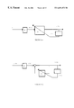
- FIG. 2 two architectures that outline the modeling of the mixing and the separation environments and processes are shown.
- the architecture in FIG. 2 ( a ) necessarily computes the inverse of the constant mixing matrix A, which requires that A is invertible, i.e., A ⁇ 1 exists.
- S(t) is the set of unknown sources
- M(t) is the set of mixtures
- U(t) is the set of separated signals that estimate S(t)
- Y(t) is the set of control signals used to update the parameters of the unmixing process.
- the weight update utilizes a function of the output U(t).
- the unmixing matrix W we labeled the unmixing matrix W, and in the second case we labeled it D.
- D has zero diagonal entries.
- the update of the entries of these two matrices is defined by the criteria used for signal separation, discrimination or recovery, e.g., information maximization, minimization of higher order cumulants, etc.
- ⁇ dot over (w) ⁇ ij ⁇ [W ⁇ T +g ′′( u )/ g ′( u ) M T ] ij Equation (4)
- Equation (4) One uses Equation (4) to update the entries of W in Equation (3). Through this is an iterative update procedure, the entries of W converge so that the product WA is nearly equal to the identity matrix or a permutation of the identity matrix.
- the dynamic mixing model accounts for more realistic mixing environments, defines such environment models and develops an update law to recover the original signals within this framework.
- Equation (8) This facilitates the computation by initializing the differential equation in Equation (8) from an arbitrary guess. It is important however to ensure the separation of time scales between Equations (8) and the update procedure like the one defined by Equation (6). This may be ensured by making ⁇ in Equation (6) and ⁇ in Equation (8) sufficiently small.
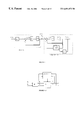
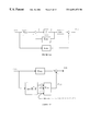
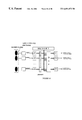
- FIG. 3 is a pictorial illustration of the dynamic model in feedback configuration.
- the adaptive separation procedure applies the adaptation functions and criteria to each element of the measured mixed signals individually and instantaneously, after which appropriate parameter updates are made.
- Equation (3) The second type of procedure has been described in FIG. 2 ( a ) that uses Equation (3).
- the criteria is applied to the entire data set, or selected data points from the entire data set.
- the related adaptation process does not progress per sample, but utilizes the whole data set over which a constant, static mixing matrix is assumed to apply.
- this method is somewhat more robust than the first, it is essentially an off-line method not suitable for real time signal separation. Furthermore, when the assumption of a static constant matrix is incorrect, the accuracy of the unmixing process suffers.
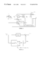
- the architecture is shown in FIG. 7 .
- the mixing environment may be described by the Linear Time-Invariant (LTI) state space:
- the parameter matrices ⁇ overscore (A) ⁇ , ⁇ overscore (B) ⁇ , ⁇ overscore (C) ⁇ and ⁇ overscore (D) ⁇ are of compatible dimensions.
- This formulation encompasses both continuous-time and discrete-time dynamics
- the dot on the state ⁇ overscore (X) ⁇ means derivative for continuous-time dynamics, it however means “advance” for discrete-time dynamics.
- the mixing environment is assumed to be (asymptotically) stable, i.e., the matrix ⁇ overscore (A) ⁇ has its eigenvalues in the left half complex plane.
- the (adaptive) network is proposed to be of the form
- FIG.(7) depicts the feedforward form of this framework.
- the matrices A*, B*, and C* can take on a family of values due to the nonsingular state-equivalent transformation T.
- T we shall use T to render the network architecture “canonical” or simple from a realization view point.
- This formulation in effect generalizes the formulations in the literature, which are limited to FIR filters, predominantly for 2-dimensional sources and two measurements, into general n-dimensional sources, and m-dimensional measurements. Note that, this modeling includes the FIR filtering models, and extends to IIR filtering if A is nonzero.
- the initial conditions can not be defined since the formulation is not in the time domain and can not be initialized with arbitrary initial conditions. Hence, the method is not suitable for real time or on line signal separation.
- the present invention describes a signal processing system for separating a plurality of input signals into a plurality of output signals, the input signals being composed of a function of a plurality of source signals being associated with a plurality of sources, the output signals estimating the source signals or functions of source signals.
- the system comprises a plurality of sensors for detecting the input signals, an architecture processor for defining and computing a signal separation method, the signal separation method delimiting a signal separation architecture for computing the output signals, and an output processor for computing the output signals based on the signal separation method or architecture.
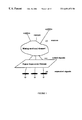
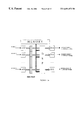
- FIG. 1 Signal separation, discrimination and recovery problem statement.
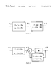
- FIG. 2 Architecture of the signal separation and recovery network in case of static mixing by matrix A.
- U(t) is the output which approximates the original source signals s(t).
- Y(t) contain the values that are used in updating the parameters of the unmixing processes, i.e., W in (a) and D in (b).
- FIG. 2 ( a ) A static neural network structure for signal separation.
- U(t) approximates S(t).
- Y(t) is used for weight update of the network.
- FIG. 2 ( b ) An alternate static neural network structure for signal separation.
- U(t) approximates S(t).
- Y(t) is used for weight update of the feedback network.
- FIG. 3 Architecture of the signal separation and recovery network in case of feedback dynamic mixing and separation models.
- U(t) approximates S(t).
- the function g defines the criteria used for weight update of the feedback network.
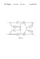
- FIG. 4 (a) Conventional transfer function representation for signal mixing and separation for a two signal system. The two signals U 1 and U 2 approximate S 1 and S 2 . G inverts the mixing process modeled as H. (b) The method is described only in two dimensions. The computation procedure and is neither practical nor extendible in the case of higher dimensional signals. Furthermore, the extension of the mixing environment to transfer function domain has also eliminated the time domain nature of the signals. This also causes the exclusion of the initial conditions from the set of equations.
- FIG. 5 Two mixing models for the state space time domain architecture.
- FIG. 6 Signal separation model for the state space time domain architecture.
- FIG. 7 Feedforward state space architecture.
- FIG. 8 Feedback state space architecture.
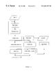
- FIGS. 9 ( a ) Flowchart of the method of the present invention.
- AID stands for analog to digital conversion, and D/A for digital to analog conversion.
- the internals of the DSP may include a variety of functional units as shown below. Different configurations are possible depending on the nature of the application, number of mixtures, desired accuracy, etc.
- FIG. 10 Audio application based on the signal separation and recovery procedures of this invention.
- Audio signals are converted electrical signals by the elements of the microphone array.
- Each element of the microphone array receives a different version (or mixture) of the sounds in the environment. Different arrangements of microphone elements can be designed depending on the nature of the application, number of mixtures, desired accuracy, and other relevant criteria.
- these mixture signals are converted from analog format to digital format, so that they can be stored and processed.
- the digital signal processor of the system is programmed in accordance with the procedures for signal separation and recovery procedures of this invention.
- the internals of the DSP may include a variety of functional units for various arithmetic and logic operations, and digital representation, data storage and retrieval means to achieve optimum performance. Circuits and structures shown in figure may undergo further integration towards realization of the whole system on a single to chip.
- the present invention seeks to recover and separate mixed signals transmitted through various media wherein the separation of signals is of such high quality as to substantially increase (i) the signal carrying capacity of the medium or channel, (ii) the quality of the received signal, or (iii) both.
- the media or channels may include a combination of wires, cables, fiber optics, wireless radio or light based frequencies or bands, as well as a combination of solid, liquid, gas particles, or vacuum.
- the present invention also seeks to separate mixed signals through media or channel wherein a high quality of signal separation is achieved by hardware currently available or produceable by state of the art techniques.
- the system of this invention introduces a set of generalized frameworks superior to the described preexisting approaches for coping with a range of circumstances unaddressed to date.
- the feedback state space architecture shown in FIG. 8 and its continuous and discrete renditions are described.
- the architecture is mapped onto a set of adaptive filters in both FIR and IIR form, commonly used by those skilled in the art of digital signal processing.
- many functions and procedures for the adaptive computation of parameters pertinent to the architectures of this invention are outlined. Both the architectures and the procedures for adaptive computation of parameters are designed for achieving on-line real time signal separation, discrimination and recovery.
- the most practically pertinent shortfalls of many other techniques namely the failure to account for multiple or unknown number of signals in the mixing, noise generation, changing mixing conditions, varying signal strength and quality, and some nonlinear phenomena are addressed by the formulations of this invention.
- the invented method overcomes the deficiencies of other methods by extending the formulation of the problem to include two new sets of architectures and frameworks, as well as a variety of parameter adaptation criteria and procedures designed for separating and recovering signals from mixtures.
- This invention presents a framework that addresses the blind signal separation and recovery (or de-convolution) in dynamic environments.
- the original work was motivated by the work of Herault and Jutten and Comon. Most of the recent results have focused primary on establishing analytical foundation of the results reported by Herault, Jutten and Kullback.
- Several researchers have used a host of analytical tools that include applied mathematics, statistical signal processing, system theory, dynamical systems and neural networks. The challenge still exists in generalizing the environment to more general dynamic systems.
- the emphasis of our method is in developing the network architecture, and the improved convergent algorithms, with a view towards efficient implementations.
- An improved approximation of the (nonlinear) mutual information/entropy function is used in order to ensure whitening and also to eliminate the assumption of output unit covariance.
- the improved expansion produces an odd polynomial in the network outputs which includes a linear term, as well as higher order terms—all absent from the expansion in other methods. It should be noted however, that some work has addressed only the static case where the mixing environment is represented by a constant matrix. Specifically, a formulation for an FIR filter was also converted into a static matrix mixing problem.
- FIG. 9 ( a ) shows a process flow diagram of a method of the present invention. This includes (1) obtaining samples, (2) pre-processing of the samples. (3) computing outputs using the present value of the states or adaptive parameters, (4) computing adaptive parameters, (5) computing internal states, and storing and/or presenting of outputs.
- Obtaining samples includes obtaining the multi channel data recorded through multiple sensors, e.g., microphones. Such data could also come from previously recorded outputs of said multiple sensors or mixtures thereof, e.g., mixed tracks of sounds. Data can be sampled on line for a real time or near real time process, or be recalled from a storage or recording media, e.g., tape, hard disk drive, etc.
- Preprocessing of the samples include various processing techniques for manipulation of the obtained samples, including but not limited to up or down sampling to vary the effective sampling rate of data, application of various frequency filters, e.g., low, high, or band pass filters, or notch filters, linear or nonlinear operations between sensor outputs of the present or previous samples, e.g., weighted sum of two or more sensors, buffering, random, pseudorandom or deterministic selection and buffering, windowing of sampled data or functions of sampled data, and various linear and nonlinear transforms of the sampled data.
- various frequency filters e.g., low, high, or band pass filters, or notch filters
- linear or nonlinear operations between sensor outputs of the present or previous samples e.g., weighted sum of two or more sensors, buffering, random, pseudorandom or deterministic selection and buffering, windowing of sampled data or functions of sampled data, and various linear and nonlinear transforms of the sampled data.
- Computing outputs uses the states and parameters computed earlier. It is also possible delay this step until after the computation of adaptive parameters or after the computation of the internal states, or both. Moreover, alternately, outputs could be computed twice per sample set.
- Computing of adaptive parameters may involve a method or multiple methods which use the derivatives of a function to compute the value of the function, the function defining the constraints imposed on the adaptive parameters. One or more such constraints can be used. A variety of methods and criteria specifically for computation of adaptive parameters are outlined in the present invention.
- the internal states may be in the form of a vector of states, scalar states, their samples in time, or their derivatives.
- the particular architecture defines the number of states.
- Dynamic models encompass and describe more realistic environments. Both feedforward and feedback architectures of the state space approach can be implemented. Feedforward linear state space architecture was listed above. Throughout this description, we shall refer to the mathematical model for signal mixing as the mixing environment, while we refer to the mathematical model for the signal recovery as the (adaptive) network.
- the method of this invention extends the environment to include more realistic models beyond a constant matrix, and develops successful update laws.
- a crucial first step is to include dynamic linear systems of the state space which are more general than FIR filters and transfer functions due to the inclusion of feedback and variations in initial conditions.
- these models lend themselves to direct extension to nonlinear models.
- Another motivation of this work is to enable eventual implementation in analog or mixed mode micro-electronics.
- the formulation addresses the feedback dynamic structures, where the environment is represented by a suitable realization of a dynamic linear system.
- the feedforward state space architecture was described in the introduction section and illustrated in FIG. 7 .
- H in the forward path of the network may in general represent a matrix in the simplest case, or a transfer function of a dynamic model.
- H may be chosen to be the identity matrix.
- nonlinearity as part of the architecture—explicitly.
- One model is to include nonlinearity as a static mapping of the measurement variable M(t).
- the adaptive network needs to include a compensating nonlinearity at its input stage.
- the input must include an “inverse-type” nonlinearity to counter act the measurement prior to further processing.
- This type of mixing environment is encountered in wireless applications that include satellite platforms.
- the mutual information of a random vector y is a measure of dependence among its components and is defined as follows:
- L(y) is the probability density function (pdf) of the random vector y
- p y j (y j ) is the probabilty density of the j-th component of the output vector v.
- the functional L(y) is always non-negative and is zero if and only if the components of the random vector y are statistically independent. This important measure defines the degree of dependence among the components of the signal vector. Therefore, it represents an appropriate functional for characterizing (the degree of) statistical independence.
- H(y): ⁇ E[ln f y ], is the entropy of y, and E[ ⁇ ] denotes the expected value.
- s(k) is an n-dimensional vector of original sources
- m(k) is the m-dimensional vector of measurements
- X p (k) is the N p -dimensional state vector.
- the vector (or matrix) w 1 * represents constant/parameter of the dynamic equation
- w 2 * represents constant/parameter of the “output” equation.
- the functions f p ( ⁇ ) and g p ( ⁇ ) are differentiable. It is also assumed that existence and uniqueness of solutions of the differential equation are satisfied for each set of initial conditions X p (t 0 ) and a given waveform vector s(k).
- the (processing) network may be represented by a dynamic (forward) network or a dynamic feedback network.
- the Feedforward Network is
- k is the index
- m(k) is the m-dimensional measurement
- y(k) is the r-dimensional output vector
- X(k) is the N-dimensional state vector.
- N and N p may be different.
- the vector (or matrix) w 1 represents the parameter of the dynamic equation
- w 2 represents the parameter of the “output” equation.
- the functions f( ⁇ ) and g( ⁇ ) are differentiable. It is also assumed that existence and uniqueness of solutions of the differential equation are satisfied for each set of initial conditions X(t 0 ) and a given measurement waveform vector m(k).
- the update law is now developed for dynamic environments to recover the original signals.
- the environment here is modeled as a linear dynamical system. Consequently, the network will also be modeled as a linear dynamical system.
- the network is a feedforward dynamical system.
- X k+1 f k ( X k ,m k ,w 1 ), X k 0
- this form of a general nonlinear time varying discrete dynamic model includes both the special architectures of multilayered recurrent and feedforward neural networks with any size and any number of layers. It is more compact, mathematically, to discuss this general case but its direct and straightforward specialization to feedforward and recurrent (feedback) models is strongly noted.
- H k L k ( y ( k ))+ ⁇ k+1 T f k ( X,m,w 1 )
- the boundary conditions are as follows: the first equation, the state equation, uses an initial condition, while the second equation, the co-state equation, uses a final condition equal to zero.
- the parameter equations use initial values with small norm which may be chosen randomly or from a given set.
- ⁇ overscore (X) ⁇ p ( k +1) ⁇ overscore (A) ⁇ overscore (X) ⁇ p ( k )+ ⁇ overscore (B) ⁇ s ( k )
- the first question is the following: Does there exist parameter matrices of the processing network which would recover the original signals? The answer is yes, the explicit solutions of the parameters are given next.
- m(k) is the m-dimensional vector of measurements
- y(k) is the n-dimensional vector of (processed) outputs
- X(k) is the (mL) dimensional states (representing filtered versions of the measurements in this case).
- each block sub-matrix A tj may be simplified to a diagonal matrix, and each I is a block identity matrix with appropriate dimensions.
- X 2 ⁇ ( k + 1 ) ⁇ X 1 ⁇ ( k )
- X L ⁇ ( k + 1 ) ⁇ X L - 1 ⁇ ( k )
- This model represents an IIR filtering structure of the measurement vector m(k). In the event that the block matrices A ti are zero, then the model is reduced to the special case of an FIR filter.
- This last equation relates the measured signal m(k) and its delayed versions represented by X j (k), to the output y(k).
- I is a matrix composed of the r ⁇ r identity matrix augmented by additional zero row (if n>r) or additional zero columns (if n ⁇ r).
- ( ⁇ I) may be replaced by time windowed averages of the diagonals of the f(y(k))g T (y(k)) matrix.
- a specific update can be performed simply by means of adding the rate of change ⁇ W to W as
- This invention introduces a set of update laws and links minimization of mutual information and the information maximization of the output entropy function of a nonlinear neural network, specifically in relation to techniques for blind separation, discrimination and recovery of mixed signals.
- the system of the invention enables the adaptive blind separation and recovery of several unknown signals mixed together in changing interference environments with very minimal assumption on the original signals.
- the mutual information of a random vector y is a measure of dependence among its components and is defined as follows:
- L(y) is the probability density function (pdf) of the random vector y
- p y (y j ) is the probabilty density of the j-th component of the output vector y.
- the functional L(y) is always non-negative and is zero if and only if the components of the random vector y are statistically independent. This important measure defines the degree of dependence among the components of the signal vector. Therefore, it represents an appropriate functional for characterizing (the degree of) statistical independence.
- H(y): ⁇ E[ln f y ], is the entropy of y, and E[ ⁇ ] denotes the expected value.
- the algorithm defined by the previous two equations converges when a uniform random noise and sine function are applied as unknown sources.
- One can use the natural gradient to express the update law defined previously as ⁇ dot over (W) ⁇ ⁇ [W ⁇ T ⁇ f a (y)M T ] as
- the update law is now developed for dynamic environments to recover the original signals.
- the environment here is modeled as a linear dynamical system. Consequently, the network will also be modeled as a linear dynamical system.
- the network is a feedforward dynamical system as in FIG. 7 .
- the performance index J ⁇ ( x , w ) ⁇ 0 T ⁇ L ⁇ ( t , x , x . , ⁇ , w ) ⁇ ⁇ ⁇ t
- the functional ⁇ may represent a scaled version of our measure of dependence I(y), w is a vector constructed of the rows of the parameter matrices C and D. Note that a canonical realization may be used so that B is constant.
- the matrix A, in the canonical representation, may have only N-parameters, where N is the dimension of the state vector X.
- f a ( ⁇ ) is given by a variety of nonlinear expansive odd-functions which include hyperbolic sine, and the inverse of a sigmiodal function.
- the (output) feedback architecture of FIG. 8 may be simplified in realization with the following (canonical) state-space representation:
- each X i represents a state vector of the environment of the same dimension as the source signals
- each X i represents a state of the network of the same dimension as the output signal.
- L the same number, of the state vectors in both environment and network.
- the states may, in the simple FIR filtering, represent simple delays of the sources, while the states in the network represent delays in the fed back output signals.
- this view is a simple consideration of the delays of the signal that occur in real physical applications.
- the framework therefore, is more general since it may consider arbitrary delays including those of IIR filtering and continuous-time physical effects.
- I ⁇ ( y ) E ⁇ [ ln ⁇ ⁇ f M ⁇ ( u ) ⁇ W ⁇ ⁇ ⁇ i ⁇ f yi ⁇ ( u i ) ] ⁇ f y ⁇ ⁇ ( u ) ⁇ ln ⁇ ⁇ f M ⁇ ( u ) ⁇ W ⁇ ⁇ ⁇ i ⁇ f yi ⁇ ( u i ) ⁇ ⁇ ⁇ u ⁇
- DSP architectures For a DSP based emulation of the signal separation algorithm families discussed here, it will be up to the tradeoffs in a particular application to identify the best processor architecture and numerical representations, e.g., floating or fixed point. To achieve a highly integrated solution (e.g., one chip) will require embedding a DSP core either from a pre-designed device or designed from standard silicon cell libraries.
- the compiler front-end to the DSP assembler and linker forms a direct bridge from a high level language coded algorithm simulation environment to DSP emulation.
- a similar direct link exists between many computing environments and the DSP emulation environments, for example, C/C++ library and compilers for various processors.
- Programmable logic can be an integral part of the related development process.
- a programmable DSP core (a DSP processor that is designed for integration into a custom chip) can be integrated with custom logic to differentiate a system and reduce system cost, space, and power consumption.
Abstract
Description


Claims (31)


Priority Applications (1)
| Application Number | Priority Date | Filing Date | Title |
|---|---|---|---|
| US09/701,920 US6691073B1 (en) | 1998-06-18 | 1999-06-16 | Adaptive state space signal separation, discrimination and recovery |
Applications Claiming Priority (3)
| Application Number | Priority Date | Filing Date | Title |
|---|---|---|---|
| US8975098P | 1998-06-18 | 1998-06-18 | |
| PCT/US1999/013550 WO1999066638A1 (en) | 1998-06-18 | 1999-06-16 | Adaptive state space signal separation, discrimination and recovery architectures and their adaptations for use in dynamic environments |
| US09/701,920 US6691073B1 (en) | 1998-06-18 | 1999-06-16 | Adaptive state space signal separation, discrimination and recovery |
Publications (1)
| Publication Number | Publication Date |
|---|---|
| US6691073B1 true US6691073B1 (en) | 2004-02-10 |
Family
ID=30772413
Family Applications (1)
| Application Number | Title | Priority Date | Filing Date |
|---|---|---|---|
| US09/701,920 Expired - Lifetime US6691073B1 (en) | 1998-06-18 | 1999-06-16 | Adaptive state space signal separation, discrimination and recovery |
Country Status (1)
| Country | Link |
|---|---|
| US (1) | US6691073B1 (en) |
Cited By (46)
| Publication number | Priority date | Publication date | Assignee | Title |
|---|---|---|---|---|
| US20010036284A1 (en) * | 2000-02-02 | 2001-11-01 | Remo Leber | Circuit and method for the adaptive suppression of noise |
| US20040014445A1 (en) * | 2000-06-16 | 2004-01-22 | Simon Godsill | Method for extracting a signal |
| WO2004038562A2 (en) * | 2002-10-23 | 2004-05-06 | Hynomics Corporation | Methods and system for generic optimization of control functions |
| US20050021333A1 (en) * | 2003-07-23 | 2005-01-27 | Paris Smaragdis | Method and system for detecting and temporally relating components in non-stationary signals |
| US20050196098A1 (en) * | 2001-03-02 | 2005-09-08 | Fujitsu Limited | Optical switch |
| US20050213778A1 (en) * | 2004-03-17 | 2005-09-29 | Markus Buck | System for detecting and reducing noise via a microphone array |
| US20060265088A1 (en) * | 2005-05-18 | 2006-11-23 | Roger Warford | Method and system for recording an electronic communication and extracting constituent audio data therefrom |
| US20060265090A1 (en) * | 2005-05-18 | 2006-11-23 | Kelly Conway | Method and software for training a customer service representative by analysis of a telephonic interaction between a customer and a contact center |
| US20060262919A1 (en) * | 2005-05-18 | 2006-11-23 | Christopher Danson | Method and system for analyzing separated voice data of a telephonic communication between a customer and a contact center by applying a psychological behavioral model thereto |
| US20060265089A1 (en) * | 2005-05-18 | 2006-11-23 | Kelly Conway | Method and software for analyzing voice data of a telephonic communication and generating a retention strategy therefrom |
| US20060262920A1 (en) * | 2005-05-18 | 2006-11-23 | Kelly Conway | Method and system for analyzing separated voice data of a telephonic communication between a customer and a contact center by applying a psychological behavioral model thereto |
| WO2007020452A1 (en) * | 2005-08-19 | 2007-02-22 | University Of Plymouth Enterprise | Method and apparatus for configuring a communication channel |
| US20070098119A1 (en) * | 2003-05-14 | 2007-05-03 | Ian Stothers | Adaptive control unit with feedback compensation |
| US20070121974A1 (en) * | 2005-11-08 | 2007-05-31 | Think-A-Move, Ltd. | Earset assembly |
| US20070177695A1 (en) * | 2004-03-31 | 2007-08-02 | Board Of Trustees Of Michigan State University | Multi-user detection in cdma systems |
| US20070253574A1 (en) * | 2006-04-28 | 2007-11-01 | Soulodre Gilbert Arthur J | Method and apparatus for selectively extracting components of an input signal |
| US20070258353A1 (en) * | 2004-12-03 | 2007-11-08 | Nec Corporation | Method and Apparatus for Blindly Separating Mixed Signals, and a Transmission Method and Apparatus of Mixed |
| US20070291953A1 (en) * | 2006-06-14 | 2007-12-20 | Think-A-Move, Ltd. | Ear sensor assembly for speech processing |
| US20080069366A1 (en) * | 2006-09-20 | 2008-03-20 | Gilbert Arthur Joseph Soulodre | Method and apparatus for extracting and changing the reveberant content of an input signal |
| US20080240404A1 (en) * | 2007-03-30 | 2008-10-02 | Kelly Conway | Method and system for aggregating and analyzing data relating to an interaction between a customer and a contact center agent |
| US20080240405A1 (en) * | 2007-03-30 | 2008-10-02 | Kelly Conway | Method and system for aggregating and analyzing data relating to a plurality of interactions between a customer and a contact center and generating business process analytics |
| US20080240374A1 (en) * | 2007-03-30 | 2008-10-02 | Kelly Conway | Method and system for linking customer conversation channels |
| US20080240376A1 (en) * | 2007-03-30 | 2008-10-02 | Kelly Conway | Method and system for automatically routing a telephonic communication base on analytic attributes associated with prior telephonic communication |
| US20090034756A1 (en) * | 2005-06-24 | 2009-02-05 | Volker Arno Willem F | System and method for extracting acoustic signals from signals emitted by a plurality of sources |
| US20090103709A1 (en) * | 2007-09-28 | 2009-04-23 | Kelly Conway | Methods and systems for determining and displaying business relevance of telephonic communications between customers and a contact center |
| US7542815B1 (en) * | 2003-09-04 | 2009-06-02 | Akita Blue, Inc. | Extraction of left/center/right information from two-channel stereo sources |
| US20090171874A1 (en) * | 2005-08-19 | 2009-07-02 | University Of Plymouth Enterprise | Method and apparatus for configuring a communication channel |
| US20110054638A1 (en) * | 2006-10-18 | 2011-03-03 | National University Corporation NARA Institute of Science and Technology | Remote control system |
| US20110081024A1 (en) * | 2009-10-05 | 2011-04-07 | Harman International Industries, Incorporated | System for spatial extraction of audio signals |
| US8023639B2 (en) | 2007-03-30 | 2011-09-20 | Mattersight Corporation | Method and system determining the complexity of a telephonic communication received by a contact center |
| US8131541B2 (en) | 2008-04-25 | 2012-03-06 | Cambridge Silicon Radio Limited | Two microphone noise reduction system |
| US20120259561A1 (en) * | 2011-04-05 | 2012-10-11 | The Regents Of The University Of California | Apparatus and method for signal extraction and separation |
| EP1686831A3 (en) * | 2005-01-26 | 2012-10-31 | Sony Corporation | Apparatus and method for separating audio signals |
| US8938078B2 (en) | 2010-10-07 | 2015-01-20 | Concertsonics, Llc | Method and system for enhancing sound |
| US9083801B2 (en) | 2013-03-14 | 2015-07-14 | Mattersight Corporation | Methods and system for analyzing multichannel electronic communication data |
| WO2018000330A1 (en) * | 2016-06-30 | 2018-01-04 | 张升泽 | Method and system for preprocessing signal of electronic chip |
| US10162378B1 (en) * | 2015-03-19 | 2018-12-25 | Hrl Laboratories, Llc | Neuromorphic processor for wideband signal analysis |
| US20190109581A1 (en) * | 2017-10-05 | 2019-04-11 | King Fahd University Of Petroleum And Minerals | Adaptive filter method, system and apparatus |
| US10380062B1 (en) | 2015-03-19 | 2019-08-13 | Hrl Laboratories, Llc | Efficient cognitive signal denoising with sparse output layers |
| US10404299B1 (en) | 2016-03-07 | 2019-09-03 | Hrl Laboratories, Llc | System for parallelized cognitive signal denoising |
| US10712425B1 (en) | 2015-03-19 | 2020-07-14 | Hrl Laboratories, Llc | Cognitive denoising of nonstationary signals using time varying reservoir computer |
| US10720949B1 (en) | 2015-03-19 | 2020-07-21 | Hrl Laboratories, Llc | Real-time time-difference-of-arrival (TDOA) estimation via multi-input cognitive signal processor |
| CN112202529A (en) * | 2020-09-27 | 2021-01-08 | 中国电子科技集团公司第三十六研究所 | Wireless communication information recovery method and device and electronic equipment |
| US10921422B2 (en) * | 2017-10-25 | 2021-02-16 | The Boeing Company | Below-noise after transmit (BAT) Chirp Radar |
| US11002819B2 (en) | 2018-04-24 | 2021-05-11 | The Boeing Company | Angular resolution of targets using separate radar receivers |
| CN113836483A (en) * | 2021-08-10 | 2021-12-24 | 中国地质大学(武汉) | Deep non-negative matrix unmixing method based on information entropy sparseness and storage medium |
Citations (10)
| Publication number | Priority date | Publication date | Assignee | Title |
|---|---|---|---|---|
| US5140670A (en) | 1989-10-05 | 1992-08-18 | Regents Of The University Of California | Cellular neural network |
| US5208786A (en) | 1991-08-28 | 1993-05-04 | Massachusetts Institute Of Technology | Multi-channel signal separation |
| US5355528A (en) | 1992-10-13 | 1994-10-11 | The Regents Of The University Of California | Reprogrammable CNN and supercomputer |
| US5383164A (en) | 1993-06-10 | 1995-01-17 | The Salk Institute For Biological Studies | Adaptive system for broadband multisignal discrimination in a channel with reverberation |
| US5539832A (en) | 1992-04-10 | 1996-07-23 | Ramot University Authority For Applied Research & Industrial Development Ltd. | Multi-channel signal separation using cross-polyspectra |
| US5706402A (en) | 1994-11-29 | 1998-01-06 | The Salk Institute For Biological Studies | Blind signal processing system employing information maximization to recover unknown signals through unsupervised minimization of output redundancy |
| WO1998058450A1 (en) | 1997-06-18 | 1998-12-23 | Clarity, L.L.C. | Methods and apparatus for blind signal separation |
| WO1999066638A1 (en) | 1998-06-18 | 1999-12-23 | Clarity, Llc | Adaptive state space signal separation, discrimination and recovery architectures and their adaptations for use in dynamic environments |
| US6185309B1 (en) * | 1997-07-11 | 2001-02-06 | The Regents Of The University Of California | Method and apparatus for blind separation of mixed and convolved sources |
| US6389445B1 (en) * | 1995-08-31 | 2002-05-14 | The Trustees Of Columbia University In The City Of New York | Methods and systems for designing and making signal-processor circuits with internal companding, and the resulting circuits |
-
1999
- 1999-06-16 US US09/701,920 patent/US6691073B1/en not_active Expired - Lifetime
Patent Citations (10)
| Publication number | Priority date | Publication date | Assignee | Title |
|---|---|---|---|---|
| US5140670A (en) | 1989-10-05 | 1992-08-18 | Regents Of The University Of California | Cellular neural network |
| US5208786A (en) | 1991-08-28 | 1993-05-04 | Massachusetts Institute Of Technology | Multi-channel signal separation |
| US5539832A (en) | 1992-04-10 | 1996-07-23 | Ramot University Authority For Applied Research & Industrial Development Ltd. | Multi-channel signal separation using cross-polyspectra |
| US5355528A (en) | 1992-10-13 | 1994-10-11 | The Regents Of The University Of California | Reprogrammable CNN and supercomputer |
| US5383164A (en) | 1993-06-10 | 1995-01-17 | The Salk Institute For Biological Studies | Adaptive system for broadband multisignal discrimination in a channel with reverberation |
| US5706402A (en) | 1994-11-29 | 1998-01-06 | The Salk Institute For Biological Studies | Blind signal processing system employing information maximization to recover unknown signals through unsupervised minimization of output redundancy |
| US6389445B1 (en) * | 1995-08-31 | 2002-05-14 | The Trustees Of Columbia University In The City Of New York | Methods and systems for designing and making signal-processor circuits with internal companding, and the resulting circuits |
| WO1998058450A1 (en) | 1997-06-18 | 1998-12-23 | Clarity, L.L.C. | Methods and apparatus for blind signal separation |
| US6185309B1 (en) * | 1997-07-11 | 2001-02-06 | The Regents Of The University Of California | Method and apparatus for blind separation of mixed and convolved sources |
| WO1999066638A1 (en) | 1998-06-18 | 1999-12-23 | Clarity, Llc | Adaptive state space signal separation, discrimination and recovery architectures and their adaptations for use in dynamic environments |
Non-Patent Citations (13)
| Title |
|---|
| A. Chihocki, et al.; Adaptive Approach to Blind Source Separation with Cancellation of Additive and Convolutional Noise; 3rd. International Conference on Signal Processing; 1996, vol. 1; pp 412-415. |
| A.J. Bell, et al.; Blind Separation and Blind Deconvolution; An Information-Theoretic Approach; 1995 International Conference on Acoustics, Speech, and Signal Processing; ICASSP-95; vol. 5; pp. 3415-3418. |
| C. Jutten and J. Herault; Blind Separation of Sources, Part 1: An adaptive algorithm based on neuromimetic architecture; Signal Processing, vol. 24, No. 1, Jul. 1991, pp. 1-10. |
| C. Jutten and J. Herault; Blind Separation of Sources, Part II: Problems Statement; Signal Processing, vol. 24, No. 1, Jul. 1991, pp. 11-20. |
| E. Weinstein, et al.; Multi-Channel Signal Separation by Decorrelation; IEEE Transactions on Speech and Audio Processing, vol. 1, No. 4, Oct. 1993 pp. 405-413. |
| F.M. Salam; An Adaptive Network for Blind Separation of Independent Signals; Proceedings of the 1993 IEEE International Symposium on Circuits and Systems (ISCAS) vol. 1, pp. 431-434. |
| FM Salam and G. Erten; Blind Signal Separation and Recovery in Dynamic Environments; NSIP 97 Workshop; Mackinac Island, Michigan, USA, in Sep. 1997. |
| G. Erten and F. Salam; "Modified Cellular Neural Network Architecture for Integrated Image Sensing and Processing"; Proceedings of the 1999 IEEE International Symposium on Circuits and Systems, vol. 5, Orlando, Florida, May 30-Jun. 2, 1999; pp. 120-123. |
| G. Erten and F. Salam; "Two Cellular Architectures for Integrated Image Sensing and Processing on a Single Chip"; Journal of Circuits, Systems and Computers, vol. 8, Nos. 5 & 6; 1998, pp. 637-659. |
| G. Erten and F. Salam; Real Time Separation of Audio Signals Using Digital Signal Processors; MWSCAS 1997 Sacramento, California; IEEE 1997; pp 1237-1240. |
| Gilbert, State Space and ARMA Models: An Overview of the Equivalence, Mar. 1993, pp. 1-26.* * |
| Hoang-Lan Nguyen Thi and Christian Jutten; "Blind Source Separation for Convolutive Mixtures"; Signal Processing European Journal Devoted to the Methods and Applications of Signal Processing; vol. 45, No. 2; Aug. 1, 1995; pp. 209-229. |
| Marven et al., A Simple Approach to Digital Signal Processing, 1996, John Wiley & Sons, Inc., pp. 90-102.* * |
Cited By (107)
| Publication number | Priority date | Publication date | Assignee | Title |
|---|---|---|---|---|
| US20010036284A1 (en) * | 2000-02-02 | 2001-11-01 | Remo Leber | Circuit and method for the adaptive suppression of noise |
| US6928171B2 (en) * | 2000-02-02 | 2005-08-09 | Bernafon Ag | Circuit and method for the adaptive suppression of noise |
| US7110722B2 (en) * | 2000-06-16 | 2006-09-19 | At&T Laboratories-Cambridge Limited | Method for extracting a signal |
| US20040014445A1 (en) * | 2000-06-16 | 2004-01-22 | Simon Godsill | Method for extracting a signal |
| US7379636B2 (en) | 2001-03-02 | 2008-05-27 | Fujitsu Limited | Optical switch |
| US7206476B2 (en) | 2001-03-02 | 2007-04-17 | Fujitsu Limited | Optical switch |
| US20050196098A1 (en) * | 2001-03-02 | 2005-09-08 | Fujitsu Limited | Optical switch |
| US20070098321A1 (en) * | 2001-03-02 | 2007-05-03 | Fujitsu Limited | Optical switch |
| WO2004038562A3 (en) * | 2002-10-23 | 2004-06-10 | Hynomics Corp | Methods and system for generic optimization of control functions |
| WO2004038562A2 (en) * | 2002-10-23 | 2004-05-06 | Hynomics Corporation | Methods and system for generic optimization of control functions |
| US8411872B2 (en) * | 2003-05-14 | 2013-04-02 | Ultra Electronics Limited | Adaptive control unit with feedback compensation |
| US20070098119A1 (en) * | 2003-05-14 | 2007-05-03 | Ian Stothers | Adaptive control unit with feedback compensation |
| US9183827B2 (en) | 2003-05-14 | 2015-11-10 | Ultra Electronics Limited | PID controller |
| US20050021333A1 (en) * | 2003-07-23 | 2005-01-27 | Paris Smaragdis | Method and system for detecting and temporally relating components in non-stationary signals |
| US7672834B2 (en) * | 2003-07-23 | 2010-03-02 | Mitsubishi Electric Research Laboratories, Inc. | Method and system for detecting and temporally relating components in non-stationary signals |
| US8086334B2 (en) | 2003-09-04 | 2011-12-27 | Akita Blue, Inc. | Extraction of a multiple channel time-domain output signal from a multichannel signal |
| US8600533B2 (en) | 2003-09-04 | 2013-12-03 | Akita Blue, Inc. | Extraction of a multiple channel time-domain output signal from a multichannel signal |
| US20090287328A1 (en) * | 2003-09-04 | 2009-11-19 | Akita Blue, Inc. | Extraction of a multiple channel time-domain output signal from a multichannel signal |
| US7542815B1 (en) * | 2003-09-04 | 2009-06-02 | Akita Blue, Inc. | Extraction of left/center/right information from two-channel stereo sources |
| US20050213778A1 (en) * | 2004-03-17 | 2005-09-29 | Markus Buck | System for detecting and reducing noise via a microphone array |
| US7881480B2 (en) | 2004-03-17 | 2011-02-01 | Nuance Communications, Inc. | System for detecting and reducing noise via a microphone array |
| US20110026732A1 (en) * | 2004-03-17 | 2011-02-03 | Nuance Communications, Inc. | System for Detecting and Reducing Noise via a Microphone Array |
| US9197975B2 (en) | 2004-03-17 | 2015-11-24 | Nuance Communications, Inc. | System for detecting and reducing noise via a microphone array |
| US8483406B2 (en) | 2004-03-17 | 2013-07-09 | Nuance Communications, Inc. | System for detecting and reducing noise via a microphone array |
| US20070177695A1 (en) * | 2004-03-31 | 2007-08-02 | Board Of Trustees Of Michigan State University | Multi-user detection in cdma systems |
| US20070258353A1 (en) * | 2004-12-03 | 2007-11-08 | Nec Corporation | Method and Apparatus for Blindly Separating Mixed Signals, and a Transmission Method and Apparatus of Mixed |
| US7760758B2 (en) * | 2004-12-03 | 2010-07-20 | Nec Corporation | Method and apparatus for blindly separating mixed signals, and a transmission method and apparatus of mixed signals |
| EP1686831A3 (en) * | 2005-01-26 | 2012-10-31 | Sony Corporation | Apparatus and method for separating audio signals |
| US20060262920A1 (en) * | 2005-05-18 | 2006-11-23 | Kelly Conway | Method and system for analyzing separated voice data of a telephonic communication between a customer and a contact center by applying a psychological behavioral model thereto |
| US8094803B2 (en) | 2005-05-18 | 2012-01-10 | Mattersight Corporation | Method and system for analyzing separated voice data of a telephonic communication between a customer and a contact center by applying a psychological behavioral model thereto |
| US9571650B2 (en) | 2005-05-18 | 2017-02-14 | Mattersight Corporation | Method and system for generating a responsive communication based on behavioral assessment data |
| US20080260122A1 (en) * | 2005-05-18 | 2008-10-23 | Kelly Conway | Method and system for selecting and navigating to call examples for playback or analysis |
| US20060265088A1 (en) * | 2005-05-18 | 2006-11-23 | Roger Warford | Method and system for recording an electronic communication and extracting constituent audio data therefrom |
| US20060265090A1 (en) * | 2005-05-18 | 2006-11-23 | Kelly Conway | Method and software for training a customer service representative by analysis of a telephonic interaction between a customer and a contact center |
| US9432511B2 (en) | 2005-05-18 | 2016-08-30 | Mattersight Corporation | Method and system of searching for communications for playback or analysis |
| US10021248B2 (en) | 2005-05-18 | 2018-07-10 | Mattersight Corporation | Method and system for analyzing caller interaction event data |
| US20060262919A1 (en) * | 2005-05-18 | 2006-11-23 | Christopher Danson | Method and system for analyzing separated voice data of a telephonic communication between a customer and a contact center by applying a psychological behavioral model thereto |
| US10104233B2 (en) | 2005-05-18 | 2018-10-16 | Mattersight Corporation | Coaching portal and methods based on behavioral assessment data |
| US10129402B1 (en) | 2005-05-18 | 2018-11-13 | Mattersight Corporation | Customer satisfaction analysis of caller interaction event data system and methods |
| US8594285B2 (en) | 2005-05-18 | 2013-11-26 | Mattersight Corporation | Method and system for analyzing separated voice data of a telephonic communication between a customer and a contact center by applying a psychological behavioral model thereto |
| US9357071B2 (en) | 2005-05-18 | 2016-05-31 | Mattersight Corporation | Method and system for analyzing a communication by applying a behavioral model thereto |
| WO2006125047A1 (en) * | 2005-05-18 | 2006-11-23 | Eloyalty Corporation | A method and system for recording an electronic communication and extracting constituent audio data therefrom |
| US8094790B2 (en) | 2005-05-18 | 2012-01-10 | Mattersight Corporation | Method and software for training a customer service representative by analysis of a telephonic interaction between a customer and a contact center |
| US9225841B2 (en) | 2005-05-18 | 2015-12-29 | Mattersight Corporation | Method and system for selecting and navigating to call examples for playback or analysis |
| US9692894B2 (en) | 2005-05-18 | 2017-06-27 | Mattersight Corporation | Customer satisfaction system and method based on behavioral assessment data |
| US20060265089A1 (en) * | 2005-05-18 | 2006-11-23 | Kelly Conway | Method and software for analyzing voice data of a telephonic communication and generating a retention strategy therefrom |
| US7995717B2 (en) | 2005-05-18 | 2011-08-09 | Mattersight Corporation | Method and system for analyzing separated voice data of a telephonic communication between a customer and a contact center by applying a psychological behavioral model thereto |
| US8781102B2 (en) | 2005-05-18 | 2014-07-15 | Mattersight Corporation | Method and system for analyzing a communication by applying a behavioral model thereto |
| US20090034756A1 (en) * | 2005-06-24 | 2009-02-05 | Volker Arno Willem F | System and method for extracting acoustic signals from signals emitted by a plurality of sources |
| US8438123B2 (en) | 2005-08-19 | 2013-05-07 | University Of Plymouth Enterprise Limited | Method and apparatus for configuring a communication channel |
| WO2007020452A1 (en) * | 2005-08-19 | 2007-02-22 | University Of Plymouth Enterprise | Method and apparatus for configuring a communication channel |
| CN101310459B (en) * | 2005-08-19 | 2012-03-21 | 普利茅斯事业大学 | Method and apparatus for configuring a communication channel |
| US20090171874A1 (en) * | 2005-08-19 | 2009-07-02 | University Of Plymouth Enterprise | Method and apparatus for configuring a communication channel |
| US7983433B2 (en) | 2005-11-08 | 2011-07-19 | Think-A-Move, Ltd. | Earset assembly |
| US20070121974A1 (en) * | 2005-11-08 | 2007-05-31 | Think-A-Move, Ltd. | Earset assembly |
| US20070253574A1 (en) * | 2006-04-28 | 2007-11-01 | Soulodre Gilbert Arthur J | Method and apparatus for selectively extracting components of an input signal |
| US8180067B2 (en) | 2006-04-28 | 2012-05-15 | Harman International Industries, Incorporated | System for selectively extracting components of an audio input signal |
| US20070291953A1 (en) * | 2006-06-14 | 2007-12-20 | Think-A-Move, Ltd. | Ear sensor assembly for speech processing |
| US7502484B2 (en) | 2006-06-14 | 2009-03-10 | Think-A-Move, Ltd. | Ear sensor assembly for speech processing |
| US20080232603A1 (en) * | 2006-09-20 | 2008-09-25 | Harman International Industries, Incorporated | System for modifying an acoustic space with audio source content |
| US20080069366A1 (en) * | 2006-09-20 | 2008-03-20 | Gilbert Arthur Joseph Soulodre | Method and apparatus for extracting and changing the reveberant content of an input signal |
| US8670850B2 (en) | 2006-09-20 | 2014-03-11 | Harman International Industries, Incorporated | System for modifying an acoustic space with audio source content |
| US9264834B2 (en) | 2006-09-20 | 2016-02-16 | Harman International Industries, Incorporated | System for modifying an acoustic space with audio source content |
| US8751029B2 (en) | 2006-09-20 | 2014-06-10 | Harman International Industries, Incorporated | System for extraction of reverberant content of an audio signal |
| US8036767B2 (en) | 2006-09-20 | 2011-10-11 | Harman International Industries, Incorporated | System for extracting and changing the reverberant content of an audio input signal |
| US20110054638A1 (en) * | 2006-10-18 | 2011-03-03 | National University Corporation NARA Institute of Science and Technology | Remote control system |
| US8280532B2 (en) * | 2006-10-18 | 2012-10-02 | National University Corporation NARA Institute of Science and Technology | Remote control system |
| US20080240376A1 (en) * | 2007-03-30 | 2008-10-02 | Kelly Conway | Method and system for automatically routing a telephonic communication base on analytic attributes associated with prior telephonic communication |
| US20080240374A1 (en) * | 2007-03-30 | 2008-10-02 | Kelly Conway | Method and system for linking customer conversation channels |
| US8983054B2 (en) | 2007-03-30 | 2015-03-17 | Mattersight Corporation | Method and system for automatically routing a telephonic communication |
| US10129394B2 (en) | 2007-03-30 | 2018-11-13 | Mattersight Corporation | Telephonic communication routing system based on customer satisfaction |
| US9124701B2 (en) | 2007-03-30 | 2015-09-01 | Mattersight Corporation | Method and system for automatically routing a telephonic communication |
| US8023639B2 (en) | 2007-03-30 | 2011-09-20 | Mattersight Corporation | Method and system determining the complexity of a telephonic communication received by a contact center |
| US20080240404A1 (en) * | 2007-03-30 | 2008-10-02 | Kelly Conway | Method and system for aggregating and analyzing data relating to an interaction between a customer and a contact center agent |
| US20080240405A1 (en) * | 2007-03-30 | 2008-10-02 | Kelly Conway | Method and system for aggregating and analyzing data relating to a plurality of interactions between a customer and a contact center and generating business process analytics |
| US8891754B2 (en) | 2007-03-30 | 2014-11-18 | Mattersight Corporation | Method and system for automatically routing a telephonic communication |
| US8718262B2 (en) | 2007-03-30 | 2014-05-06 | Mattersight Corporation | Method and system for automatically routing a telephonic communication base on analytic attributes associated with prior telephonic communication |
| US9270826B2 (en) | 2007-03-30 | 2016-02-23 | Mattersight Corporation | System for automatically routing a communication |
| US7869586B2 (en) | 2007-03-30 | 2011-01-11 | Eloyalty Corporation | Method and system for aggregating and analyzing data relating to a plurality of interactions between a customer and a contact center and generating business process analytics |
| US9699307B2 (en) | 2007-03-30 | 2017-07-04 | Mattersight Corporation | Method and system for automatically routing a telephonic communication |
| US20090103709A1 (en) * | 2007-09-28 | 2009-04-23 | Kelly Conway | Methods and systems for determining and displaying business relevance of telephonic communications between customers and a contact center |
| US10601994B2 (en) | 2007-09-28 | 2020-03-24 | Mattersight Corporation | Methods and systems for determining and displaying business relevance of telephonic communications between customers and a contact center |
| US10419611B2 (en) | 2007-09-28 | 2019-09-17 | Mattersight Corporation | System and methods for determining trends in electronic communications |
| US8131541B2 (en) | 2008-04-25 | 2012-03-06 | Cambridge Silicon Radio Limited | Two microphone noise reduction system |
| US20110081024A1 (en) * | 2009-10-05 | 2011-04-07 | Harman International Industries, Incorporated | System for spatial extraction of audio signals |
| US9372251B2 (en) | 2009-10-05 | 2016-06-21 | Harman International Industries, Incorporated | System for spatial extraction of audio signals |
| US8938078B2 (en) | 2010-10-07 | 2015-01-20 | Concertsonics, Llc | Method and system for enhancing sound |
| US20120259561A1 (en) * | 2011-04-05 | 2012-10-11 | The Regents Of The University Of California | Apparatus and method for signal extraction and separation |
| US9940546B2 (en) * | 2011-04-05 | 2018-04-10 | The Regents Of The University Of California | Apparatus and method for signal extraction and separation |
| US9191510B2 (en) | 2013-03-14 | 2015-11-17 | Mattersight Corporation | Methods and system for analyzing multichannel electronic communication data |
| US9407768B2 (en) | 2013-03-14 | 2016-08-02 | Mattersight Corporation | Methods and system for analyzing multichannel electronic communication data |
| US9083801B2 (en) | 2013-03-14 | 2015-07-14 | Mattersight Corporation | Methods and system for analyzing multichannel electronic communication data |
| US9942400B2 (en) | 2013-03-14 | 2018-04-10 | Mattersight Corporation | System and methods for analyzing multichannel communications including voice data |
| US10194029B2 (en) | 2013-03-14 | 2019-01-29 | Mattersight Corporation | System and methods for analyzing online forum language |
| US9667788B2 (en) | 2013-03-14 | 2017-05-30 | Mattersight Corporation | Responsive communication system for analyzed multichannel electronic communication |
| US10162378B1 (en) * | 2015-03-19 | 2018-12-25 | Hrl Laboratories, Llc | Neuromorphic processor for wideband signal analysis |
| US10720949B1 (en) | 2015-03-19 | 2020-07-21 | Hrl Laboratories, Llc | Real-time time-difference-of-arrival (TDOA) estimation via multi-input cognitive signal processor |
| US10380062B1 (en) | 2015-03-19 | 2019-08-13 | Hrl Laboratories, Llc | Efficient cognitive signal denoising with sparse output layers |
| US10712425B1 (en) | 2015-03-19 | 2020-07-14 | Hrl Laboratories, Llc | Cognitive denoising of nonstationary signals using time varying reservoir computer |
| US10404299B1 (en) | 2016-03-07 | 2019-09-03 | Hrl Laboratories, Llc | System for parallelized cognitive signal denoising |
| WO2018000330A1 (en) * | 2016-06-30 | 2018-01-04 | 张升泽 | Method and system for preprocessing signal of electronic chip |
| US20190109581A1 (en) * | 2017-10-05 | 2019-04-11 | King Fahd University Of Petroleum And Minerals | Adaptive filter method, system and apparatus |
| US10921422B2 (en) * | 2017-10-25 | 2021-02-16 | The Boeing Company | Below-noise after transmit (BAT) Chirp Radar |
| US11002819B2 (en) | 2018-04-24 | 2021-05-11 | The Boeing Company | Angular resolution of targets using separate radar receivers |
| CN112202529A (en) * | 2020-09-27 | 2021-01-08 | 中国电子科技集团公司第三十六研究所 | Wireless communication information recovery method and device and electronic equipment |
| CN112202529B (en) * | 2020-09-27 | 2022-11-08 | 中国电子科技集团公司第三十六研究所 | Wireless communication information recovery method and device and electronic equipment |
| CN113836483A (en) * | 2021-08-10 | 2021-12-24 | 中国地质大学(武汉) | Deep non-negative matrix unmixing method based on information entropy sparseness and storage medium |
Similar Documents
| Publication | Publication Date | Title |
|---|---|---|
| US6691073B1 (en) | Adaptive state space signal separation, discrimination and recovery | |
| Torkkola | Blind separation of convolved sources based on information maximization | |
| Lee et al. | Blind source separation of real world signals | |
| US6898612B1 (en) | Method and system for on-line blind source separation | |
| US6167417A (en) | Convolutive blind source separation using a multiple decorrelation method | |
| Tan et al. | Nonlinear blind source separation using higher order statistics and a genetic algorithm | |
| US7711553B2 (en) | Methods and apparatus for blind separation of multichannel convolutive mixtures in the frequency domain | |
| Shi | Blind signal processing | |
| EP1088394B1 (en) | Adaptive state space signal separation, discrimination and recovery architectures and their adaptations for use in dynamic environments | |
| WO2007053831A2 (en) | Optimum nonlinear correntropy filter | |
| Van Hulle | Clustering approach to square and non-square blind source separation | |
| JP2020148909A (en) | Signal processor, signal processing method and program | |
| US7043512B2 (en) | Filter bank approach to adaptive filtering method using independent component analysis | |
| WO2001017109A1 (en) | Method and system for on-line blind source separation | |
| Das et al. | ICA methods for blind source separation of instantaneous mixtures: A case study | |
| Coelho et al. | Signals and Images: Advances and Results in Speech, Estimation, Compression, Recognition, Filtering, and Processing | |
| JP4653674B2 (en) | Signal separation device, signal separation method, program thereof, and recording medium | |
| Takizawa et al. | Joint learning of model parameters and coefficients for online nonlinear estimation | |
| Attias | 3 ICA, graphical models, and variational methods H. Attias | |
| US11297418B2 (en) | Acoustic signal separation apparatus, learning apparatus, method, and program thereof | |
| Wu | Blind source separation using information measures in the time and frequency domains | |
| Deligne et al. | An EM algorithm for convolutive independent component analysis | |
| Salam et al. | Blind signal separation and recovery in dynamic environments | |
| WO2021100215A1 (en) | Sound source signal estimation device, sound source signal estimation method, and program | |
| WO2023105592A1 (en) | Signal separating device, signal separating method, and program |
Legal Events
| Date | Code | Title | Description |
|---|---|---|---|
| AS | Assignment |
Owner name: CLARITY LLC, MICHIGAN Free format text: ASSIGNMENT OF ASSIGNORS INTEREST;ASSIGNORS:ERTEN, GAMZE;SALAM, FATHI M.;REEL/FRAME:011538/0816 Effective date: 20010202 |
|
| AS | Assignment |
Owner name: CLARITY TECHNOLOGIES INC., MICHIGAN Free format text: ASSIGNMENT OF ASSIGNORS INTEREST;ASSIGNOR:CLARITY, LLC;REEL/FRAME:014555/0405 Effective date: 20030925 |
|
| STCF | Information on status: patent grant |
Free format text: PATENTED CASE |
|
| AS | Assignment |
Owner name: UNITED STATES AIR FORCE, OHIO Free format text: CONFIRMATORY LICENSE;ASSIGNOR:IC TECH INCORPORATED;REEL/FRAME:015133/0190 Effective date: 20040120 |
|
| CC | Certificate of correction | ||
| FPAY | Fee payment |
Year of fee payment: 4 |
|
| FPAY | Fee payment |
Year of fee payment: 8 |
|
| AS | Assignment |
Owner name: CSR TECHNOLOGY INC., CALIFORNIA Free format text: ASSIGNMENT OF ASSIGNORS INTEREST;ASSIGNOR:CLARITY TECHNOLOGIES, INC.;REEL/FRAME:035469/0184 Effective date: 20150420 |
|
| FPAY | Fee payment |
Year of fee payment: 12 |
|
| FEPP | Fee payment procedure |
Free format text: PAYOR NUMBER ASSIGNED (ORIGINAL EVENT CODE: ASPN); ENTITY STATUS OF PATENT OWNER: LARGE ENTITY Free format text: PAYER NUMBER DE-ASSIGNED (ORIGINAL EVENT CODE: RMPN); ENTITY STATUS OF PATENT OWNER: LARGE ENTITY |