US6684055B1 - System for remotely communicating voice and data to and from an elevator controller - Google Patents
System for remotely communicating voice and data to and from an elevator controller Download PDFInfo
- Publication number
- US6684055B1 US6684055B1 US09/484,506 US48450600A US6684055B1 US 6684055 B1 US6684055 B1 US 6684055B1 US 48450600 A US48450600 A US 48450600A US 6684055 B1 US6684055 B1 US 6684055B1
- Authority
- US
- United States
- Prior art keywords
- elevator
- building
- transceiver
- transceivers
- communication
- Prior art date
- Legal status (The legal status is an assumption and is not a legal conclusion. Google has not performed a legal analysis and makes no representation as to the accuracy of the status listed.)
- Expired - Fee Related
Links
Images


Classifications
-
- B—PERFORMING OPERATIONS; TRANSPORTING
- B66—HOISTING; LIFTING; HAULING
- B66B—ELEVATORS; ESCALATORS OR MOVING WALKWAYS
- B66B1/00—Control systems of elevators in general
- B66B1/34—Details, e.g. call counting devices, data transmission from car to control system, devices giving information to the control system
- B66B1/3415—Control system configuration and the data transmission or communication within the control system
- B66B1/3423—Control system configuration, i.e. lay-out
- B66B1/3438—Master-slave control system configuration
-
- B—PERFORMING OPERATIONS; TRANSPORTING
- B66—HOISTING; LIFTING; HAULING
- B66B—ELEVATORS; ESCALATORS OR MOVING WALKWAYS
- B66B1/00—Control systems of elevators in general
- B66B1/34—Details, e.g. call counting devices, data transmission from car to control system, devices giving information to the control system
- B66B1/3415—Control system configuration and the data transmission or communication within the control system
- B66B1/3446—Data transmission or communication within the control system
- B66B1/3461—Data transmission or communication within the control system between the elevator control system and remote or mobile stations
-
- B—PERFORMING OPERATIONS; TRANSPORTING
- B66—HOISTING; LIFTING; HAULING
- B66B—ELEVATORS; ESCALATORS OR MOVING WALKWAYS
- B66B5/00—Applications of checking, fault-correcting, or safety devices in elevators
- B66B5/0006—Monitoring devices or performance analysers
-
- B—PERFORMING OPERATIONS; TRANSPORTING
- B66—HOISTING; LIFTING; HAULING
- B66B—ELEVATORS; ESCALATORS OR MOVING WALKWAYS
- B66B5/00—Applications of checking, fault-correcting, or safety devices in elevators
- B66B5/0006—Monitoring devices or performance analysers
- B66B5/0037—Performance analysers
Definitions
- the present invention relates to an elevator system and, more particularly, to a wireless elevator communications system for transmitting voices and operating data between an elevator and a monitoring center.
- each elevator transmits its performance and operating data through hard wiring to a local monitoring center, which then compiles the data for on-site review or subsequent transmission to a central station capable of monitoring elevators of several buildings.
- Public phone lines are typically used to connect the local monitoring center with the central monitoring station.
- the current state of the art creates a communications system by hard wiring together a network of elevator systems, which can be impractical or impossible in some applications.
- hard wiring the elevators to a local monitoring center is a difficult, cumbersome and expensive task which involves routing communication cables and wiring around or through obstacles such as floors and walls.
- voice and data communications are transmitted between the monitoring center and the control station using public phone lines substantial use and maintenance expenses are incurred.
- the first transceiver has a first antenna which transmits data to and from a second antenna attached to the second transceiver.
- the communications system of the present invention may also include a second monitoring center having a third transceiver which communicates with the second transceiver to enable monitoring of the elevator from outside of the building.
- the first transceiver has a unique electronic address allowing discreet communications between the elevator and monitoring center in a communication system with multiple elevators.
- a mobile transceiver can be used with the communications network to allow emergency personnel to communicate from a safe location with any of the elevators within the functional range of the mobile transceiver.
- transceivers of neighboring communications systems are used to link the systems in the event that a monitoring center fails.
- One advantage of the present invention is that hard wiring is no longer required to link multiple elevators in a single building. Operating data is transmitted between the elevators and a monitoring center using wireless transceivers.
- Another advantage of the present invention is that hard wiring is no longer required to link elevator systems in separate buildings.
- the elevators are networked together using remote transceivers, thereby eliminating use of some phone lines, reducing monthly phone line expenses, and simplifying the installation of the entire network.
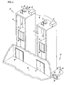
- FIG. 1 is a partially broken-away schematic view of an elevator system network, with a floor landing in a building shown having two elevator systems and a building communications system;
- FIG. 2 is an enlarged schematic view of the building communications system of FIG. 1 shown with a building monitoring center and controller transceivers;
- FIG. 3 is a schematic view of an area communications system including building monitoring centers linked to a central station via telephone line;
- FIG. 4 is a schematic view of an area communications system similar to that shown in FIG. 3 except that a wireless communication link is used between one of the building monitoring centers and the central station;
- FIG. 5 is a schematic view of two adjacently located area communications systems linked together via their building monitoring centers.
- an elevator system network 10 includes a plurality of elevator cars 12 , each of which is supported in a hoistway 14 .
- Each elevator car 12 is attached to a respective rope 16 with a motor 18 driving each rope 16 to move each elevator car 12 independently between floor landings 20 of the building.
- Each motor 18 receives electronic direction and speed commands from a controller 22 dedicated to each elevator.
- Each elevator hoistway 14 has a hoistway doorway opening 24 at the floor landing 20 for the ingress and egress of passengers.
- the elevator cars 12 have car doorways 26 that cooperate with the hoistway doorway openings 24 .
- the elevator system network 10 also includes a building communications network 27 for wireless communications and monitoring of elevators therein, as can also be seen in FIG. 2 .
- the building communications network 27 includes a controller transceiver 28 connected to a controller transceiver antenna 29 which is hard wired to one of the controllers 22 in the elevator system network 10 .
- Each of the controllers 22 in the building is connected to the controller transceiver 28 via a suitable hard wire, as indicated by the letter W.
- the building communications network 27 also includes a building transceiver 30 with a building transceiver antenna 32 .
- the building transceiver 30 is connected via telephone line 33 to a monitoring center 36 with a display screen 38 .
- an area communications system 50 includes a central station 52 , which communicates with the building transceivers 30 .
- the central station 52 is hard wired to a central station transceiver 53 having an omni-directional station transceiver antenna 54 .
- the hard wiring between the central station 52 and central station transceiver 53 is telephone line.
- the transceiver antenna 54 communicates with the building transceiver antennas 32 located in the network 50 .
- a central station display screen 56 displays elevator operating data of any elevator in the area communications network 50 .
- an area communication system 60 includes a central station 52 which communicates which is linked via telephone line 61 to building transceiver 62 A.
- Building transceivers 62 A, 62 B and 62 C are in wireless communication with each other using transceiver antennas 32 , and any of the building transceivers is reachable from the central station 52 via the telephone line 61 connected between the building transceiver 62 A and the central station 52 .
- a wide area communication network 70 includes at least two adjacently located area communication systems 60 .
- the building transceivers 62 have been labeled with the letters A through F, with building transceivers 62 A, 62 B and 62 C belonging to one area communication system 60 , and building transceivers 62 D, 62 E and 62 F belonging to the adjacent area communication system 60 .
- Each of the two area communication systems 60 have their own central station 52 which is hard-wired to building transceivers 62 A and 62 F, respectively.
- Building transceivers 62 C and 62 D are located within operable wireless transmission range of one another, as indicated by arrow 71 , so that in the event that one of the central stations 52 fails or is inoperable for some reason, the building transceivers of the effected area communication system 60 can be reached via the central station 52 of the adjacent communication system 60 .
- a hand-held control unit 72 can communicate with any controller transceiver 28 if the control unit 72 is within its operable communication range of the transceiver 28 .
- the building communications network 27 is used in a building having one or more elevator systems, with each elevator system having a dedicated controller, as best seen in FIG. 1 .
- the controllers 22 are hard-wired together, and one of the controllers is equipped with a transceiver 28 with a unique electronic address.
- FIG. 1 presumes that the elevators are situated such that a hard wire connection between the elevators is possible.
- each elevator can be configured with its own controller transceiver 28 and antenna 29 so that the building transceiver 30 can communicate with each elevator controller 22 .
- the building monitoring center 36 is programmed with the electronic address of the transceiver 28 and is capable of communicating with any of the elevators in the network via the single transceiver 28 . In this manner, a maintenance or emergency worker can contact or monitor any specific elevator by entering the electronic address for the specific controller. After entering an electronic address, emergency or maintenance personnel view the display screen 38 to monitor or change operating data of any of the elevators or communicate verbally with elevator occupants.
- the building monitoring center 36 is located in the building so as to provide emergency or maintenance personnel with a safe, convenient location to control, monitor or communicate with each elevator in the elevator system network 10 .
- the area communications network 50 is formed with multiple building communication networks 27 located within an operable transceiving range of the central station 52 , as best seen in FIG. 3 .
- the operable transceiving range is a function of the type of transceiver used in the building communications networks 27 .
- the central station 52 is programmed with the electronic addresses of all transceivers 28 in the network 27 so that personnel can use the display screen 56 to enter the appropriate electronic address and interact, via the building transceivers 30 , with a specific controller 22 , or verbally communicate with a person in any of the elevator cars.
- the wireless communications are transmitted from the central station 52 to the building transceiver 30 , and finally to a specific controller 22 via its associated controller transceiver 28 .
- the area communications network 60 is similar to the area communications network 50 , except that the central station 52 is hard wired to one of the building transceivers 30 instead of using a wireless link.
- the remaining building transceivers 30 have wireless transceivers and communicate with the central station 52 via the building transceiver 30 with the hard wire link to the central station 52 .
- the hand held unit 72 is used by maintenance or emergency personnel to interact with any elevator controller 22 as long as the unit 72 is within its operable transceiving range. As long as the electronic address of an elevator is known, a communication link can be established with that elevator via its elevator controller 22 .
- One advantage of the present invention is the reduction or elimination of hard wiring or telephone lines to communicate between a control center and multiple elevators in a building.
- Remote antennas attached to controllers and monitoring centers allow two-way wireless communications between the elevator controllers and building-monitoring center.
- Another advantage of the present invention is that costly phone line service is not required to link elevator systems of separate buildings.
- the elevator systems are remotely linked together by antenna, and a single telephone line linking a control station to one elevator provides communications between the control station and any elevator in the network.
- transceiver that can be used as a controller transceiver 28 , a building transceiver 30 , or a central station transceiver 53 is model WIT 2400 manufactured by Digital Wireless Communications, of Norcross, Ga.
- This model transmits data in a 2.4 GHz frequency band, which is a known to be a noisy band because it is also used by microwave ovens.
- the WIT 2400 avoids the noise problem by utilizing a proprietary form of direct sequence spread spectrum technology, which transmits data between the transceivers in a random, rapidly changing sequence of frequencies. This technology ensures a robust communication link between transceivers that avoids interference or jamming.
- the 2.4 GHz frequency band also provides a secure, high bandwidth range to transmit data for distances up to one thousand meters (1000 m). This frequency band is unregulated in most countries across the globe, thus allowing for a nearly universal solution to wireless elevator communications.
- the preferred embodiment uses a WIT 2400 transceiver and operates in the 2.4 GHz frequency band
- other types of transceivers can be used and can operate at other frequency bands.
- the present invention is described in connection with an electrically-driven elevator, the system is equally applicable to one that is driven hydraulically.
- the local monitoring center functions as described whether the building has one or multiple elevators because each elevator is programmed with a unique electronic address.
- the controller transceiver antenna may be positioned and mounted remotely from its associated transceiver to provide a clear path for communications between the building transceiver antenna and the controller transceiver antenna.
- suitable wire can be routed to connect these components.
- hard wire connections such as phone line or suitable wire can be avoided altogether by using RF transmitters to communicate between the components.
Abstract
A wireless communications system for use with an elevator system in a building includes a first transceiver connected to an elevator controller and a second transceiver located remotely within the building. The first and second transceivers each have antennas which allow wireless transmission of data between the transceivers. A building monitoring center is hard-wired to the second transceiver to allow personnel to monitor and interact with each elevator controller. A third transceiver and antenna are located outside of the building and are connected to a central monitoring station to allow remote monitoring and interaction with each elevator controller. The wireless communications system can be used with a network of elevators where each elevator has a unique electronic address to allow discreet wireless communications with a specific elevator.
Description
1. Technical Field
The present invention relates to an elevator system and, more particularly, to a wireless elevator communications system for transmitting voices and operating data between an elevator and a monitoring center.
2. Background Art
The practice of hard wiring together multiple elevator systems to form a communications system is known in the art. In buildings with multiple elevators, each elevator transmits its performance and operating data through hard wiring to a local monitoring center, which then compiles the data for on-site review or subsequent transmission to a central station capable of monitoring elevators of several buildings. Public phone lines are typically used to connect the local monitoring center with the central monitoring station.
The current state of the art creates a communications system by hard wiring together a network of elevator systems, which can be impractical or impossible in some applications. In a building with multiple elevators, hard wiring the elevators to a local monitoring center is a difficult, cumbersome and expensive task which involves routing communication cables and wiring around or through obstacles such as floors and walls. When voice and data communications are transmitted between the monitoring center and the control station using public phone lines substantial use and maintenance expenses are incurred.
There is a need for an elevator communications system that does not require expensive hard wiring in each building or the high cost associated with the extensive use and maintenance of public phone lines in a network of multiple elevator systems in separate buildings.
It is an object of the present invention to provide a voice and data communications system that is easier and cheaper to install and use by eliminating the need for hard wiring between elevators in separate buildings.
It is another object of the present invention to provide a common monitoring station to simplify the monitoring, collecting, or changing of operating data for an array of elevators.
According to the present invention, a wireless communications system for use in a building with at least one electronically controlled elevator system includes a first transceiver attached to an electronic elevator controller and a second transceiver attached to a local monitoring center located in the building. The first transceiver has a first antenna which transmits data to and from a second antenna attached to the second transceiver. The communications system of the present invention may also include a second monitoring center having a third transceiver which communicates with the second transceiver to enable monitoring of the elevator from outside of the building. The first transceiver has a unique electronic address allowing discreet communications between the elevator and monitoring center in a communication system with multiple elevators.
According to one embodiment of the present invention, a mobile transceiver can be used with the communications network to allow emergency personnel to communicate from a safe location with any of the elevators within the functional range of the mobile transceiver.
According to another embodiment of the present invention, transceivers of neighboring communications systems are used to link the systems in the event that a monitoring center fails.
One advantage of the present invention is that hard wiring is no longer required to link multiple elevators in a single building. Operating data is transmitted between the elevators and a monitoring center using wireless transceivers.
Another advantage of the present invention is that hard wiring is no longer required to link elevator systems in separate buildings. The elevators are networked together using remote transceivers, thereby eliminating use of some phone lines, reducing monthly phone line expenses, and simplifying the installation of the entire network.
These and other objects, features and advantages of the present invention will become more apparent in the light of the following detailed description of best mode embodiments thereof as illustrated in the accompanying drawings.
FIG. 1 is a partially broken-away schematic view of an elevator system network, with a floor landing in a building shown having two elevator systems and a building communications system;
FIG. 2 is an enlarged schematic view of the building communications system of FIG. 1 shown with a building monitoring center and controller transceivers;
FIG. 3 is a schematic view of an area communications system including building monitoring centers linked to a central station via telephone line;
FIG. 4 is a schematic view of an area communications system similar to that shown in FIG. 3 except that a wireless communication link is used between one of the building monitoring centers and the central station; and
FIG. 5 is a schematic view of two adjacently located area communications systems linked together via their building monitoring centers.
Referring to FIG. 1, an elevator system network 10 includes a plurality of elevator cars 12, each of which is supported in a hoistway 14. Each elevator car 12 is attached to a respective rope 16 with a motor 18 driving each rope 16 to move each elevator car 12 independently between floor landings 20 of the building. Each motor 18 receives electronic direction and speed commands from a controller 22 dedicated to each elevator. Each elevator hoistway 14 has a hoistway doorway opening 24 at the floor landing 20 for the ingress and egress of passengers. The elevator cars 12 have car doorways 26 that cooperate with the hoistway doorway openings 24.
The elevator system network 10 also includes a building communications network 27 for wireless communications and monitoring of elevators therein, as can also be seen in FIG. 2. The building communications network 27 includes a controller transceiver 28 connected to a controller transceiver antenna 29 which is hard wired to one of the controllers 22 in the elevator system network 10. Each of the controllers 22 in the building is connected to the controller transceiver 28 via a suitable hard wire, as indicated by the letter W.
The building communications network 27 also includes a building transceiver 30 with a building transceiver antenna 32. The building transceiver 30 is connected via telephone line 33 to a monitoring center 36 with a display screen 38.
Referring to FIG. 3, an area communications system 50 includes a central station 52, which communicates with the building transceivers 30. The central station 52 is hard wired to a central station transceiver 53 having an omni-directional station transceiver antenna 54. Preferably, the hard wiring between the central station 52 and central station transceiver 53 is telephone line. The transceiver antenna 54 communicates with the building transceiver antennas 32 located in the network 50. A central station display screen 56 displays elevator operating data of any elevator in the area communications network 50.
Referring to FIG. 4, an area communication system 60 includes a central station 52 which communicates which is linked via telephone line 61 to building transceiver 62A. Building transceivers 62A, 62B and 62C are in wireless communication with each other using transceiver antennas 32, and any of the building transceivers is reachable from the central station 52 via the telephone line 61connected between the building transceiver 62A and the central station 52.
Referring to FIG. 5, a wide area communication network 70 includes at least two adjacently located area communication systems 60. For illustrative purposes, the building transceivers 62 have been labeled with the letters A through F, with building transceivers 62A, 62B and 62C belonging to one area communication system 60, and building transceivers 62D, 62E and 62F belonging to the adjacent area communication system 60.
Each of the two area communication systems 60 have their own central station 52 which is hard-wired to building transceivers 62A and 62F, respectively. Building transceivers 62C and 62D are located within operable wireless transmission range of one another, as indicated by arrow 71, so that in the event that one of the central stations 52 fails or is inoperable for some reason, the building transceivers of the effected area communication system 60 can be reached via the central station 52 of the adjacent communication system 60.
A hand-held control unit 72 can communicate with any controller transceiver 28 if the control unit 72 is within its operable communication range of the transceiver 28.
In operation, the building communications network 27 is used in a building having one or more elevator systems, with each elevator system having a dedicated controller, as best seen in FIG. 1. The controllers 22 are hard-wired together, and one of the controllers is equipped with a transceiver 28 with a unique electronic address. However, the embodiment of FIG. 1 presumes that the elevators are situated such that a hard wire connection between the elevators is possible. In the alternative, each elevator can be configured with its own controller transceiver 28 and antenna 29 so that the building transceiver 30 can communicate with each elevator controller 22.
The building monitoring center 36 is programmed with the electronic address of the transceiver 28 and is capable of communicating with any of the elevators in the network via the single transceiver 28. In this manner, a maintenance or emergency worker can contact or monitor any specific elevator by entering the electronic address for the specific controller. After entering an electronic address, emergency or maintenance personnel view the display screen 38 to monitor or change operating data of any of the elevators or communicate verbally with elevator occupants. Thus, the building monitoring center 36 is located in the building so as to provide emergency or maintenance personnel with a safe, convenient location to control, monitor or communicate with each elevator in the elevator system network 10.
The area communications network 50 is formed with multiple building communication networks 27 located within an operable transceiving range of the central station 52, as best seen in FIG. 3. The operable transceiving range is a function of the type of transceiver used in the building communications networks 27. The central station 52 is programmed with the electronic addresses of all transceivers 28 in the network 27 so that personnel can use the display screen 56 to enter the appropriate electronic address and interact, via the building transceivers 30, with a specific controller 22, or verbally communicate with a person in any of the elevator cars. The wireless communications are transmitted from the central station 52 to the building transceiver 30, and finally to a specific controller 22 via its associated controller transceiver 28.
The area communications network 60 is similar to the area communications network 50, except that the central station 52 is hard wired to one of the building transceivers 30 instead of using a wireless link. The remaining building transceivers 30 have wireless transceivers and communicate with the central station 52 via the building transceiver 30 with the hard wire link to the central station 52.
The hand held unit 72 is used by maintenance or emergency personnel to interact with any elevator controller 22 as long as the unit 72 is within its operable transceiving range. As long as the electronic address of an elevator is known, a communication link can be established with that elevator via its elevator controller 22.
One advantage of the present invention is the reduction or elimination of hard wiring or telephone lines to communicate between a control center and multiple elevators in a building. Remote antennas attached to controllers and monitoring centers allow two-way wireless communications between the elevator controllers and building-monitoring center.
Another advantage of the present invention is that costly phone line service is not required to link elevator systems of separate buildings. The elevator systems are remotely linked together by antenna, and a single telephone line linking a control station to one elevator provides communications between the control station and any elevator in the network.
One type of transceiver that can be used as a controller transceiver 28, a building transceiver 30, or a central station transceiver 53 is model WIT 2400 manufactured by Digital Wireless Communications, of Norcross, Ga. This model transmits data in a 2.4 GHz frequency band, which is a known to be a noisy band because it is also used by microwave ovens. The WIT 2400 avoids the noise problem by utilizing a proprietary form of direct sequence spread spectrum technology, which transmits data between the transceivers in a random, rapidly changing sequence of frequencies. This technology ensures a robust communication link between transceivers that avoids interference or jamming. The 2.4 GHz frequency band also provides a secure, high bandwidth range to transmit data for distances up to one thousand meters (1000 m). This frequency band is unregulated in most countries across the globe, thus allowing for a nearly universal solution to wireless elevator communications.
Although the preferred embodiment uses a WIT 2400 transceiver and operates in the 2.4 GHz frequency band, other types of transceivers can be used and can operate at other frequency bands.
While preferred embodiments have been shown and described above, various modifications and substitutions may be made without departing from the spirit and scope of the invention. For example, while the present invention is described in connection with an electrically-driven elevator, the system is equally applicable to one that is driven hydraulically. Further, the local monitoring center functions as described whether the building has one or multiple elevators because each elevator is programmed with a unique electronic address. Additionally, within an area densely populated with area communication networks, it may be beneficial to use directionally sensitive building transceiver antennas to narrowly focus communications from the building communications network to the central station. Still further, the controller transceiver antenna may be positioned and mounted remotely from its associated transceiver to provide a clear path for communications between the building transceiver antenna and the controller transceiver antenna. Still even further, in lieu of a suitable telephone line to connect the central station to the central station transceiver, or to connect the building transceiver to the monitoring center, suitable wire can be routed to connect these components. In the alternative, hard wire connections such as phone line or suitable wire can be avoided altogether by using RF transmitters to communicate between the components. Accordingly, it is to be understood that the present invention has been described by way of example and not by way of limitation.
Claims (7)
1. An elevator monitoring system for monitoring the performance of elevators located within multiple buildings comprising:
a first elevator located within a first building, said elevator in communication with a first building transceiver for receiving elevator performance data from said first elevator;
a second elevator located within a second building, said second elevator in communication with a second building transceiver for receiving elevator performance data from said second elevator;
a third elevator located within a third building, said third elevator in communication with a third building transceiver for receiving elevator performance data from said third elevator, and wherein said building transceivers are in wireless communication with at least one of the other building transceivers for transmitting and receiving elevator performance data; and
a first central monitoring station in communication with said first building transceiver for receiving elevator performance data from said first, second and third elevators.
2. The elevator monitoring system of claim 1 wherein the first central monitoring station is in communication with said first and second building transceivers for receiving elevator performance data from said first, second and third elevators, wherein said first central monitoring station receives said performance data from said first, second, and third elevators in the event that communication between said first central monitoring station and one of said first and second transceivers is interrupted.
3. The elevator monitoring system of claim 1 wherein communication between said first elevator and said first transceiver is wireless.
4. The elevator monitoring system of claim 1 wherein communication between said first central monitoring station and said first building transceiver is wireless.
5. The elevator monitoring system of any one of claims 3 or 4 wherein the performance data is transmitted using frequency hopping spread spectrum technique.
6. The elevator monitoring system of claim 1 wherein communication between said first central monitoring station and said first building is through a phone line.
7. The elevator monitoring system of claim 1 further comprising a second central monitoring station in communication with said second building transceiver for receiving elevator performance data from said first, second and third elevators.
Priority Applications (4)
| Application Number | Priority Date | Filing Date | Title |
|---|---|---|---|
| US09/484,506 US6684055B1 (en) | 2000-01-18 | 2000-01-18 | System for remotely communicating voice and data to and from an elevator controller |
| PCT/US2001/001985 WO2001053183A1 (en) | 2000-01-18 | 2001-01-17 | A system for remotely communicating voice and data to and from an elevator controller |
| DE60133158T DE60133158T2 (en) | 2000-01-18 | 2001-01-17 | SYSTEM FOR REMOTE TRANSMISSION OF VOICES AND DATA TO AND FROM AN ELEVATOR CONTROL |
| EP01903187A EP1163182B1 (en) | 2000-01-18 | 2001-01-17 | A system for remotely communicating voice and data to and from an elevator controller |
Applications Claiming Priority (1)
| Application Number | Priority Date | Filing Date | Title |
|---|---|---|---|
| US09/484,506 US6684055B1 (en) | 2000-01-18 | 2000-01-18 | System for remotely communicating voice and data to and from an elevator controller |
Publications (1)
| Publication Number | Publication Date |
|---|---|
| US6684055B1 true US6684055B1 (en) | 2004-01-27 |
Family
ID=23924425
Family Applications (1)
| Application Number | Title | Priority Date | Filing Date |
|---|---|---|---|
| US09/484,506 Expired - Fee Related US6684055B1 (en) | 2000-01-18 | 2000-01-18 | System for remotely communicating voice and data to and from an elevator controller |
Country Status (4)
| Country | Link |
|---|---|
| US (1) | US6684055B1 (en) |
| EP (1) | EP1163182B1 (en) |
| DE (1) | DE60133158T2 (en) |
| WO (1) | WO2001053183A1 (en) |
Cited By (20)
| Publication number | Priority date | Publication date | Assignee | Title |
|---|---|---|---|---|
| US20040192285A1 (en) * | 2003-03-28 | 2004-09-30 | Sony Corporation/Sony Electronics, Inc. | Apparatus and method for communicating a wireless data signal in a building |
| US7699142B1 (en) | 2006-05-12 | 2010-04-20 | Wurtec Elevator Products & Services | Diagnostic system having user defined sequence logic map for a transportation device |
| US20110200023A1 (en) * | 2010-02-17 | 2011-08-18 | Dave Murray | Method and system for determining a position fix indoors |
| US20110237185A1 (en) * | 2010-03-26 | 2011-09-29 | Dave Murray | Method and system for determining a location for a rf communication device based on its proximity to a mobile device |
| CN102756959A (en) * | 2011-04-28 | 2012-10-31 | 上海韦铫机电设备有限公司 | One-connected-more elevator intelligent instrumented terminal and communication method thereof |
| CN103384352A (en) * | 2013-07-30 | 2013-11-06 | 深圳市汇川技术股份有限公司 | Elevator remote talkback system and access device |
| US8583111B2 (en) | 2001-10-10 | 2013-11-12 | Peregrine Semiconductor Corporation | Switch circuit and method of switching radio frequency signals |
| GB2514355A (en) * | 2013-05-20 | 2014-11-26 | Ace Lifts Ltd | Monitoring elevator systems |
| US20150056905A1 (en) * | 2012-03-16 | 2015-02-26 | Cij Co., Ltd. | Oxygen supply elevator |
| US20160107861A1 (en) * | 2013-06-11 | 2016-04-21 | Otis Elevator Company | Cloud server based control |
| US9419565B2 (en) | 2013-03-14 | 2016-08-16 | Peregrine Semiconductor Corporation | Hot carrier injection compensation |
| US9852861B2 (en) | 2015-09-12 | 2017-12-26 | Balmore Black | Addressable electric safety contact monitoring system |
| CN109328438A (en) * | 2016-06-14 | 2019-02-12 | 通力股份公司 | The elevator wireless electric signal of enhancing covers |
| US10622990B2 (en) | 2005-07-11 | 2020-04-14 | Psemi Corporation | Method and apparatus for use in improving linearity of MOSFETs using an accumulated charge sink |
| US10790390B2 (en) | 2005-07-11 | 2020-09-29 | Psemi Corporation | Method and apparatus for use in improving linearity of MOSFETs using an accumulated charge sink-harmonic wrinkle reduction |
| US10804892B2 (en) | 2005-07-11 | 2020-10-13 | Psemi Corporation | Circuit and method for controlling charge injection in radio frequency switches |
| US10818796B2 (en) | 2005-07-11 | 2020-10-27 | Psemi Corporation | Method and apparatus improving gate oxide reliability by controlling accumulated charge |
| US10865069B2 (en) * | 2018-09-18 | 2020-12-15 | Otis Elevator Company | Effecting communication bridge with elevator system |
| EP3609205B1 (en) | 2018-08-10 | 2021-12-15 | Otis Elevator Company | Wireless data communication in a system |
| USRE48965E1 (en) | 2005-07-11 | 2022-03-08 | Psemi Corporation | Method and apparatus improving gate oxide reliability by controlling accumulated charge |
Families Citing this family (1)
| Publication number | Priority date | Publication date | Assignee | Title |
|---|---|---|---|---|
| CN111039110B (en) * | 2019-12-19 | 2021-11-23 | 北京易云达科技有限公司 | Intelligent voice elevator taking system |
Citations (22)
| Publication number | Priority date | Publication date | Assignee | Title |
|---|---|---|---|---|
| US4568909A (en) | 1983-12-19 | 1986-02-04 | United Technologies Corporation | Remote elevator monitoring system |
| US4622538A (en) * | 1984-07-18 | 1986-11-11 | Otis Elevator Company | Remote monitoring system state machine and method |
| US4941207A (en) * | 1984-05-01 | 1990-07-10 | Nihon Musen Kabushiki Kaisha | Structure for wireless communication in an electromagnetically shielded building |
| US4979593A (en) * | 1987-08-26 | 1990-12-25 | Mitsubishi Denki Kabushiki Kaisha | Elevator controller |
| US5282239A (en) * | 1991-07-09 | 1994-01-25 | Mitsubishi Denki Kabushiki Kaisha | Cordless telephone system for moving conveyances |
| US5291193A (en) * | 1988-01-21 | 1994-03-01 | Matsushita Electric Works, Ltd. | Identification registration for a wireless transmission-reception control system |
| US5349631A (en) * | 1991-11-21 | 1994-09-20 | Airtouch Communications | Inbuilding telephone communication system |
| US5463673A (en) * | 1993-04-29 | 1995-10-31 | Northern Telecom Limited | In-building radio deployment technique for wireless personal communications systems |
| US5603080A (en) * | 1992-11-23 | 1997-02-11 | Telefonaktiebolaget Lm Ericsson | Radio coverage in closed environments |
| US5668562A (en) * | 1996-04-19 | 1997-09-16 | Lgc Wireless, Inc. | Measurement-based method of optimizing the placement of antennas in a RF distribution system |
| US5673307A (en) * | 1994-02-17 | 1997-09-30 | Spectralink Corporation | Handoff method for indoor cellular phone system |
| JPH09297895A (en) | 1996-05-08 | 1997-11-18 | Hitachi Building Syst Co Ltd | Remote monitor system for building facility and equipment |
| US5817994A (en) | 1995-07-31 | 1998-10-06 | Otis Elevator Company | Remote fail-safe control for elevator |
| US5889239A (en) * | 1996-11-04 | 1999-03-30 | Otis Elevator Company | Method for monitoring elevator leveling performance with improved accuracy |
| WO1999043587A1 (en) | 1998-02-24 | 1999-09-02 | Teclion | A method and a device for monitoring the operation of an elevator |
| US6032035A (en) * | 1997-05-21 | 2000-02-29 | Elcombe Systems Limited | Emergency response system |
| US6108535A (en) * | 1994-06-20 | 2000-08-22 | Kabushiki Kaisha Toshiba | Mobile communication system including service management of traffic machines |
| US6265964B1 (en) * | 1999-03-24 | 2001-07-24 | Brian Payne | Automated building activation system |
| US6288688B1 (en) * | 1998-06-25 | 2001-09-11 | Elevating Communications, Inc. | System for distribution and display of advertisements within elevator cars |
| US6356204B1 (en) * | 1997-08-19 | 2002-03-12 | Tectonics Research Group, Inc. | Method and apparatus for detecting impending earthquakes |
| US6437692B1 (en) * | 1998-06-22 | 2002-08-20 | Statsignal Systems, Inc. | System and method for monitoring and controlling remote devices |
| US6498789B1 (en) * | 1997-12-15 | 2002-12-24 | Matsushita Electric Industrial Co., Ltd. | CDMA mobile communications device |
-
2000
- 2000-01-18 US US09/484,506 patent/US6684055B1/en not_active Expired - Fee Related
-
2001
- 2001-01-17 EP EP01903187A patent/EP1163182B1/en not_active Expired - Lifetime
- 2001-01-17 WO PCT/US2001/001985 patent/WO2001053183A1/en active Application Filing
- 2001-01-17 DE DE60133158T patent/DE60133158T2/en not_active Expired - Lifetime
Patent Citations (22)
| Publication number | Priority date | Publication date | Assignee | Title |
|---|---|---|---|---|
| US4568909A (en) | 1983-12-19 | 1986-02-04 | United Technologies Corporation | Remote elevator monitoring system |
| US4941207A (en) * | 1984-05-01 | 1990-07-10 | Nihon Musen Kabushiki Kaisha | Structure for wireless communication in an electromagnetically shielded building |
| US4622538A (en) * | 1984-07-18 | 1986-11-11 | Otis Elevator Company | Remote monitoring system state machine and method |
| US4979593A (en) * | 1987-08-26 | 1990-12-25 | Mitsubishi Denki Kabushiki Kaisha | Elevator controller |
| US5291193A (en) * | 1988-01-21 | 1994-03-01 | Matsushita Electric Works, Ltd. | Identification registration for a wireless transmission-reception control system |
| US5282239A (en) * | 1991-07-09 | 1994-01-25 | Mitsubishi Denki Kabushiki Kaisha | Cordless telephone system for moving conveyances |
| US5349631A (en) * | 1991-11-21 | 1994-09-20 | Airtouch Communications | Inbuilding telephone communication system |
| US5603080A (en) * | 1992-11-23 | 1997-02-11 | Telefonaktiebolaget Lm Ericsson | Radio coverage in closed environments |
| US5463673A (en) * | 1993-04-29 | 1995-10-31 | Northern Telecom Limited | In-building radio deployment technique for wireless personal communications systems |
| US5673307A (en) * | 1994-02-17 | 1997-09-30 | Spectralink Corporation | Handoff method for indoor cellular phone system |
| US6108535A (en) * | 1994-06-20 | 2000-08-22 | Kabushiki Kaisha Toshiba | Mobile communication system including service management of traffic machines |
| US5817994A (en) | 1995-07-31 | 1998-10-06 | Otis Elevator Company | Remote fail-safe control for elevator |
| US5668562A (en) * | 1996-04-19 | 1997-09-16 | Lgc Wireless, Inc. | Measurement-based method of optimizing the placement of antennas in a RF distribution system |
| JPH09297895A (en) | 1996-05-08 | 1997-11-18 | Hitachi Building Syst Co Ltd | Remote monitor system for building facility and equipment |
| US5889239A (en) * | 1996-11-04 | 1999-03-30 | Otis Elevator Company | Method for monitoring elevator leveling performance with improved accuracy |
| US6032035A (en) * | 1997-05-21 | 2000-02-29 | Elcombe Systems Limited | Emergency response system |
| US6356204B1 (en) * | 1997-08-19 | 2002-03-12 | Tectonics Research Group, Inc. | Method and apparatus for detecting impending earthquakes |
| US6498789B1 (en) * | 1997-12-15 | 2002-12-24 | Matsushita Electric Industrial Co., Ltd. | CDMA mobile communications device |
| WO1999043587A1 (en) | 1998-02-24 | 1999-09-02 | Teclion | A method and a device for monitoring the operation of an elevator |
| US6437692B1 (en) * | 1998-06-22 | 2002-08-20 | Statsignal Systems, Inc. | System and method for monitoring and controlling remote devices |
| US6288688B1 (en) * | 1998-06-25 | 2001-09-11 | Elevating Communications, Inc. | System for distribution and display of advertisements within elevator cars |
| US6265964B1 (en) * | 1999-03-24 | 2001-07-24 | Brian Payne | Automated building activation system |
Cited By (34)
| Publication number | Priority date | Publication date | Assignee | Title |
|---|---|---|---|---|
| US8583111B2 (en) | 2001-10-10 | 2013-11-12 | Peregrine Semiconductor Corporation | Switch circuit and method of switching radio frequency signals |
| US10812068B2 (en) | 2001-10-10 | 2020-10-20 | Psemi Corporation | Switch circuit and method of switching radio frequency signals |
| US10797694B2 (en) | 2001-10-10 | 2020-10-06 | Psemi Corporation | Switch circuit and method of switching radio frequency signals |
| US9225378B2 (en) | 2001-10-10 | 2015-12-29 | Peregrine Semiconductor Corpopration | Switch circuit and method of switching radio frequency signals |
| US7065350B2 (en) * | 2003-03-28 | 2006-06-20 | Sony Corporation | Apparatus and method for communicating a wireless data signal in a building |
| US20040192285A1 (en) * | 2003-03-28 | 2004-09-30 | Sony Corporation/Sony Electronics, Inc. | Apparatus and method for communicating a wireless data signal in a building |
| US10797172B2 (en) | 2005-07-11 | 2020-10-06 | Psemi Corporation | Method and apparatus for use in improving linearity of MOSFETs using an accumulated charge sink-harmonic wrinkle reduction |
| US10804892B2 (en) | 2005-07-11 | 2020-10-13 | Psemi Corporation | Circuit and method for controlling charge injection in radio frequency switches |
| USRE48965E1 (en) | 2005-07-11 | 2022-03-08 | Psemi Corporation | Method and apparatus improving gate oxide reliability by controlling accumulated charge |
| USRE48944E1 (en) | 2005-07-11 | 2022-02-22 | Psemi Corporation | Method and apparatus for use in improving linearity of MOSFETS using an accumulated charge sink |
| US10818796B2 (en) | 2005-07-11 | 2020-10-27 | Psemi Corporation | Method and apparatus improving gate oxide reliability by controlling accumulated charge |
| US10797691B1 (en) | 2005-07-11 | 2020-10-06 | Psemi Corporation | Method and apparatus for use in improving linearity of MOSFETs using an accumulated charge sink |
| US10790390B2 (en) | 2005-07-11 | 2020-09-29 | Psemi Corporation | Method and apparatus for use in improving linearity of MOSFETs using an accumulated charge sink-harmonic wrinkle reduction |
| US10680600B2 (en) | 2005-07-11 | 2020-06-09 | Psemi Corporation | Method and apparatus for use in improving linearity of MOSFETs using an accumulated charge sink |
| US10622990B2 (en) | 2005-07-11 | 2020-04-14 | Psemi Corporation | Method and apparatus for use in improving linearity of MOSFETs using an accumulated charge sink |
| US7699142B1 (en) | 2006-05-12 | 2010-04-20 | Wurtec Elevator Products & Services | Diagnostic system having user defined sequence logic map for a transportation device |
| US8818270B2 (en) | 2010-02-12 | 2014-08-26 | Broadcom Corporation | Method and system for determining a location for a RF communication device based on its proximity to a mobile device |
| US20110200023A1 (en) * | 2010-02-17 | 2011-08-18 | Dave Murray | Method and system for determining a position fix indoors |
| US8831507B2 (en) * | 2010-02-17 | 2014-09-09 | Broadcom Corporation | Method and system for determining a position fix indoors |
| US8532571B2 (en) | 2010-03-26 | 2013-09-10 | Broadcom Corporation | Method and system for determining a location for a RF communication device based on its proximity to a mobile device |
| US20110237185A1 (en) * | 2010-03-26 | 2011-09-29 | Dave Murray | Method and system for determining a location for a rf communication device based on its proximity to a mobile device |
| CN102756959A (en) * | 2011-04-28 | 2012-10-31 | 上海韦铫机电设备有限公司 | One-connected-more elevator intelligent instrumented terminal and communication method thereof |
| US20150056905A1 (en) * | 2012-03-16 | 2015-02-26 | Cij Co., Ltd. | Oxygen supply elevator |
| US9419565B2 (en) | 2013-03-14 | 2016-08-16 | Peregrine Semiconductor Corporation | Hot carrier injection compensation |
| GB2514355A (en) * | 2013-05-20 | 2014-11-26 | Ace Lifts Ltd | Monitoring elevator systems |
| US20160107861A1 (en) * | 2013-06-11 | 2016-04-21 | Otis Elevator Company | Cloud server based control |
| CN103384352A (en) * | 2013-07-30 | 2013-11-06 | 深圳市汇川技术股份有限公司 | Elevator remote talkback system and access device |
| CN103384352B (en) * | 2013-07-30 | 2016-06-22 | 深圳市汇川技术股份有限公司 | Elevator remote talkback system and access device |
| US9852861B2 (en) | 2015-09-12 | 2017-12-26 | Balmore Black | Addressable electric safety contact monitoring system |
| CN109328438A (en) * | 2016-06-14 | 2019-02-12 | 通力股份公司 | The elevator wireless electric signal of enhancing covers |
| CN109328438B (en) * | 2016-06-14 | 2022-03-04 | 通力股份公司 | Enhanced elevator radio signal coverage |
| US11431372B2 (en) * | 2016-06-14 | 2022-08-30 | Kone Corporation | Enhanced elevator radio signal coverage |
| EP3609205B1 (en) | 2018-08-10 | 2021-12-15 | Otis Elevator Company | Wireless data communication in a system |
| US10865069B2 (en) * | 2018-09-18 | 2020-12-15 | Otis Elevator Company | Effecting communication bridge with elevator system |
Also Published As
| Publication number | Publication date |
|---|---|
| WO2001053183A1 (en) | 2001-07-26 |
| WO2001053183A9 (en) | 2002-10-31 |
| DE60133158D1 (en) | 2008-04-24 |
| EP1163182B1 (en) | 2008-03-12 |
| DE60133158T2 (en) | 2009-03-19 |
| EP1163182A1 (en) | 2001-12-19 |
Similar Documents
| Publication | Publication Date | Title |
|---|---|---|
| US6684055B1 (en) | System for remotely communicating voice and data to and from an elevator controller | |
| KR100904806B1 (en) | Two-part wireless communications system for elevator hallway fixtures | |
| KR100769314B1 (en) | Elevator system | |
| EP2166679B1 (en) | Wireless communication system and lift system having the same | |
| CN1697772B (en) | Elevator wireless communication infrastructure using piconet modules | |
| US11250690B2 (en) | Security system for buildings with elevator installations | |
| WO2017216413A1 (en) | Enhanced elevator radio signal coverage | |
| KR20170112031A (en) | Elevator management system using by visible light communication | |
| CN210505117U (en) | Relay-mode elevator car wireless communication system | |
| JPH08316720A (en) | Radio equipment for elevator | |
| WO2000034169A1 (en) | Wireless elevator hall fixtures | |
| KR100806825B1 (en) | Wireless communication system and lift system having the same | |
| EP3569542B1 (en) | Wireless communication in an elevator system | |
| JP3816713B2 (en) | Passenger conveyor information transmission device | |
| KR20120048213A (en) | Method for transferring wireless relay signal of zigbee protocol |
Legal Events
| Date | Code | Title | Description |
|---|---|---|---|
| AS | Assignment |
Owner name: OTIS ELEVATOR COMPANY, CONNECTICUT Free format text: ASSIGNMENT OF ASSIGNORS INTEREST;ASSIGNORS:BLACKABY, BARRY G.;REMMERS, TIMOTHY M.;REEL/FRAME:010562/0994;SIGNING DATES FROM 19991217 TO 20000118 |
|
| FEPP | Fee payment procedure |
Free format text: PAYOR NUMBER ASSIGNED (ORIGINAL EVENT CODE: ASPN); ENTITY STATUS OF PATENT OWNER: LARGE ENTITY |
|
| FPAY | Fee payment |
Year of fee payment: 4 |
|
| REMI | Maintenance fee reminder mailed | ||
| LAPS | Lapse for failure to pay maintenance fees | ||
| STCH | Information on status: patent discontinuation |
Free format text: PATENT EXPIRED DUE TO NONPAYMENT OF MAINTENANCE FEES UNDER 37 CFR 1.362 |
|
| FP | Lapsed due to failure to pay maintenance fee |
Effective date: 20120127 |