US6679864B2 - Safety shield system for prefilled syringes - Google Patents
Safety shield system for prefilled syringes Download PDFInfo
- Publication number
- US6679864B2 US6679864B2 US09/876,710 US87671001A US6679864B2 US 6679864 B2 US6679864 B2 US 6679864B2 US 87671001 A US87671001 A US 87671001A US 6679864 B2 US6679864 B2 US 6679864B2
- Authority
- US
- United States
- Prior art keywords
- shield
- barrel
- flange
- tubular
- holder
- Prior art date
- Legal status (The legal status is an assumption and is not a legal conclusion. Google has not performed a legal analysis and makes no representation as to the accuracy of the status listed.)
- Expired - Lifetime
Links
Images


Classifications
-
- A—HUMAN NECESSITIES
- A61—MEDICAL OR VETERINARY SCIENCE; HYGIENE
- A61M—DEVICES FOR INTRODUCING MEDIA INTO, OR ONTO, THE BODY; DEVICES FOR TRANSDUCING BODY MEDIA OR FOR TAKING MEDIA FROM THE BODY; DEVICES FOR PRODUCING OR ENDING SLEEP OR STUPOR
- A61M5/00—Devices for bringing media into the body in a subcutaneous, intra-vascular or intramuscular way; Accessories therefor, e.g. filling or cleaning devices, arm-rests
- A61M5/178—Syringes
- A61M5/31—Details
- A61M5/32—Needles; Details of needles pertaining to their connection with syringe or hub; Accessories for bringing the needle into, or holding the needle on, the body; Devices for protection of needles
- A61M5/3205—Apparatus for removing or disposing of used needles or syringes, e.g. containers; Means for protection against accidental injuries from used needles
- A61M5/321—Means for protection against accidental injuries by used needles
- A61M5/3243—Means for protection against accidental injuries by used needles being axially-extensible, e.g. protective sleeves coaxially slidable on the syringe barrel
- A61M5/326—Fully automatic sleeve extension, i.e. in which triggering of the sleeve does not require a deliberate action by the user
-
- A—HUMAN NECESSITIES
- A61—MEDICAL OR VETERINARY SCIENCE; HYGIENE
- A61M—DEVICES FOR INTRODUCING MEDIA INTO, OR ONTO, THE BODY; DEVICES FOR TRANSDUCING BODY MEDIA OR FOR TAKING MEDIA FROM THE BODY; DEVICES FOR PRODUCING OR ENDING SLEEP OR STUPOR
- A61M5/00—Devices for bringing media into the body in a subcutaneous, intra-vascular or intramuscular way; Accessories therefor, e.g. filling or cleaning devices, arm-rests
- A61M5/178—Syringes
- A61M5/31—Details
- A61M2005/3143—Damping means for syringe components executing relative movements, e.g. retarders or attenuators slowing down or timing syringe mechanisms
-
- A—HUMAN NECESSITIES
- A61—MEDICAL OR VETERINARY SCIENCE; HYGIENE
- A61M—DEVICES FOR INTRODUCING MEDIA INTO, OR ONTO, THE BODY; DEVICES FOR TRANSDUCING BODY MEDIA OR FOR TAKING MEDIA FROM THE BODY; DEVICES FOR PRODUCING OR ENDING SLEEP OR STUPOR
- A61M5/00—Devices for bringing media into the body in a subcutaneous, intra-vascular or intramuscular way; Accessories therefor, e.g. filling or cleaning devices, arm-rests
- A61M5/178—Syringes
- A61M5/31—Details
- A61M5/32—Needles; Details of needles pertaining to their connection with syringe or hub; Accessories for bringing the needle into, or holding the needle on, the body; Devices for protection of needles
- A61M5/3205—Apparatus for removing or disposing of used needles or syringes, e.g. containers; Means for protection against accidental injuries from used needles
- A61M5/321—Means for protection against accidental injuries by used needles
- A61M5/3243—Means for protection against accidental injuries by used needles being axially-extensible, e.g. protective sleeves coaxially slidable on the syringe barrel
- A61M5/3245—Constructional features thereof, e.g. to improve manipulation or functioning
- A61M2005/3247—Means to impede repositioning of protection sleeve from needle covering to needle uncovering position
-
- A—HUMAN NECESSITIES
- A61—MEDICAL OR VETERINARY SCIENCE; HYGIENE
- A61M—DEVICES FOR INTRODUCING MEDIA INTO, OR ONTO, THE BODY; DEVICES FOR TRANSDUCING BODY MEDIA OR FOR TAKING MEDIA FROM THE BODY; DEVICES FOR PRODUCING OR ENDING SLEEP OR STUPOR
- A61M5/00—Devices for bringing media into the body in a subcutaneous, intra-vascular or intramuscular way; Accessories therefor, e.g. filling or cleaning devices, arm-rests
- A61M5/178—Syringes
- A61M5/31—Details
- A61M5/32—Needles; Details of needles pertaining to their connection with syringe or hub; Accessories for bringing the needle into, or holding the needle on, the body; Devices for protection of needles
- A61M5/3205—Apparatus for removing or disposing of used needles or syringes, e.g. containers; Means for protection against accidental injuries from used needles
- A61M5/321—Means for protection against accidental injuries by used needles
- A61M5/3243—Means for protection against accidental injuries by used needles being axially-extensible, e.g. protective sleeves coaxially slidable on the syringe barrel
- A61M5/326—Fully automatic sleeve extension, i.e. in which triggering of the sleeve does not require a deliberate action by the user
- A61M2005/3261—Fully automatic sleeve extension, i.e. in which triggering of the sleeve does not require a deliberate action by the user triggered by radial deflection of the anchoring parts between sleeve and syringe barrel, e.g. spreading of sleeve retaining hooks having slanted surfaces by engagement with conically shaped collet of the piston rod during the last portion of the injection stroke of the plunger
Definitions
- the field of the invention relates to shield systems for protecting against needle sticks, and syringes including such systems.
- Syringes are well known medical devices for administering medicaments, drugs and vaccines to patients.
- Prefilled syringes are generally considered as those which are filled with a selected dosage of medicament, drug or vaccine by a pharmaceutical manufacturer for distribution to the end user. They are generally comprised of a glass barrel which contains the medicament, drug or vaccine, and a stopper slidably mounted within the barrel.
- the distal end of the barrel includes a needle cannula or the like affixed thereto or a connector for a needle cannula assembly such as a Luer fitting.
- the proximal end of the syringe includes an integral flange and is open to allow the insertion of a stopper of a plunger assembly.
- the plunger and stopper assembly allows the user to apply manual force to the plunger, causing the medicament, drug or vaccine to be delivered through the needle cannula or other piercing element.
- the healthcare worker or patient grips the flange and applies pressure to the plunger generally with the thumb.
- a shield system for protecting the piercing element of a prefilled syringe is also disclosed in European Publication No. EP 0 740 942 A1.
- the disclosed system includes a holder which is coupled to the flange of the syringe barrel, and a shield which is telescopically mounted to the holder. Two hands are required to operate this system.
- This invention relates to a safety shield system for a syringe, medical cartridge or the like and such a system as used in combination with an assembly capable of functioning as a syringe.
- the user is able to cause the shielding of a needle cannula by simply applying additional pressure to the plunger rod of the syringe following injection of the contents of the syringe barrel.
- the shield may accordingly be deployed automatically through the use of only one hand. As there is no need to place the hand near the needle for any purpose, the risk of needle stick injury is further reduced.
- a medical device which includes an automatically operable shield system mounted to a syringe barrel.
- the system includes a tubular holder which defines an enclosure.
- a tubular needle shield is slidably attached to the holder and preferably telescopically received within the holder.
- the syringe barrel is received within the holder and shield assembly, preferably within the tubular shield, and the shield is extendable from a retracted position, wherein the needle cannula is exposed to an extended position, wherein the shield encloses the needle cannula following injection.
- a compressed spring is located within the holder and shield assembly which biases the shield axially toward the extended position.
- the shield is releaseably retained to the holder, such that upon application of force to the stopper following injection, the shield is released from the retracted position and the spring drives the shield to the extended position.
- the shield includes a stop member adjacent its proximal end and the holder includes a stop member adjacent its distal end which releaseably retains the shield in its retracted position.
- the stop member on the holder is an annular internal groove adjacent the distal end of the holder and the stop member on the shield is a radially outwardly extending annular rib.
- the shield includes a further stop member in the form of a second radial rib adjacent the proximal end of the shield which engages the stop member on the holder when the shield is extended to its extended position.
- the force of the compressed spring by itself is insufficient to disengage the stop member adjacent the distal end of the shield and the stop member on the holder.
- axial movement of the syringe following injection disengages the stop members and releases the shield. It is intended to cover the needle tip when in the extended position.
- the syringe barrel is operably coupled to the shield such that sufficient axial movement of the syringe barrel causes axial displacement of the shield sufficient to cause disengagement of the stop members.
- Such movement of the barrel is ordinarily caused by pressure on the plunger rod of the syringe, driving the stopper against the end of the barrel following complete injection of the contents of the barrel.
- the spring Upon disengagement of the first and second stop members, the spring causes the shield to move to the extended position.
- the proximal end of the holder is preferably adapted to engage and retain the syringe flange upon receipt of the syringe barrel through the proximal end of the holder.
- the axial or distal movement of the shield is preferably limited by a second abutment surface or rib adjacent the proximal end of the shield which engages a radially inwardly projecting distal end portion of the holder. Such movement could alternatively be limited by a tether connecting the holder and shield.
- the shield is preferably positioned within the holder such that the spring engages a stop member extending radially outwardly from the shield. The opposite end of the spring can bear against any suitable surface, operably connected to the holder, preferably a flange on the end fitting.
- the shield system is comprised of a holder, a shield, a spring and an end fitting which receives the spring and which isolates the syringe from the holder, reducing damage to the syringe flange.
- the tubular shield is adapted for receiving a syringe.
- the shield is slidably mounted to the holder, and is movable between a retracted position, wherein the shield needle cannula is exposed and an extended position wherein the needle cannula is enclosed.
- a spring urges the shield towards the extended position.
- the holder includes a stop member which is engageable with a first stop member of the shield to maintain it in the retracted position.
- Sufficient axial movement of the syringe barrel causes disengagement of the stop members, allowing the spring to move the shield to the extended position.
- the holder is engageable with a second portion of the shield axially-spaced from the first portion to prevent decoupling of the shield and holder when the shield moves to the extended position.
- An end fitting is incorporated in the system to maintain the position of the spring prior to insertion of a syringe into the holder, prevent direct contact of the spring and the syringe flange and isolate the syringe flange from the holder during extension of the shield, preventing damage to the syringe flange.
- the tubular holder includes an inwardly opening annular channel or chamber adjacent the open proximal end which receives the flanges of the syringe and fitting.
- the chamber includes opposed first and second abutment surfaces to retain the flanges.
- the fitting is located within the holder and includes a tubular portion surrounding the proximal end of the shield and a flange portion located within the housing chamber between the flange of the syringe barrel and the first abutment surface spaced distally from the proximal abutment surface.
- the flange portion of the fitting includes a radially outwardly extending portion and a radially inwardly extending portion.
- the radially outwardly extending portion includes at least one and preferably a plurality of resiliently deformable projections extending toward the first abutment surface which isolates the flange of the barrel from the housing and damps impact of the syringe barrel against the first abutment surface, significantly reducing the likelihood of damage such as cracking of the flange of a glass syringe barrel when the shield is extended to the extended position by the spring.
- the resiliently deformable projections are diamond-shaped having a pointed end opposite the first abutment surface and the projections are integral with the fitting preferably formed of a resilient polymer.
- the radially inwardly projecting portion of the fitting flange portion receives the spring, which is preferably a coil spring biased between the radially inwardly projecting portion of the fitting and a radially outwardly extending rib on the shield which also serves as the second stop.
- the spring which is preferably a coil spring biased between the radially inwardly projecting portion of the fitting and a radially outwardly extending rib on the shield which also serves as the second stop.
- the shield system facilitates the safe use of prefilled syringes, although it can be adapted for other sharp-pointed injection devices, such as syringes filled just before use and other injection devices.
- the system allows the contents of the syringe to be expressed in a conventional manner.
- Continued, and preferably increased pressure on the plunger rod following injection causes the syringe barrel to move axially, thereby axially displacing the shield.
- Such displacement causes release of the stop members, and the spring to move the shield over the needle of the syringe. Protection against needle sticks is accordingly provided.
- FIG. 1 is a top perspective view of a preferred embodiment of the medical device according to the invention as assembled
- FIG. 2 is an exploded, perspective view thereof
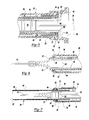
- FIG. 3 is a sectional elevation view thereof
- FIG. 4 is a sectional view thereof following actuation of the shield system of the device
- FIG. 5 is an enlarged sectional view of the proximal portion of the device prior to actuation of the shield system
- FIG. 6 is an enlarged sectional view showing a portion of the device, including the distal portion of a syringe holder of the device, prior to actuation of the shield system;
- FIG. 7 is an enlarged sectional view showing a portion of the device including the distal portion of the syringe holder following actuation of the shield system;
- FIG. 8 is an enlarged sectional view of the proximal portion of the device immediately following actuation of the shield system
- FIG. 9 is an end view of the end fitting.
- FIG. 10 is a side, partially cross-sectioned view of the fitting shown in FIG. 9 .
- FIGS. 1-8 An injection device 10 for injecting a medicament, drug or vaccine into a patient is shown in FIGS. 1-8.
- the device comprises a prefilled or prefillable syringe 12 and a shield assembly coupled to the syringe.
- Syringes are ordinarily comprised of a tubular, generally cylindrical portion 16 , known as a barrel, a needle cannula 18 or other piercing element or a connecting element secured to one end of the barrel, and a piston or stopper 20 slidably positioned within the barrel.
- the needle cannula may be removably secured to the barrel, but is more likely to be permanently secured to the barrel when the barrel is comprised of glass. Glass barrels are commonly used in prefillable syringes, and ordinarily contain a single dose of medication. Prefilled syringes made from plastic are also known to the art. Referring to FIG.
- the shield system disclosed herein is employed in conjunction with a prefillable syringe 12 including a barrel 16 , a cannula such as a needle 18 permanently secured to the barrel, a stopper 20 slidably positioned with the barrel, and a plunger rod 22 engageable with the stopper.
- the syringe barrel 16 includes a radially outwardly extending integral flange 24 , which is normally grasped by the healthcare worker or patient but is used to couple the syringe to the shield system of this invention.
- the shield system 14 includes a tubular holder 26 , a tubular shield 28 coupled to the holder, a coil spring 30 and an end fitting 32 which engages one end of the spring.
- all of the components of the shield system may be made from a semi-rigid plastic material, such as polypropylene.
- the spring is preferably a metal coil spring.
- the fitting is preferably formed of a resilient polymer, such as a thermoplastic elastomer, rubber, synthetic rubber or a rubber blend.
- the holder 26 is preferably comprised of an elongate, generally cylindrical tubular body 34 which defines a generally cylindrical enclosure.
- the holder has proximal and distal open ends 35 and 37 , respectively, which provide access to the enclosure.
- a flange 38 extends radially outwardly from the holder body near the proximal open end 35 thereof. The flange and body of the holder are designed for easy handling as an injection is made. Only one hand should be required for injection.
- the inner surface of the holder enclosure includes a frustoconical surface 40 adjoining the proximal open end 35 as shown in FIGS. 3 and 5.
- a first abutment surface 44 is formed by the holder body in opposing spaced relation to the second abutment surface 42 .
- a second abutment surface 42 is formed at the inner end of this surface, as shown in FIGS. 4 and 5.
- the abutment surfaces 42 and 44 and the outer wall 43 form an annular channel or chamber for receipt of the syringe flange 24 .
- the inner diameter of the holder measured at the abutment surfaces 42 and 44 , is smaller than the distance between the edges or major diameter of the syringe flange 24 .
- the syringe is inserted far enough into the holder such that the flange 24 is located between abutment surfaces 42 , 44 , it is slidably coupled to the holder.
- the frustoconical surface 40 facilitates this insertion.
- the spring 30 urges the syringe flange 24 towards engagement with the first abutment surface 42 as shown in FIG. 5 .
- the gap formed between the abutment surfaces 42 and 44 is preferably greater than the thickness of the syringe flange 24 to allow large tolerances in height to ease clipping (particularly at high speed) and absorb flange thickness variations and system built up tolerances.
- a radial groove 48 or stop is provided on the inside surface of the holder adjacent its distal end 37 .
- the radial groove is provided in an arcuately inwardly projecting distal end portion 50 of the holder, which also serves as a stop member as described below.
- a pair of opposed detents 52 are provided on the holder which prevent retraction of the shield 28 once extended.
- Each of these detents 52 is formed on an axially extending arm 54 which is integral with the holder body 34 and pivotable with respect thereto. (See FIGS. 2, 6 and 7 .)
- the end surface of each detent 52 faces the distal open end 37 of the holder which is substantially perpendicular to the longitudinal axis of the holder.
- An inclined end surface 53 is provided on the opposite side of each detent, and faces the proximal open end 37 .
- the shield 28 is comprised of a substantially cylindrical tubular body 56 .
- the tubular shield 28 preferably has an outside diameter small enough to be positioned within the holder and an inside diameter large enough to receive the barrel 16 of the syringe.
- a stop member 58 in the form of a radially outwardly extending collar or rib is formed integrally on the body 56 of the shield near the distal end thereof.
- a second, radially outwardly extending collar or rib 59 is formed integrally on the shield body 56 towards the proximal end, and defines another stop member 59 .
- the second collar 59 is preferably larger in diameter than the first collar.
- the coil spring 30 has an internal diameter large enough to fit over the proximal end of the shield, such that one end thereof bears against the collar 59 .
- the opposite end of the spring bears against the radially inwardly projecting flange portion 65 of the flange portion or collar 66 of the end fitting 32 as shown in FIG. 5, and the flange portion 66 is biased against the flange 24 of the syringe barrel as shown in FIG. 5, such that the spring 30 is operably biased between the second abutment surface 42 of the holder 26 and the shield 28 .
- the spring 30 causes the shield 28 to move axially upon axial movement of the plunger rod 22 when the stopper 20 is driven against the proximal end of the barrel as shown in FIG. 4, with sufficient force to disengage the rib 58 on the shield from the groove 48 in the holder distal end as described further below.
- Direct engagement of the end fitting 32 or syringe flange 24 and shield, as provided in the preferred embodiment, is not necessary in such an arrangement.
- the operation of the device can be effected whether the shield, spring, end fitting and syringe barrel are directly or indirectly engaged, so long as axial movement of the syringe barrel causes axial movement of the shield.
- the end fitting 32 includes a cylindrical tubular portion 64 which is inserted within the body 34 of the holder as shown in FIG. 8 and surrounds the proximal end of the shield 28 between the rib 59 and the proximal open end as shown in FIG. 5 .
- the end fitting also includes a proximal flange portion 66 including a radially inwardly projecting portion 65 which receives the proximal end of the spring 30 and the flange portion 66 further includes a radially outwardly projecting flange portion 67 which extends into the annular channel or chamber defined by the opposed abutment surfaces 42 and 44 and the outer wall 43 as shown in FIGS.
- the radially outwardly extending flange portion 66 has a diameter greater than the internal diameter of the opposed abutment surfaces 42 and 44 of the chamber adjacent the proximal open end 35 of the holder, such that the shield 28 , spring 30 and fitting 32 are assembled and inserted through the open end 35 as shown in FIG. 5, wherein the radial outer flange portion 67 is biased against the frustoconical surface 40 as described above.
- the syringe barrel 16 is then inserted through the open end 35 or the shield assembly is assembled on the syringe barrel and inserted into the holder 22 as an assembly.
- the spring 30 biases the flange portion 66 of the fitting 32 against the flange 24 of the syringe barrel 16 , which biases the flange 24 against the second abutment surface 42 as shown in FIG. 5 .
- the radially outwardly extending flange portion 67 is thus spaced from the first abutment surface 44 and the needle cannula 18 is exposed as shown in FIGS. 3 and 6 for injection.
- the user further compresses the stopper 20 against the end of the syringe barrel 16 , releasing or decoupling the stop members 48 and 58 and the spring 30 then drives the shield to its extended position as shown in FIG. 7 . This sudden movement of the shield results in vibration of the syringe.
- the syringe flange cannot move to the right in FIG. 8 .
- the flange 24 of the barrel may be driven against the radially outwardly extending portion 67 of the fitting against the first abutment surface 42 . It has been found by the applicant that this vibration and sudden movement may result in damage including cracking of the flange 24 of the barrel 16 which, as set forth above, is generally formed of glass.
- the flange portion 67 includes a plurality of spaced resiliently deformable projections 70 .
- the object of the projections can also be fulfilled by a single continuous resiliently deformable projection.
- the distal end of the resiliently deformable projection or projections 70 have a pointed distal end facing the abutment surface 42 providing improved damping by the projections.
- the resiliently deformable projections are diamond-shaped as best shown in FIG. 9 providing excellent damping of vibration of the syringe flange 24 as shown in FIG. 8, wherein the shield 28 has just been released and the spring 30 is not yet fully expanded.
- the end fitting 32 also avoids direct contact of the coil spring against the fragile glass syringe flange 24 .
- the resiliently deformable projection 70 are integral with the flange portion 66 and the tubular portion 28 for ease of manufacture and assembly.
- the fitting 32 is preferably formed of a resilient polymeric material, such as a thermoplastic elastomer, rubber, synthetic rubber and blends. The improved end fitting 32 thus reduces damage to the flange 24 of the syringe barrel 16 and isolates the flange from the housing 22 .
- the shield 28 is slidably mounted to the holder 26 by inserting the shield through the proximal open end 35 thereof until the first stop member or collar 58 is received in the radial groove or stop member 48 in the holder.
- the spring is inserted through the proximal open end 35 of the holder, and over the shield until it abuts the relative large collar or rib 59 .
- the end fitting 32 is slipped over the exposed end of the spring and pushed through the proximal end 35 of the holder. The spring is substantially compressed during this step.
- the shield 28 is resiliently urged towards the distal end 37 of the holder 26 while the end fitting 32 is urged towards the proximal end thereof by the coil spring 30 .
- Neither element can move due to the engagement of the stop members 48 , 58 , and the annular wall or collar 66 of the end fitting with the abutment surface 42 , respectively.
- the force of the spring 30 is insufficient to cause the disengagement of the shield and holder.
- the shield system 14 receives a syringe 12 of appropriate size through the proximal open end 35 of the holder.
- the system as shown is designed for receiving a syringe 12 including a flange 24 .
- the syringe flange 24 engages the conical surface 40 and is inserted into the shield until the flange 24 snaps behind the first abutment surface 42 in the holder.
- the end fitting 32 is displaced axially slightly during this procedure.
- the needle of the syringe is ordinarily protected by a needle cover or cap (not shown) at this time, it may be safely coupled to the shield system.
- the force required to disengage the rib or stop 58 of the shield from the stop member or internal groove 48 of the holder is greater than the force of the spring plus the force required to expel the contents of the syringe barrel 16 by compressing the stopper 20 .
- the plunger rod 22 is employed to move the stopper 20 through the syringe barrel until the contents of the barrel have been completely expelled. (The needle cover is, of course, removed prior to injection.)
- the contents of the barrel of a prefilled syringe ordinarily corresponds to a single dose of the prescribed medicament.
- the user applies a greater force to the plunger rod 22 than that applied during injection.
- Such force causes axial displacement of the syringe barrel 16 , end fitting 32 , the spring 30 and the shield 28 with respect to the holder 28 .
- the distance between the annular wall or collar 66 of the end fitting (or the flange 24 ) is then sufficient to permit the second stop member rib 58 to move far enough axially to where its retention by the groove 48 is overcome by the force of the spring.
- the first stop member 48 may also be displaced radially inwardly as such sliding occurs if sufficient flexibility of the holder body is provided.
- the spring 30 expands rapidly, causing the shield 28 to slide axially or distally with respect to the holder 26 and syringe barrel.
- the collar 59 moves past the detents 54 , causing them to deflect radially outwardly and then inwardly to their original positions.
- the collar 59 then engages the stop member 50 as shown in FIG. 7 .
- the resiliently deformable projection or projections 70 on the fitting 32 damps vibration of syringe 12 during movement the shield 28 reducing damage to the flange 24 .
- the needle cannula 18 is entirely and permanently enclosed and covered by the shield 28 , as shown in FIGS. 4 and 7.
- the shield cannot be retracted sufficiently to expose the needle tip due to the engagement of the stop member or collar 59 with the detents 52 . It cannot be removed from the holder as the collar 59 cannot move past the stop member 50 .
- the above-described procedure is particularly safe as it can be accomplished using only one hand. No second hand is required to move the shield, push a button or use any other actuating member to release the shield spring. The risk of accidental actuation of the shield through inadvertent contact with an actuating button is also eliminated. Moreover, a one-handed system is simpler for most people to use. It is readily apparent that the shield system can be adapted for use with syringes of various shapes and sizes without major modification.
- the deployment of a shield in response to the axial displacement of a syringe barrel with respect to a holder is a safe and effective way of protecting against needle sticks.
- the preferred embodiment of the invention provides advantages for the user as well as the manufacturer.
- the components are relatively easy to manufacture and assemble. It will be appreciated, however, that modifications can be made without changing the basic mode of operation of the device.
- the stop member 58 , of the shield rather than being in the form of a collar, can simply be the end of the shield.
- the dimensions of each component of the medical device are determined by the specific uses(s) for which it is designed.
Abstract
A medical injection device is provided which includes a shield system and a syringe which may be coupled to the shield system. The shield system includes a syringe holder, a shield telescopically received in the holder and slidably coupled to the holder and an end fitting which isolates the syringe flange from the holder, preventing damage to the flange. A spring resiliently urges the shield from a retracted position to an extended position. Stop members are provided adjacent the distal end of the holder and the proximal end of the shield for maintaining the shield in the retracted position. The syringe is slidably coupled to the holder, and extends within the shield. Axial movement of the syringe with respect to the holder causes disengagement of the stop members, allowing the spring to move the shield to the extended position. Detents are provided on the holder for maintaining the shield in the extended position.
Description
This application is a continuation-in-part application of Ser. No. 09/838,032 filed Apr. 19, 2001, which application is a continuation-in-part application of Ser. No. 09/290,786 filed Apr. 12, 1999, now U.S. Pat. No. 6,319,233, which application claims priority under 35 U.S.C. §119(e) to U.S. provisional patent application Ser. No. 60/082,221 filed Apr. 17, 1998.
1. Field of the Invention
The field of the invention relates to shield systems for protecting against needle sticks, and syringes including such systems.
2. Brief Description of the Related Art
Syringes are well known medical devices for administering medicaments, drugs and vaccines to patients. Prefilled syringes are generally considered as those which are filled with a selected dosage of medicament, drug or vaccine by a pharmaceutical manufacturer for distribution to the end user. They are generally comprised of a glass barrel which contains the medicament, drug or vaccine, and a stopper slidably mounted within the barrel. The distal end of the barrel includes a needle cannula or the like affixed thereto or a connector for a needle cannula assembly such as a Luer fitting. The proximal end of the syringe includes an integral flange and is open to allow the insertion of a stopper of a plunger assembly. The plunger and stopper assembly allows the user to apply manual force to the plunger, causing the medicament, drug or vaccine to be delivered through the needle cannula or other piercing element. The healthcare worker or patient grips the flange and applies pressure to the plunger generally with the thumb.
The use of a sharp-pointed piercing element entails the risk of an accidental needle stick. To avoid such accidents, many prior art hypodermic syringes have included rigid cylindrical safety shields telescoped over the syringe barrel. These shields can be moved between a retracted position, where the needle is exposed for use, to an extended position where the needle is surrounded by the shield. U.S. Pat. Nos. 4,425,120, 4,573,976, 4,850,994 and 4,923,447 disclose various shield systems for hypodermic syringes. The latter two patents disclose shields which may be spring-actuated. It is ordinarily desirable to lock the needle shields in the protected positions, and a number of prior art designs provide for such locking. Some systems, such as those disclosed in U. S. Pat. Nos. 5,201,708, 5,242,240 and 5,318,538 are designed to allow the shields to be retracted from their locked, extended positions.
A shield system for protecting the piercing element of a prefilled syringe is also disclosed in European Publication No. EP 0 740 942 A1. The disclosed system includes a holder which is coupled to the flange of the syringe barrel, and a shield which is telescopically mounted to the holder. Two hands are required to operate this system.
This invention relates to a safety shield system for a syringe, medical cartridge or the like and such a system as used in combination with an assembly capable of functioning as a syringe. In accordance with the preferred embodiment of the system, the user is able to cause the shielding of a needle cannula by simply applying additional pressure to the plunger rod of the syringe following injection of the contents of the syringe barrel. The shield may accordingly be deployed automatically through the use of only one hand. As there is no need to place the hand near the needle for any purpose, the risk of needle stick injury is further reduced.
In accordance with the objects of the invention, a medical device is provided which includes an automatically operable shield system mounted to a syringe barrel. The system includes a tubular holder which defines an enclosure. A tubular needle shield is slidably attached to the holder and preferably telescopically received within the holder. The syringe barrel is received within the holder and shield assembly, preferably within the tubular shield, and the shield is extendable from a retracted position, wherein the needle cannula is exposed to an extended position, wherein the shield encloses the needle cannula following injection. A compressed spring is located within the holder and shield assembly which biases the shield axially toward the extended position. The shield is releaseably retained to the holder, such that upon application of force to the stopper following injection, the shield is released from the retracted position and the spring drives the shield to the extended position. In the disclosed embodiment, the shield includes a stop member adjacent its proximal end and the holder includes a stop member adjacent its distal end which releaseably retains the shield in its retracted position. In the preferred embodiment, the stop member on the holder is an annular internal groove adjacent the distal end of the holder and the stop member on the shield is a radially outwardly extending annular rib. In the most preferred embodiment, the shield includes a further stop member in the form of a second radial rib adjacent the proximal end of the shield which engages the stop member on the holder when the shield is extended to its extended position. The force of the compressed spring by itself is insufficient to disengage the stop member adjacent the distal end of the shield and the stop member on the holder. However, axial movement of the syringe following injection, disengages the stop members and releases the shield. It is intended to cover the needle tip when in the extended position. The syringe barrel is operably coupled to the shield such that sufficient axial movement of the syringe barrel causes axial displacement of the shield sufficient to cause disengagement of the stop members. Such movement of the barrel is ordinarily caused by pressure on the plunger rod of the syringe, driving the stopper against the end of the barrel following complete injection of the contents of the barrel. Upon disengagement of the first and second stop members, the spring causes the shield to move to the extended position.
The proximal end of the holder is preferably adapted to engage and retain the syringe flange upon receipt of the syringe barrel through the proximal end of the holder. The axial or distal movement of the shield is preferably limited by a second abutment surface or rib adjacent the proximal end of the shield which engages a radially inwardly projecting distal end portion of the holder. Such movement could alternatively be limited by a tether connecting the holder and shield. The shield is preferably positioned within the holder such that the spring engages a stop member extending radially outwardly from the shield. The opposite end of the spring can bear against any suitable surface, operably connected to the holder, preferably a flange on the end fitting.
The shield system according to the invention is comprised of a holder, a shield, a spring and an end fitting which receives the spring and which isolates the syringe from the holder, reducing damage to the syringe flange. The tubular shield is adapted for receiving a syringe. The shield is slidably mounted to the holder, and is movable between a retracted position, wherein the shield needle cannula is exposed and an extended position wherein the needle cannula is enclosed. A spring urges the shield towards the extended position. The holder includes a stop member which is engageable with a first stop member of the shield to maintain it in the retracted position. Sufficient axial movement of the syringe barrel causes disengagement of the stop members, allowing the spring to move the shield to the extended position. The holder is engageable with a second portion of the shield axially-spaced from the first portion to prevent decoupling of the shield and holder when the shield moves to the extended position. An end fitting is incorporated in the system to maintain the position of the spring prior to insertion of a syringe into the holder, prevent direct contact of the spring and the syringe flange and isolate the syringe flange from the holder during extension of the shield, preventing damage to the syringe flange.
The tubular holder includes an inwardly opening annular channel or chamber adjacent the open proximal end which receives the flanges of the syringe and fitting. The chamber includes opposed first and second abutment surfaces to retain the flanges. The fitting is located within the holder and includes a tubular portion surrounding the proximal end of the shield and a flange portion located within the housing chamber between the flange of the syringe barrel and the first abutment surface spaced distally from the proximal abutment surface. In the disclosed embodiment, the flange portion of the fitting includes a radially outwardly extending portion and a radially inwardly extending portion. In the preferred embodiment, the radially outwardly extending portion includes at least one and preferably a plurality of resiliently deformable projections extending toward the first abutment surface which isolates the flange of the barrel from the housing and damps impact of the syringe barrel against the first abutment surface, significantly reducing the likelihood of damage such as cracking of the flange of a glass syringe barrel when the shield is extended to the extended position by the spring. In the most preferred embodiment, the resiliently deformable projections are diamond-shaped having a pointed end opposite the first abutment surface and the projections are integral with the fitting preferably formed of a resilient polymer. The radially inwardly projecting portion of the fitting flange portion receives the spring, which is preferably a coil spring biased between the radially inwardly projecting portion of the fitting and a radially outwardly extending rib on the shield which also serves as the second stop.
The shield system facilitates the safe use of prefilled syringes, although it can be adapted for other sharp-pointed injection devices, such as syringes filled just before use and other injection devices. When employed with a syringe, the system allows the contents of the syringe to be expressed in a conventional manner. Continued, and preferably increased pressure on the plunger rod following injection causes the syringe barrel to move axially, thereby axially displacing the shield. Such displacement causes release of the stop members, and the spring to move the shield over the needle of the syringe. Protection against needle sticks is accordingly provided.
FIG. 1 is a top perspective view of a preferred embodiment of the medical device according to the invention as assembled;
FIG. 2 is an exploded, perspective view thereof;
FIG. 3 is a sectional elevation view thereof,
FIG. 4 is a sectional view thereof following actuation of the shield system of the device;
FIG. 5 is an enlarged sectional view of the proximal portion of the device prior to actuation of the shield system;
FIG. 6 is an enlarged sectional view showing a portion of the device, including the distal portion of a syringe holder of the device, prior to actuation of the shield system;
FIG. 7 is an enlarged sectional view showing a portion of the device including the distal portion of the syringe holder following actuation of the shield system;
FIG. 8 is an enlarged sectional view of the proximal portion of the device immediately following actuation of the shield system;
FIG. 9 is an end view of the end fitting; and
FIG. 10 is a side, partially cross-sectioned view of the fitting shown in FIG. 9.
An injection device 10 for injecting a medicament, drug or vaccine into a patient is shown in FIGS. 1-8. The device comprises a prefilled or prefillable syringe 12 and a shield assembly coupled to the syringe.
Syringes are ordinarily comprised of a tubular, generally cylindrical portion 16, known as a barrel, a needle cannula 18 or other piercing element or a connecting element secured to one end of the barrel, and a piston or stopper 20 slidably positioned within the barrel. The needle cannula may be removably secured to the barrel, but is more likely to be permanently secured to the barrel when the barrel is comprised of glass. Glass barrels are commonly used in prefillable syringes, and ordinarily contain a single dose of medication. Prefilled syringes made from plastic are also known to the art. Referring to FIG. 2, the shield system disclosed herein is employed in conjunction with a prefillable syringe 12 including a barrel 16, a cannula such as a needle 18 permanently secured to the barrel, a stopper 20 slidably positioned with the barrel, and a plunger rod 22 engageable with the stopper. The syringe barrel 16 includes a radially outwardly extending integral flange 24, which is normally grasped by the healthcare worker or patient but is used to couple the syringe to the shield system of this invention.
The shield system 14 according to this invention includes a tubular holder 26, a tubular shield 28 coupled to the holder, a coil spring 30 and an end fitting 32 which engages one end of the spring. With the exception of the spring 30 and the fitting 32, all of the components of the shield system may be made from a semi-rigid plastic material, such as polypropylene. The spring is preferably a metal coil spring. The fitting is preferably formed of a resilient polymer, such as a thermoplastic elastomer, rubber, synthetic rubber or a rubber blend.
The holder 26 is preferably comprised of an elongate, generally cylindrical tubular body 34 which defines a generally cylindrical enclosure. The holder has proximal and distal open ends 35 and 37, respectively, which provide access to the enclosure. A flange 38 extends radially outwardly from the holder body near the proximal open end 35 thereof. The flange and body of the holder are designed for easy handling as an injection is made. Only one hand should be required for injection.
The inner surface of the holder enclosure includes a frustoconical surface 40 adjoining the proximal open end 35 as shown in FIGS. 3 and 5. A first abutment surface 44 is formed by the holder body in opposing spaced relation to the second abutment surface 42. A second abutment surface 42 is formed at the inner end of this surface, as shown in FIGS. 4 and 5. As shown in FIGS. 5 and 8, the abutment surfaces 42 and 44 and the outer wall 43 form an annular channel or chamber for receipt of the syringe flange 24. The inner diameter of the holder, measured at the abutment surfaces 42 and 44, is smaller than the distance between the edges or major diameter of the syringe flange 24. Accordingly, once the syringe is inserted far enough into the holder such that the flange 24 is located between abutment surfaces 42, 44, it is slidably coupled to the holder. The frustoconical surface 40 facilitates this insertion. The spring 30 urges the syringe flange 24 towards engagement with the first abutment surface 42 as shown in FIG. 5. The gap formed between the abutment surfaces 42 and 44 is preferably greater than the thickness of the syringe flange 24 to allow large tolerances in height to ease clipping (particularly at high speed) and absorb flange thickness variations and system built up tolerances.
A radial groove 48 or stop, best shown in FIGS. 6 and 7, is provided on the inside surface of the holder adjacent its distal end 37. The radial groove is provided in an arcuately inwardly projecting distal end portion 50 of the holder, which also serves as a stop member as described below.
A pair of opposed detents 52 are provided on the holder which prevent retraction of the shield 28 once extended. Each of these detents 52 is formed on an axially extending arm 54 which is integral with the holder body 34 and pivotable with respect thereto. (See FIGS. 2, 6 and 7.) The end surface of each detent 52 faces the distal open end 37 of the holder which is substantially perpendicular to the longitudinal axis of the holder. An inclined end surface 53 is provided on the opposite side of each detent, and faces the proximal open end 37.
The shield 28 is comprised of a substantially cylindrical tubular body 56. The tubular shield 28 preferably has an outside diameter small enough to be positioned within the holder and an inside diameter large enough to receive the barrel 16 of the syringe. As shown in FIGS. 2 and 7, a stop member 58 in the form of a radially outwardly extending collar or rib is formed integrally on the body 56 of the shield near the distal end thereof. A second, radially outwardly extending collar or rib 59 is formed integrally on the shield body 56 towards the proximal end, and defines another stop member 59. The second collar 59 is preferably larger in diameter than the first collar.
The coil spring 30 has an internal diameter large enough to fit over the proximal end of the shield, such that one end thereof bears against the collar 59. The opposite end of the spring bears against the radially inwardly projecting flange portion 65 of the flange portion or collar 66 of the end fitting 32 as shown in FIG. 5, and the flange portion 66 is biased against the flange 24 of the syringe barrel as shown in FIG. 5, such that the spring 30 is operably biased between the second abutment surface 42 of the holder 26 and the shield 28.
The spring 30 causes the shield 28 to move axially upon axial movement of the plunger rod 22 when the stopper 20 is driven against the proximal end of the barrel as shown in FIG. 4, with sufficient force to disengage the rib 58 on the shield from the groove 48 in the holder distal end as described further below. Direct engagement of the end fitting 32 or syringe flange 24 and shield, as provided in the preferred embodiment, is not necessary in such an arrangement. The operation of the device can be effected whether the shield, spring, end fitting and syringe barrel are directly or indirectly engaged, so long as axial movement of the syringe barrel causes axial movement of the shield.
The end fitting 32 includes a cylindrical tubular portion 64 which is inserted within the body 34 of the holder as shown in FIG. 8 and surrounds the proximal end of the shield 28 between the rib 59 and the proximal open end as shown in FIG. 5. As described above, the end fitting also includes a proximal flange portion 66 including a radially inwardly projecting portion 65 which receives the proximal end of the spring 30 and the flange portion 66 further includes a radially outwardly projecting flange portion 67 which extends into the annular channel or chamber defined by the opposed abutment surfaces 42 and 44 and the outer wall 43 as shown in FIGS. 5 and 8 and is located between the first abutment surface 44 and the flange 24 of the syringe barrel 16. The radially outwardly extending flange portion 66 has a diameter greater than the internal diameter of the opposed abutment surfaces 42 and 44 of the chamber adjacent the proximal open end 35 of the holder, such that the shield 28, spring 30 and fitting 32 are assembled and inserted through the open end 35 as shown in FIG. 5, wherein the radial outer flange portion 67 is biased against the frustoconical surface 40 as described above. The syringe barrel 16 is then inserted through the open end 35 or the shield assembly is assembled on the syringe barrel and inserted into the holder 22 as an assembly.
Prior to use, the spring 30 biases the flange portion 66 of the fitting 32 against the flange 24 of the syringe barrel 16, which biases the flange 24 against the second abutment surface 42 as shown in FIG. 5. The radially outwardly extending flange portion 67 is thus spaced from the first abutment surface 44 and the needle cannula 18 is exposed as shown in FIGS. 3 and 6 for injection. Following injection, the user further compresses the stopper 20 against the end of the syringe barrel 16, releasing or decoupling the stop members 48 and 58 and the spring 30 then drives the shield to its extended position as shown in FIG. 7. This sudden movement of the shield results in vibration of the syringe. Further, because the user is pressing against the distal end of the syringe barrel during release of the shield as shown in FIG. 8, the syringe flange cannot move to the right in FIG. 8. Thus, the flange 24 of the barrel may be driven against the radially outwardly extending portion 67 of the fitting against the first abutment surface 42. It has been found by the applicant that this vibration and sudden movement may result in damage including cracking of the flange 24 of the barrel 16 which, as set forth above, is generally formed of glass.
It would therefore be desirable to isolate the flange 24 of the syringe barrel from the holder 26 and damp impact of the syringe flange 24 and the radially outwardly projecting flange portion 67 against the abutment surface 42. This is accomplished in the present invention by providing resiliently deformable projections 70 which extend from the radially outwardly extending flange portion 67 of the fitting toward the first abutment surface 42 as best shown in FIGS. 5 and 8. These projections 70 isolate the flange 24 of the barrel 16 from the holder and prevent damage to the syringe flange 24. In the preferred embodiment, the flange portion 67 includes a plurality of spaced resiliently deformable projections 70. However, as will be understood, the object of the projections can also be fulfilled by a single continuous resiliently deformable projection. Further, in the preferred embodiment, the distal end of the resiliently deformable projection or projections 70 have a pointed distal end facing the abutment surface 42 providing improved damping by the projections. In the most preferred embodiment disclosed, the resiliently deformable projections are diamond-shaped as best shown in FIG. 9 providing excellent damping of vibration of the syringe flange 24 as shown in FIG. 8, wherein the shield 28 has just been released and the spring 30 is not yet fully expanded. As will be understood, the end fitting 32 also avoids direct contact of the coil spring against the fragile glass syringe flange 24. Further, in the most preferred embodiment, the resiliently deformable projection 70 are integral with the flange portion 66 and the tubular portion 28 for ease of manufacture and assembly. In such embodiments, the fitting 32 is preferably formed of a resilient polymeric material, such as a thermoplastic elastomer, rubber, synthetic rubber and blends. The improved end fitting 32 thus reduces damage to the flange 24 of the syringe barrel 16 and isolates the flange from the housing 22.
The assembly and use of this preferred embodiment of the invention will now be described. The shield 28 is slidably mounted to the holder 26 by inserting the shield through the proximal open end 35 thereof until the first stop member or collar 58 is received in the radial groove or stop member 48 in the holder. The spring is inserted through the proximal open end 35 of the holder, and over the shield until it abuts the relative large collar or rib 59. As a final step, prior to providing the shield system to the end user, the end fitting 32 is slipped over the exposed end of the spring and pushed through the proximal end 35 of the holder. The spring is substantially compressed during this step. The shield 28 is resiliently urged towards the distal end 37 of the holder 26 while the end fitting 32 is urged towards the proximal end thereof by the coil spring 30. Neither element can move due to the engagement of the stop members 48, 58, and the annular wall or collar 66 of the end fitting with the abutment surface 42, respectively. The force of the spring 30 is insufficient to cause the disengagement of the shield and holder.
The shield system 14 receives a syringe 12 of appropriate size through the proximal open end 35 of the holder. The system as shown is designed for receiving a syringe 12 including a flange 24. The syringe flange 24 engages the conical surface 40 and is inserted into the shield until the flange 24 snaps behind the first abutment surface 42 in the holder. The end fitting 32 is displaced axially slightly during this procedure. As the needle of the syringe is ordinarily protected by a needle cover or cap (not shown) at this time, it may be safely coupled to the shield system.
The force required to disengage the rib or stop 58 of the shield from the stop member or internal groove 48 of the holder is greater than the force of the spring plus the force required to expel the contents of the syringe barrel 16 by compressing the stopper 20. The plunger rod 22 is employed to move the stopper 20 through the syringe barrel until the contents of the barrel have been completely expelled. (The needle cover is, of course, removed prior to injection.) The contents of the barrel of a prefilled syringe ordinarily corresponds to a single dose of the prescribed medicament.
Following removal of the needle 18 from the patient, the user applies a greater force to the plunger rod 22 than that applied during injection. Such force causes axial displacement of the syringe barrel 16, end fitting 32, the spring 30 and the shield 28 with respect to the holder 28. The distance between the annular wall or collar 66 of the end fitting (or the flange 24) is then sufficient to permit the second stop member rib 58 to move far enough axially to where its retention by the groove 48 is overcome by the force of the spring. The first stop member 48 may also be displaced radially inwardly as such sliding occurs if sufficient flexibility of the holder body is provided.
Once the rib 58 and groove 48 are disengaged, the spring 30 expands rapidly, causing the shield 28 to slide axially or distally with respect to the holder 26 and syringe barrel. The collar 59 moves past the detents 54, causing them to deflect radially outwardly and then inwardly to their original positions. The collar 59 then engages the stop member 50 as shown in FIG. 7. The resiliently deformable projection or projections 70 on the fitting 32 damps vibration of syringe 12 during movement the shield 28 reducing damage to the flange 24. Upon such engagement, the needle cannula 18 is entirely and permanently enclosed and covered by the shield 28, as shown in FIGS. 4 and 7. The shield cannot be retracted sufficiently to expose the needle tip due to the engagement of the stop member or collar 59 with the detents 52. It cannot be removed from the holder as the collar 59 cannot move past the stop member 50.
The above-described procedure is particularly safe as it can be accomplished using only one hand. No second hand is required to move the shield, push a button or use any other actuating member to release the shield spring. The risk of accidental actuation of the shield through inadvertent contact with an actuating button is also eliminated. Moreover, a one-handed system is simpler for most people to use. It is readily apparent that the shield system can be adapted for use with syringes of various shapes and sizes without major modification.
The deployment of a shield in response to the axial displacement of a syringe barrel with respect to a holder is a safe and effective way of protecting against needle sticks. The preferred embodiment of the invention, as described above, provides advantages for the user as well as the manufacturer. The components are relatively easy to manufacture and assemble. It will be appreciated, however, that modifications can be made without changing the basic mode of operation of the device. For example, the stop member 58, of the shield, rather than being in the form of a collar, can simply be the end of the shield. The dimensions of each component of the medical device are determined by the specific uses(s) for which it is designed.
It will be appreciated and understood by those skilled in the art that further and additional revisions to the invention may be devised without departing from the spirit and scope of the appended claims, the invention not being limited to the specific embodiment shown.
Claims (22)
1. An injection device, comprising:
a generally cylindrical tubular barrel including a first end having a needle cannula having a sharp distal end and a second open end having a radial flange adjacent said second open end;
a tubular holder surrounding said barrel including a first open end adjacent said first end of said barrel spaced from said sharp distal end of said needle cannula and a second open end having a chamber receiving said flange of said barrel, said chamber having an abutment surface facing said flange of said barrel;
a tubular shield releaseably retained by said holder located within said holder surrounding at least a portion of said barrel including a first open end and a second open end, said tubular shield axially moveable with respect to said barrel between a retracted position, wherein said sharp distal end of said needle cannula is exposed, to an extended position, wherein said sharp distal end of said needle cannula is enclosed by said shield;
a fitting within said tubular holder having a tubular portion surrounding said tubular shield and a radial flange portion located within said chamber of said tubular holder between said flange of said barrel and said abutment surface of said chamber having at least one resiliently deformable projection extending toward said abutment surface;
and a spring operably biased between said shield and said holder urging said shield from said retracted position toward said extended position when said shield is released from said tubular holder, whereby said resiliently deformable projection on said flange portion of said fitting damps movement of said flange of said barrel in said chamber, reducing damage to said flange of said barrel.
2. The injection device as defined in claim 1 , wherein said resiliently deformable projection comprises a plurality of projections circumferentially spaced around said flange portion of said insert extending toward said abutment surface of said chamber.
3. The injection device as defined in claim 2 , wherein said plurality of projections are integral with said flange portion of said fitting and said fitting is formed of a resilient polymer.
4. The injection device as defined in claim 2 , wherein said plurality of projections are diamond-shaped each having a pointed distal end.
5. The injection device as defined in claim 1 , wherein said tubular shield includes a radially outwardly extending rib and said spring is biased between said rib of said shield and said insert.
6. The injection device as defined in claim 5 , wherein said insert includes an inwardly projecting radial portion and said spring is biased between said rib of said tubular shield and said radial portion of said insert.
7. The injection device as defined in claim 1 , wherein said holder includes a first stop member adjacent said first open end and said tubular shield includes a first stop member adjacent said first open end of said tubular shield, wherein said first stop members of said holder and said shield releaseably retain said shield in said retracted position.
8. The injection device as defined in claim 7 , wherein said tubular shield includes a second stop member axially spaced from said first stop member arresting movement of said tubular shield towards said extended position.
9. The injection device as defined in claim 8 , wherein said tubular holder includes a second stop member adjacent to but spaced from said first stop member which prevents retraction of said shield from said extended position enclosing said needle cannula sharp distal end.
10. The injection device as defined in claim 1 , wherein said injection device includes a stopper in said barrel telescopically moveable through said barrel to inject fluid through said needle cannula and a plunger attached to said stopper extending through said second open end of said barrel, whereby force applied to said stopper against a reduced diameter end portion of said barrel applies force to said barrel, releasing said tubular shield.
11. An injection device, comprising:
a generally cylindrical tubular barrel formed of glass including a first reduced diameter end portion having a needle cannula attached thereto having a sharp distal end and a second open end having an integral radial flange adjacent said second open end;
a stopper located in said barrel telescopically moveable through said barrel and a plunger attached to said stopper extending through said second open end of said barrel;
a tubular holder surrounding said barrel including a first open end adjacent said first open end of said barrel and a second open end having a chamber receiving said flange of said barrel, said chamber having an abutment surface facing said flange of said barrel;
a tubular shield located within said tubular holder surrounding at least a portion of said barrel releaseably retained by said holder including a first open end and a second open end, said tubular shield axially moveable with respect to said barrel between a retracted position, wherein said sharp distal end of said needle cannula is exposed, to an extended position, wherein said sharp distal end of said needle cannula is enclosed by said shield;
a fitting located within said tubular holder including a tubular portion surrounding said tubular shield and a radial flange portion located within said chamber of said holder between said flange of said tubular barrel and said abutment surface of said chamber, wherein said flange portion of said fitting includes at least one resiliently deformable projection extending toward said abutment surface of said chamber; and
a coil spring surrounding said tubular shield adjacent said second end resiliently biased between said shield and said flange portion of said fitting urging said shield from said retracted position toward said extending position when said shield is released, whereby said resiliently deformable projection on said flange portion of said fitting damps movement of said flange of said barrel in said chamber, reducing damage to said flange of said barrel.
12. The injection device as defined in claim 11 , wherein said chamber in said holder includes a second abutment surface having a diameter less than an outside diameter of said flange of said barrel, retaining said flange in said chamber.
13. The injection device as defined in claim 12 , wherein said second open end of said tubular holder includes an inwardly tapered surface permitting assembly of said flange of said barrel in said chamber.
14. The injection device as defined in claim 11 , wherein said tubular shield includes a radially outwardly projecting rib spaced from said second open end of said shield and said coil spring is biased between said radially outwardly projecting rib of said shield and said flange portion of said fitting.
15. The injection device as defined in claim 11 , wherein said tubular holder includes a stop member adjacent said first open end and said tubular shield includes a complimentary stop member adjacent said first open end and said stop members releaseably retaining said shield in said retracted position.
16. The injection device as defined in claim 11 , wherein said at least one resiliently deformable projection comprises a plurality of projections circumferentially spaced around said flange portion of said insert.
17. The injection device as defined in claim 16 , wherein said plurality of spaced projections are integral with said flange portion of said fitting and said fitting is formed of a resilient polymer.
18. The injection device as defined in claim 16 , wherein said plurality of projections are diamond-shaped each having a pointed distal end.
19. An injection device, comprising:
a generally cylindrical tubular barrel including a reduced diameter first open end having a needle cannula secured thereto having a sharp distal end and a second open end having a radial flange adjacent said second open end;
a tubular holder surrounding said barrel including a first open end adjacent said first open end of said barrel and a second open end having a chamber therein receiving said flange of said barrel, said chamber having opposed first and second abutment surfaces, wherein said first abutment surface faces said flange of said barrel;
a tubular shield located within said tubular holder surrounding at least a portion of said barrel releaseably retained by said holder including a first open end and a second open end, said tubular shield axially moveable with respect to said barrel between a retracted position, wherein said needle cannula is exposed, to an extended position, wherein said needle cannula is enclosed by said shield;
a fitting within said tubular holder having a flange portion located within said chamber of said tubular holder between said flange of said barrel and said first abutment surface including a plurality of resiliently deformable projections circumferentially spaced around said flange portion; and
a spring resiliently biased between said shield and said insert biasing said flange of said barrel against said second abutment surface of said chamber when said shield is in said retracted position, whereby said resilient projections damp movement of said flange of said barrel in said chamber, reducing damage to said flange, when said shield is extended to said extended position.
20. The injection device as defined in claim 19 , wherein said plurality of projections are integral with said flange portion of said fitting and said fitting is formed of a resilient polymer.
21. The injection device as defined in claim 19 , wherein said plurality of projections on said flange portion of said fitting are diamond-shaped each having a pointed distal end.
22. The injection device as defined in claim 19 , wherein said chamber include a gap formed between opposed first and second abutment surfaces has a dimension greater than the thickness of the flange of said barrel.
Priority Applications (8)
| Application Number | Priority Date | Filing Date | Title |
|---|---|---|---|
| US09/876,710 US6679864B2 (en) | 1998-04-17 | 2001-06-07 | Safety shield system for prefilled syringes |
| US10/131,363 US6616639B2 (en) | 1998-04-17 | 2002-04-24 | Safety shield system for syringes |
| ES02741933T ES2256489T3 (en) | 2001-06-07 | 2002-06-07 | SECURITY PROTECTION SYSTEM FOR SYRINGES PREVIOUSLY FULL. |
| AT02741933T ATE318628T1 (en) | 2001-06-07 | 2002-06-07 | PROTECTIVE SLEEVE FOR PRE-FILLED SYRINGES |
| JP2003501531A JP4176630B2 (en) | 2001-06-07 | 2002-06-07 | Safety shielding system for prefilled syringes |
| EP02741933A EP1392379B1 (en) | 2001-06-07 | 2002-06-07 | Safety shield system for prefilled syringes |
| PCT/US2002/018235 WO2002098494A2 (en) | 2001-06-07 | 2002-06-07 | Safety shield system for prefilled syringes |
| DE60209493T DE60209493T2 (en) | 2001-06-07 | 2002-06-07 | PROTECTIVE SLEEVE FOR PRE-FILLED SPRAYING |
Applications Claiming Priority (4)
| Application Number | Priority Date | Filing Date | Title |
|---|---|---|---|
| US8222198P | 1998-04-17 | 1998-04-17 | |
| US09/290,786 US6319233B1 (en) | 1998-04-17 | 1999-04-12 | Safety shield system for prefilled syringes |
| US09/838,032 US6719730B2 (en) | 1998-04-17 | 2001-04-19 | Safety shield system for prefilled syringes |
| US09/876,710 US6679864B2 (en) | 1998-04-17 | 2001-06-07 | Safety shield system for prefilled syringes |
Related Parent Applications (1)
| Application Number | Title | Priority Date | Filing Date |
|---|---|---|---|
| US09/838,032 Continuation-In-Part US6719730B2 (en) | 1998-04-17 | 2001-04-19 | Safety shield system for prefilled syringes |
Related Child Applications (2)
| Application Number | Title | Priority Date | Filing Date |
|---|---|---|---|
| US88581501A Continuation | 1998-04-17 | 2001-06-20 | |
| US10/131,363 Continuation US6616639B2 (en) | 1998-04-17 | 2002-04-24 | Safety shield system for syringes |
Publications (2)
| Publication Number | Publication Date |
|---|---|
| US20030050607A1 US20030050607A1 (en) | 2003-03-13 |
| US6679864B2 true US6679864B2 (en) | 2004-01-20 |
Family
ID=25368403
Family Applications (1)
| Application Number | Title | Priority Date | Filing Date |
|---|---|---|---|
| US09/876,710 Expired - Lifetime US6679864B2 (en) | 1998-04-17 | 2001-06-07 | Safety shield system for prefilled syringes |
Country Status (7)
| Country | Link |
|---|---|
| US (1) | US6679864B2 (en) |
| EP (1) | EP1392379B1 (en) |
| JP (1) | JP4176630B2 (en) |
| AT (1) | ATE318628T1 (en) |
| DE (1) | DE60209493T2 (en) |
| ES (1) | ES2256489T3 (en) |
| WO (1) | WO2002098494A2 (en) |
Cited By (28)
| Publication number | Priority date | Publication date | Assignee | Title |
|---|---|---|---|---|
| US20020193747A1 (en) * | 2000-11-03 | 2002-12-19 | Pascal Denolly | Injection syringe with mobile needle guard |
| US20040127857A1 (en) * | 2002-12-31 | 2004-07-01 | Eli Shemesh | Needle protector device |
| US20040133159A1 (en) * | 2003-01-07 | 2004-07-08 | Haider M. Ishaq | Disposable injection device |
| US20050015055A1 (en) * | 2003-07-18 | 2005-01-20 | Chang-Ming Yang | Sterilized safety syringe |
| WO2005025637A2 (en) | 2003-09-17 | 2005-03-24 | Dali Medical Devices Ltd. | Automatic needle device |
| US20050080383A1 (en) * | 2003-02-27 | 2005-04-14 | Kevin Woehr | Safety syringes |
| US20050113750A1 (en) * | 2003-11-21 | 2005-05-26 | Targell David J. | Safety needle |
| US20050148943A1 (en) * | 2002-02-11 | 2005-07-07 | Stephane Chevalier | Safe support device for a syringe and an assembly comprising such a device and a syringe |
| US20080125717A1 (en) * | 2006-06-16 | 2008-05-29 | Ming-Jeng Shue | Intravenous catheter introducing device |
| US20080132846A1 (en) * | 2006-11-30 | 2008-06-05 | Ming-Jeng Shue | Intravenous catheter introducing device |
| US20100063455A1 (en) * | 2008-09-10 | 2010-03-11 | Moyer Scott A | Safety needle assembly and methods |
| US20100179487A1 (en) * | 2007-04-13 | 2010-07-15 | Woehr Kevin P | Safety syringe |
| US20100234811A1 (en) * | 2006-12-22 | 2010-09-16 | Novo Nordisk A/S | Shieldable needle assembly with biased safety shield |
| US20100256570A1 (en) * | 2007-09-25 | 2010-10-07 | Becton Dickinson France S.A.S. | Autoinjector received in external socket |
| US20100262086A1 (en) * | 2005-08-25 | 2010-10-14 | Don Millerd | Passive Safety System with Pre-Filled Cartridge |
| US7985216B2 (en) | 2004-03-16 | 2011-07-26 | Dali Medical Devices Ltd. | Medicinal container engagement and automatic needle device |
| US20110202011A1 (en) * | 2008-08-28 | 2011-08-18 | Owen Mumford Limited | Autoinjection devices |
| US8128594B1 (en) * | 2010-11-03 | 2012-03-06 | Chang li-feng | Safety syringe |
| US8376998B2 (en) | 2003-09-17 | 2013-02-19 | Elcam Medical Agricultural Cooperative Association Ltd. | Automatic injection device |
| US8512295B2 (en) | 2010-08-19 | 2013-08-20 | West Pharmaceutical Services, Inc. | Rigid needle shield |
| US20140135706A1 (en) * | 2008-06-02 | 2014-05-15 | Sta-Med, Llc | Needle cover |
| US20160067410A1 (en) * | 2013-05-17 | 2016-03-10 | Carrtech Llc | Filtering Needle Cap |
| US9694140B2 (en) | 2010-06-23 | 2017-07-04 | Sta-Med, Llc | Automatic-locking safety needle covers and methods of use and manufacture |
| US9848810B2 (en) | 2011-05-31 | 2017-12-26 | Sta-Med, Llc | Blood collection safety devices and methods of use and manufacture |
| US20180064875A1 (en) * | 2011-12-15 | 2018-03-08 | Shl Group Ab | Auto-Injection Device |
| US10300218B2 (en) * | 2017-03-22 | 2019-05-28 | Shl Medical Ag | Safety assembly for a medical delivery device |
| USD952841S1 (en) | 2019-11-01 | 2022-05-24 | Tech Group Europe Limited | Syringe housing of a syringe injection safety device |
| US11857768B1 (en) | 2022-10-01 | 2024-01-02 | CARRTECH Corp. | Filtering needle assembly with seal plug |
Families Citing this family (46)
| Publication number | Priority date | Publication date | Assignee | Title |
|---|---|---|---|---|
| US6616639B2 (en) * | 1998-04-17 | 2003-09-09 | Becton, Dickinson And Company | Safety shield system for syringes |
| JP4593714B2 (en) * | 2000-02-10 | 2010-12-08 | 株式会社根本杏林堂 | Syringe outer cylinder, syringe holder, syringe piston and piston holder |
| US6776777B2 (en) * | 2002-05-10 | 2004-08-17 | Becton, Dickinson And Company | Passive safety shield system for injection devices |
| FR2852851B1 (en) * | 2003-03-25 | 2006-01-06 | Sedat | NEEDLE PROTECTION DEVICE FOR SYRINGE, AND INJECTION DEVICE COMPRISING SYRINGE AND PROTECTIVE DEVICE |
| FR2861310B1 (en) * | 2003-10-22 | 2006-09-22 | Plastef Investissements | SECURE INJECTION SYRINGE DEVICE |
| US7101351B2 (en) * | 2003-11-03 | 2006-09-05 | Becton, Dickinson And Company | Safety device for a syringe |
| US20050096597A1 (en) * | 2003-11-03 | 2005-05-05 | Becton, Dickinson And Company | Safety shield system for a syringe |
| US7468054B2 (en) * | 2003-11-03 | 2008-12-23 | Becton, Dickinson And Company | Safety shield system for a syringe |
| US7497847B2 (en) * | 2003-11-03 | 2009-03-03 | Becton, Dickinson And Company | Safety shield system for a syringe |
| US7344517B2 (en) * | 2004-01-20 | 2008-03-18 | Becton, Dickinson And Company | Syringe having a retractable needle |
| US20050159706A1 (en) * | 2004-01-20 | 2005-07-21 | Becton, Dickinson And Company | Medical syringe with safety shield system |
| US7604613B2 (en) * | 2004-01-20 | 2009-10-20 | Beckton, Dickinson And Company | Syringe having a retractable needle |
| US20050159709A1 (en) * | 2004-01-20 | 2005-07-21 | Becton, Dickinson And Company | Safety shield system for a plastic syringe |
| US7198617B2 (en) * | 2004-11-05 | 2007-04-03 | Visual Connection, Inc. | Passively guarded, fillable injection syringe |
| US8062252B2 (en) * | 2005-02-18 | 2011-11-22 | Becton, Dickinson And Company | Safety shield system for a syringe |
| US7905868B2 (en) | 2006-08-23 | 2011-03-15 | Medtronic Minimed, Inc. | Infusion medium delivery device and method with drive device for driving plunger in reservoir |
| CA2550114C (en) | 2005-06-20 | 2013-11-19 | Sherwood Services, Ag | Safety shield for medical needles |
| JP4943690B2 (en) * | 2005-10-27 | 2012-05-30 | 前田産業株式会社 | Syringe holder and syringe |
| ATE549294T1 (en) * | 2005-12-09 | 2012-03-15 | Obducat Ab | DEVICE AND METHOD FOR TRANSFER OF PATTERN WITH INTERMEDIATE STAMP |
| US7963954B2 (en) * | 2007-04-30 | 2011-06-21 | Medtronic Minimed, Inc. | Automated filling systems and methods |
| EP2146760B1 (en) | 2007-04-30 | 2018-10-10 | Medtronic MiniMed, Inc. | Reservoir filling, bubble management, and infusion medium delivery systems and methods with same |
| FR2922455B1 (en) * | 2007-10-23 | 2010-10-29 | Plastef Investissements | SYRINGE DEVICE COMPRISING A SYRINGE BODY AND A SUPPORT SLEEVE. |
| FR2926727B1 (en) | 2008-01-28 | 2010-12-24 | Becton Dickinson France | DEVICE FOR PROTECTING AN INJECTION APPARATUS, IN PARTICULAR A MEDICAL INJECTION APPARATUS SUCH AS A SERIGUE |
| DE202009011253U1 (en) * | 2009-08-18 | 2010-12-30 | Schwarzbich, Jörg | Medical cannula |
| GB2479928A (en) * | 2010-04-30 | 2011-11-02 | R5 Pharmaceuticals Ltd | Holder for a drug delivery device |
| FR2962915B1 (en) * | 2010-07-26 | 2012-12-28 | Marc Brunel | SECURE INJECTION DEVICE FOR SINGLE USE |
| US20120123349A1 (en) * | 2010-11-15 | 2012-05-17 | Thomas Chun | Syringe sharp tip guard |
| US9022990B2 (en) | 2011-04-04 | 2015-05-05 | Tech Group Europe Limited | Needle safety shield |
| JP5922760B2 (en) * | 2011-04-05 | 2016-05-24 | エス・ホー・エル・グループ・アクチボラゲットShl Group Ab | Drug delivery device having locking mechanism with lever |
| US9050416B2 (en) | 2012-11-01 | 2015-06-09 | Tech Group Europe Limited | Needle Safety device with floating ring |
| CN107635472A (en) | 2015-06-19 | 2018-01-26 | 神经系统分析公司 | Transcranial doppler detector |
| US11589836B2 (en) | 2016-01-05 | 2023-02-28 | Novasignal Corp. | Systems and methods for detecting neurological conditions |
| WO2017120388A1 (en) | 2016-01-05 | 2017-07-13 | Neural Analytics, Inc. | Systems and methods for determining clinical indications |
| CN108778141A (en) | 2016-01-05 | 2018-11-09 | 神经系统分析公司 | Integrated probe structure |
| US20170307420A1 (en) * | 2016-04-25 | 2017-10-26 | Neural Analytics, Inc. | Probe structure |
| EP3678560A4 (en) * | 2017-09-09 | 2021-05-19 | June Medical IP, LLC | Passive safety intraosseous device |
| WO2023057578A1 (en) | 2021-10-08 | 2023-04-13 | Roncadelle Operations Srl | Passive safety syringe |
| EP4201451A1 (en) * | 2021-12-24 | 2023-06-28 | Becton Dickinson France | Safety device for shielding an injection needle of a medical container, and an injection device including this safety device |
| EP4201452A1 (en) * | 2021-12-24 | 2023-06-28 | Becton Dickinson France | Safety device for shielding an injection needle of a medical container, and an injection device including this safety device |
| EP4201447A1 (en) * | 2021-12-24 | 2023-06-28 | Becton Dickinson France | Safety device for shielding an injection needle of a medical container, and an injection device including this safety device |
| EP4201453A1 (en) * | 2021-12-24 | 2023-06-28 | Becton Dickinson France | Safety device for shielding an injection needle of a medical container, and an injection device including this safety device |
| EP4201449A1 (en) * | 2021-12-24 | 2023-06-28 | Becton Dickinson France | Safety device for shielding an injection needle of a medical container, and an injection device including this safety device |
| EP4201450A1 (en) * | 2021-12-24 | 2023-06-28 | Becton Dickinson France | Safety device for shielding an injection needle of a medical container, and an injection device including this safety device |
| EP4201448A1 (en) * | 2021-12-24 | 2023-06-28 | Becton Dickinson France | Safety device for shielding an injection needle of a medical container, and an injection device including this safety device |
| EP4201454A1 (en) * | 2021-12-24 | 2023-06-28 | Becton Dickinson France | Safety device for shielding an injection needle of a medical container, and an injection device including this safety device |
| EP4201455A1 (en) * | 2021-12-24 | 2023-06-28 | Becton Dickinson France | Safety device for shielding an injection needle of a medical container, and an injection device including this safety device |
Citations (154)
| Publication number | Priority date | Publication date | Assignee | Title |
|---|---|---|---|---|
| US2023289A (en) | 1934-10-11 | 1935-12-03 | Howard A Pringle | Aseptic pack |
| US2801741A (en) | 1954-08-16 | 1957-08-06 | C Dewitt Lukens Surgical Mfg C | Sterile container and ligature package |
| US2851157A (en) | 1957-07-05 | 1958-09-09 | George J Christman | Hypodermic syringe holder |
| US2876770A (en) | 1955-10-10 | 1959-03-10 | Raymond A White | Shielded hypodermic syringe |
| US3076455A (en) | 1958-12-19 | 1963-02-05 | Robert K Mcconnaughey | Holder for hypodermic syringe cartridges |
| US4068661A (en) | 1975-02-12 | 1978-01-17 | Bunder Glas Gmbh | Injection syringe with separate one-piece finger rest |
| US4285105A (en) | 1978-09-29 | 1981-08-25 | Union Carbide Corporation | Colored interlocking closure strips |
| US4361149A (en) | 1977-08-27 | 1982-11-30 | Bunder Glas Gmbh | Injection syringe |
| US4425120A (en) | 1982-04-15 | 1984-01-10 | Sampson Norma A | Shielded hypodermic syringe |
| US4573976A (en) | 1984-05-24 | 1986-03-04 | Dolores A. Smith | Shielded needle |
| US4585445A (en) | 1985-08-19 | 1986-04-29 | Sterling Drug Inc. | Hypodermic syringe holder for use with disposal ampoules |
| US4598820A (en) | 1984-10-31 | 1986-07-08 | Murphy Robert H | Spring for tubular IC carriers |
| US4631057A (en) | 1985-12-17 | 1986-12-23 | Dolores A. Smith | Shielded needle |
| US4695274A (en) | 1986-01-31 | 1987-09-22 | Fox Richard L | Protected hypodermic needle |
| US4723943A (en) | 1986-12-31 | 1988-02-09 | Montana Deaconess Medical Center | Sheathed syringe |
| US4723945A (en) | 1984-05-03 | 1988-02-09 | Bunder Glas Gmbh | Hypodermic syringe |
| US4737144A (en) | 1987-03-09 | 1988-04-12 | Choksi Pradip V | Syringe with selectively exposed and enveloped needle |
| US4743233A (en) | 1986-01-23 | 1988-05-10 | Schneider Medical Technologies, Inc. | Safety cap syringe |
| US4747837A (en) | 1987-05-01 | 1988-05-31 | Hauck Martin W | Syringe needle recapping protective device |
| US4758231A (en) | 1987-04-27 | 1988-07-19 | Habley Medical Technology Corporation | Shielded safety syringe |
| US4801295A (en) | 1986-05-22 | 1989-01-31 | Spencer Treesa A | Disposable hypodermic syringe and needle combination having retractable, accident preventing sheath |
| US4804372A (en) | 1987-09-08 | 1989-02-14 | Laico Joseph P | Protective sheath for hypodermic needle |
| US4826491A (en) | 1987-07-27 | 1989-05-02 | Schramm James J | Needle bearing medical device with three-position shield |
| US4840185A (en) | 1988-02-17 | 1989-06-20 | Manuel Hernandez | Blood sampling device with shield |
| US4850994A (en) | 1985-10-11 | 1989-07-25 | Physionic Gesellschaft fur Medizin-und, Systemtechnik GmbH | Hypodermic syringe |
| US4863434A (en) | 1988-01-29 | 1989-09-05 | Bayless William B | Automatic needle sheath for disposable syringe |
| US4871355A (en) | 1988-05-17 | 1989-10-03 | Steven Kikkawa | Injury resistant needle and blood collection tube holder |
| US4874382A (en) | 1987-10-15 | 1989-10-17 | Servetus Partnership | Safety syringe |
| US4892521A (en) | 1988-08-03 | 1990-01-09 | Lincoln Mills, Inc. | Protective cover for hypodermic needle |
| US4894055A (en) | 1988-12-28 | 1990-01-16 | Sudnak Paul J | Needle guard assembly for use with hypodermic syringes and the like |
| US4897083A (en) | 1988-05-09 | 1990-01-30 | Martell Michael D | Syringe needle guard |
| US4900310A (en) | 1988-10-07 | 1990-02-13 | International Medication Systems Limited | Protective device for cannula used to draw blood |
| US4911693A (en) | 1988-10-17 | 1990-03-27 | Paris Frassetti R | Hypodermic syringe needle guard |
| US4917673A (en) | 1988-10-31 | 1990-04-17 | Coplin Allan J | Assembly for the protection against inadvertent puncture by medical needles |
| US4923447A (en) | 1989-02-17 | 1990-05-08 | Morgan Michael W | Syringe assembly |
| US4923445A (en) | 1988-03-01 | 1990-05-08 | Ryan Medical, Inc. | Safety needled medical devices |
| US4927416A (en) | 1987-12-02 | 1990-05-22 | National Medical Device Corporation | User-protective hypodermic syringe holder |
| US4927018A (en) | 1988-12-06 | 1990-05-22 | Herbert Yang | Disposable covered needle safety assembly |
| US4932937A (en) | 1986-11-06 | 1990-06-12 | Bengt Gustavsson | Vessel for safe handling of substances |
| US4947863A (en) | 1988-08-30 | 1990-08-14 | Habley Medical Technology Corporation | Energy-dissipating, safety blood collection tube holder |
| US4985021A (en) | 1989-01-31 | 1991-01-15 | Jeff Straw | Safety enclosure system for medical devices |
| US4994045A (en) | 1990-04-20 | 1991-02-19 | Sherwood Medical Company | Split sleeve safety syringe |
| US4998920A (en) | 1989-10-11 | 1991-03-12 | Delores Johnson | Protective assembly for hypodermic syringe devices |
| US4998924A (en) | 1989-07-25 | 1991-03-12 | Sherwood Medical Company | Double sleeve safety syringe |
| US5011479A (en) | 1989-10-06 | 1991-04-30 | Son Le | Cover and connector for hypodermic needle |
| US5019051A (en) | 1989-03-02 | 1991-05-28 | Needlepoint Guard, Inc. | Hypodermic needle guard |
| US5024660A (en) | 1987-03-17 | 1991-06-18 | Mcnaughton R David | Syringe shield |
| US5045066A (en) | 1990-06-07 | 1991-09-03 | Smith & Nephew, Inc. | Dental needle with stick resistant protective sleeve |
| US5053018A (en) | 1988-06-28 | 1991-10-01 | Sherwood Medical Company | Combined syringe and needle shield and method of manufacture |
| US5057086A (en) | 1990-07-30 | 1991-10-15 | Dillard Iii John A B | Safety syringe |
| US5057087A (en) | 1989-04-24 | 1991-10-15 | Harmon James E | Hypodermic needle safety system |
| US5059185A (en) | 1988-03-01 | 1991-10-22 | Ryan Medical, Inc. | Safety needled medical devices |
| US5066277A (en) | 1990-07-09 | 1991-11-19 | Safe Medical Devices, Inc. | Protective system for safe disposition of a hypodermic syringe device |
| US5067945A (en) | 1988-03-01 | 1991-11-26 | Ryan Medical, Inc. | Safety needled medical devices capable of one-handed manipulation |
| US5078698A (en) | 1991-02-19 | 1992-01-07 | Sterling Drug Inc. | Axial eject hypodermic syringe holder |
| US5084030A (en) | 1985-07-29 | 1992-01-28 | National Research Development Corporation | Safety device for hypodermic needle or the like |
| US5106379A (en) | 1991-04-09 | 1992-04-21 | Leap E Jack | Syringe shielding assembly |
| US5108378A (en) | 1990-05-09 | 1992-04-28 | Safety Syringes, Inc. | Disposable self-shielding hypodermic syringe |
| US5137521A (en) | 1991-08-19 | 1992-08-11 | Alco Machine & Tool, Inc. | Telescoping safety guard for hypodermic needles and the like |
| USRE34045E (en) | 1987-05-11 | 1992-08-25 | Health Technology Systems, Inc. | Needle protective sleeve |
| US5141500A (en) | 1989-03-02 | 1992-08-25 | Lawrence W. Hake | Hypodermic needle guard |
| US5147303A (en) | 1991-05-23 | 1992-09-15 | Martin Bret C | Disposable safety syringe |
| US5163918A (en) | 1990-07-19 | 1992-11-17 | Nardino Righi | Disposable safety syringe |
| US5169392A (en) | 1988-06-28 | 1992-12-08 | Sherwood Medical Company | Combined syringe and needle shield and method of manufacture |
| US5188614A (en) | 1991-04-04 | 1993-02-23 | Prac-Tech-Cal | Hypodermic syringe needle containment assembly |
| US5197953A (en) | 1991-07-08 | 1993-03-30 | John Colonna | Cap assembly |
| US5201720A (en) | 1992-04-21 | 1993-04-13 | Joseph Borgia | Syringe holding and ejecting assembly |
| US5201708A (en) | 1992-02-03 | 1993-04-13 | Timothy A. Kershenstine | Self-locking safety syringe |
| US5217437A (en) | 1988-06-28 | 1993-06-08 | Sherwood Medical Company | Needle protecting device |
| US5226894A (en) | 1990-09-11 | 1993-07-13 | Sterling Winthrop Inc. | Safety syringe assembly with radially deformable body |
| US5242240A (en) | 1991-10-17 | 1993-09-07 | Minnesota Scientific, Inc. | Clamping device for a surgical retractor |
| US5242420A (en) | 1992-02-03 | 1993-09-07 | Timothy Kershenstine | Self-locking safety syringe |
| US5256154A (en) | 1992-01-31 | 1993-10-26 | Sterling Winthrop, Inc. | Pre-filled plastic syringes and containers and method of terminal sterilization thereof |
| US5279581A (en) | 1990-05-09 | 1994-01-18 | Firth John R | Disposable self-shielding hypodermic syringe |
| US5300040A (en) | 1992-02-03 | 1994-04-05 | Timothy A. Kershenstine | Self-locking safety syringe |
| US5300030A (en) | 1991-05-30 | 1994-04-05 | Owen Mumford Limited | Injection devices |
| US5304149A (en) | 1992-06-12 | 1994-04-19 | Becton, Dickinson And Company | Medical device with a lockable needle shield |
| US5308332A (en) | 1992-06-19 | 1994-05-03 | Square One Medical, Lp | Actuator spring for syringe sheaths |
| US5318547A (en) | 1992-01-15 | 1994-06-07 | Altschuler Bruce R | Sheathed hypodermic needle |
| US5338303A (en) | 1992-09-08 | 1994-08-16 | Design And Engineering Associates | Safety syringes |
| US5338310A (en) | 1992-02-06 | 1994-08-16 | Becton, Dickinson And Company | Needle device having safety indication features |
| US5342309A (en) | 1993-03-05 | 1994-08-30 | Becton, Dickinson And Company | Syringe having safety shield |
| US5342320A (en) | 1993-01-15 | 1994-08-30 | Cameron Robert W | Hypodermic syringe having shielding to prevent accidental injury following use |
| US5344407A (en) | 1993-05-04 | 1994-09-06 | Ryan Dana W | Safety holder for pre-filled disposable syringe cartridge |
| US5346480A (en) | 1992-12-14 | 1994-09-13 | Q-Med, Inc. | Syringe with retractable needle |
| US5348544A (en) | 1993-11-24 | 1994-09-20 | Becton, Dickinson And Company | Single-handedly actuatable safety shield for needles |
| US5350367A (en) | 1990-11-06 | 1994-09-27 | Sterling Winthrop Inc. | Snap together hypodermic syringe holder |
| US5352208A (en) | 1992-11-30 | 1994-10-04 | Robinson Wilbur D | Safe non-reusable hypodermic syringe |
| US5356392A (en) | 1990-05-09 | 1994-10-18 | Safety Syringes, Inc. | Shielded blood collection tube holder |
| US5358491A (en) | 1993-09-13 | 1994-10-25 | Sterling Winthrop Inc. | Cartridge-needle unit having retractable needle |
| US5368578A (en) | 1994-03-10 | 1994-11-29 | Sterling Winthrop Inc. | Hypodermic syringe holder |
| US5380296A (en) | 1990-07-27 | 1995-01-10 | Sterling Winthrop Inc. | Multi-celled safety package, needle guard and safe disposal module for pre-filled medication cartridges |
| US5385555A (en) | 1993-01-08 | 1995-01-31 | Becton, Dickinson And Company | Lockable safety shield for hypodermic syringe |
| US5385557A (en) | 1994-04-04 | 1995-01-31 | Thompson; Clarence J. | Shielding device for a syringe needle |
| US5411489A (en) | 1994-05-06 | 1995-05-02 | Sterling Winthrop Inc. | Pre-filled syringe and pre-filled cartridge having actuating cylinder/plunger rod combination for reducing syringing force |
| US5411488A (en) | 1994-05-06 | 1995-05-02 | Sterling Winthrop Inc. | Pre-filled syringe and pre-filled cartridge having an improved plunger and plunger rod for reducing syringing force |
| US5413563A (en) | 1994-05-06 | 1995-05-09 | Sterling Winthrop Inc. | Pre-filled syringe having a plunger, plunger insert and plunger rod |
| US5417660A (en) | 1992-02-03 | 1995-05-23 | T. A. Kershenstine | Self-locking syringe holder for use with a hypodermic syringe |
| US5437647A (en) | 1990-05-09 | 1995-08-01 | Safety Syringes, Inc. | Disposable self-shielding aspirating syringe |
| US5439450A (en) | 1994-07-18 | 1995-08-08 | Becton, Dickinson And Company | Method of delivering a blood sample to an evacuated receptacle |
| US5447500A (en) | 1993-09-29 | 1995-09-05 | Sterling Winthrop, Inc. | Collar and cartridge-needle unit assembly |
| US5458577A (en) | 1993-07-23 | 1995-10-17 | Nissho Corporation | Composite syringe |
| US5478316A (en) | 1994-02-02 | 1995-12-26 | Becton, Dickinson And Company | Automatic self-injection device |
| US5496286A (en) | 1994-08-17 | 1996-03-05 | Sterling Winthrop | Hypodermic syringe holder with disposable body |
| US5527294A (en) | 1993-05-18 | 1996-06-18 | Safety 1St | Shielded syringe |
| US5562624A (en) | 1994-05-06 | 1996-10-08 | Righi; Nardino | Non-reusable safety syringe |
| US5562626A (en) | 1995-09-11 | 1996-10-08 | Sanpietro; Joseph A. | Safety syringe |
| US5601535A (en) | 1985-07-29 | 1997-02-11 | British Technology Group Ltd. | Safety device for hypodermic needle or the like |
| US5611782A (en) | 1994-07-18 | 1997-03-18 | Becton, Dickinson And Company | Method of delivering a blood sample to an evacuated receptacle |
| US5624400A (en) | 1990-05-09 | 1997-04-29 | Safety Syringes, Inc. | Disposable self-shielding aspirating syringe |
| US5647849A (en) | 1995-09-27 | 1997-07-15 | Becton, Dickinson And Company | Self-contained safety syringe |
| US5658254A (en) | 1995-03-31 | 1997-08-19 | Becton, Dickinson And Company | Syringe having safety needle shield |
| US5681292A (en) | 1996-10-29 | 1997-10-28 | Retrax Safety Systems, Inc. | Retractable needle and syringe combination |
| US5697908A (en) | 1996-09-26 | 1997-12-16 | Becton Dickinson France, S.A. | Lockable safety shield for a prefillable syringe |
| US5709662A (en) | 1996-08-23 | 1998-01-20 | Becton Dickinson France, S.A. | Cartridge for an injection device |
| US5713871A (en) | 1996-08-16 | 1998-02-03 | Stock; David M. | Protective sleeve for hypodermic needle |
| US5733264A (en) | 1997-01-22 | 1998-03-31 | Becton, Dickinson And Company | Shieldable syringe assembly |
| US5735823A (en) | 1992-07-08 | 1998-04-07 | Becton, Dickinson And Company | Safety syringe with I.V. port access |
| EP0845275A2 (en) | 1996-11-29 | 1998-06-03 | Seikagaku Kogyo Kabushiki Kaisha (Seikagaku Corporation) | Holder for a syringe and an injection device using the holder |
| US5769827A (en) | 1994-08-25 | 1998-06-23 | Safeguard Needle International, Inc. | Safety needle apparatus and method |
| US5769822A (en) | 1996-09-13 | 1998-06-23 | Mcgary; R. Kern | Non-reusable retractable safety syringe |
| US5776107A (en) | 1996-12-31 | 1998-07-07 | Delab | Injection device |
| US5788677A (en) | 1995-08-22 | 1998-08-04 | Botich; Michael J. | Pre-filled retractable needle injection ampoules |
| US5792107A (en) | 1909-05-10 | 1998-08-11 | Petrocelli; Pasqualino | Disposable safety syringe |
| US5792122A (en) | 1995-07-12 | 1998-08-11 | Becton Dickinson And Company | Telescoping needle shield |
| US5795336A (en) | 1993-02-11 | 1998-08-18 | Beech Medical Products, Inc. | Automatic needle protector having features for facilitating assembly |
| US5797885A (en) | 1997-07-28 | 1998-08-25 | Rubin; Gregory R. | Apparatus and method for recapping syringe needles |
| US5800403A (en) | 1991-12-23 | 1998-09-01 | Syringe Development Partners L.L.C. | Safety syringe |
| US5800404A (en) | 1989-03-10 | 1998-09-01 | Poulsen; Thomas Edward | Safety hypodermic needle |
| US5800395A (en) | 1996-12-05 | 1998-09-01 | Mdc Investment Holdings, Inc. | Medical device with retractable needle |
| US5810775A (en) | 1997-05-23 | 1998-09-22 | Shaw; Thomas J. | Cap operated retractable medical device |
| US5817064A (en) | 1995-10-23 | 1998-10-06 | American Home Products Corporation | Syringe needle guard |
| US5843036A (en) | 1996-08-23 | 1998-12-01 | Becton Dickinson And Company | Non-dosing cartridge for an injection device |
| US5843041A (en) | 1989-03-02 | 1998-12-01 | Hake; Lawrence W. | Hypodermic needle guard and method to prevent needle stick injuries |
| US5843034A (en) | 1993-10-28 | 1998-12-01 | Lok-Tek International Ltd. | Hypodermic syringe with retractable needle mount |
| US5843047A (en) | 1997-01-29 | 1998-12-01 | Okanogan House, Inc. | Syringe with integral safety cover |
| DE3823266C2 (en) | 1987-07-10 | 1998-12-10 | Jacques Verlier | Spray ampoule |
| US5853390A (en) | 1995-11-10 | 1998-12-29 | Giovanni Freschi | Syringe for hypodermic injections |
| US5855839A (en) * | 1995-05-04 | 1999-01-05 | Sanofi (S.A.) | Process for manufacturing an injection device of the pre-filled type containing a dose of liquid for injection and injection device produced |
| US5868713A (en) | 1997-04-03 | 1999-02-09 | L.O.M. Laboratories Inc. | Pneumatic retractable syringe |
| US5879339A (en) | 1993-06-29 | 1999-03-09 | Saito; Yoshikuni | Hub for syringe, connecting structure of hub, syringe, piston, needle assembly unit, connecting structure between needle assembly unit and syringe, syringe assembly and method of assembling syringe assembly |
| US5882342A (en) | 1997-04-11 | 1999-03-16 | Safety Medical Manufacturing, Inc | Safety medical syringe with retractable needle |
| US5910130A (en) | 1996-09-26 | 1999-06-08 | Becton, Dickinson And Company | Shield and actuator for needles |
| DE19543313C2 (en) | 1995-11-21 | 1999-07-22 | Saueressig Ulrich | Safety cannula |
| US5947936A (en) | 1998-10-23 | 1999-09-07 | Bonds; Michael F. | Syringe with spring biased needle cover |
| US5980494A (en) | 1997-12-22 | 1999-11-09 | Robert Malenchek | Safety syringe |
| US5984899A (en) | 1993-02-11 | 1999-11-16 | Beech Medical Products, Inc. | Needle protector device having a lockable protective cover which is unlockable during actuation |
| US5984898A (en) | 1999-02-17 | 1999-11-16 | Retrax Safety Systems Inc. | Retractable needle and syringe combination |
| US5984906A (en) | 1991-07-12 | 1999-11-16 | Novo Nordisk A/S | Syringe system |
| US6004296A (en) | 1997-09-30 | 1999-12-21 | Becton Dickinson France, S.A. | Lockable safety shield assembly for a prefillable syringe |
| EP0966983A1 (en) | 1998-04-17 | 1999-12-29 | Becton Dickinson and Company | Safety shield system for prefilled syringes |
| US6017329A (en) | 1989-03-02 | 2000-01-25 | Hake; Lawrence W. | Hypodermic needle guard and method to prevent needle stick injuries |
| US6030366A (en) | 1998-11-09 | 2000-02-29 | Safety Syringes, Inc. | Syringe guard system for a unit dose syringe |
| EP1090652A1 (en) | 1999-10-06 | 2001-04-11 | Bünder Glas GmbH | Needle shield for the needle portion of a syringe body |
-
2001
- 2001-06-07 US US09/876,710 patent/US6679864B2/en not_active Expired - Lifetime
-
2002
- 2002-06-07 AT AT02741933T patent/ATE318628T1/en not_active IP Right Cessation
- 2002-06-07 WO PCT/US2002/018235 patent/WO2002098494A2/en active IP Right Grant
- 2002-06-07 EP EP02741933A patent/EP1392379B1/en not_active Expired - Lifetime
- 2002-06-07 DE DE60209493T patent/DE60209493T2/en not_active Expired - Lifetime
- 2002-06-07 ES ES02741933T patent/ES2256489T3/en not_active Expired - Lifetime
- 2002-06-07 JP JP2003501531A patent/JP4176630B2/en not_active Expired - Lifetime
Patent Citations (164)
| Publication number | Priority date | Publication date | Assignee | Title |
|---|---|---|---|---|
| US5792107A (en) | 1909-05-10 | 1998-08-11 | Petrocelli; Pasqualino | Disposable safety syringe |
| US2023289A (en) | 1934-10-11 | 1935-12-03 | Howard A Pringle | Aseptic pack |
| US2801741A (en) | 1954-08-16 | 1957-08-06 | C Dewitt Lukens Surgical Mfg C | Sterile container and ligature package |
| US2876770A (en) | 1955-10-10 | 1959-03-10 | Raymond A White | Shielded hypodermic syringe |
| US2851157A (en) | 1957-07-05 | 1958-09-09 | George J Christman | Hypodermic syringe holder |
| US3076455A (en) | 1958-12-19 | 1963-02-05 | Robert K Mcconnaughey | Holder for hypodermic syringe cartridges |
| US4068661A (en) | 1975-02-12 | 1978-01-17 | Bunder Glas Gmbh | Injection syringe with separate one-piece finger rest |
| US4361149A (en) | 1977-08-27 | 1982-11-30 | Bunder Glas Gmbh | Injection syringe |
| US4285105A (en) | 1978-09-29 | 1981-08-25 | Union Carbide Corporation | Colored interlocking closure strips |
| US4425120A (en) | 1982-04-15 | 1984-01-10 | Sampson Norma A | Shielded hypodermic syringe |
| US4723945A (en) | 1984-05-03 | 1988-02-09 | Bunder Glas Gmbh | Hypodermic syringe |
| US4573976A (en) | 1984-05-24 | 1986-03-04 | Dolores A. Smith | Shielded needle |
| US4598820A (en) | 1984-10-31 | 1986-07-08 | Murphy Robert H | Spring for tubular IC carriers |
| US5084030A (en) | 1985-07-29 | 1992-01-28 | National Research Development Corporation | Safety device for hypodermic needle or the like |
| US5601535A (en) | 1985-07-29 | 1997-02-11 | British Technology Group Ltd. | Safety device for hypodermic needle or the like |
| US4585445A (en) | 1985-08-19 | 1986-04-29 | Sterling Drug Inc. | Hypodermic syringe holder for use with disposal ampoules |
| US4850994A (en) | 1985-10-11 | 1989-07-25 | Physionic Gesellschaft fur Medizin-und, Systemtechnik GmbH | Hypodermic syringe |
| US4631057A (en) | 1985-12-17 | 1986-12-23 | Dolores A. Smith | Shielded needle |
| US4743233A (en) | 1986-01-23 | 1988-05-10 | Schneider Medical Technologies, Inc. | Safety cap syringe |
| US4695274A (en) | 1986-01-31 | 1987-09-22 | Fox Richard L | Protected hypodermic needle |
| US4801295A (en) | 1986-05-22 | 1989-01-31 | Spencer Treesa A | Disposable hypodermic syringe and needle combination having retractable, accident preventing sheath |
| US4932937A (en) | 1986-11-06 | 1990-06-12 | Bengt Gustavsson | Vessel for safe handling of substances |
| US4723943A (en) | 1986-12-31 | 1988-02-09 | Montana Deaconess Medical Center | Sheathed syringe |
| US4737144A (en) | 1987-03-09 | 1988-04-12 | Choksi Pradip V | Syringe with selectively exposed and enveloped needle |
| US5024660A (en) | 1987-03-17 | 1991-06-18 | Mcnaughton R David | Syringe shield |
| US4758231A (en) | 1987-04-27 | 1988-07-19 | Habley Medical Technology Corporation | Shielded safety syringe |
| US4747837A (en) | 1987-05-01 | 1988-05-31 | Hauck Martin W | Syringe needle recapping protective device |
| USRE34045E (en) | 1987-05-11 | 1992-08-25 | Health Technology Systems, Inc. | Needle protective sleeve |
| DE3823266C2 (en) | 1987-07-10 | 1998-12-10 | Jacques Verlier | Spray ampoule |
| US4826491A (en) | 1987-07-27 | 1989-05-02 | Schramm James J | Needle bearing medical device with three-position shield |
| US4804372A (en) | 1987-09-08 | 1989-02-14 | Laico Joseph P | Protective sheath for hypodermic needle |
| US4874382A (en) | 1987-10-15 | 1989-10-17 | Servetus Partnership | Safety syringe |
| US4927416A (en) | 1987-12-02 | 1990-05-22 | National Medical Device Corporation | User-protective hypodermic syringe holder |
| US4863434A (en) | 1988-01-29 | 1989-09-05 | Bayless William B | Automatic needle sheath for disposable syringe |
| US4840185A (en) | 1988-02-17 | 1989-06-20 | Manuel Hernandez | Blood sampling device with shield |
| US4923445A (en) | 1988-03-01 | 1990-05-08 | Ryan Medical, Inc. | Safety needled medical devices |
| US5067945A (en) | 1988-03-01 | 1991-11-26 | Ryan Medical, Inc. | Safety needled medical devices capable of one-handed manipulation |
| US5059185A (en) | 1988-03-01 | 1991-10-22 | Ryan Medical, Inc. | Safety needled medical devices |
| US4897083A (en) | 1988-05-09 | 1990-01-30 | Martell Michael D | Syringe needle guard |
| US4871355A (en) | 1988-05-17 | 1989-10-03 | Steven Kikkawa | Injury resistant needle and blood collection tube holder |
| US5169392A (en) | 1988-06-28 | 1992-12-08 | Sherwood Medical Company | Combined syringe and needle shield and method of manufacture |
| US5217437A (en) | 1988-06-28 | 1993-06-08 | Sherwood Medical Company | Needle protecting device |
| US5053018A (en) | 1988-06-28 | 1991-10-01 | Sherwood Medical Company | Combined syringe and needle shield and method of manufacture |
| US4892521A (en) | 1988-08-03 | 1990-01-09 | Lincoln Mills, Inc. | Protective cover for hypodermic needle |
| US4947863A (en) | 1988-08-30 | 1990-08-14 | Habley Medical Technology Corporation | Energy-dissipating, safety blood collection tube holder |
| US4900310A (en) | 1988-10-07 | 1990-02-13 | International Medication Systems Limited | Protective device for cannula used to draw blood |
| US4911693A (en) | 1988-10-17 | 1990-03-27 | Paris Frassetti R | Hypodermic syringe needle guard |
| US4917673A (en) | 1988-10-31 | 1990-04-17 | Coplin Allan J | Assembly for the protection against inadvertent puncture by medical needles |
| US4927018A (en) | 1988-12-06 | 1990-05-22 | Herbert Yang | Disposable covered needle safety assembly |
| US4894055A (en) | 1988-12-28 | 1990-01-16 | Sudnak Paul J | Needle guard assembly for use with hypodermic syringes and the like |
| US4985021A (en) | 1989-01-31 | 1991-01-15 | Jeff Straw | Safety enclosure system for medical devices |
| US4923447A (en) | 1989-02-17 | 1990-05-08 | Morgan Michael W | Syringe assembly |
| US5019051A (en) | 1989-03-02 | 1991-05-28 | Needlepoint Guard, Inc. | Hypodermic needle guard |
| US5843041A (en) | 1989-03-02 | 1998-12-01 | Hake; Lawrence W. | Hypodermic needle guard and method to prevent needle stick injuries |
| US6017329A (en) | 1989-03-02 | 2000-01-25 | Hake; Lawrence W. | Hypodermic needle guard and method to prevent needle stick injuries |
| US5141500A (en) | 1989-03-02 | 1992-08-25 | Lawrence W. Hake | Hypodermic needle guard |
| US5800404A (en) | 1989-03-10 | 1998-09-01 | Poulsen; Thomas Edward | Safety hypodermic needle |
| US5057087A (en) | 1989-04-24 | 1991-10-15 | Harmon James E | Hypodermic needle safety system |
| US4998924A (en) | 1989-07-25 | 1991-03-12 | Sherwood Medical Company | Double sleeve safety syringe |
| US5011479A (en) | 1989-10-06 | 1991-04-30 | Son Le | Cover and connector for hypodermic needle |
| US4998920A (en) | 1989-10-11 | 1991-03-12 | Delores Johnson | Protective assembly for hypodermic syringe devices |
| US4994045A (en) | 1990-04-20 | 1991-02-19 | Sherwood Medical Company | Split sleeve safety syringe |
| US5616134A (en) | 1990-05-09 | 1997-04-01 | Safety Syringes, Inc. | Disposable self-shielding hypodermic syringe |
| US5624400A (en) | 1990-05-09 | 1997-04-29 | Safety Syringes, Inc. | Disposable self-shielding aspirating syringe |
| US5279581A (en) | 1990-05-09 | 1994-01-18 | Firth John R | Disposable self-shielding hypodermic syringe |
| US5356392A (en) | 1990-05-09 | 1994-10-18 | Safety Syringes, Inc. | Shielded blood collection tube holder |
| US5501672A (en) | 1990-05-09 | 1996-03-26 | Safety Syringes, Inc. | Disposable self-shielding hypodermic syringe |
| US5108378A (en) | 1990-05-09 | 1992-04-28 | Safety Syringes, Inc. | Disposable self-shielding hypodermic syringe |
| US5437647A (en) | 1990-05-09 | 1995-08-01 | Safety Syringes, Inc. | Disposable self-shielding aspirating syringe |
| US5312365A (en) | 1990-05-09 | 1994-05-17 | Firth John R | Disposable self-shielding hypodermic syringe |
| US5045066A (en) | 1990-06-07 | 1991-09-03 | Smith & Nephew, Inc. | Dental needle with stick resistant protective sleeve |
| US5066277A (en) | 1990-07-09 | 1991-11-19 | Safe Medical Devices, Inc. | Protective system for safe disposition of a hypodermic syringe device |
| US5163918A (en) | 1990-07-19 | 1992-11-17 | Nardino Righi | Disposable safety syringe |
| US5380296A (en) | 1990-07-27 | 1995-01-10 | Sterling Winthrop Inc. | Multi-celled safety package, needle guard and safe disposal module for pre-filled medication cartridges |
| US5057086A (en) | 1990-07-30 | 1991-10-15 | Dillard Iii John A B | Safety syringe |
| US5226894A (en) | 1990-09-11 | 1993-07-13 | Sterling Winthrop Inc. | Safety syringe assembly with radially deformable body |
| US5350367A (en) | 1990-11-06 | 1994-09-27 | Sterling Winthrop Inc. | Snap together hypodermic syringe holder |
| US5078698A (en) | 1991-02-19 | 1992-01-07 | Sterling Drug Inc. | Axial eject hypodermic syringe holder |
| US5188614A (en) | 1991-04-04 | 1993-02-23 | Prac-Tech-Cal | Hypodermic syringe needle containment assembly |
| US5106379A (en) | 1991-04-09 | 1992-04-21 | Leap E Jack | Syringe shielding assembly |
| US5147303A (en) | 1991-05-23 | 1992-09-15 | Martin Bret C | Disposable safety syringe |
| US5300030A (en) | 1991-05-30 | 1994-04-05 | Owen Mumford Limited | Injection devices |
| US5197953A (en) | 1991-07-08 | 1993-03-30 | John Colonna | Cap assembly |
| US5984906A (en) | 1991-07-12 | 1999-11-16 | Novo Nordisk A/S | Syringe system |
| US5137521A (en) | 1991-08-19 | 1992-08-11 | Alco Machine & Tool, Inc. | Telescoping safety guard for hypodermic needles and the like |
| US5242240A (en) | 1991-10-17 | 1993-09-07 | Minnesota Scientific, Inc. | Clamping device for a surgical retractor |
| US5800403A (en) | 1991-12-23 | 1998-09-01 | Syringe Development Partners L.L.C. | Safety syringe |
| US5318547A (en) | 1992-01-15 | 1994-06-07 | Altschuler Bruce R | Sheathed hypodermic needle |
| US5256154A (en) | 1992-01-31 | 1993-10-26 | Sterling Winthrop, Inc. | Pre-filled plastic syringes and containers and method of terminal sterilization thereof |
| US5201708A (en) | 1992-02-03 | 1993-04-13 | Timothy A. Kershenstine | Self-locking safety syringe |
| US5318538A (en) | 1992-02-03 | 1994-06-07 | Timothy Kershenstine | Self-locking safety syringe |
| US5300040A (en) | 1992-02-03 | 1994-04-05 | Timothy A. Kershenstine | Self-locking safety syringe |
| US5242420A (en) | 1992-02-03 | 1993-09-07 | Timothy Kershenstine | Self-locking safety syringe |
| US5417660A (en) | 1992-02-03 | 1995-05-23 | T. A. Kershenstine | Self-locking syringe holder for use with a hypodermic syringe |
| US5338310A (en) | 1992-02-06 | 1994-08-16 | Becton, Dickinson And Company | Needle device having safety indication features |
| US5674203A (en) | 1992-02-06 | 1997-10-07 | Becton, Dickinson And Company | Needle device having safety indication features |
| US5201720A (en) | 1992-04-21 | 1993-04-13 | Joseph Borgia | Syringe holding and ejecting assembly |
| US5304149A (en) | 1992-06-12 | 1994-04-19 | Becton, Dickinson And Company | Medical device with a lockable needle shield |
| US5308332A (en) | 1992-06-19 | 1994-05-03 | Square One Medical, Lp | Actuator spring for syringe sheaths |
| US5735823A (en) | 1992-07-08 | 1998-04-07 | Becton, Dickinson And Company | Safety syringe with I.V. port access |
| US5338303A (en) | 1992-09-08 | 1994-08-16 | Design And Engineering Associates | Safety syringes |
| US5352208A (en) | 1992-11-30 | 1994-10-04 | Robinson Wilbur D | Safe non-reusable hypodermic syringe |
| US5346480A (en) | 1992-12-14 | 1994-09-13 | Q-Med, Inc. | Syringe with retractable needle |
| US5385555A (en) | 1993-01-08 | 1995-01-31 | Becton, Dickinson And Company | Lockable safety shield for hypodermic syringe |
| US5342320A (en) | 1993-01-15 | 1994-08-30 | Cameron Robert W | Hypodermic syringe having shielding to prevent accidental injury following use |
| US5795336A (en) | 1993-02-11 | 1998-08-18 | Beech Medical Products, Inc. | Automatic needle protector having features for facilitating assembly |
| US5984899A (en) | 1993-02-11 | 1999-11-16 | Beech Medical Products, Inc. | Needle protector device having a lockable protective cover which is unlockable during actuation |
| US5342309A (en) | 1993-03-05 | 1994-08-30 | Becton, Dickinson And Company | Syringe having safety shield |
| US5344407A (en) | 1993-05-04 | 1994-09-06 | Ryan Dana W | Safety holder for pre-filled disposable syringe cartridge |
| US5527294A (en) | 1993-05-18 | 1996-06-18 | Safety 1St | Shielded syringe |
| US5879339A (en) | 1993-06-29 | 1999-03-09 | Saito; Yoshikuni | Hub for syringe, connecting structure of hub, syringe, piston, needle assembly unit, connecting structure between needle assembly unit and syringe, syringe assembly and method of assembling syringe assembly |
| US5458577A (en) | 1993-07-23 | 1995-10-17 | Nissho Corporation | Composite syringe |
| US5358491A (en) | 1993-09-13 | 1994-10-25 | Sterling Winthrop Inc. | Cartridge-needle unit having retractable needle |
| US5447500A (en) | 1993-09-29 | 1995-09-05 | Sterling Winthrop, Inc. | Collar and cartridge-needle unit assembly |
| US5843034A (en) | 1993-10-28 | 1998-12-01 | Lok-Tek International Ltd. | Hypodermic syringe with retractable needle mount |
| US5348544A (en) | 1993-11-24 | 1994-09-20 | Becton, Dickinson And Company | Single-handedly actuatable safety shield for needles |
| US5478316A (en) | 1994-02-02 | 1995-12-26 | Becton, Dickinson And Company | Automatic self-injection device |
| US5368578A (en) | 1994-03-10 | 1994-11-29 | Sterling Winthrop Inc. | Hypodermic syringe holder |
| US5385557A (en) | 1994-04-04 | 1995-01-31 | Thompson; Clarence J. | Shielding device for a syringe needle |
| US5562624A (en) | 1994-05-06 | 1996-10-08 | Righi; Nardino | Non-reusable safety syringe |
| US5413563A (en) | 1994-05-06 | 1995-05-09 | Sterling Winthrop Inc. | Pre-filled syringe having a plunger, plunger insert and plunger rod |
| US5411488A (en) | 1994-05-06 | 1995-05-02 | Sterling Winthrop Inc. | Pre-filled syringe and pre-filled cartridge having an improved plunger and plunger rod for reducing syringing force |
| US5411489A (en) | 1994-05-06 | 1995-05-02 | Sterling Winthrop Inc. | Pre-filled syringe and pre-filled cartridge having actuating cylinder/plunger rod combination for reducing syringing force |
| US5439450A (en) | 1994-07-18 | 1995-08-08 | Becton, Dickinson And Company | Method of delivering a blood sample to an evacuated receptacle |
| US5611782A (en) | 1994-07-18 | 1997-03-18 | Becton, Dickinson And Company | Method of delivering a blood sample to an evacuated receptacle |
| US5496286A (en) | 1994-08-17 | 1996-03-05 | Sterling Winthrop | Hypodermic syringe holder with disposable body |
| US5769827A (en) | 1994-08-25 | 1998-06-23 | Safeguard Needle International, Inc. | Safety needle apparatus and method |
| US6010487A (en) | 1994-08-25 | 2000-01-04 | Safeguard Needle International, Inc. | Safety needle apparatus and method |
| US5658254A (en) | 1995-03-31 | 1997-08-19 | Becton, Dickinson And Company | Syringe having safety needle shield |
| US6033387A (en) | 1995-05-04 | 2000-03-07 | Sanofi-Synthelabo | Process for manufacturing an injection device of the prefilled type containing a dose of liquid for injection, and injection device produced |
| EP0740942B1 (en) | 1995-05-04 | 1999-08-11 | SANOFI Société Anonyme | Process of manufacturing a prefilled injection device and injection device produced thereby |
| US5855839A (en) * | 1995-05-04 | 1999-01-05 | Sanofi (S.A.) | Process for manufacturing an injection device of the pre-filled type containing a dose of liquid for injection and injection device produced |
| US5792122A (en) | 1995-07-12 | 1998-08-11 | Becton Dickinson And Company | Telescoping needle shield |
| US5788677A (en) | 1995-08-22 | 1998-08-04 | Botich; Michael J. | Pre-filled retractable needle injection ampoules |
| US5562626A (en) | 1995-09-11 | 1996-10-08 | Sanpietro; Joseph A. | Safety syringe |
| US5647849A (en) | 1995-09-27 | 1997-07-15 | Becton, Dickinson And Company | Self-contained safety syringe |
| US5817064A (en) | 1995-10-23 | 1998-10-06 | American Home Products Corporation | Syringe needle guard |
| US5853390A (en) | 1995-11-10 | 1998-12-29 | Giovanni Freschi | Syringe for hypodermic injections |
| DE19543313C2 (en) | 1995-11-21 | 1999-07-22 | Saueressig Ulrich | Safety cannula |
| US5713871A (en) | 1996-08-16 | 1998-02-03 | Stock; David M. | Protective sleeve for hypodermic needle |
| US5709662A (en) | 1996-08-23 | 1998-01-20 | Becton Dickinson France, S.A. | Cartridge for an injection device |
| US5843036A (en) | 1996-08-23 | 1998-12-01 | Becton Dickinson And Company | Non-dosing cartridge for an injection device |
| US5769822A (en) | 1996-09-13 | 1998-06-23 | Mcgary; R. Kern | Non-reusable retractable safety syringe |
| US5910130A (en) | 1996-09-26 | 1999-06-08 | Becton, Dickinson And Company | Shield and actuator for needles |
| US5697908A (en) | 1996-09-26 | 1997-12-16 | Becton Dickinson France, S.A. | Lockable safety shield for a prefillable syringe |
| US5681292A (en) | 1996-10-29 | 1997-10-28 | Retrax Safety Systems, Inc. | Retractable needle and syringe combination |
| EP0845275A2 (en) | 1996-11-29 | 1998-06-03 | Seikagaku Kogyo Kabushiki Kaisha (Seikagaku Corporation) | Holder for a syringe and an injection device using the holder |
| US5800395A (en) | 1996-12-05 | 1998-09-01 | Mdc Investment Holdings, Inc. | Medical device with retractable needle |
| US5776107A (en) | 1996-12-31 | 1998-07-07 | Delab | Injection device |
| US5733264A (en) | 1997-01-22 | 1998-03-31 | Becton, Dickinson And Company | Shieldable syringe assembly |
| US5843047A (en) | 1997-01-29 | 1998-12-01 | Okanogan House, Inc. | Syringe with integral safety cover |
| US5868713A (en) | 1997-04-03 | 1999-02-09 | L.O.M. Laboratories Inc. | Pneumatic retractable syringe |
| US5882342A (en) | 1997-04-11 | 1999-03-16 | Safety Medical Manufacturing, Inc | Safety medical syringe with retractable needle |
| US5810775A (en) | 1997-05-23 | 1998-09-22 | Shaw; Thomas J. | Cap operated retractable medical device |
| US5797885A (en) | 1997-07-28 | 1998-08-25 | Rubin; Gregory R. | Apparatus and method for recapping syringe needles |
| US6193696B1 (en) | 1997-09-30 | 2001-02-27 | Becton Dickinson France, S.A. | Lockable safety shield assembly for a prefillable syringe |
| US6004296A (en) | 1997-09-30 | 1999-12-21 | Becton Dickinson France, S.A. | Lockable safety shield assembly for a prefillable syringe |
| US5980494A (en) | 1997-12-22 | 1999-11-09 | Robert Malenchek | Safety syringe |
| EP0966983A1 (en) | 1998-04-17 | 1999-12-29 | Becton Dickinson and Company | Safety shield system for prefilled syringes |
| US6319233B1 (en) | 1998-04-17 | 2001-11-20 | Becton, Dickinson And Company | Safety shield system for prefilled syringes |
| US5947936A (en) | 1998-10-23 | 1999-09-07 | Bonds; Michael F. | Syringe with spring biased needle cover |
| US6030366A (en) | 1998-11-09 | 2000-02-29 | Safety Syringes, Inc. | Syringe guard system for a unit dose syringe |
| US5984898A (en) | 1999-02-17 | 1999-11-16 | Retrax Safety Systems Inc. | Retractable needle and syringe combination |
| EP1090652A1 (en) | 1999-10-06 | 2001-04-11 | Bünder Glas GmbH | Needle shield for the needle portion of a syringe body |
Cited By (66)
| Publication number | Priority date | Publication date | Assignee | Title |
|---|---|---|---|---|
| US20020193747A1 (en) * | 2000-11-03 | 2002-12-19 | Pascal Denolly | Injection syringe with mobile needle guard |
| US6893423B2 (en) * | 2000-11-03 | 2005-05-17 | Sedat | Injection syringe with mobile needle guard |
| US20080294120A1 (en) * | 2002-02-11 | 2008-11-27 | Sanofi-Aventis | Needle sheathing device with flexible end-piece for syringe |
| US8603043B2 (en) | 2002-02-11 | 2013-12-10 | Sanofi | Needle sheathing device with flexible end-piece for syringe |
| US8308696B2 (en) | 2002-02-11 | 2012-11-13 | Sanofi-Aventis | Needle sheathing device with flexible end-piece for syringe |
| US11135377B2 (en) | 2002-02-11 | 2021-10-05 | Sanofi | Needle sheathing device with flexible end-piece for syringe |
| US20110046605A1 (en) * | 2002-02-11 | 2011-02-24 | Sanofi-Aventis | Needle sheathing device with flexible end-piece for syringe |
| US20050148943A1 (en) * | 2002-02-11 | 2005-07-07 | Stephane Chevalier | Safe support device for a syringe and an assembly comprising such a device and a syringe |
| US7850661B2 (en) * | 2002-02-11 | 2010-12-14 | Sanofi-Aventis | Needle sheathing device with flexible end-piece for syringe |
| US9555196B2 (en) | 2002-02-11 | 2017-01-31 | Sanofi | Needle sheathing device with flexible end-piece for syringe |
| US20040127857A1 (en) * | 2002-12-31 | 2004-07-01 | Eli Shemesh | Needle protector device |
| US6846302B2 (en) * | 2002-12-31 | 2005-01-25 | Teva Medical Ltd. | Needle protector device |
| US7252651B2 (en) | 2003-01-07 | 2007-08-07 | Becton, Dickinson And Company | Disposable injection device |
| US8157768B2 (en) | 2003-01-07 | 2012-04-17 | Becton Dickinson And Company | Disposable injection device |
| US20040133159A1 (en) * | 2003-01-07 | 2004-07-08 | Haider M. Ishaq | Disposable injection device |
| US20080021390A1 (en) * | 2003-01-07 | 2008-01-24 | Becton Dickinson And Company | Disposable injection device |
| US8603040B2 (en) | 2003-01-07 | 2013-12-10 | Becton, Dickinson And Company | Disposable injection device |
| US20110098641A1 (en) * | 2003-01-07 | 2011-04-28 | Becton, Dickinson And Company | Disposable injection device |
| US7905866B2 (en) | 2003-01-07 | 2011-03-15 | Becton, Dickinson And Company | Disposable injection device |
| US7544180B2 (en) | 2003-02-27 | 2009-06-09 | B. Braun Melsungen Ag | Safety syringes |
| US20050080383A1 (en) * | 2003-02-27 | 2005-04-14 | Kevin Woehr | Safety syringes |
| US7393345B2 (en) * | 2003-07-18 | 2008-07-01 | Chang-Ming Yang | Sterilized safety syringe |
| US20050015055A1 (en) * | 2003-07-18 | 2005-01-20 | Chang-Ming Yang | Sterilized safety syringe |
| US11623051B2 (en) | 2003-09-17 | 2023-04-11 | E3D Agricultural Cooperative Association Ltd. | Automatic injection device |
| US20070118081A1 (en) * | 2003-09-17 | 2007-05-24 | Dali Medical Devices Ltd. | Automatic needle device |
| US8376998B2 (en) | 2003-09-17 | 2013-02-19 | Elcam Medical Agricultural Cooperative Association Ltd. | Automatic injection device |
| EP2650033A2 (en) | 2003-09-17 | 2013-10-16 | Elcam Medical Agricultural Cooperative Association Ltd. | Automatic injection device |
| WO2005025637A2 (en) | 2003-09-17 | 2005-03-24 | Dali Medical Devices Ltd. | Automatic needle device |
| US20050113750A1 (en) * | 2003-11-21 | 2005-05-26 | Targell David J. | Safety needle |
| US7985216B2 (en) | 2004-03-16 | 2011-07-26 | Dali Medical Devices Ltd. | Medicinal container engagement and automatic needle device |
| US20100262086A1 (en) * | 2005-08-25 | 2010-10-14 | Don Millerd | Passive Safety System with Pre-Filled Cartridge |
| US20100262085A1 (en) * | 2005-08-25 | 2010-10-14 | Don Millerd | Pre-Filled Plunger System and Method |
| US20100292655A1 (en) * | 2005-08-25 | 2010-11-18 | Don Millerd | Passive Syringe with Internal Release |
| US7771394B2 (en) | 2006-06-16 | 2010-08-10 | Ming-Jeng Shue | Intravenous catheter introducing device |
| US20080125717A1 (en) * | 2006-06-16 | 2008-05-29 | Ming-Jeng Shue | Intravenous catheter introducing device |
| US7678080B2 (en) * | 2006-11-30 | 2010-03-16 | Ming-Jeng Shue | Intravenous catheter introducing device |
| US20080132846A1 (en) * | 2006-11-30 | 2008-06-05 | Ming-Jeng Shue | Intravenous catheter introducing device |
| US20100234811A1 (en) * | 2006-12-22 | 2010-09-16 | Novo Nordisk A/S | Shieldable needle assembly with biased safety shield |
| US9138546B2 (en) * | 2006-12-22 | 2015-09-22 | Novo Nordisk A/S | Shieldable needle assembly with biased safety shield |
| AU2008240105B2 (en) * | 2007-04-13 | 2014-01-09 | B. Braun Melsungen Ag | Safety syringe |
| US20100179487A1 (en) * | 2007-04-13 | 2010-07-15 | Woehr Kevin P | Safety syringe |
| US9662456B2 (en) * | 2007-04-13 | 2017-05-30 | B. Braun Melsungen Ag | Safety syringe |
| US8500693B2 (en) * | 2007-09-25 | 2013-08-06 | Becton Dickinson France | Autoinjector received in external socket |
| US20100256570A1 (en) * | 2007-09-25 | 2010-10-07 | Becton Dickinson France S.A.S. | Autoinjector received in external socket |
| US10335554B2 (en) * | 2008-06-02 | 2019-07-02 | Sta-Med, Llc | Needle cover |
| US20140135706A1 (en) * | 2008-06-02 | 2014-05-15 | Sta-Med, Llc | Needle cover |
| US11090443B2 (en) | 2008-06-02 | 2021-08-17 | Sta-Med, Llc | Needle cover |
| US20110202011A1 (en) * | 2008-08-28 | 2011-08-18 | Owen Mumford Limited | Autoinjection devices |
| US9242053B2 (en) * | 2008-08-28 | 2016-01-26 | Owen Mumford Limited | Autoinjection devices |
| US20100063455A1 (en) * | 2008-09-10 | 2010-03-11 | Moyer Scott A | Safety needle assembly and methods |
| US8439870B2 (en) | 2008-09-10 | 2013-05-14 | B. Braun Medical Inc. | Safety needle assembly and methods |
| US10682470B2 (en) | 2010-06-23 | 2020-06-16 | Sta-Med, Llc | Automatic-locking safety needle covers and methods of use and manufacture |
| US9694140B2 (en) | 2010-06-23 | 2017-07-04 | Sta-Med, Llc | Automatic-locking safety needle covers and methods of use and manufacture |
| US8512295B2 (en) | 2010-08-19 | 2013-08-20 | West Pharmaceutical Services, Inc. | Rigid needle shield |
| US9084854B2 (en) | 2010-08-19 | 2015-07-21 | West Pharmaceutical Services, Inc. | Rigid needle shield |
| US8128594B1 (en) * | 2010-11-03 | 2012-03-06 | Chang li-feng | Safety syringe |
| US9848810B2 (en) | 2011-05-31 | 2017-12-26 | Sta-Med, Llc | Blood collection safety devices and methods of use and manufacture |
| US11116432B2 (en) | 2011-05-31 | 2021-09-14 | Sta-Med, Llc | Blood collection safety devices and methods of use and manufacture |
| US20180064875A1 (en) * | 2011-12-15 | 2018-03-08 | Shl Group Ab | Auto-Injection Device |
| US20160067410A1 (en) * | 2013-05-17 | 2016-03-10 | Carrtech Llc | Filtering Needle Cap |
| US10512728B2 (en) | 2013-05-17 | 2019-12-24 | Carrtech Llc | Filtering needle cap with a seal around a needle |
| US9669164B2 (en) * | 2013-05-17 | 2017-06-06 | Carrtech Llc | Filtering needle cap having a sleeve sealing around a needle |
| US10300218B2 (en) * | 2017-03-22 | 2019-05-28 | Shl Medical Ag | Safety assembly for a medical delivery device |
| USD952841S1 (en) | 2019-11-01 | 2022-05-24 | Tech Group Europe Limited | Syringe housing of a syringe injection safety device |
| USD1004085S1 (en) | 2019-11-01 | 2023-11-07 | Tech Group Europe Limited | Syringe housing of a syringe injection safety device |
| US11857768B1 (en) | 2022-10-01 | 2024-01-02 | CARRTECH Corp. | Filtering needle assembly with seal plug |
Also Published As
| Publication number | Publication date |
|---|---|
| JP4176630B2 (en) | 2008-11-05 |
| US20030050607A1 (en) | 2003-03-13 |
| DE60209493T2 (en) | 2006-09-07 |
| EP1392379A2 (en) | 2004-03-03 |
| ATE318628T1 (en) | 2006-03-15 |
| DE60209493D1 (en) | 2006-04-27 |
| ES2256489T3 (en) | 2006-07-16 |
| WO2002098494A3 (en) | 2003-02-06 |
| EP1392379B1 (en) | 2006-03-01 |
| WO2002098494A2 (en) | 2002-12-12 |
| JP2004528138A (en) | 2004-09-16 |
Similar Documents
| Publication | Publication Date | Title |
|---|---|---|
| US6679864B2 (en) | Safety shield system for prefilled syringes | |
| US6616639B2 (en) | Safety shield system for syringes | |
| US6719730B2 (en) | Safety shield system for prefilled syringes | |
| US6685676B2 (en) | Safety shield system for prefilled syringes | |
| EP1397172B1 (en) | Safety shield system for prefilled syringes | |
| US8070741B2 (en) | Safety shield system for prefilled syringe | |
| US7601139B2 (en) | Spring launched needle safety clip | |
| AU2011211438B2 (en) | Safety shield system for prefilled syringe |
Legal Events
| Date | Code | Title | Description |
|---|---|---|---|
| AS | Assignment |
Owner name: BECTON DICKINSON AND COMPANY, NEW JERSEY Free format text: ASSIGNMENT OF ASSIGNORS INTEREST;ASSIGNORS:GAGNIEUX, SAMUEL;JANSEN, HUBERT;BARRELLE, LAURENT;REEL/FRAME:013109/0140;SIGNING DATES FROM 20020608 TO 20020627 |
|
| STCF | Information on status: patent grant |
Free format text: PATENTED CASE |
|
| FPAY | Fee payment |
Year of fee payment: 4 |
|
| FPAY | Fee payment |
Year of fee payment: 8 |
|
| FPAY | Fee payment |
Year of fee payment: 12 |