US6674853B1 - Integration of remote access and service - Google Patents
Integration of remote access and service Download PDFInfo
- Publication number
- US6674853B1 US6674853B1 US09/718,909 US71890900A US6674853B1 US 6674853 B1 US6674853 B1 US 6674853B1 US 71890900 A US71890900 A US 71890900A US 6674853 B1 US6674853 B1 US 6674853B1
- Authority
- US
- United States
- Prior art keywords
- switching system
- telephone sets
- central switching
- remote switches
- switching network
- Prior art date
- Legal status (The legal status is an assumption and is not a legal conclusion. Google has not performed a legal analysis and makes no representation as to the accuracy of the status listed.)
- Expired - Lifetime, expires
Links
Images


Classifications
-
- H—ELECTRICITY
- H04—ELECTRIC COMMUNICATION TECHNIQUE
- H04M—TELEPHONIC COMMUNICATION
- H04M7/00—Arrangements for interconnection between switching centres
-
- H—ELECTRICITY
- H04—ELECTRIC COMMUNICATION TECHNIQUE
- H04L—TRANSMISSION OF DIGITAL INFORMATION, e.g. TELEGRAPHIC COMMUNICATION
- H04L12/00—Data switching networks
- H04L12/28—Data switching networks characterised by path configuration, e.g. LAN [Local Area Networks] or WAN [Wide Area Networks]
- H04L12/2854—Wide area networks, e.g. public data networks
- H04L12/2856—Access arrangements, e.g. Internet access
- H04L12/2869—Operational details of access network equipments
- H04L12/287—Remote access server, e.g. BRAS
- H04L12/2874—Processing of data for distribution to the subscribers
-
- H—ELECTRICITY
- H04—ELECTRIC COMMUNICATION TECHNIQUE
- H04M—TELEPHONIC COMMUNICATION
- H04M3/00—Automatic or semi-automatic exchanges
- H04M3/42—Systems providing special services or facilities to subscribers
- H04M3/4228—Systems providing special services or facilities to subscribers in networks
-
- H—ELECTRICITY
- H04—ELECTRIC COMMUNICATION TECHNIQUE
- H04M—TELEPHONIC COMMUNICATION
- H04M7/00—Arrangements for interconnection between switching centres
- H04M7/0093—Arrangements for interconnection between switching centres signalling arrangements in networks
Definitions
- the present invention relates to telecommunication switching systems and, in particular, to access and services provided at remote sites to a telecommunication switching system.
- control is established from the central business communication system to each remote network via ISDN channels that may be switched through intervening switching nodes without disturbing the control channels that have been established.
- the system disclosed in U.S. Pat. No. 5,159,594 does suffer from the disadvantage that all bearer channels switching must be performed by a central switching network on the central business communication system for the establishments of telephone calls. The result is that considerable bandwidth must be utilized to transport the bearer channels back to the central switching system from the remote switching network for switching purposes. The switching must be performed by the central switching network even if the telephone call has been established between two telecommunication terminals that are each connected to the remote switching network.
- U.S. Pat. No. 5,764,639 does disclose a system which allows a central business communication system to have limited control over telephones at a remote location where the telephones are interconnected to a key system unit.
- the remote telephones via the key system unit can call each other directly or obtain a local trunk to a central office via the key system unit.
- the users at the remote site are required to dial different sequences of digits to call a local telephone or gain access to the local trunk verses the digit sequences used when the user is calling telephone or gaining access to a trunk connected directly to the central business communication system.
- U.S. Pat. No. 5,764,639 does disclose that the interconnection between the remote user and the central business communication system could be via the public telecommunication switching network using analog or ISDN trunking.
- call control for a telecommunication call set up on a remote switch continues to be handled by the central business communication system; however, the switching of the bearer channels is performed automatically on the remote switch if the telecommunication call is between telecommunication terminals on the remote switch.
- the remote switches will automatically communicate the bearer channels through an interconnecting media without going through the central business communication system.
- IP Internet protocol
- IETF RFC 791 an Internet protocol
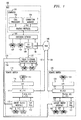
- FIG. 1 illustrates, in block diagram form, a system for implementing the invention
- FIG. 2 illustrates, in block diagram form, a remote switch
- FIG. 3 illustrates, in table form, information utilized by a system for implementing the invention
- FIGS. 4-6 illustrate the communications of control information for establishing a call between two telecommunication terminals connected on a remote switch
- FIG. 7 illustrates, in block diagram form, an universal network module.
- FIG. 1 illustrates a system for implementing the invention.
- Central business communication system (BCS) 100 provides control for all telecommunication terminals and trunks interconnected to switching network 105 and to remote switches 110 and 120 .
- BCS 100 is interconnected to remote switch 110 and remote switch 120 via wide area network (WAN) 140 .
- BCS 100 interconnects to WAN 140 via link 138 .
- remote switches 110 and 120 are interconnected to WAN 140 via links 137 and 136 , respectively.
- WAN 140 can be comprised of a variety of communication media including but not limited to the Internet or an Intranet of a corporation.
- BCS 100 , remote switch 110 , and remote switch 120 are interconnected to the public switching telephone network via trunks 133 , 134 , and 139 , respectively.
- Public switching telephone network 130 also provides direct service for telephones 131 through 132 .
- BCS 100 comprises computer 101 , switching network 105 , CO trunks 109 , telephones 107 - 108 and universal network module (UNM).
- Computer 101 provides overall control of BCS 100 by the execution of software modules 102 - 104 .
- BCS 100 may be the Definity Business Communication System manufactured by Avaya Inc.
- Switching network 105 and CO trunks 109 perform operations well known to those skilled in the art.
- UNM 106 provides the interface between BCS 100 and WAN 140 .
- UNM 106 performs the necessary conversion of both control and bearer information being transported on the IP protocol via WAN 140 to the protocol necessary so that this information can be communicated through switching network 105 either as control information to computer 101 or to telecommunication terminals such as telecommunication terminal 107 or trunks 109 .
- UNM 106 properly converts the protocol for control messages either being received or transmitted to computer 101 via switching network 105 .
- audio information being received from WAN 140 or being transmitted to it, it is necessary to do a conversion in the manner in which this information is encoded. Further details concerning the internal operations of UNM 106 are set forth in FIG. 7 .
- Remote switch 110 consists of elements 111 - 119 and remote switch 120 consists of elements 121 - 129 .
- router 111 is responsible for communicating both control and bearer information with WAN 140 to or from DSP pool 112 , circuit switch interface 113 , and LAN 114 via local bus 115 .
- router 111 provides overall control of elements 112 - 114 with respect to computer 101 .
- DSP pool 112 provides a plurality of DSP devices that are utilized for bearer channel conversion activities as well as performing other functions such as tone detection.
- Circuit switch interface 113 provides a mechanism for providing service for classical telecommunication terminals and trunks that are used by users at remote switch 110 .
- Circuit switch interface 113 together with router 111 allows computer 101 to control the classical telecommunication terminals attached to circuit switch interface 113 .
- These telecommunication terminals can be analog or digital telephones and a variety of central office trunks including analog or digital trunks.
- LAN 114 provides a local area network at the site of remote switch 110 which can be utilized by data terminals and IP telephones such as IP telephone 119 .
- Router 111 interconnects LAN 114 to WAN 140 and allows computer 101 to control the operation of IP telephones connected to LAN 114 .
- circuit switch interface 113 identifies each telecommunication terminal, i.e., terminal 116 to router 111 .
- Router 111 maintains internal Table 1 as illustrated in FIG. 3 that is explained later in greater detail for the telecommunication terminals.
- Router 111 then identifies each of the terminals to computer 101 .
- Computer 101 considers each of these terminals as an integral part of BCS 100 and establishes the proper identification within an internal table.
- telecommunication terminal 116 of remote switch 110 places a call to telecommunication terminal 107 of BCS 100 .
- the bearer channel continues to be maintained between telecommunication terminals 116 and 107 via switching network 105 , UNM 106 , WAN 140 , router 111 , and circuit switch interface 113 .
- circuit switch interface 113 communicates the call origination to router 111 which in turn transmits this to computer 101 of BCS 100 .
- Computer 101 controls switching network 105 so as to provide dial tone to telecommunication terminal 116 .
- router 111 utilizes a DSP from DSP pool 112 to detect these digits, is responsive to the detected digits to encode these digits and transmit them as digital control messages to computer 101 .
- Computer 101 then utilizing call processing module 102 determines that the call is being placed to telecommunication terminal 107 and transmits messages to switching network 105 to alert telecommunication terminal 107 .
- telecommunication terminal 107 responds to the alerting and answers the incoming call
- computer 101 completes a bearer channel through switching network 105 , UNM 106 , WAN 140 , router 111 and circuit interface 113 . This bearer channel remains established for the duration of the call.
- circuit switch interface 113 communicates the call origination to router 111 which in turn transmits this call origination to BCS 100 .
- Computer 101 controls switching network 105 so as to provide dial tone to telecommunication terminal 116 .
- router 111 utilizes a DSP from DSP pool 112 to detect these digits, is responsive to the detected digits to encode these digits and transmit them as digital control messages to computer 101 .
- Computer 101 then utilizing call processing module 102 determines that the call is being placed to telecommunication terminal 117 and request that alerting be provided to telecommunication terminal 117 .
- connection manager software module 104 is responsive to the IP addresses stored internally to transmit a shuffling message to both telecommunication terminals 116 and 117 utilizing the IP address for both messages as that of router 111 .
- Router 111 is responsive to the shuffling messages to determine that both telecommunication terminals are connected to circuit switch interface 113 . Router 111 then instructs circuit switch interface 113 to interconnect telecommunication terminals 116 and 117 utilizing the internal circuit switch network of circuit switch interface 113 .
- telecommunication terminal 116 originates a call to telecommunication terminal 127 that is connected to circuit switch interface 123 .
- Circuit switch interface 113 communicates the call origination from telecommunication terminal 116 to router 111 which in turn transmits this call origination to BCS 100 .
- Computer 101 controls switching network 105 so as to provide dial tone to telecommunication terminal 116 .
- router 111 utilizes a DSP from DSP pool 112 to detect these digits, is responsive to the detected digits to encode these digits and transmit them as digital control messages to computer 101 .
- Computer 101 then utilizing call processing module 102 determines that the call is being placed to telecommunication terminal 127 and request that alerting be provided to telecommunication terminal 127 via router 121 and circuit switch interface 123 .
- connection manager software module 104 is again responsive to the IP addresses stored internally to transmit a shuffling message to both telecommunication terminals 116 and 127 utilizing the IP address for router 111 and router 121 , respectively.
- Routers 111 and 121 are responsive to the shuffling messages to interconnect telecommunication terminals 116 and 117 utilizing the internal circuit switch networks of circuit switch interfaces 113 and 123 and WAN 140 .
- FIG. 2 illustrates in greater detail remote switch 110 .
- DSP pool 112 consists of DSPs 209 - 211 which are controlled by main CPU 201 via MPU bus 204 .
- Router 111 comprises main CPU 201 that provides overall control of remote switch 110 .
- Time slot interchange (TSI) 206 provides a mechanism for interexchanging time slots on local bus 115 and MPU bus 204 .
- TSI 206 can be utilized to interexchange time slots that are being received from telecommunication terminals 116 , 117 and trunk circuits 218 .
- This provides remote switch 110 with the capability of performing local circuit switching.
- Ethernet interface 202 interfaces local LAN 114 to bus 204 .
- WAN interface 203 interconnects bus 204 to WAN 140 .
- Bus 204 is the overall informational highway that is used to communicate both control and bearer information within router 111 .
- DSP pool 112 comprises DSPs 209 - 211 that are under control of main CPU 201 to perform the necessary coding and conversion tasks.
- Circuit switch interface 113 comprises elements 212 - 218 .
- Controller 212 provides overall control of circuit switch interface 113 .
- Bus interface 213 interfaces control bus 214 and TDM bus 216 with local bus 115 .
- Control bus 214 is utilized to communicate control information between line circuits 217 and trunk circuits 218 and controller 212 .
- TDM bus 216 is utilized to communicate digitally encoded speech or data samples with lines circuits 217 and trunk circuits 218 .
- Line circuits 217 are utilized to provide termination for telecommunication terminals; whereas, trunk circuits 218 terminate trunks with the public telephone switching network 130 .
- FIGS. 4-6 illustrate the flow of messages between computer 101 of BCS 100 , router 111 of remote switch 110 , and circuit switch interface 113 of remote switch 110 .
- Messages 401 - 416 of FIG. 4 illustrate the messages that are transmitted for each trunk and line circuit at initialization that is terminating terminals or trunks on circuit switch interface 113 .
- Router 111 maintains Table 1 of FIG.
- a telecommunication terminal When a telecommunication terminal becomes active, it transmits a registration request to router 111 identifying the endpoint ID number of the telecommunication terminal that has become active. Computer 101 and router 111 then exchange messages 402 through 406 to register router 111 on computer 101 . In response to message 401 , router 111 enters into Table 1 , FIG. 3, the endpoint identifier of the telecommunication terminal requesting registration and determines a TCP and RTP port numbers. To establish a logical channel for the telecommunication terminal, router transmits to computer 101 a H.225 Setup [Fast Start(endpoint capability set)] message which is message 407 .
- the format of the H.225 message means a Setup message with a Fast Start element with the endpoint capability set.
- router 111 also sends the TCP port number and a RTP port number to computer 111 .
- Computer 101 responds with an H.225 call proceeding message in message 408 and a H.225 INFO message (CCMS endpoint initialization) in message 409 .
- CCMS means a control channel message setup. When a CCMS message is transmitted from circuit switch interface 113 , it is stimulus message such as an off hook indication. When a CCMS message (as part of a H.225 INFO message) is transmitted by computer 101 , it is a control message such as turn the ringer in the terminal on.
- Router 111 transmits messages 411 to circuit switch interface 113 which are APIs messages initializing the CCMS endpoint initialization.
- Circuit switch interface 113 is responsive to messages 111 to confirm these initializations to router 111 in messages 412 .
- Router 111 communicates the CCMS endpoint initialization to computer 101 in message 413 .
- computer 101 transmits to router 111 a H.225 Connect [Fast Start (no CODEC)] message 414 to router 111 .
- router 111 closes the bearer capability on the channel and transmits message 416 to circuit switch interface 113 informing it that the registration has been successful. Note, that in transmitting CCMS information to computer 101 from router 111 , this information is placed in an INFO element of the H.225.
- the telecommunication terminal connected to circuit switch interface 113 After transmission of message 416 , the telecommunication terminal connected to circuit switch interface 113 , the telecommunication terminal is in the idle state but fully registered with computer 101 .
- Call processing module 102 of computer 101 views the telecommunication terminal as a digital telephone that is directly connected to BCS 100 .
- the sequence of messages 407416 is performed for all of the telecommunication terminals connected to circuit switch interface 113 .
- telecommunication terminal 116 When telecommunication terminal 116 originates a call, telecommunication terminal 116 transmits message 417 to router 111 . Note, that in this example telecommunication terminal 116 has endpoint number 1 and telecommunication terminal 117 has endpoint number 2 . At this point in the message flow diagrams, telecommunication terminal 117 has also been registered on computer 101 . In response to message 117 , router 111 transmits the CCMS off-hook signal to computer 101 utilizing an H.225 INFO message 418 . This message identifies telecommunication terminal 116 by its TCP port number. In response to message 418 , dial tone will be provided to telecommunication terminal 116 by a tone generator in switching network 105 of BCS 100 .
- message 501 of FIG. 5 which is an H.225 FAC message to router 111 .
- Message 501 includes the RTP number that has been chosen by computer 101 to refer to this bearer channel.
- message 501 defines the audio encoding protocol that will be utilized on this bearer channel. That information is utilized by router 111 to properly initiate a DSP from DSP pool 112 that will be used to encode the audio information being communicated with BCS 100 .
- the DSP assigned to the bearer channel converts the audio information being received over the IP channel to digitally encoded information that can be utilized by the line circuit controlling telecommunication terminal 116 . With respect to FIG. 2, this information is communicated from the assigned DSP in DSP pool 112 to the line circuit via MPU bus 204 , TSI 206 , local bus 115 , bus interface 213 , and TDM bus 216 .
- telecommunication terminal 116 starts to dial DTMF tones (signals 518 ), these tones are routed to the assigned DSP in DSP pool 112 .
- the assigned DSP detects each DTMF digit and transmits this DTMF digit to main CPU 201 via control bus 214 , controller 212 and MPU bus 204 .
- Main CPU 201 then transmits each of these converted DTMF digits to computer 101 as illustrated by messages 502 and 503 .
- Computer 101 is responsive to the dialed telephone number of telecommunication terminal 117 to transmit message 504 that is a H.225 INFO (endpoint 2 CCMS ringer-on) message.
- message 504 that is a H.225 INFO (endpoint 2 CCMS ringer-on) message.
- router 111 transmits message 506 to circuit switch interface 113 instructing that ringing be applied to telecommunication terminal 117 .
- Router 111 identifies the telecommunication terminal for which message 501 is intended by the RTP number that computer 101 includes in message 501 .
- this same type of identification is done but for telecommunication terminal 117 .
- the IP address is that for router 111 .
- IP address There is only one IP address for router 111 ; hence, for all of the telecommunication terminals and trunks attached to circuit switch interface 113 .
- computer 101 After transmitting message 504 , computer 101 transmits message 507 that is an H.225 FAC [Fast Start endpoint] message that establishes a bearer channel to switching network 105 from telecommunication terminal 117 . Note, that this is not actually used if it is possible to perform shuffling between the telecommunication endpoints.
- an endpoint 2 off-hook message (message 508 ) is. transmitted from circuit switch interface 113 to router 111 .
- router 111 transmits to computer 101 message 509 that is an H.225 INFO (endpoint 2 CCMS off-hook) message.
- computer 101 transmits message 511 that is an H.225 INFO (endpoint 2 CCMS ringer-off) message to router 111 to turn off the ringing to telecommunication terminal 117 .
- message 512 that instructs circuit switch interface 113 to turn off the ringing for telecommunication terminal 117 .
- endpoint 1 and endpoint 2 are IP endpoints that can be shuffled which means that these endpoints can directly transmit to each other without having to go through switching network 105 .
- Computer 101 transmits messages 513 and 516 to remove these two IP bearer channels to switching network 105 from remote switch 110 .
- Messages 513 and 516 are H.225 FAC Fast Start messages to null the CODEC's.
- To actually interconnect the two IP endpoints computer 101 transmits message 514 that is an H.225 FAC [Fast Start (endpoint 1 audio to endpoint 2 )] message.
- the IP address to which message 514 and a similar message 517 are set is the IP address of router 111 .
- Router 111 utilizes the RTP number contained in the messages to determine that these messages are actually endpoints connected to circuit switch interface 113 by examining Table 1 of FIG. 3 . Hence, in response to messages 514 and 517 , router 111 establishes a digital channel between the lines circuits controlling telecommunication terminals 116 and 117 via TDM bus 216 , bus interface 213 , local bus 115 , and TSI 206 of FIG. 2 .
- the software applications of computer 101 are unaware of the physical locations of these telecommunication terminals in fact this procedure works equally well if the telecommunication terminals are each on a different remote switch.
- the messages illustrated in FIG. 6 illustrate how the established call is removed.
- Telecommunication terminal 116 goes on-hook, and circuit switch interface 113 transmits an endpoint 1 CCMS on-hook message 601 to router 111 .
- router 111 encodes the message into an INFO message and transmits this message as message 602 that is an H.225 INFO (endpoint 1 CCMS o-hook) message to computer 101 .
- computer 101 transmits messages 603 and 604 that are H.225 FAC [Fast Start (endpoint null CODEC)] messages.
- FIG. 7 shows in greater detail universal network module 106 of FIG. 1 .
- TDM bus 707 which is an integral part of switching network 105 .
- All units such as CO trunks 109 interface to switching network 105 via bearer bus 704 and control bus 706 .
- bearer bus 704 interfaces to switching network 105 via bearer bus 704 and control bus 706 .
- telephone sets 107 - 108 have an intermediate line interface circuit to TDM bus 707 .
- Control bus 706 communicates control information; whereas, bearer bus 704 communicates bearer information in a time division protocol.
- Bearer bus interface 702 communicates information from bearer bus 704 and router 703 .
- Bearer bus interface 702 performs the necessary translations in protocols between bearer bus 704 and router 703 .
- control bus interface 701 communicates control information from control bus 706 and router 703 .
- router 703 communicates designated control information to WAN 140 via link 138 and utilizes other control information to control its own internal operations and to transmit control information to computer 101 via control bus 706 and control bus interface 703 .
- Control bus 701 communicates with control bus 706 via bilateral link 708 .
- Bearer bus interface 702 communicates with bearer bus 704 via bilateral link 709 .
Abstract
Description
Claims (12)
Priority Applications (1)
| Application Number | Priority Date | Filing Date | Title |
|---|---|---|---|
| US09/718,909 US6674853B1 (en) | 2000-11-22 | 2000-11-22 | Integration of remote access and service |
Applications Claiming Priority (1)
| Application Number | Priority Date | Filing Date | Title |
|---|---|---|---|
| US09/718,909 US6674853B1 (en) | 2000-11-22 | 2000-11-22 | Integration of remote access and service |
Publications (1)
| Publication Number | Publication Date |
|---|---|
| US6674853B1 true US6674853B1 (en) | 2004-01-06 |
Family
ID=29737193
Family Applications (1)
| Application Number | Title | Priority Date | Filing Date |
|---|---|---|---|
| US09/718,909 Expired - Lifetime US6674853B1 (en) | 2000-11-22 | 2000-11-22 | Integration of remote access and service |
Country Status (1)
| Country | Link |
|---|---|
| US (1) | US6674853B1 (en) |
Cited By (2)
| Publication number | Priority date | Publication date | Assignee | Title |
|---|---|---|---|---|
| US20040073729A1 (en) * | 2001-03-15 | 2004-04-15 | Oliver Kniffler | Data bus configuration having a data bus which can be operated in multiplex mode, and method for operating the configuration |
| US20100282951A1 (en) * | 2009-05-08 | 2010-11-11 | Avago Technologies Ecbu (Singapore) Pte. Ltd. | Metal Shield and Housing for Optical Proximity Sensor with Increased Resistance to Mechanical Deformation |
Citations (11)
| Publication number | Priority date | Publication date | Assignee | Title |
|---|---|---|---|---|
| US5159594A (en) * | 1990-12-31 | 1992-10-27 | At&T Bell Laboratories | Transparent communication of control information through a switching network |
| US5416834A (en) * | 1991-12-30 | 1995-05-16 | At&T Corp. | Redirection of calls by a communication terminal |
| US5764639A (en) * | 1995-11-15 | 1998-06-09 | Staples; Leven E. | System and method for providing a remote user with a virtual presence to an office |
| US5867568A (en) * | 1996-08-22 | 1999-02-02 | Lucent Technologies Inc. | Coverage of redirected calls |
| US6023470A (en) * | 1996-05-17 | 2000-02-08 | Lee; Warren S. | Point of presence (POP) for digital facsimile network with virtual POPs used to communicate with other networks |
| US6028917A (en) * | 1997-04-04 | 2000-02-22 | International Business Machines Corporation | Access to extended telephone services via the internet |
| US6084892A (en) * | 1997-03-11 | 2000-07-04 | Bell Atlantic Networks Services, Inc. | Public IP transport network |
| US6115460A (en) * | 1997-06-30 | 2000-09-05 | Lucent Technologies Inc. | Call redirection system |
| US6301339B1 (en) * | 1995-11-15 | 2001-10-09 | Data Race, Inc. | System and method for providing a remote user with a virtual presence to an office |
| US6377571B1 (en) * | 1998-04-23 | 2002-04-23 | 3Com Corporation | Virtual modem for dialout clients in virtual private network |
| US6438585B2 (en) * | 1998-05-29 | 2002-08-20 | Research In Motion Limited | System and method for redirecting message attachments between a host system and a mobile data communication device |
-
2000
- 2000-11-22 US US09/718,909 patent/US6674853B1/en not_active Expired - Lifetime
Patent Citations (11)
| Publication number | Priority date | Publication date | Assignee | Title |
|---|---|---|---|---|
| US5159594A (en) * | 1990-12-31 | 1992-10-27 | At&T Bell Laboratories | Transparent communication of control information through a switching network |
| US5416834A (en) * | 1991-12-30 | 1995-05-16 | At&T Corp. | Redirection of calls by a communication terminal |
| US5764639A (en) * | 1995-11-15 | 1998-06-09 | Staples; Leven E. | System and method for providing a remote user with a virtual presence to an office |
| US6301339B1 (en) * | 1995-11-15 | 2001-10-09 | Data Race, Inc. | System and method for providing a remote user with a virtual presence to an office |
| US6023470A (en) * | 1996-05-17 | 2000-02-08 | Lee; Warren S. | Point of presence (POP) for digital facsimile network with virtual POPs used to communicate with other networks |
| US5867568A (en) * | 1996-08-22 | 1999-02-02 | Lucent Technologies Inc. | Coverage of redirected calls |
| US6084892A (en) * | 1997-03-11 | 2000-07-04 | Bell Atlantic Networks Services, Inc. | Public IP transport network |
| US6028917A (en) * | 1997-04-04 | 2000-02-22 | International Business Machines Corporation | Access to extended telephone services via the internet |
| US6115460A (en) * | 1997-06-30 | 2000-09-05 | Lucent Technologies Inc. | Call redirection system |
| US6377571B1 (en) * | 1998-04-23 | 2002-04-23 | 3Com Corporation | Virtual modem for dialout clients in virtual private network |
| US6438585B2 (en) * | 1998-05-29 | 2002-08-20 | Research In Motion Limited | System and method for redirecting message attachments between a host system and a mobile data communication device |
Cited By (3)
| Publication number | Priority date | Publication date | Assignee | Title |
|---|---|---|---|---|
| US20040073729A1 (en) * | 2001-03-15 | 2004-04-15 | Oliver Kniffler | Data bus configuration having a data bus which can be operated in multiplex mode, and method for operating the configuration |
| US7599383B2 (en) * | 2001-03-15 | 2009-10-06 | Infineon Technologies Ag | Data bus configuration having a data bus which can be operated in multiplex mode, and method for operating the configuration |
| US20100282951A1 (en) * | 2009-05-08 | 2010-11-11 | Avago Technologies Ecbu (Singapore) Pte. Ltd. | Metal Shield and Housing for Optical Proximity Sensor with Increased Resistance to Mechanical Deformation |
Similar Documents
| Publication | Publication Date | Title |
|---|---|---|
| US5602846A (en) | Simultaneous voice and data call establishment using a simultaneous voice and data modem pool and private branch exchange facilities | |
| US6636508B1 (en) | Network resource conservation system | |
| US5699413A (en) | Voice data modem, voice data method and voice data modem system | |
| KR100372036B1 (en) | Dual phone | |
| EP0898838B1 (en) | A modem with ip support | |
| US7197030B2 (en) | Processing device network | |
| US6810033B2 (en) | Transmission system using packet switched network | |
| RU2273108C2 (en) | Providing system and terminal operation mode in at least two communication modes | |
| US6275573B1 (en) | System and method for secured network access | |
| KR100876760B1 (en) | Method for converting call processing in internet protocol telephony exchange system | |
| GB2381995A (en) | Internet Protocol telephony exchange system | |
| GB2315190A (en) | An internet telephony gateway for providing an interface between a circuit switched and packet switched network | |
| KR100450964B1 (en) | Method for servicing of station group in internet protocol telephony exchange system | |
| US7016338B2 (en) | Methods, system and gateway for accessing features of equipment connected to a PSTN | |
| KR100474912B1 (en) | Dual internet protocol phone, communicating method using the same | |
| US6674853B1 (en) | Integration of remote access and service | |
| EP1699219B1 (en) | A method for providing features to the user of a telephone, a central unit and a telecommunication system therefor | |
| KR100400924B1 (en) | Apparatus and method for providing multi user service using call ID box | |
| EP1014667A2 (en) | Data network call handling method | |
| JPH11285037A (en) | Terminal adaptor | |
| KR20020025130A (en) | Switching System that Converts PBX(Private Branch Exchange)'s One Port into The Multi-port | |
| KR20040041908A (en) | Method Realizing Addition Function In Voice over Internet Protocol | |
| JPH06245241A (en) | Private network control system | |
| EP0864235A2 (en) | Apparatus and method in support of completing two calls using analog interface to telephone network | |
| JPH0451755A (en) | Isdn line control system |
Legal Events
| Date | Code | Title | Description |
|---|---|---|---|
| AS | Assignment |
Owner name: AVAYA INC., NEW JERSEY Free format text: ASSIGNMENT OF ASSIGNORS INTEREST;ASSIGNORS:EZELL, JOEL;HELTON, JOHN S.;PETTY, NORMAN W.;AND OTHERS;REEL/FRAME:011909/0629;SIGNING DATES FROM 20010425 TO 20010606 |
|
| AS | Assignment |
Owner name: AVAYA TECHNOLOGIES CORP., NEW JERSEY Free format text: ASSIGNMENT OF ASSIGNORS INTEREST;ASSIGNOR:AVAYA INC.;REEL/FRAME:012702/0533 Effective date: 20010921 |
|
| AS | Assignment |
Owner name: BANK OF NEW YORK, THE, NEW YORK Free format text: SECURITY AGREEMENT;ASSIGNOR:AVAYA TECHNOLOGY CORP.;REEL/FRAME:012759/0141 Effective date: 20020405 Owner name: BANK OF NEW YORK, THE,NEW YORK Free format text: SECURITY AGREEMENT;ASSIGNOR:AVAYA TECHNOLOGY CORP.;REEL/FRAME:012759/0141 Effective date: 20020405 |
|
| STCF | Information on status: patent grant |
Free format text: PATENTED CASE |
|
| FPAY | Fee payment |
Year of fee payment: 4 |
|
| AS | Assignment |
Owner name: CITIBANK, N.A., AS ADMINISTRATIVE AGENT, NEW YORK Free format text: SECURITY AGREEMENT;ASSIGNORS:AVAYA, INC.;AVAYA TECHNOLOGY LLC;OCTEL COMMUNICATIONS LLC;AND OTHERS;REEL/FRAME:020156/0149 Effective date: 20071026 Owner name: CITIBANK, N.A., AS ADMINISTRATIVE AGENT,NEW YORK Free format text: SECURITY AGREEMENT;ASSIGNORS:AVAYA, INC.;AVAYA TECHNOLOGY LLC;OCTEL COMMUNICATIONS LLC;AND OTHERS;REEL/FRAME:020156/0149 Effective date: 20071026 |
|
| AS | Assignment |
Owner name: CITICORP USA, INC., AS ADMINISTRATIVE AGENT, NEW Y Free format text: SECURITY AGREEMENT;ASSIGNORS:AVAYA, INC.;AVAYA TECHNOLOGY LLC;OCTEL COMMUNICATIONS LLC;AND OTHERS;REEL/FRAME:020166/0705 Effective date: 20071026 Owner name: CITICORP USA, INC., AS ADMINISTRATIVE AGENT, NEW YORK Free format text: SECURITY AGREEMENT;ASSIGNORS:AVAYA, INC.;AVAYA TECHNOLOGY LLC;OCTEL COMMUNICATIONS LLC;AND OTHERS;REEL/FRAME:020166/0705 Effective date: 20071026 Owner name: CITICORP USA, INC., AS ADMINISTRATIVE AGENT,NEW YO Free format text: SECURITY AGREEMENT;ASSIGNORS:AVAYA, INC.;AVAYA TECHNOLOGY LLC;OCTEL COMMUNICATIONS LLC;AND OTHERS;REEL/FRAME:020166/0705 Effective date: 20071026 |
|
| AS | Assignment |
Owner name: AVAYA INC, NEW JERSEY Free format text: REASSIGNMENT;ASSIGNOR:AVAYA TECHNOLOGY LLC;REEL/FRAME:021158/0310 Effective date: 20080625 |
|
| AS | Assignment |
Owner name: AVAYA TECHNOLOGY LLC, NEW JERSEY Free format text: CONVERSION FROM CORP TO LLC;ASSIGNOR:AVAYA TECHNOLOGY CORP.;REEL/FRAME:022071/0420 Effective date: 20051004 |
|
| AS | Assignment |
Owner name: BANK OF NEW YORK MELLON TRUST, NA, AS NOTES COLLATERAL AGENT, THE, PENNSYLVANIA Free format text: SECURITY AGREEMENT;ASSIGNOR:AVAYA INC., A DELAWARE CORPORATION;REEL/FRAME:025863/0535 Effective date: 20110211 Owner name: BANK OF NEW YORK MELLON TRUST, NA, AS NOTES COLLAT Free format text: SECURITY AGREEMENT;ASSIGNOR:AVAYA INC., A DELAWARE CORPORATION;REEL/FRAME:025863/0535 Effective date: 20110211 |
|
| FPAY | Fee payment |
Year of fee payment: 8 |
|
| AS | Assignment |
Owner name: BANK OF NEW YORK MELLON TRUST COMPANY, N.A., THE, PENNSYLVANIA Free format text: SECURITY AGREEMENT;ASSIGNOR:AVAYA, INC.;REEL/FRAME:030083/0639 Effective date: 20130307 Owner name: BANK OF NEW YORK MELLON TRUST COMPANY, N.A., THE, Free format text: SECURITY AGREEMENT;ASSIGNOR:AVAYA, INC.;REEL/FRAME:030083/0639 Effective date: 20130307 |
|
| FPAY | Fee payment |
Year of fee payment: 12 |
|
| AS | Assignment |
Owner name: CITIBANK, N.A., AS ADMINISTRATIVE AGENT, NEW YORK Free format text: SECURITY INTEREST;ASSIGNORS:AVAYA INC.;AVAYA INTEGRATED CABINET SOLUTIONS INC.;OCTEL COMMUNICATIONS CORPORATION;AND OTHERS;REEL/FRAME:041576/0001 Effective date: 20170124 |
|
| AS | Assignment |
Owner name: OCTEL COMMUNICATIONS LLC (FORMERLY KNOWN AS OCTEL COMMUNICATIONS CORPORATION), CALIFORNIA Free format text: BANKRUPTCY COURT ORDER RELEASING ALL LIENS INCLUDING THE SECURITY INTEREST RECORDED AT REEL/FRAME 041576/0001;ASSIGNOR:CITIBANK, N.A.;REEL/FRAME:044893/0531 Effective date: 20171128 Owner name: AVAYA INTEGRATED CABINET SOLUTIONS INC., CALIFORNIA Free format text: BANKRUPTCY COURT ORDER RELEASING ALL LIENS INCLUDING THE SECURITY INTEREST RECORDED AT REEL/FRAME 041576/0001;ASSIGNOR:CITIBANK, N.A.;REEL/FRAME:044893/0531 Effective date: 20171128 Owner name: AVAYA INC. (FORMERLY KNOWN AS AVAYA TECHNOLOGY COR Free format text: BANKRUPTCY COURT ORDER RELEASING ALL LIENS INCLUDING THE SECURITY INTEREST RECORDED AT REEL/FRAME 012759/0141;ASSIGNOR:THE BANK OF NEW YORK;REEL/FRAME:044891/0439 Effective date: 20171128 Owner name: AVAYA INC., CALIFORNIA Free format text: BANKRUPTCY COURT ORDER RELEASING ALL LIENS INCLUDING THE SECURITY INTEREST RECORDED AT REEL/FRAME 025863/0535;ASSIGNOR:THE BANK OF NEW YORK MELLON TRUST, NA;REEL/FRAME:044892/0001 Effective date: 20171128 Owner name: VPNET TECHNOLOGIES, INC., CALIFORNIA Free format text: BANKRUPTCY COURT ORDER RELEASING ALL LIENS INCLUDING THE SECURITY INTEREST RECORDED AT REEL/FRAME 041576/0001;ASSIGNOR:CITIBANK, N.A.;REEL/FRAME:044893/0531 Effective date: 20171128 Owner name: OCTEL COMMUNICATIONS LLC (FORMERLY KNOWN AS OCTEL Free format text: BANKRUPTCY COURT ORDER RELEASING ALL LIENS INCLUDING THE SECURITY INTEREST RECORDED AT REEL/FRAME 041576/0001;ASSIGNOR:CITIBANK, N.A.;REEL/FRAME:044893/0531 Effective date: 20171128 Owner name: AVAYA INTEGRATED CABINET SOLUTIONS INC., CALIFORNI Free format text: BANKRUPTCY COURT ORDER RELEASING ALL LIENS INCLUDING THE SECURITY INTEREST RECORDED AT REEL/FRAME 041576/0001;ASSIGNOR:CITIBANK, N.A.;REEL/FRAME:044893/0531 Effective date: 20171128 Owner name: AVAYA INC., CALIFORNIA Free format text: BANKRUPTCY COURT ORDER RELEASING ALL LIENS INCLUDING THE SECURITY INTEREST RECORDED AT REEL/FRAME 041576/0001;ASSIGNOR:CITIBANK, N.A.;REEL/FRAME:044893/0531 Effective date: 20171128 Owner name: AVAYA INC., CALIFORNIA Free format text: BANKRUPTCY COURT ORDER RELEASING ALL LIENS INCLUDING THE SECURITY INTEREST RECORDED AT REEL/FRAME 030083/0639;ASSIGNOR:THE BANK OF NEW YORK MELLON TRUST COMPANY, N.A.;REEL/FRAME:045012/0666 Effective date: 20171128 |
|
| AS | Assignment |
Owner name: OCTEL COMMUNICATIONS LLC, CALIFORNIA Free format text: RELEASE BY SECURED PARTY;ASSIGNOR:CITICORP USA, INC.;REEL/FRAME:045032/0213 Effective date: 20171215 Owner name: AVAYA TECHNOLOGY, LLC, NEW JERSEY Free format text: RELEASE BY SECURED PARTY;ASSIGNOR:CITICORP USA, INC.;REEL/FRAME:045032/0213 Effective date: 20171215 Owner name: VPNET TECHNOLOGIES, INC., NEW JERSEY Free format text: RELEASE BY SECURED PARTY;ASSIGNOR:CITICORP USA, INC.;REEL/FRAME:045032/0213 Effective date: 20171215 Owner name: AVAYA, INC., CALIFORNIA Free format text: RELEASE BY SECURED PARTY;ASSIGNOR:CITICORP USA, INC.;REEL/FRAME:045032/0213 Effective date: 20171215 Owner name: SIERRA HOLDINGS CORP., NEW JERSEY Free format text: RELEASE BY SECURED PARTY;ASSIGNOR:CITICORP USA, INC.;REEL/FRAME:045032/0213 Effective date: 20171215 |
|
| AS | Assignment |
Owner name: GOLDMAN SACHS BANK USA, AS COLLATERAL AGENT, NEW YORK Free format text: SECURITY INTEREST;ASSIGNORS:AVAYA INC.;AVAYA INTEGRATED CABINET SOLUTIONS LLC;OCTEL COMMUNICATIONS LLC;AND OTHERS;REEL/FRAME:045034/0001 Effective date: 20171215 Owner name: GOLDMAN SACHS BANK USA, AS COLLATERAL AGENT, NEW Y Free format text: SECURITY INTEREST;ASSIGNORS:AVAYA INC.;AVAYA INTEGRATED CABINET SOLUTIONS LLC;OCTEL COMMUNICATIONS LLC;AND OTHERS;REEL/FRAME:045034/0001 Effective date: 20171215 |
|
| AS | Assignment |
Owner name: CITIBANK, N.A., AS COLLATERAL AGENT, NEW YORK Free format text: SECURITY INTEREST;ASSIGNORS:AVAYA INC.;AVAYA INTEGRATED CABINET SOLUTIONS LLC;OCTEL COMMUNICATIONS LLC;AND OTHERS;REEL/FRAME:045124/0026 Effective date: 20171215 |
|
| AS | Assignment |
Owner name: WILMINGTON TRUST, NATIONAL ASSOCIATION, MINNESOTA Free format text: SECURITY INTEREST;ASSIGNORS:AVAYA INC.;AVAYA MANAGEMENT L.P.;INTELLISIST, INC.;AND OTHERS;REEL/FRAME:053955/0436 Effective date: 20200925 |
|
| AS | Assignment |
Owner name: AVAYA INTEGRATED CABINET SOLUTIONS LLC, NEW JERSEY Free format text: RELEASE OF SECURITY INTEREST IN PATENTS AT REEL 45124/FRAME 0026;ASSIGNOR:CITIBANK, N.A., AS COLLATERAL AGENT;REEL/FRAME:063457/0001 Effective date: 20230403 Owner name: AVAYA MANAGEMENT L.P., NEW JERSEY Free format text: RELEASE OF SECURITY INTEREST IN PATENTS AT REEL 45124/FRAME 0026;ASSIGNOR:CITIBANK, N.A., AS COLLATERAL AGENT;REEL/FRAME:063457/0001 Effective date: 20230403 Owner name: AVAYA INC., NEW JERSEY Free format text: RELEASE OF SECURITY INTEREST IN PATENTS AT REEL 45124/FRAME 0026;ASSIGNOR:CITIBANK, N.A., AS COLLATERAL AGENT;REEL/FRAME:063457/0001 Effective date: 20230403 Owner name: AVAYA HOLDINGS CORP., NEW JERSEY Free format text: RELEASE OF SECURITY INTEREST IN PATENTS AT REEL 45124/FRAME 0026;ASSIGNOR:CITIBANK, N.A., AS COLLATERAL AGENT;REEL/FRAME:063457/0001 Effective date: 20230403 |
|
| AS | Assignment |
Owner name: AVAYA MANAGEMENT L.P., NEW JERSEY Free format text: RELEASE OF SECURITY INTEREST IN PATENTS (REEL/FRAME 045034/0001);ASSIGNOR:GOLDMAN SACHS BANK USA., AS COLLATERAL AGENT;REEL/FRAME:063779/0622 Effective date: 20230501 Owner name: CAAS TECHNOLOGIES, LLC, NEW JERSEY Free format text: RELEASE OF SECURITY INTEREST IN PATENTS (REEL/FRAME 045034/0001);ASSIGNOR:GOLDMAN SACHS BANK USA., AS COLLATERAL AGENT;REEL/FRAME:063779/0622 Effective date: 20230501 Owner name: HYPERQUALITY II, LLC, NEW JERSEY Free format text: RELEASE OF SECURITY INTEREST IN PATENTS (REEL/FRAME 045034/0001);ASSIGNOR:GOLDMAN SACHS BANK USA., AS COLLATERAL AGENT;REEL/FRAME:063779/0622 Effective date: 20230501 Owner name: HYPERQUALITY, INC., NEW JERSEY Free format text: RELEASE OF SECURITY INTEREST IN PATENTS (REEL/FRAME 045034/0001);ASSIGNOR:GOLDMAN SACHS BANK USA., AS COLLATERAL AGENT;REEL/FRAME:063779/0622 Effective date: 20230501 Owner name: ZANG, INC. (FORMER NAME OF AVAYA CLOUD INC.), NEW JERSEY Free format text: RELEASE OF SECURITY INTEREST IN PATENTS (REEL/FRAME 045034/0001);ASSIGNOR:GOLDMAN SACHS BANK USA., AS COLLATERAL AGENT;REEL/FRAME:063779/0622 Effective date: 20230501 Owner name: VPNET TECHNOLOGIES, INC., NEW JERSEY Free format text: RELEASE OF SECURITY INTEREST IN PATENTS (REEL/FRAME 045034/0001);ASSIGNOR:GOLDMAN SACHS BANK USA., AS COLLATERAL AGENT;REEL/FRAME:063779/0622 Effective date: 20230501 Owner name: OCTEL COMMUNICATIONS LLC, NEW JERSEY Free format text: RELEASE OF SECURITY INTEREST IN PATENTS (REEL/FRAME 045034/0001);ASSIGNOR:GOLDMAN SACHS BANK USA., AS COLLATERAL AGENT;REEL/FRAME:063779/0622 Effective date: 20230501 Owner name: AVAYA INTEGRATED CABINET SOLUTIONS LLC, NEW JERSEY Free format text: RELEASE OF SECURITY INTEREST IN PATENTS (REEL/FRAME 045034/0001);ASSIGNOR:GOLDMAN SACHS BANK USA., AS COLLATERAL AGENT;REEL/FRAME:063779/0622 Effective date: 20230501 Owner name: INTELLISIST, INC., NEW JERSEY Free format text: RELEASE OF SECURITY INTEREST IN PATENTS (REEL/FRAME 045034/0001);ASSIGNOR:GOLDMAN SACHS BANK USA., AS COLLATERAL AGENT;REEL/FRAME:063779/0622 Effective date: 20230501 Owner name: AVAYA INC., NEW JERSEY Free format text: RELEASE OF SECURITY INTEREST IN PATENTS (REEL/FRAME 045034/0001);ASSIGNOR:GOLDMAN SACHS BANK USA., AS COLLATERAL AGENT;REEL/FRAME:063779/0622 Effective date: 20230501 Owner name: AVAYA INTEGRATED CABINET SOLUTIONS LLC, NEW JERSEY Free format text: RELEASE OF SECURITY INTEREST IN PATENTS (REEL/FRAME 53955/0436);ASSIGNOR:WILMINGTON TRUST, NATIONAL ASSOCIATION, AS NOTES COLLATERAL AGENT;REEL/FRAME:063705/0023 Effective date: 20230501 Owner name: INTELLISIST, INC., NEW JERSEY Free format text: RELEASE OF SECURITY INTEREST IN PATENTS (REEL/FRAME 53955/0436);ASSIGNOR:WILMINGTON TRUST, NATIONAL ASSOCIATION, AS NOTES COLLATERAL AGENT;REEL/FRAME:063705/0023 Effective date: 20230501 Owner name: AVAYA INC., NEW JERSEY Free format text: RELEASE OF SECURITY INTEREST IN PATENTS (REEL/FRAME 53955/0436);ASSIGNOR:WILMINGTON TRUST, NATIONAL ASSOCIATION, AS NOTES COLLATERAL AGENT;REEL/FRAME:063705/0023 Effective date: 20230501 Owner name: AVAYA MANAGEMENT L.P., NEW JERSEY Free format text: RELEASE OF SECURITY INTEREST IN PATENTS (REEL/FRAME 53955/0436);ASSIGNOR:WILMINGTON TRUST, NATIONAL ASSOCIATION, AS NOTES COLLATERAL AGENT;REEL/FRAME:063705/0023 Effective date: 20230501 |