US6672402B2 - Combined fastenerless motor end cap and output device mounting - Google Patents
Combined fastenerless motor end cap and output device mounting Download PDFInfo
- Publication number
- US6672402B2 US6672402B2 US10/036,011 US3601101A US6672402B2 US 6672402 B2 US6672402 B2 US 6672402B2 US 3601101 A US3601101 A US 3601101A US 6672402 B2 US6672402 B2 US 6672402B2
- Authority
- US
- United States
- Prior art keywords
- output device
- end plate
- motor
- motor end
- device housing
- Prior art date
- Legal status (The legal status is an assumption and is not a legal conclusion. Google has not performed a legal analysis and makes no representation as to the accuracy of the status listed.)
- Expired - Fee Related, expires
Links
Images


Classifications
-
- B—PERFORMING OPERATIONS; TRANSPORTING
- B25—HAND TOOLS; PORTABLE POWER-DRIVEN TOOLS; MANIPULATORS
- B25F—COMBINATION OR MULTI-PURPOSE TOOLS NOT OTHERWISE PROVIDED FOR; DETAILS OR COMPONENTS OF PORTABLE POWER-DRIVEN TOOLS NOT PARTICULARLY RELATED TO THE OPERATIONS PERFORMED AND NOT OTHERWISE PROVIDED FOR
- B25F5/00—Details or components of portable power-driven tools not particularly related to the operations performed and not otherwise provided for
- B25F5/02—Construction of casings, bodies or handles
Definitions
- the present invention relates generally to a motor end cap, and more particularly, to a motor end cap having a simplified output device mounting.
- power tools are designed having a motor that rotationally drives an output such as a drill bit, screwdriver, or other rotational device.
- the output rotational speed and torque is obtained by providing a output device device, such as a planetary gear set, between the motor and the output.
- the output device includes a circular housing that holds the planetary gear set.
- the motor itself, is attached to one axial end of the output device housing with the motor output shaft pinion extending into the output device housing to drive the planetary gear set.
- the output of the planetary gear set then rotationally drives the output of the power tool.
- the motor and transmission form one unit.
- the one piece motor and output device are assembled before the exterior tool housing is applied.
- the one piece unit is positioned inside and assembled to the inner shell of the power tool.
- a plurality of screws are typically fastened through ears on the end cap of the motor and apertures on the outer periphery of the output device housing.
- the screws are sometimes fastened through apertures in the end of the motor instead of through ears. While this use of screws does maintain the motor and transmission as one unit, positioning plural screws and apertures through the output device and motor end require additional materials and labor, thereby increasing the overall cost of the system.
- the screws and apertures are mounted outside the motor and output device and resultantly take up more radial space. As such, the overall one piece unit requires more radial space due to the addition of the screws and apertures.
- the present invention was developed in light of these and other drawbacks.
- the present invention provides a motor and output device assembly that includes a motor end plate with an output device attachment area and a output device housing with a motor end plate attachment area.
- the output device attachment area detachably connects to the output device housing to form a one unit output device assembly that can be easily detached in the future and does not require additional fasteners.
- a power tool that utilizes a motor end plate having an output device attachment area and a output device housing having a motor end plate attachment area.
- the output device attachment area detachably connects to the motor end plate attachment area.
- a method of attaching a motor end plate to a output device housing includes placing the motor end plate against an axial end of the output device housing such that locking tabs of the output device attachment area ride within slot portions on the output device housing. The motor end plate is then rotated to drive the locking tabs along the slot portions in the output device housing to detachably adjoin the motor end plate to the output device housing.
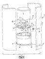
- FIG. 1 is a cross-sectional view of a motor mounted to an output device according to the present invention
- FIG. 2 is an exploded perspective view of a motor and output device according the present invention
- FIG. 3A is an exploded perspective view of the attachment between a motor and an output device housing according to a first embodiment of the present invention
- FIG. 3B is an exploded perspective view of the attachment between a motor and an output device housing according to a second embodiment of the present invention
- FIG. 3C is an exploded perspective view of the attachment between a motor and an output device housing according to a third embodiment of the present invention.
- FIG. 4A is a perspective view of a motor end plate and output device housing assembled according to the first embodiment of the present invention
- FIG. 4B is a motor end plate and output device housing assembled according to the second embodiment of the present invention.
- FIG. 4C is a motor end plate and output device housing assembled according to the third embodiment of the present invention.
- FIG. 5 is a side view of a motor end cap according to the first embodiment of the present invention.
- FIG. 6 is an exploded perspective view of a motor and output device according the present invention.
- a power tool 10 having a casing 12 , motor 14 , motor end plate 16 and an output device 18 .
- the output device 18 generally includes a output device housing 20 that contains a planetary gear set to modify the input torque and rotational velocity from the motor to an output device, such as a screwdriver or other attachment head.
- Output shaft 30 (in FIG. 2) has a pinion 32 that acts as a sun gear for the planetary gear set of the output device 18 .
- rotational energy transmitted from output shaft 30 is transmitted to planetary gears in the output device housing 20 and ultimately to the output device.
- Motor 14 is positioned within casing 12 .
- Motor end plate 16 acts to connect motor 14 to output device 18 .
- Tabs 34 extend into casing 12 for anchoring to maintain motor 14 and output device 18 in a fixed rotational position in the casing 12 . It is noted that the tabs 34 could also extend from casing 12 into the end cap 16 .
- motor housing tabs 38 (only two of four motor housing tabs 38 shown in FIG. 2) engage cutout sections 40 of motor end plate 16 . Once engaged, motor tabs 38 are bent over to lockingly adjoin motor end plate 16 to motor 14 .
- the motor end plate 16 can be formed, molded or extruded as one unit with the remainder of the motor in a can shape, and the motor and end plate can be one piece as shown in FIG. 6 . However, the motor end plate still occupies the bottom portion of the motor.
- FIGS. 2, 3 A and 4 A the attachment of motor end plate 16 to output device housing 20 is described in greater detail.
- motor end plate 16 is shown having an output device attachment area 42 .
- Output device attachment area 42 includes a base portion 44 disposed on a downward side of motor end plate 16 , and a locking tab 46 extending radially outward from a center of motor end plate 16 .
- locking bump 48 On an upper side of locking tab 46 is locking bump 48 .
- output device attachment area 42 is positioned proximate tab 34 .
- another output device attachment area 42 can be positioned approximately 180 degrees opposite the one shown and described in FIG. 3 A. It is noted, however, that only one tab may be used as shown in the figure. In addition, three or more tabs may also be used, and each of the tabs can be positioned at any radial location and need not be positioned 180 degrees apart.
- output device housing 20 contains a motor end plate attachment area 50 .
- Motor end plate attachment area 50 includes a downward slot portion 52 disposed in an axial direction on an axial face of output device housing 20 .
- Circumferential slot portion 54 runs in a direction of the circumference of output device housing 20 and passes completely through the housing.
- Detent 56 is located at a predetermined position along circumferential slot portion 54 .
- Locking tabs 46 are positioned on opposite sides of motor end plate 16 , about 180 degrees from one another.
- the locking tabs can be formed by any known process, and can also be formed by stamping the tabs out of the relatively flat motor end plate.
- locking tabs 46 are moved downward into downward slot portion 52 until the face of the end cap abuts with the face of the output device housing.
- motor end plate 16 is rotated about its axis in a direction to move locking bump 48 toward detent 56 .
- output device housing 20 can be rotated with respect to motor end plate 16 , instead of the motor end plate being rotated.
- each output device attachment area 42 is shown with a respective locking tab 46 and locking bump 48 .
- Output shaft 30 positioned through aperture 36 of motor end plate 16 , enables pinion 32 to mesh with the planetary gear set inside output device housing 20 .
- the motor 14 and output device housing 20 are positioned inside casing 12 .
- each of the tabs 34 and 35 sit inside respective apertures 33 and 37 . This acts to axially and radially support the motor and output device with casing 12 , thereby helping to alleviate the force applied to motor end plate attachment area and the output device attachment area.
- only one tab and aperture need be used, and the two shown in the figure are preferred.
- output device attachment area 42 includes a locking tab 46 a that has a locking bump 48 a at the radial most outward position from the axial center of motor end plate 16 .
- output device housing 20 has a downward slot portion 52 with a width to accommodate the width of locking tab 46 a .
- Circumferential slot portion 52 is provided with detent 56 a .
- Detent 56 a is a vertical rod extending from a bottom surface of circumferential slot portion 54 to a top surface of circumferential slot portion 54 .
- motor end plate 16 is positioned on the upper face of output device housing 20 to allow locking tab 46 a to drop down into downward slot portion 52 .
- motor end plate 16 is rotated in a direction to move locking bump 48 a toward detent 56 a .
- a forced rotation of motor end plate 16 is required to move locking bumps 48 a to a position past detents 56 a .
- Reverse rotation in the opposite direction is required to release motor end plate 16 . This rotation is also resisted by the interference between locking bumps 48 a and detents 56 a.
- motor end plate 16 has apertures 60 and is proximate tabs 34 .
- Motor end plate attachment area 50 of output device housing 20 has barbed tabs 62 .
- Barbed tabs 62 extend axially parallel to output device housing 20 and are attached to an inner surface of the output device. Accordingly, when motor end plate 16 is positioned downward onto an upper surface of output device housing 20 , barbed tabs 62 interlocks with apertures 60 to maintain motor end plate 16 in a locked position with output device housing 20 .
- the widths of locking bumps 48 and 48 a and downward slot portions 52 can be different on opposite sides of the housing. More specifically, one slot portion 52 and corresponding locking bump can be very wide while the opposite slot portion and locking bump can be narrow. Thus, each locking bump only fits its respective slot portion.
- motor end plate 16 can be attached to output device housing 20 in one direction and not the other. In other words, motor end plate 16 is unable to be rotated 180 degrees and then attached to output device housing 20 . This has significant manufacturing advantages. Specifically, if the motor and output device are required to be aligned in one angular direction, such a design will prohibit misalignment or improper assembly. Likewise, in the embodiment of FIG.
- barb tabs 62 and apertures 60 can have different characteristics to ensure that motor end plate 16 is attached only one way to output device housing 20 .
- motor end plate 16 can be detached from output device housing 20 very easily by simply rotating motor end plate 16 in a direction out of respective detents 56 and 56 a .
- barb tab 62 on each 180 degree side is simply moved radially outward or likewise radially inward to allow walls of aperture 60 to slide thereover for removal of motor end plate 16 . This has advantages for servicing the interior components of output device housing 20 and motor 14 after assembly.
- the motor end plate 16 attaches to the output device by using a quick connect/disconnect attachment mechanism. This allows the motor end plate 16 to detachably connect to the output device housing 20 by moving the motor endplate with respect to the output device. Specifically, in the embodiments of FIGS. 3A and 3B, the motor endplate is pushed down and rotated to lock the two elements together. And, the reverse procedure is used to unlock. Likewise, in the embodiment of FIG. 3C, the motor endplate is pressed down until the barbed tabs 62 lock with apertures 60 .
- the present invention operates by use of the quick connect/disconnect attachment by mere movement of the two elements with respect to one another. Further, it is noted that other quick connect/disconnect arrangements can be used that are not included in this description.
Abstract
Description
Claims (15)
Priority Applications (10)
| Application Number | Priority Date | Filing Date | Title |
|---|---|---|---|
| US10/036,011 US6672402B2 (en) | 2001-12-27 | 2001-12-27 | Combined fastenerless motor end cap and output device mounting |
| DE60232636T DE60232636D1 (en) | 2001-12-27 | 2002-12-13 | Combined fastener-free connection of a motor end cover and a power take-off device |
| EP02027876A EP1323501B1 (en) | 2001-12-27 | 2002-12-13 | Combined fastenerless motor end cap and output device mounting |
| AT02027876T ATE433838T1 (en) | 2001-12-27 | 2002-12-13 | COMBINED FASTENER-FREE CONNECTION OF AN ENGINE END COVER AND AN OUTPUT DEVICE |
| JP2003557758A JP4382491B2 (en) | 2001-12-27 | 2002-12-18 | Motor end caps and output device mounts connected without using fixtures |
| AU2002357344A AU2002357344A1 (en) | 2001-12-27 | 2002-12-18 | Combined fastenerless motor end cap and output device mounting |
| PCT/US2002/040709 WO2003057415A1 (en) | 2001-12-27 | 2002-12-18 | Combined fastenerless motor end cap and output device mounting |
| MXPA04006318A MXPA04006318A (en) | 2001-12-27 | 2002-12-18 | Combined fastenerless motor end cap and output device mounting. |
| TW091137014A TWI281433B (en) | 2001-12-27 | 2002-12-23 | Motor and output device assembly, power tool, and method for attaching a motor to an output device |
| CN02159399.XA CN1280973C (en) | 2001-12-27 | 2002-12-27 | Motor top cover and output device combined mounting structure without fastener |
Applications Claiming Priority (1)
| Application Number | Priority Date | Filing Date | Title |
|---|---|---|---|
| US10/036,011 US6672402B2 (en) | 2001-12-27 | 2001-12-27 | Combined fastenerless motor end cap and output device mounting |
Publications (2)
| Publication Number | Publication Date |
|---|---|
| US20030121676A1 US20030121676A1 (en) | 2003-07-03 |
| US6672402B2 true US6672402B2 (en) | 2004-01-06 |
Family
ID=21886089
Family Applications (1)
| Application Number | Title | Priority Date | Filing Date |
|---|---|---|---|
| US10/036,011 Expired - Fee Related US6672402B2 (en) | 2001-12-27 | 2001-12-27 | Combined fastenerless motor end cap and output device mounting |
Country Status (10)
| Country | Link |
|---|---|
| US (1) | US6672402B2 (en) |
| EP (1) | EP1323501B1 (en) |
| JP (1) | JP4382491B2 (en) |
| CN (1) | CN1280973C (en) |
| AT (1) | ATE433838T1 (en) |
| AU (1) | AU2002357344A1 (en) |
| DE (1) | DE60232636D1 (en) |
| MX (1) | MXPA04006318A (en) |
| TW (1) | TWI281433B (en) |
| WO (1) | WO2003057415A1 (en) |
Cited By (16)
| Publication number | Priority date | Publication date | Assignee | Title |
|---|---|---|---|---|
| US20040216907A1 (en) * | 2002-09-20 | 2004-11-04 | Happ Kenneth C. | Power tool with air seal and vibration dampener |
| US20060201690A1 (en) * | 2005-03-09 | 2006-09-14 | Siegfried Fehrle | Electric hand-held power tool |
| US20090194306A1 (en) * | 2008-02-04 | 2009-08-06 | Ingersoll Rand Company | Power tool housing support structures |
| US7649337B2 (en) | 2005-05-17 | 2010-01-19 | Milwaukee Electric Tool Corporation | Power tool including a fuel gauge and method of operating the same |
| US7814816B2 (en) | 2005-05-17 | 2010-10-19 | Milwaukee Electric Tool Corporation | Power tool, battery, charger and method of operating the same |
| US20110037352A1 (en) * | 2009-08-14 | 2011-02-17 | Lin Engineering | Motor end cap positioning element for maintaining rotor-stator concentricity |
| US20120090182A1 (en) * | 2009-04-20 | 2012-04-19 | Aesculap Suhl Gmbh | Animal shearing machine |
| US8283841B2 (en) | 2010-06-23 | 2012-10-09 | Lin Engineering | Motor end cap with interference fit |
| WO2012135283A3 (en) * | 2011-03-31 | 2012-12-27 | Ingersoll-Rand Company | Twist lock gear case for power tools |
| US20140231116A1 (en) * | 2011-05-27 | 2014-08-21 | Norbar Torque Tools Ltd. | Torque tool with synchronous reluctance motor |
| US9044850B2 (en) | 2011-07-27 | 2015-06-02 | Ingersoll-Rand Company | Twist lock gear case for power tools |
| US10971966B2 (en) | 2018-05-14 | 2021-04-06 | Black & Decker Inc. | Power tool with partition assembly between transmission and motor |
| US11247322B2 (en) * | 2016-12-23 | 2022-02-15 | Hilti Aktiengesellschaft | Tool device—with module attachments |
| US11333237B2 (en) | 2014-12-15 | 2022-05-17 | Robert Bosch Gmbh | Handheld tool device |
| US11667025B2 (en) * | 2016-12-23 | 2023-06-06 | Hilti Aktiengesellschaft | Tool device |
| US11813729B2 (en) | 2018-05-14 | 2023-11-14 | Black & Decker Inc. | Power tool with partition assembly between transmission and motor |
Families Citing this family (18)
| Publication number | Priority date | Publication date | Assignee | Title |
|---|---|---|---|---|
| DE102004047606A1 (en) * | 2004-09-30 | 2006-04-06 | Hilti Ag | Drill and / or chisel hammer |
| EP1674213B1 (en) | 2004-12-23 | 2008-10-01 | BLACK & DECKER INC. | Power tool cooling |
| EP1674215B1 (en) * | 2004-12-23 | 2016-09-28 | Black & Decker Inc. | Hammer drill |
| JP4643298B2 (en) | 2005-02-14 | 2011-03-02 | 株式会社マキタ | Impact tool |
| FR2896284B1 (en) † | 2006-01-18 | 2008-04-11 | Valeo Systemes Thermiques | DEVICE FOR FIXING AN ACTUATOR AND A HOUSING, IN PARTICULAR FOR A MOTOR VEHICLE |
| DE102007024387A1 (en) * | 2007-05-25 | 2008-11-27 | Robert Bosch Gmbh | electrical appliance |
| EP2082848B1 (en) * | 2008-01-24 | 2013-04-10 | Robert Bosch Gmbh | An electrical device having a battery pack with an easy attachment and release mechanism |
| DE102009054640A1 (en) * | 2009-12-15 | 2011-06-16 | Robert Bosch Gmbh | Hand tool |
| CH703098A2 (en) * | 2010-05-03 | 2011-11-15 | Peter A Mueller | Linkable drive. |
| DE102010043184A1 (en) * | 2010-10-29 | 2012-05-03 | Robert Bosch Gmbh | Machine tool braking device |
| DE102010043178A1 (en) * | 2010-10-29 | 2012-05-03 | Robert Bosch Gmbh | Machine tool braking device |
| US9796073B2 (en) * | 2012-08-27 | 2017-10-24 | Ingersoll-Rand Company | Housing for power tool |
| US9221156B2 (en) * | 2013-05-15 | 2015-12-29 | Snap-On Incorporated | Motorized hand tool apparatus and assembly method |
| DE102015017296B3 (en) * | 2015-08-14 | 2021-10-07 | Franka Emika Gmbh | Robotic system |
| US10632589B2 (en) * | 2016-08-29 | 2020-04-28 | Black & Decker Inc. | Power tool |
| WO2019001654A1 (en) * | 2017-06-28 | 2019-01-03 | Linak A/S | Linear actuator |
| EP3792005B1 (en) * | 2019-09-11 | 2023-06-07 | Robert Bosch GmbH | Machine tool with a transmission flange |
| US20220088753A1 (en) * | 2020-09-22 | 2022-03-24 | Snap-On Incorporated | Tool and motor anti-rotation |
Citations (24)
| Publication number | Priority date | Publication date | Assignee | Title |
|---|---|---|---|---|
| US3724237A (en) | 1971-06-07 | 1973-04-03 | Black & Decker Mfg Co | Attachment coupling for power tool |
| US4093096A (en) | 1977-05-19 | 1978-06-06 | Societe Anonyme Dite: Arts Et Techniques Nouvelles | Removable stopper for a screw-neck bottle |
| US4103511A (en) | 1976-10-04 | 1978-08-01 | Firma Kress Elektrik Gmbh & Co. | Connecting arrangement for a machine tool |
| US4435166A (en) | 1981-06-05 | 1984-03-06 | Edi Bondioli | Guard made up of sectional units for cardan shafts |
| US4482073A (en) | 1982-11-18 | 1984-11-13 | M.B.F. Plastiques | System for retaining a cap with respect to the neck of a recipient |
| US4597453A (en) * | 1985-02-08 | 1986-07-01 | Cooper Industries, Inc. | Drive unit with self-aligning gearing system |
| US4625134A (en) * | 1985-03-25 | 1986-11-25 | Emhart Industries, Inc. | Means for mounting a gear train and motor |
| EP0408987A2 (en) | 1989-07-15 | 1991-01-23 | Kress-elektrik GmbH + Co. Elektromotorenfabrik | Electric tool |
| US5033552A (en) | 1990-07-24 | 1991-07-23 | Hu Cheng Te | Multi-function electric tool |
| DE4126118A1 (en) | 1991-08-07 | 1993-02-11 | Swf Auto Electric Gmbh | Stop connection between motor pot and gear housing - works with vehicle windscreen wiper drive with spring element fixed to gear housing and having at least two spring-elastic extensions |
| US5251776A (en) | 1991-08-12 | 1993-10-12 | H. William Morgan, Jr. | Pressure vessel |
| DE4235962A1 (en) | 1992-10-24 | 1994-05-05 | Licentia Gmbh | Electric motor, in particular a moisture-proof closed commutator motor for driving an axially flange-mounted hydraulic pump |
| US5347673A (en) | 1992-10-01 | 1994-09-20 | Black & Decker Inc. | Quick change pad assembly for orbital polisher |
| DE4422492A1 (en) | 1993-07-19 | 1995-01-26 | Teves Gmbh Alfred | Motor having an epicyclic gear |
| US5409256A (en) | 1994-01-04 | 1995-04-25 | General Motors Corporation | Driver-side air bag module assembly |
| US5624000A (en) * | 1994-07-26 | 1997-04-29 | Black & Decker, Inc. | Power tool with modular drive system and method of assembly of modular drive system |
| US5637104A (en) | 1995-06-15 | 1997-06-10 | Abbott Laboratories | Locking cap for the pour spout of a suction container |
| US5722574A (en) | 1996-11-14 | 1998-03-03 | Ogio International, Inc. | Container and retaining apparatus |
| DE19634502A1 (en) | 1996-08-26 | 1998-03-12 | Interelectric Ag | Electric motor with attached additional element |
| EP0847127A1 (en) | 1996-11-06 | 1998-06-10 | SAIA-Burgess Electronics AG | Electric drive |
| DE19729988C1 (en) | 1997-07-12 | 1998-08-13 | Buehler Gmbh Nachf Geb | Positive-locking connection between plastic gear case section and adaptor plate of electric motor |
| DE29820723U1 (en) | 1998-11-19 | 1999-02-25 | Mobiletron Electronics Co | Drill structure for high speeds |
| US6039126A (en) * | 1998-05-15 | 2000-03-21 | Hsieh; An-Fu | Multi-usage electric tool with angle-changeable grip |
| US6170579B1 (en) * | 1997-08-30 | 2001-01-09 | Black & Decker Inc. | Power tool having interchangeable tool head |
Family Cites Families (1)
| Publication number | Priority date | Publication date | Assignee | Title |
|---|---|---|---|---|
| US5714815A (en) * | 1995-09-05 | 1998-02-03 | Mattel, Inc. | Motor mount assembly |
-
2001
- 2001-12-27 US US10/036,011 patent/US6672402B2/en not_active Expired - Fee Related
-
2002
- 2002-12-13 EP EP02027876A patent/EP1323501B1/en not_active Expired - Lifetime
- 2002-12-13 DE DE60232636T patent/DE60232636D1/en not_active Expired - Lifetime
- 2002-12-13 AT AT02027876T patent/ATE433838T1/en not_active IP Right Cessation
- 2002-12-18 WO PCT/US2002/040709 patent/WO2003057415A1/en active Application Filing
- 2002-12-18 MX MXPA04006318A patent/MXPA04006318A/en active IP Right Grant
- 2002-12-18 AU AU2002357344A patent/AU2002357344A1/en not_active Abandoned
- 2002-12-18 JP JP2003557758A patent/JP4382491B2/en not_active Expired - Fee Related
- 2002-12-23 TW TW091137014A patent/TWI281433B/en not_active IP Right Cessation
- 2002-12-27 CN CN02159399.XA patent/CN1280973C/en not_active Expired - Fee Related
Patent Citations (25)
| Publication number | Priority date | Publication date | Assignee | Title |
|---|---|---|---|---|
| US3724237A (en) | 1971-06-07 | 1973-04-03 | Black & Decker Mfg Co | Attachment coupling for power tool |
| US4103511A (en) | 1976-10-04 | 1978-08-01 | Firma Kress Elektrik Gmbh & Co. | Connecting arrangement for a machine tool |
| US4093096A (en) | 1977-05-19 | 1978-06-06 | Societe Anonyme Dite: Arts Et Techniques Nouvelles | Removable stopper for a screw-neck bottle |
| US4435166A (en) | 1981-06-05 | 1984-03-06 | Edi Bondioli | Guard made up of sectional units for cardan shafts |
| US4482073A (en) | 1982-11-18 | 1984-11-13 | M.B.F. Plastiques | System for retaining a cap with respect to the neck of a recipient |
| US4597453A (en) * | 1985-02-08 | 1986-07-01 | Cooper Industries, Inc. | Drive unit with self-aligning gearing system |
| US4625134A (en) * | 1985-03-25 | 1986-11-25 | Emhart Industries, Inc. | Means for mounting a gear train and motor |
| EP0408987A2 (en) | 1989-07-15 | 1991-01-23 | Kress-elektrik GmbH + Co. Elektromotorenfabrik | Electric tool |
| US5033552A (en) | 1990-07-24 | 1991-07-23 | Hu Cheng Te | Multi-function electric tool |
| DE4126118A1 (en) | 1991-08-07 | 1993-02-11 | Swf Auto Electric Gmbh | Stop connection between motor pot and gear housing - works with vehicle windscreen wiper drive with spring element fixed to gear housing and having at least two spring-elastic extensions |
| US5251776A (en) | 1991-08-12 | 1993-10-12 | H. William Morgan, Jr. | Pressure vessel |
| US5347673A (en) | 1992-10-01 | 1994-09-20 | Black & Decker Inc. | Quick change pad assembly for orbital polisher |
| US5576586A (en) * | 1992-10-24 | 1996-11-19 | Licentia Patent-Verwaltungs-Gmbh | Electric motor, particularly a commutator motor sealed to be liquid-tight, for driving an axially flange-mounted hydraulic pump |
| DE4235962A1 (en) | 1992-10-24 | 1994-05-05 | Licentia Gmbh | Electric motor, in particular a moisture-proof closed commutator motor for driving an axially flange-mounted hydraulic pump |
| DE4422492A1 (en) | 1993-07-19 | 1995-01-26 | Teves Gmbh Alfred | Motor having an epicyclic gear |
| US5409256A (en) | 1994-01-04 | 1995-04-25 | General Motors Corporation | Driver-side air bag module assembly |
| US5624000A (en) * | 1994-07-26 | 1997-04-29 | Black & Decker, Inc. | Power tool with modular drive system and method of assembly of modular drive system |
| US5637104A (en) | 1995-06-15 | 1997-06-10 | Abbott Laboratories | Locking cap for the pour spout of a suction container |
| DE19634502A1 (en) | 1996-08-26 | 1998-03-12 | Interelectric Ag | Electric motor with attached additional element |
| EP0847127A1 (en) | 1996-11-06 | 1998-06-10 | SAIA-Burgess Electronics AG | Electric drive |
| US5722574A (en) | 1996-11-14 | 1998-03-03 | Ogio International, Inc. | Container and retaining apparatus |
| DE19729988C1 (en) | 1997-07-12 | 1998-08-13 | Buehler Gmbh Nachf Geb | Positive-locking connection between plastic gear case section and adaptor plate of electric motor |
| US6170579B1 (en) * | 1997-08-30 | 2001-01-09 | Black & Decker Inc. | Power tool having interchangeable tool head |
| US6039126A (en) * | 1998-05-15 | 2000-03-21 | Hsieh; An-Fu | Multi-usage electric tool with angle-changeable grip |
| DE29820723U1 (en) | 1998-11-19 | 1999-02-25 | Mobiletron Electronics Co | Drill structure for high speeds |
Cited By (25)
| Publication number | Priority date | Publication date | Assignee | Title |
|---|---|---|---|---|
| US7152695B2 (en) * | 2002-09-20 | 2006-12-26 | Snap-On Incorporated | Power tool with air seal and vibration dampener |
| US20040216907A1 (en) * | 2002-09-20 | 2004-11-04 | Happ Kenneth C. | Power tool with air seal and vibration dampener |
| US20060201690A1 (en) * | 2005-03-09 | 2006-09-14 | Siegfried Fehrle | Electric hand-held power tool |
| US7987918B2 (en) * | 2005-03-09 | 2011-08-02 | Robert Bosch Gmbh | Electric hand-held power tool |
| US7932695B2 (en) | 2005-05-17 | 2011-04-26 | Milwaukee Electric Tool Corporation | Power tool, battery, charger and method of operating the same |
| US7649337B2 (en) | 2005-05-17 | 2010-01-19 | Milwaukee Electric Tool Corporation | Power tool including a fuel gauge and method of operating the same |
| US7814816B2 (en) | 2005-05-17 | 2010-10-19 | Milwaukee Electric Tool Corporation | Power tool, battery, charger and method of operating the same |
| US20090194306A1 (en) * | 2008-02-04 | 2009-08-06 | Ingersoll Rand Company | Power tool housing support structures |
| US7896103B2 (en) * | 2008-02-04 | 2011-03-01 | Ingersoll Rand Company | Power tool housing support structures |
| US20120090182A1 (en) * | 2009-04-20 | 2012-04-19 | Aesculap Suhl Gmbh | Animal shearing machine |
| US8769824B2 (en) * | 2009-04-20 | 2014-07-08 | Aesculap Suhl Gmbh | Animal shearing machine |
| US20110037352A1 (en) * | 2009-08-14 | 2011-02-17 | Lin Engineering | Motor end cap positioning element for maintaining rotor-stator concentricity |
| US8278803B2 (en) | 2009-08-14 | 2012-10-02 | Lin Engineering | Motor end cap positioning element for maintaining rotor-stator concentricity |
| US8283841B2 (en) | 2010-06-23 | 2012-10-09 | Lin Engineering | Motor end cap with interference fit |
| CN103702802A (en) * | 2011-03-31 | 2014-04-02 | 英格索尔-兰德公司 | Twist lock gear case for power tools |
| WO2012135283A3 (en) * | 2011-03-31 | 2012-12-27 | Ingersoll-Rand Company | Twist lock gear case for power tools |
| US20140231116A1 (en) * | 2011-05-27 | 2014-08-21 | Norbar Torque Tools Ltd. | Torque tool with synchronous reluctance motor |
| US9676086B2 (en) * | 2011-05-27 | 2017-06-13 | Norbar Torque Tools Ltd. | Torque tool with synchronous reluctance motor |
| US9044850B2 (en) | 2011-07-27 | 2015-06-02 | Ingersoll-Rand Company | Twist lock gear case for power tools |
| US11333237B2 (en) | 2014-12-15 | 2022-05-17 | Robert Bosch Gmbh | Handheld tool device |
| US11247322B2 (en) * | 2016-12-23 | 2022-02-15 | Hilti Aktiengesellschaft | Tool device—with module attachments |
| US11667025B2 (en) * | 2016-12-23 | 2023-06-06 | Hilti Aktiengesellschaft | Tool device |
| US10971966B2 (en) | 2018-05-14 | 2021-04-06 | Black & Decker Inc. | Power tool with partition assembly between transmission and motor |
| US11817757B2 (en) | 2018-05-14 | 2023-11-14 | Black & Decker Inc. | Power tool with partition assembly between transmission and motor |
| US11813729B2 (en) | 2018-05-14 | 2023-11-14 | Black & Decker Inc. | Power tool with partition assembly between transmission and motor |
Also Published As
| Publication number | Publication date |
|---|---|
| WO2003057415A1 (en) | 2003-07-17 |
| TW200301725A (en) | 2003-07-16 |
| AU2002357344A1 (en) | 2003-07-24 |
| JP2005514891A (en) | 2005-05-19 |
| US20030121676A1 (en) | 2003-07-03 |
| CN1428919A (en) | 2003-07-09 |
| JP4382491B2 (en) | 2009-12-16 |
| ATE433838T1 (en) | 2009-07-15 |
| DE60232636D1 (en) | 2009-07-30 |
| TWI281433B (en) | 2007-05-21 |
| EP1323501A3 (en) | 2007-09-19 |
| MXPA04006318A (en) | 2004-10-04 |
| CN1280973C (en) | 2006-10-18 |
| EP1323501A2 (en) | 2003-07-02 |
| EP1323501B1 (en) | 2009-06-17 |
Similar Documents
| Publication | Publication Date | Title |
|---|---|---|
| US6672402B2 (en) | Combined fastenerless motor end cap and output device mounting | |
| JP6452178B2 (en) | Servo motor and robot | |
| US20130047762A1 (en) | Switchable gear drive for a handheld power tool | |
| EP3081833B1 (en) | Oil seal cap and eccentric oscillation-type gear device including the same | |
| DE112013006302T5 (en) | Power transmission unit for vehicle | |
| JP7020805B2 (en) | Mounting structure and gear motor equipped with it | |
| US10641379B2 (en) | Electronic parking lock actuator for automatic transmission of vehicle | |
| US8281690B2 (en) | Indexable offset adaptor | |
| US8613353B2 (en) | Parking lock device for transmission | |
| JP4207028B2 (en) | Internal combustion engine starting rotational force transmission mechanism and internal combustion engine forced rotational drive test method | |
| US6592489B2 (en) | Transmission equipped with planetary gear mechanism and planetary gear mechanism | |
| US6364777B1 (en) | Torque-transmitting connecting arrangement | |
| EP1253336B1 (en) | Spline connection for limited access space and method of assembly and disassembly | |
| US6452296B1 (en) | Motor device and transmission mechanism | |
| JPH10110800A (en) | Ball screw type linear actuator | |
| JP2019060425A (en) | Motor with speed reducer | |
| JP2582510Y2 (en) | Automatic transmission parking mechanism | |
| EP3489546B1 (en) | Planetary gear reduction device for super high speed reduction | |
| CN112555385A (en) | Gear box assembly and worm shaft assembly thereof | |
| JP3991578B2 (en) | Method of assembling special differential device and jig used in the method | |
| JP5880814B2 (en) | Sliding spline shaft device and manufacturing method thereof | |
| US8083473B2 (en) | Interface for a stamped stator and a one-way clutch | |
| CN111156304A (en) | Differential gear | |
| KR102380595B1 (en) | Multi-axis drill head | |
| CN214465946U (en) | Gearbox, actuator and device |
Legal Events
| Date | Code | Title | Description |
|---|---|---|---|
| AS | Assignment |
Owner name: BLACK & DECKER CORPORATION, THE, MARYLAND Free format text: ASSIGNMENT OF ASSIGNORS INTEREST;ASSIGNORS:ORTT, EARL M.;DOYLE, MICHAEL C.;MARCINKOWSKI, ROBERT J.;REEL/FRAME:012426/0142;SIGNING DATES FROM 20011220 TO 20011221 |
|
| AS | Assignment |
Owner name: BLACK & DECKER INC., DELAWARE Free format text: CORRECTIVE ASSIGNMENT TO CORRECT THE ASSIGNEE'S NAME, PREVIOUSLY RECORDED AT REEL 012426 FRAME 0142;ASSIGNORS:ORTT, EARL M.;DOYLE, MICHAEL C.;MARCINKOWSKI, ROBERT J.;REEL/FRAME:013033/0590 Effective date: 20020617 |
|
| FEPP | Fee payment procedure |
Free format text: PAYOR NUMBER ASSIGNED (ORIGINAL EVENT CODE: ASPN); ENTITY STATUS OF PATENT OWNER: LARGE ENTITY |
|
| FPAY | Fee payment |
Year of fee payment: 4 |
|
| FPAY | Fee payment |
Year of fee payment: 8 |
|
| REMI | Maintenance fee reminder mailed | ||
| LAPS | Lapse for failure to pay maintenance fees | ||
| STCH | Information on status: patent discontinuation |
Free format text: PATENT EXPIRED DUE TO NONPAYMENT OF MAINTENANCE FEES UNDER 37 CFR 1.362 |
|
| FP | Lapsed due to failure to pay maintenance fee |
Effective date: 20160106 |