US6661973B1 - Optical transmission systems, apparatuses, and methods - Google Patents
Optical transmission systems, apparatuses, and methods Download PDFInfo
- Publication number
- US6661973B1 US6661973B1 US09/326,748 US32674899A US6661973B1 US 6661973 B1 US6661973 B1 US 6661973B1 US 32674899 A US32674899 A US 32674899A US 6661973 B1 US6661973 B1 US 6661973B1
- Authority
- US
- United States
- Prior art keywords
- optical
- signal
- information
- wavelengths
- signal wavelengths
- Prior art date
- Legal status (The legal status is an assumption and is not a legal conclusion. Google has not performed a legal analysis and makes no representation as to the accuracy of the status listed.)
- Expired - Lifetime
Links
Images


Classifications
-
- H—ELECTRICITY
- H04—ELECTRIC COMMUNICATION TECHNIQUE
- H04J—MULTIPLEX COMMUNICATION
- H04J14/00—Optical multiplex systems
- H04J14/02—Wavelength-division multiplex systems
-
- H—ELECTRICITY
- H04—ELECTRIC COMMUNICATION TECHNIQUE
- H04J—MULTIPLEX COMMUNICATION
- H04J14/00—Optical multiplex systems
- H04J14/02—Wavelength-division multiplex systems
- H04J14/0298—Wavelength-division multiplex systems with sub-carrier multiplexing [SCM]
-
- H—ELECTRICITY
- H04—ELECTRIC COMMUNICATION TECHNIQUE
- H04J—MULTIPLEX COMMUNICATION
- H04J14/00—Optical multiplex systems
- H04J14/02—Wavelength-division multiplex systems
- H04J14/0201—Add-and-drop multiplexing
Definitions
- the present invention is directed generally to communication networks and systems. More particularly, the invention relates to optical WDM systems and optical components, such as add/drop devices, employing multiple wavelength detection and processing.
- Optical communication systems transport information by generating optical signals corresponding to the information and transmitting the optical signals through optical transmission fiber.
- Information in various formats, such audio, video, data, or any other formats can be optical transported through many different networks, such as local and long distance telephone, cable television, LAN, WAN, and MAN systems, as well as other communication networks.
- Optical systems can be operated over a broad range of frequencies/wavelengths, each of which is suitable for high speed data transmission and is generally unaffected by conditions external to the fiber, such as electrical interference. Also, information can be carried using multiple optical wavelengths that are combined using wavelength division multiplexing (“WDM”) techniques into one optical signal and transmitted through the optical systems. As such, optical fiber transmission systems have the potential to provide significantly higher transmission capacity at a substantially lower cost than electrical transmission systems.
- WDM wavelength division multiplexing
- optical transmission systems are not free from various forms of degradation that limit the performance of the systems.
- optical fiber is not a perfect transmitter of electromagnetic radiation in the optical spectrum.
- the intensity of an optical signal is attenuated as it travels through the fiber, due to diffraction from fiber material imperfections and other degradation mechanisms.
- optical noise from signal attenuation and optical components in the system will accumulate and propagate in the fiber, and chromatic dispersion and nonlinear signal interactions will degrade the quality of the signal.
- optical systems are generally not operated in the identical manner or using a common set of wavelengths that would facilitate optical transmission across interfaces between optical systems.
- optical signal attenuation namely: 1) optical signal attenuation, 2) optical signal degradation, and 3) optical system interconnectivity.
- the regeneration of optical signals can be performed either optically or electrically.
- optical signals had to be electrically regenerated by converting the optical signal into an electrical signal, while the signal intensity was sufficiently high and the optical noise sufficiently low that the signal could be detected.
- the electrical signal would then be amplified, further processed, if desired, converted back to an optical signal and transmitted through the next span of fiber.
- Electrical regenerators of this type are commonly referred to as 3 R (reshape, retime, regenerate) repeaters.
- the general configuration of a 3 R repeater includes a number of optical receivers electrically connected to a corresponding number of optical transmitters.
- the number of receiver/transmitter pairs corresponding to the number of wavelengths used in the optical system.
- the optical receivers generally include optical to electrical converters, such as a photodiodes, configured to receive an information carrying wavelength from the optical fiber and provide a corresponding information carrying electrical signal. Electrical amplification, and other processing, such as retiming, reshaping, electrical add/drop multiplexing and demultiplexing, etc. are performed on the electrical signal as necessary.
- the optical transmitter converts the regenerated electrical signal into an optical signal and transmits the optical signal into the next optical fiber span.
- the electrical to optical conversion at the transmitter is typically performed by either directly or externally modulating an optical signal laser with the regenerated electrical signal.
- Electrical regenerators are well known in the art, for example, see U.S. Pat. Nos. 5,504,609; 5,267,073; 4,663,596; 4,549,314; 4,313,224; 4,307,469; 4,295,225; 4,234,970; 4,075,474; 4,019,048; 4,002,896; and, 3,943,358.
- optical systems operate in the 1300 nm range to minimize the degradation of the optical signal due to chromatic dispersion that occurs in the optical fibers. While other optical systems are operated in the 1550 nm range, which minimizes the optical signal attenuation in the fiber.
- Electrical regeneration of optical signals to interface with another optical systems is generally performed as part of the electrical regeneration performed to compensate for signal attenuation and/or degradation.
- the optical links can be established to minimize the number of regeneration points required between the signal origin and destination.
- a difficulty with optical amplified systems is that optical noise accumulates in the fiber and chromatic dispersion and non-linear interactions degrade the signal quality as the signal propagates in the fiber.
- the increasing noise levels and signal degradation produce a corresponding increase in the bit error rate of the system.
- optical amplifiers have greatly reduced the need for electrical regeneration, optical systems still require electrical regeneration to eliminate accumulated optical noise and maintain signal quality, as well as interface with other optical systems.
- a further advantage of optical amplifiers over electrical regenerators is that a plurality of wavelengths can be optically amplified at one time with only minimal additional expense.
- the primary additional expense is the cost of providing optical energy, i.e., pump power, to the optical amplifier, which increases with the number of wavelengths and/or the gain of the amplifier.
- optical amplifiers to optically regenerate optical signals over a range of wavelengths has dramatically decreased the number of electrical regenerators required in optical systems.
- the reduction in electrical regeneration requirement has dramatically increased the commercial viability of WDM systems as a cost effective means of adding capacity to optical systems.
- the number of wavelengths used in a WDM system is limited to specific wavelength range in which the optical amplifiers can amplify optical signals.
- the number of channels is also limited by the spacing of the wavelength channels in the WDM system.
- the channel spacing in optical systems is limited by a number of factors, one of which is the modulation technique used in the optical transmitter.
- the modulation technique used in the optical transmitter For example, direct modulation of the laser is the most cost effective technique for imparting information onto a carrier wavelength, because it avoids the need and the expense of an external modulator for each wavelength in the system.
- direct modulation result in excessive linewidth broadening and wavelength instability which limits the wavelength spacing in WDM systems.
- the wavelength spacing was also limited, in part, by the ability to effectively separate wavelengths from the WDM signal at the receiver.
- Most optical filters in early WDM systems employed a wide pass band filter, which effectively set the minimum spacing of the wavelengths in the WDM system.
- An optical transmission system of the present invention includes at least one transmitter configured to receive information from a plurality of optical receivers and transmit the information in a plurality of information carrying optical signal wavelengths.
- At least one optical receiver is configured to receive a plurality of information carrying optical signal wavelengths and a local oscillator signal. The optical receiver converts a plurality of optical signal wavelengths into a corresponding number of electrical signal frequencies.
- the optical receiver is used in combination with one or more second optical transmitters to provide a multiple signal wavelength regenerator.
- the receiver/transmitter pair can be operated at the same or different optical signal wavelengths to provide optical signal regeneration or wavelength conversion between optical systems.
- tunable local oscillator and transmitters can be employed to provide an optical system having flexible wavelength allocation.
- one or more add/drop devices can be used in combination with the receivers to convert information carrying optical signal wavelengths into corresponding electrical signal frequencies.
- the add/drop devices can be configured to convert the optical signal wavelengths to electrical signal frequencies for use in other electrical or optical systems.
- the add/drop devices can also be used to interconnect sections of two optical systems, such as a ring to a trunk line.
- multiple information carrying electrical signal frequencies can be separated and used to directly or externally modulate an optical source in the second optical system.
- the multiple signal frequencies can upconverted using a single optical source/transmitter, thereby decreasing the number of transmitters, as well as receivers, used in the system.
- the present invention addresses the aforementioned problems and provides apparatuses and methods to increase the efficiency and capacity of optical communication systems without commensurate increases in the cost of optical components.
- FIGS. 1-2 depict exemplary optical communication systems
- FIGS. 3 ( a )- 3 ( c ) depict exemplary regenerators
- FIG. 4 depicts an exemplary distortion compensating processing circuit
- FIGS. 5 - 6 depict exemplary optical add/drop devices.
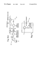
- the optical system 10 generally includes at least one optical transmitter 12 in optical communication with at least one optical receiver 14 via an optical transmission waveguide 15 , such as optical fiber, as shown in FIG. 1 .
- Each transmitter 12 is configured to transmit information via one or more information carrying optical signal wavelengths, or channels, ⁇ i , “signal wavelengths” that be combined into a wavelength division multiplexed (“WDM”) optical signal.
- WDM wavelength division multiplexed
- the term “information” should be broadly construed to include any type of audio or video signal, data, instructions, etc. that can be transmitted as optical signals.
- the transmitter 12 will generally include a laser as an optical source, but may include one or more other coherent or incoherent optical sources as is known in the art.
- the optical source in the transmitter can be tunable to provide flexible wavelength allocation in the system 10 .
- At least one of the optical receivers 14 is configured to receive the optical signal and a local oscillator wavelength ⁇ LO from a local optical source 16 .
- the optical receiver 14 down-converts two or more of the optical signal wavelengths ⁇ i to corresponding electrical signal frequencies ⁇ i , which can be further processed as may be appropriate in the system 10 .
- the local optical source 16 can also be tunable to provide further flexibility in wavelength allocation and detection.
- the tunable local optical source 16 and transmitter 12 can include temperature or external cavity tuned semiconductor or fiber lasers, as well as other tunable sources known in the art.
- the local oscillator wavelength ⁇ LO may be combined with the optical signal wavelengths ⁇ i proximate to the receiver 14 , at the transmitter 12 , or along the fiber 15 . It will be appreciated that introducing the local oscillator wavelength ⁇ LO proximate to the receiver 14 will maximize the local oscillator power available for coherent detection of the optical signal wavelengths ⁇ i .
- the system 10 may also include optical receivers 14 that include wavelength selective devices, i.e. Bragg gratings, etc., to provide for direct detection of the individual signal wavelengths ⁇ i .
- the transmitters 12 and receivers 14 can interface with other optical or electrical transmission systems as shown in FIG. 1 to reduce the number of transmitters and receivers used in the optical systems.
- the strategic use of direct and coherent detection receivers 14 in combination with modulating and upconverting transmitters 12 allows the transmission capacity to be cost-effectively deployed in a hybrid transmission system 10 .
- upconverting transmitters 12 and coherent detection receivers 14 can be used in the present invention to interconnect intensity modulated direct detection (IMDD) systems of the prior art.
- IMDD intensity modulated direct detection
- the receivers 20 can interface with transmitters in other systems directly, via electrical or optical cross-connects, ATM or IP routers, SONET/SDH add/drop multiplexers and short reach interfaces, or other protocols and interfaces. It will be further appreciated that systems 10 of the present invention can be interfaced with one or more other optical systems operating at the same or different wavelengths or wavelength ranges, i.e., 1300 and 1550 nm range.
- a plurality of transmitters 12 and receivers 14 can be employed in the system 10 by including one or more optical combiners 18 and optical distributors 20 .
- the combiners 18 and distributor 20 can be wavelength selective or non-selective, fiber or free space devices provided in one or more stages of varying bandwidths. For example, passive and WDM coupler and splitters, circulators and reflective element combinations, dichroic and other filters, as well as other multiplexers and demultiplexers can be deployed in various stages as may be necessary.
- Optical amplifiers 22 can also be provided to overcome losses associated with the combiners 18 and distributors 20 .
- one or more optical amplifiers 22 can be deployed along the span to optical regenerate the optical signal wavelengths ⁇ i to overcome signal attenuation.
- the optical amplifiers 22 can be remotely monitored and controlled using a supervisory channel by providing appropriate circuitry at the amplifier site as is known in the art. It will be appreciated that the present invention can be deployed in either unidirectional or bi-directional systems with appropriate modification to the combiners 18 , distributors 20 , amplifiers 22 , and other components within the system 10 .
- the optical amplifiers 22 used in the present invention can include doped fiber, such as erbium, and Raman fiber amplifiers, as well as other optical amplifiers known in the art. It is generally desirable to employ optical amplifiers 22 having substantially flat gain profiles over the range of information carrying signal wavelengths ⁇ i .
- the fiber amplifiers can be either locally or remotely pumped with optical energy depending on the system configuration.
- optical processing nodes 23 can also be disposed along the transmission fiber 15 and include optical add/drop devices 24 and transparent or opaque optical switches/routers 26 , in addition to transmitters 12 and receivers 14 .
- the add/drop devices 24 and switch/routers 26 can interconnect the nodes 23 using various techniques, such as those disclosed in commonly assigned U.S. patent application Ser. No. 09/119,562, which is incorporated herein by reference.
- the nodes 23 and amplifier 22 can be controlled either directly by a network manager 28 or remotely through other nodes 23 or amplifiers 22 via the supervisory channel.
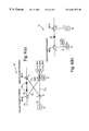
- information is transmitted on a plurality of signal wavelengths ⁇ i within a frequency bandwidth of electrical circuitry in the optical receiver 14 .
- the information can be transmitted on wavelengths ⁇ i provided by a single transmitter and/or a plurality of transmitters providing optical wavelengths within the frequency bandwidth of the receiver electronics.
- a photodiode 30 can be used in combination with the local oscillator wavelength ⁇ LO provided by the local optical source 16 to frequency downconvert the information carried by the optical signal wavelengths ⁇ i onto corresponding electrical signal frequencies ⁇ i within the frequency bandwidth of the receiver circuitry.
- Suitable receiver/local source combinations for coherent detection are known in the art; for example, see U.S. Pat. Nos. 4,989,200 and 5,432,632, which are incorporated herein by reference.
- the receivers 14 can include electrical filters and/or demultiplexers 32 to separate the multiple electrical signal frequencies, which can be passed through electrical signal processing circuits 34 to process, i.e., retime and reshape, the signals.
- the processed electrical signals ⁇ i will typically be further amplified using an electrical amplifier 36 before being provided to another optical or electrical system.
- the electrical output from the receiver 14 is provided as input to another optical system.
- information carried by the electrical signal frequencies can be used to directly modulate one or more optical sources 38 j,k,& m , such as lasers, to provide modulated optical signals at the optical source wavelengths ⁇ j,k,& m .
- the information carried by the electrical signal frequencies can be used to drive external modulators 40 , which modulate the information onto the optical wavelengths ⁇ j supplied by respective optical sources 38 j .
- one or more information carrying electrical signal frequencies ⁇ i can be multiplexed using an electrical multiplexer 41 and provided to an optical upconverter 42 .
- the upconverter 42 combines the electrical signal frequencies ⁇ i with the optical carrier ⁇ j to produce optical signals at different wavelengths ⁇ ji corresponding to the electrical signal frequencies ⁇ i .
- the transmitter 12 can transmit optical wavelengths ⁇ j that are the same as, or different than, the optical wavelengths ⁇ i received by the receiver 14 .
- the receiver/transmitter combination can be employed as an optical signal regenerator and/or a wavelength converter.
- the electrical processing circuit 34 can be further configured to compensate for optical signal distortion that occurs during optical transmission.
- the processing circuit 34 can include a group delay equalizer (FIG. 4) configured to compensate for chromatic dispersion or other optical distortion of the signal wavelength ⁇ i during transmission in the fiber 15 .
- FOG. 4 group delay equalizer
- one or more electrical circulators 44 are provided in combination with resonators 46 to compensate for distortion in a distorted electrical signal ⁇ ed and provide an undistorted electrical signal ⁇ e .
- the distortion compensation can be performed either on the electrical signal frequencies ⁇ i or following conversion to a baseband electrical signal carrying the information.
- optical add/drop devices 24 are provided along the length of the fiber 15 in a number of configurations shown in FIG. 5 .
- One or more receivers 14 and local optical sources 16 are provided in optical communication with the devices 24 to receive a plurality of drop signal wavelengths.
- Embodiments employing tunable local optical sources 16 provide for high capacity, flexible add/drop devices 24 for deployment in the system 10 .
- the add/drop devices 24 can also be used to provide full 2 ⁇ 2 switch or limited fixed wavelength add/drop functionality in the system 10 .
- the add/drop device 24 receives an input optical signal from the transmission fiber 15 1 at a first input port I.
- the input signal is distributed via a first continue path 15 c1 to a first output port O and/or a drop path 15 D to a second output, or drop, port D.
- optical signals from a second transmission fiber 15 2 are provided to the device 24 through a second input, or add, port A.
- the second input signal is provided via add path 15 A to the output port O and may also be distributed to the drop port D via second continue path 15 c2 .
- Wavelength selective or non-selective combiners and distributors can be used at the output ports and input ports depending upon the desired functionality of the add/drop device 24 , as previously described.
- the transmitters 12 and receivers 14 used in the add/drop devices 24 can be interconnected to form a non-terminal regenerator to overcome signal degradation or a wavelength converter in the system 10 (FIG. 5 ).
- the add/drop devices can also optically terminate the traffic or provide an interface with another optical system, such as a local ring, as further-shown in FIG. 5 .
- the add/drop device 24 can be configured as a 2 ⁇ 2 switch device employing couplers 48 and circulators 50 in combination with fiber Bragg gratings 52 , or other wavelength selective filters, to selectively pass wavelengths between the ports (FIG. 6 ( a )).
- fiber Bragg gratings 52 or other wavelength selective filters, to selectively pass wavelengths between the ports (FIG. 6 ( a )).
- Tunable or transient Bragg gratings 52 can be deployed in the continue paths 15 C1&2 in combination with the tunable receiver 14 to provide additional flexibility and wavelength reuse capability.
- the receiver 14 /local source 16 combinations can also be deployed with fixed wavelength add/drop devices 24 (FIG.
- the local optical source 16 can be tuned to or fixed at the wavelength of the reflective elements to provide for coherent detection of the selectively dropped signal wavelengths.
- the present invention provides for increased transmission capacity without the commensurate increase in equipment cost and complexity that is present in the prior art systems.
Abstract
Description
Claims (12)
Priority Applications (1)
| Application Number | Priority Date | Filing Date | Title |
|---|---|---|---|
| US09/326,748 US6661973B1 (en) | 1999-06-04 | 1999-06-04 | Optical transmission systems, apparatuses, and methods |
Applications Claiming Priority (1)
| Application Number | Priority Date | Filing Date | Title |
|---|---|---|---|
| US09/326,748 US6661973B1 (en) | 1999-06-04 | 1999-06-04 | Optical transmission systems, apparatuses, and methods |
Publications (1)
| Publication Number | Publication Date |
|---|---|
| US6661973B1 true US6661973B1 (en) | 2003-12-09 |
Family
ID=29711840
Family Applications (1)
| Application Number | Title | Priority Date | Filing Date |
|---|---|---|---|
| US09/326,748 Expired - Lifetime US6661973B1 (en) | 1999-06-04 | 1999-06-04 | Optical transmission systems, apparatuses, and methods |
Country Status (1)
| Country | Link |
|---|---|
| US (1) | US6661973B1 (en) |
Cited By (21)
| Publication number | Priority date | Publication date | Assignee | Title |
|---|---|---|---|---|
| US20020015207A1 (en) * | 2000-08-07 | 2002-02-07 | Hiroki Ooi | Method and system for compensating chromatic dispersion |
| US20020191251A1 (en) * | 2001-06-19 | 2002-12-19 | Ferguson Bruce A. | All optical switching routing system |
| US20030081281A1 (en) * | 2001-10-30 | 2003-05-01 | International Business Machines Corporation | WDMA free space broadcast technique for optical backplanes and interplanar communications |
| US20040208522A1 (en) * | 2001-11-08 | 2004-10-21 | Ian Dawes | Optical media management channel |
| EP1496636A1 (en) * | 2003-07-09 | 2005-01-12 | Lucent Technologies Inc. | Optical device with tunable coherent receiver |
| US20050069333A1 (en) * | 2003-09-25 | 2005-03-31 | Lucent Technologies Inc. | Multicasting optical switch fabric and method of detection based on novel heterodyne receiver |
| US20050169168A1 (en) * | 2002-06-25 | 2005-08-04 | Aronson Lewis B. | Integrated circuit with dual eye openers |
| US6985283B1 (en) * | 1998-06-16 | 2006-01-10 | Xtera Communications, Inc. | Fiber-optic compensation for dispersion, gain tilt, and band pump nonlinearity |
| US7095760B1 (en) * | 2000-03-20 | 2006-08-22 | Cortina Systems, Inc. | Routers for switching ATM cells in a packet-like manner using a packet switch |
| US7437079B1 (en) | 2002-06-25 | 2008-10-14 | Finisar Corporation | Automatic selection of data rate for optoelectronic devices |
| US7477847B2 (en) | 2002-09-13 | 2009-01-13 | Finisar Corporation | Optical and electrical channel feedback in optical transceiver module |
| US7561855B2 (en) | 2002-06-25 | 2009-07-14 | Finisar Corporation | Transceiver module and integrated circuit with clock and data recovery clock diplexing |
| US7664401B2 (en) | 2002-06-25 | 2010-02-16 | Finisar Corporation | Apparatus, system and methods for modifying operating characteristics of optoelectronic devices |
| US7809275B2 (en) | 2002-06-25 | 2010-10-05 | Finisar Corporation | XFP transceiver with 8.5G CDR bypass |
| US8965204B2 (en) | 2011-05-10 | 2015-02-24 | Invensys Systems, Inc. | Multi-drop optical communication |
| US9020350B2 (en) | 2011-06-24 | 2015-04-28 | Techsys Insights | Optical spectrum recovery |
| US20160057513A1 (en) * | 2013-04-03 | 2016-02-25 | British Telecommunications Public Limited Company | Optical switch |
| WO2017010605A1 (en) * | 2015-07-15 | 2017-01-19 | 한국과학기술원 | Device and method for free space coherent optical communication by means of automatic compensation for phase noise in atmosphere using optical comb of femtosecond laser |
| JP2017511036A (en) * | 2014-02-13 | 2017-04-13 | 華為技術有限公司Huawei Technologies Co.,Ltd. | Wavelength converter |
| KR101820652B1 (en) | 2017-07-19 | 2018-01-23 | 한국과학기술원 | apparatus and method for free space coherent optical communications with automatic compensation of phase noise in atmosphere using the optical comb of femtosecond lasers |
| US11316593B2 (en) | 2018-01-09 | 2022-04-26 | British Telecommunications Public Limited Company | Optical DWDM data and QKD transmission system |
Citations (17)
| Publication number | Priority date | Publication date | Assignee | Title |
|---|---|---|---|---|
| US4646361A (en) | 1983-03-10 | 1987-02-24 | Nec Corporation | Optical star repeater |
| US4736464A (en) | 1984-09-28 | 1988-04-05 | Bbc Brown, Boveri & Company Limited | Method for the additional transmission of information via a digital auxiliary channel, in an optical transmission system |
| US4807227A (en) | 1986-10-15 | 1989-02-21 | Nec Corporation | Optical wavelength-division switching system with coherent optical detection system |
| US5055795A (en) * | 1990-05-29 | 1991-10-08 | At&T Bell Laboratories | Traveling wave type transversal equalizer |
| US5134509A (en) | 1988-12-22 | 1992-07-28 | Gte Laboratories Incorporated | Coherent subcarrier multiplexed optical communication system |
| US5239401A (en) | 1990-12-31 | 1993-08-24 | Gte Laboratories Incorporated | Optical modulator for cancellation of second-order intermodulation products in lightwave systems |
| US5267073A (en) | 1989-10-30 | 1993-11-30 | Pirelli Cavi S.P.A. | Amplifier adapter for optical lines |
| US5349463A (en) * | 1990-08-17 | 1994-09-20 | Victor Company Of Japan | Optical radio repeater with signal quality detection |
| US5452115A (en) | 1993-04-22 | 1995-09-19 | Kabushiki Kaisha Toshiba | Communications system |
| US5467212A (en) | 1993-06-04 | 1995-11-14 | Huber; David R. | Addressable grating modulation system for optical cable TV system |
| US5504609A (en) | 1995-05-11 | 1996-04-02 | Ciena Corporation | WDM optical communication system with remodulators |
| US5596436A (en) | 1995-07-14 | 1997-01-21 | The Regents Of The University Of California | Subcarrier multiplexing with dispersion reduction and direct detection |
| US5784184A (en) | 1995-05-11 | 1998-07-21 | Ciena Corporation | WDM Optical communication systems with remodulators and remodulating channel selectors |
| US5801858A (en) * | 1996-06-25 | 1998-09-01 | Northern Telecom Limited | Optical transmission systems using optical amplifiers and wavelength division multiplexing |
| US5896211A (en) * | 1990-09-14 | 1999-04-20 | Fujitsu Limited | Optical communication system |
| US6118566A (en) | 1998-11-04 | 2000-09-12 | Corvis Corporation | Optical upconverter apparatuses, methods, and systems |
| US6222658B1 (en) * | 1998-08-06 | 2001-04-24 | Harris Corporation | Method and apparatus for a free space optical non-processing satellite transponder |
-
1999
- 1999-06-04 US US09/326,748 patent/US6661973B1/en not_active Expired - Lifetime
Patent Citations (17)
| Publication number | Priority date | Publication date | Assignee | Title |
|---|---|---|---|---|
| US4646361A (en) | 1983-03-10 | 1987-02-24 | Nec Corporation | Optical star repeater |
| US4736464A (en) | 1984-09-28 | 1988-04-05 | Bbc Brown, Boveri & Company Limited | Method for the additional transmission of information via a digital auxiliary channel, in an optical transmission system |
| US4807227A (en) | 1986-10-15 | 1989-02-21 | Nec Corporation | Optical wavelength-division switching system with coherent optical detection system |
| US5134509A (en) | 1988-12-22 | 1992-07-28 | Gte Laboratories Incorporated | Coherent subcarrier multiplexed optical communication system |
| US5267073A (en) | 1989-10-30 | 1993-11-30 | Pirelli Cavi S.P.A. | Amplifier adapter for optical lines |
| US5055795A (en) * | 1990-05-29 | 1991-10-08 | At&T Bell Laboratories | Traveling wave type transversal equalizer |
| US5349463A (en) * | 1990-08-17 | 1994-09-20 | Victor Company Of Japan | Optical radio repeater with signal quality detection |
| US5896211A (en) * | 1990-09-14 | 1999-04-20 | Fujitsu Limited | Optical communication system |
| US5239401A (en) | 1990-12-31 | 1993-08-24 | Gte Laboratories Incorporated | Optical modulator for cancellation of second-order intermodulation products in lightwave systems |
| US5452115A (en) | 1993-04-22 | 1995-09-19 | Kabushiki Kaisha Toshiba | Communications system |
| US5467212A (en) | 1993-06-04 | 1995-11-14 | Huber; David R. | Addressable grating modulation system for optical cable TV system |
| US5504609A (en) | 1995-05-11 | 1996-04-02 | Ciena Corporation | WDM optical communication system with remodulators |
| US5784184A (en) | 1995-05-11 | 1998-07-21 | Ciena Corporation | WDM Optical communication systems with remodulators and remodulating channel selectors |
| US5596436A (en) | 1995-07-14 | 1997-01-21 | The Regents Of The University Of California | Subcarrier multiplexing with dispersion reduction and direct detection |
| US5801858A (en) * | 1996-06-25 | 1998-09-01 | Northern Telecom Limited | Optical transmission systems using optical amplifiers and wavelength division multiplexing |
| US6222658B1 (en) * | 1998-08-06 | 2001-04-24 | Harris Corporation | Method and apparatus for a free space optical non-processing satellite transponder |
| US6118566A (en) | 1998-11-04 | 2000-09-12 | Corvis Corporation | Optical upconverter apparatuses, methods, and systems |
Non-Patent Citations (6)
| Title |
|---|
| "SONET Regenerator (SONET RGTR) Equipment Generic Criteria", Dec. 1990, Bellcore Technical Reference, TR-NWT-000917, Issue 1. |
| Aoki, Y., et al., "Unrepeatered Transmission of Four-Channel 2.5 Gb/s WDM Signal over 360km of Conventional Fiber with Fully-Engineered Equipments", Dec. 3-6, 1995, 20<th >Australian Conference on Optical Fibre Technology (ACOFT '95), Coolum Beach, Queensland, Australia. |
| Aoki, Y., et al., "Unrepeatered Transmission of Four-Channel 2.5 Gb/s WDM Signal over 360km of Conventional Fiber with Fully-Engineered Equipments", Dec. 3-6, 1995, 20th Australian Conference on Optical Fibre Technology (ACOFT '95), Coolum Beach, Queensland, Australia. |
| Diner, F., et al., "Network Design Considerations of n-Channel WDM Architectures with EDFAs For Central Office Applications", Jun. 18-22, 1995, National Fiber Optic Engineers Conference, pp. 1207-1214, Boston, MA USA. |
| Thombley, L., et al., "Project OART-WDM, EDFA's and Mixed Data Rates in a Real-World Testbed", NFOEC '94 , pp. 283-294. |
| Thombley, L., et al., "Project OART—WDM, EDFA's and Mixed Data Rates in a Real-World Testbed", NFOEC '94 , pp. 283-294. |
Cited By (35)
| Publication number | Priority date | Publication date | Assignee | Title |
|---|---|---|---|---|
| US6985283B1 (en) * | 1998-06-16 | 2006-01-10 | Xtera Communications, Inc. | Fiber-optic compensation for dispersion, gain tilt, and band pump nonlinearity |
| US7095760B1 (en) * | 2000-03-20 | 2006-08-22 | Cortina Systems, Inc. | Routers for switching ATM cells in a packet-like manner using a packet switch |
| US20020015207A1 (en) * | 2000-08-07 | 2002-02-07 | Hiroki Ooi | Method and system for compensating chromatic dispersion |
| US6925262B2 (en) * | 2000-08-07 | 2005-08-02 | Fujitsu Limited | Method and system for compensating chromatic dispersion |
| US20020191251A1 (en) * | 2001-06-19 | 2002-12-19 | Ferguson Bruce A. | All optical switching routing system |
| US6970649B2 (en) * | 2001-10-30 | 2005-11-29 | International Business Machines Corporation | WDMA free space broadcast technique for optical backplanes and interplanar communications |
| US20030081281A1 (en) * | 2001-10-30 | 2003-05-01 | International Business Machines Corporation | WDMA free space broadcast technique for optical backplanes and interplanar communications |
| US20040208522A1 (en) * | 2001-11-08 | 2004-10-21 | Ian Dawes | Optical media management channel |
| US7146101B2 (en) * | 2001-11-08 | 2006-12-05 | Altera Corporation | Optical media management channel |
| US7437079B1 (en) | 2002-06-25 | 2008-10-14 | Finisar Corporation | Automatic selection of data rate for optoelectronic devices |
| US7613393B2 (en) | 2002-06-25 | 2009-11-03 | Finisar Corporation | Transceiver module and integrated circuit with dual eye openers and integrated loopback and bit error rate testing |
| US7995927B2 (en) | 2002-06-25 | 2011-08-09 | Finisar Corporation | Transceiver module and integrated circuit with dual eye openers |
| US7099382B2 (en) * | 2002-06-25 | 2006-08-29 | Finisar Corporation | Integrated circuit with dual eye openers |
| US7835648B2 (en) | 2002-06-25 | 2010-11-16 | Finisar Corporation | Automatic selection of data rate for optoelectronic devices |
| US7809275B2 (en) | 2002-06-25 | 2010-10-05 | Finisar Corporation | XFP transceiver with 8.5G CDR bypass |
| US7664401B2 (en) | 2002-06-25 | 2010-02-16 | Finisar Corporation | Apparatus, system and methods for modifying operating characteristics of optoelectronic devices |
| US20050169168A1 (en) * | 2002-06-25 | 2005-08-04 | Aronson Lewis B. | Integrated circuit with dual eye openers |
| US7486894B2 (en) | 2002-06-25 | 2009-02-03 | Finisar Corporation | Transceiver module and integrated circuit with dual eye openers |
| US7561855B2 (en) | 2002-06-25 | 2009-07-14 | Finisar Corporation | Transceiver module and integrated circuit with clock and data recovery clock diplexing |
| US7567758B2 (en) | 2002-06-25 | 2009-07-28 | Finisar Corporation | Transceiver module and integrated circuit with multi-rate eye openers and bypass |
| US7477847B2 (en) | 2002-09-13 | 2009-01-13 | Finisar Corporation | Optical and electrical channel feedback in optical transceiver module |
| EP1496636A1 (en) * | 2003-07-09 | 2005-01-12 | Lucent Technologies Inc. | Optical device with tunable coherent receiver |
| US7269356B2 (en) | 2003-07-09 | 2007-09-11 | Lucent Technologies Inc. | Optical device with tunable coherent receiver |
| US20050008369A1 (en) * | 2003-07-09 | 2005-01-13 | Winzer Peter J. | Optical device with tunable coherent receiver |
| US7373091B2 (en) * | 2003-09-25 | 2008-05-13 | Lucent Technologies Inc. | Multicasting optical switch fabric and method of detection based on novel heterodyne receiver |
| US20050069333A1 (en) * | 2003-09-25 | 2005-03-31 | Lucent Technologies Inc. | Multicasting optical switch fabric and method of detection based on novel heterodyne receiver |
| US8965204B2 (en) | 2011-05-10 | 2015-02-24 | Invensys Systems, Inc. | Multi-drop optical communication |
| US9020350B2 (en) | 2011-06-24 | 2015-04-28 | Techsys Insights | Optical spectrum recovery |
| US20160057513A1 (en) * | 2013-04-03 | 2016-02-25 | British Telecommunications Public Limited Company | Optical switch |
| US9693123B2 (en) * | 2013-04-03 | 2017-06-27 | British Telecommunications Public Limited Company | Optical switch |
| JP2017511036A (en) * | 2014-02-13 | 2017-04-13 | 華為技術有限公司Huawei Technologies Co.,Ltd. | Wavelength converter |
| WO2017010605A1 (en) * | 2015-07-15 | 2017-01-19 | 한국과학기술원 | Device and method for free space coherent optical communication by means of automatic compensation for phase noise in atmosphere using optical comb of femtosecond laser |
| US10425155B2 (en) | 2015-07-15 | 2019-09-24 | Korea Advanced Institute Of Science And Technology | Device and method for free space coherent optical communication by means of automatic compensation for phase noise in atmosphere using femtosecond laser optical comb |
| KR101820652B1 (en) | 2017-07-19 | 2018-01-23 | 한국과학기술원 | apparatus and method for free space coherent optical communications with automatic compensation of phase noise in atmosphere using the optical comb of femtosecond lasers |
| US11316593B2 (en) | 2018-01-09 | 2022-04-26 | British Telecommunications Public Limited Company | Optical DWDM data and QKD transmission system |
Similar Documents
| Publication | Publication Date | Title |
|---|---|---|
| US6661973B1 (en) | Optical transmission systems, apparatuses, and methods | |
| US7317877B2 (en) | Optical communications systems, devices, and methods | |
| US5995256A (en) | Method and system for managing optical subcarrier reception | |
| US7088500B2 (en) | Optical communication systems including optical amplifiers and amplification methods | |
| US6922529B2 (en) | Optical communications systems, devices, and methods | |
| US7343097B2 (en) | Optical transmission systems including optical amplifiers and methods of use therein | |
| US20030170028A1 (en) | Optical transmitter, optical repeater, optical receiver and optical transmission method | |
| US6005997A (en) | Long-haul terrestrial optical fiber link having low-power optical line amplifiers with integrated dispersion compensation modules | |
| US6954590B2 (en) | Optical transmission systems and optical receivers and receiving methods for use therein | |
| US8195048B2 (en) | Optical transport system architecture for remote terminal connectivity | |
| US7697802B2 (en) | Optical bypass method and architecture | |
| US20190103917A1 (en) | Optical Pumping Technique | |
| JP7159561B2 (en) | Low-Noise Achromatic, Directionless, Contention-Free Reconfigurable Optical Add/Drop Multiplexer | |
| US6920277B2 (en) | Optical bypass method and architecture | |
| CA2414458C (en) | Optical transmission systems including optical amplifiers and methods of use therein | |
| AU2001276858A1 (en) | Optical transmission systems including optical amplifiers and methods of use therein |
Legal Events
| Date | Code | Title | Description |
|---|---|---|---|
| AS | Assignment |
Owner name: CORVIS CORPORATION, MARYLAND Free format text: ASSIGNMENT OF ASSIGNORS INTEREST;ASSIGNORS:HUBER, DAVID R.;PRICE, ALISTAIR J.;REEL/FRAME:010017/0739 Effective date: 19990604 |
|
| STCF | Information on status: patent grant |
Free format text: PATENTED CASE |
|
| FEPP | Fee payment procedure |
Free format text: PAT HOLDER NO LONGER CLAIMS SMALL ENTITY STATUS, ENTITY STATUS SET TO UNDISCOUNTED (ORIGINAL EVENT CODE: STOL); ENTITY STATUS OF PATENT OWNER: LARGE ENTITY |
|
| AS | Assignment |
Owner name: BROADWING CORPORATION, TEXAS Free format text: CHANGE OF NAME;ASSIGNOR:CORVIS CORPORATION;REEL/FRAME:019323/0858 Effective date: 20041007 |
|
| FPAY | Fee payment |
Year of fee payment: 4 |
|
| FPAY | Fee payment |
Year of fee payment: 8 |
|
| AS | Assignment |
Owner name: BROADWING, LLC, COLORADO Free format text: CHANGE OF NAME;ASSIGNOR:BROADWING CORPORATION;REEL/FRAME:026299/0605 Effective date: 20081230 |
|
| AS | Assignment |
Owner name: LEVEL 3 COMMUNICATIONS, LLC, COLORADO Free format text: ASSIGNMENT OF ASSIGNORS INTEREST;ASSIGNOR:BROADWING, LLC;REEL/FRAME:026533/0440 Effective date: 20110630 |
|
| FPAY | Fee payment |
Year of fee payment: 12 |
|
| AS | Assignment |
Owner name: OPTIC153 LLC, DELAWARE Free format text: ASSIGNMENT OF ASSIGNORS INTEREST;ASSIGNOR:LEVEL 3 COMMUNICATIONS, LLC;REEL/FRAME:056469/0773 Effective date: 20170411 |