US6659533B1 - Vehicle convertible roof - Google Patents
Vehicle convertible roof Download PDFInfo
- Publication number
- US6659533B1 US6659533B1 US10/237,919 US23791902A US6659533B1 US 6659533 B1 US6659533 B1 US 6659533B1 US 23791902 A US23791902 A US 23791902A US 6659533 B1 US6659533 B1 US 6659533B1
- Authority
- US
- United States
- Prior art keywords
- roof
- frame
- backwindow
- stowed
- raised
- Prior art date
- Legal status (The legal status is an assumption and is not a legal conclusion. Google has not performed a legal analysis and makes no representation as to the accuracy of the status listed.)
- Expired - Fee Related
Links
Images


Classifications
-
- B—PERFORMING OPERATIONS; TRANSPORTING
- B60—VEHICLES IN GENERAL
- B60J—WINDOWS, WINDSCREENS, NON-FIXED ROOFS, DOORS, OR SIMILAR DEVICES FOR VEHICLES; REMOVABLE EXTERNAL PROTECTIVE COVERINGS SPECIALLY ADAPTED FOR VEHICLES
- B60J7/00—Non-fixed roofs; Roofs with movable panels, e.g. rotary sunroofs
- B60J7/08—Non-fixed roofs; Roofs with movable panels, e.g. rotary sunroofs of non-sliding type, i.e. movable or removable roofs or panels, e.g. let-down tops or roofs capable of being easily detached or of assuming a collapsed or inoperative position
- B60J7/12—Non-fixed roofs; Roofs with movable panels, e.g. rotary sunroofs of non-sliding type, i.e. movable or removable roofs or panels, e.g. let-down tops or roofs capable of being easily detached or of assuming a collapsed or inoperative position foldable; Tensioning mechanisms therefor, e.g. struts
- B60J7/1226—Soft tops for convertible vehicles
- B60J7/1265—Soft tops for convertible vehicles characterised by kinematic movements, e.g. using parallelogram linkages
Definitions
- This invention relates generally to roofs for automotive vehicles and, more particularly, to a convertible roof and backlite.
- Traditional soft-top convertible roofs for automotive vehicles typically employ four or five roof bows, most of which have an inverted U-shape spanning transversely across the vehicle for supporting a vinyl, canvas or polyester fabric, pliable roof cover.
- a number one roof bow is mounted to a pair of front roof rails and is typically latched to a stationary front header panel of the automotive vehicle body disposed above the front windshield.
- a number two bow is typically mounted to a pair of center roof rails which are pivotally connected to the front roof rails.
- the number three, four and any additional optional roof bows are commonly mounted to a pair of rear roof rails which are pivotally coupled to the center roof rails.
- the roof cover can also have a hard or rigid portion along with the pliable portion.
- Traditional soft-top convertible roofs have a backwindow, known as a backlite, that retracts with the convertible roof into the stowage compartment.
- a backlite that retracts with the convertible roof into the stowage compartment.
- these backlites are angled, when raised, to provide a desired appearance to the vehicle and to facilitate folding of the convertible roof.
- traditional soft-top convertible roofs can employ a powered actuator for controlling the folding mechanism that retracts the convertible roof.
- the rear portion of the convertible roof which includes the backlite and/or frame surrounding the backlite is passively controlled and rely upon the movement of the flexible cover to position the backlite and/or frame when the convertible roof is transitioned from raised and stowed positions.
- second and subsequent roof bows of traditional soft-top convertible roofs are also typically passively controlled and rely upon the movement of the flexible cover to position the roof bows when the convertible roof is transitioned from raised and stowed positions.
- the passively controlled roof bows may interfere with the rigid frame and/or backlite when the convertible roof is retracted to its stowed position. This potential is most pronounced in a roof bow immediately forward of the frame.
- a convertible roof which includes a backlite that is substantially vertical when the convertible roof is in a raised position. Another aspect of the present invention retains a portion of a backlite within a frame that retracts with the folding of a convertible roof. A further and optional aspect of the present invention employs a backlite which can be independently retracted such that a backlite frame does not retain the backlite when the backlite is retracted.
- an automatically powered actuator is used to actively control the retraction of a convertible roof and a backlite frame.
- a roof bow immediately forward of a backlite frame and/or backlite is actively controlled.
- Still another aspect of the present invention discloses a unique and novel way to control the folding of a convertible roof mechanism such that a backlite frame (and backlite when not independently retractable) retracts first, is stowed below a folding mechanism, and has a linkage mechanism that is driven by an automatically powered actuator with the rest of the folding mechanism.
- a vehicle having fore and aft seating areas, a storage area, and a convertible roof which has substantially nothing above a fore-aft belt line of the vehicle, rearward of the A-pillar when the convertible roof is in the stowed position, is also disclosed in yet a further aspect of the present invention.
- a substantially vertical backlite is provided in conjunction with a convertible roof to provide a vehicle with a “station wagon” or “sport utility vehicle” look.
- a convertible roof extends substantially to the rear of a vehicle with a backlite and rear of the convertible roof being substantially vertical.
- a backlite can be retracted independently of a convertible roof to allow access to a rear of a vehicle without retracting the convertible roof.
- a controlled retraction of the backlite and/or backlite frame into a stowage compartment is provided to minimize a required stowage area and provide a more compact folded convertible roof.
- an automatically powered actuator is used to retract the backlite and/or backlite frame along with a convertible roof in order to simplify the convertible roof and minimize cost.
- Accurately controlling a roof bow immediately forward of a backlite frame to prevent this roof bow from interfering with the backlite frame and/or backlite when the convertible roof is retracted to a stowed position is also provided.
- FIG. 1A is a side elevation view showing the preferred embodiment of a vehicle with a convertible roof in a raised operative position in accordance with the principles of the present invention
- FIG. 1B is a perspective view of the rear of the vehicle of FIG. 1A;
- FIGS. 2A and 2B are side elevation views of the vehicle of FIG. 1A showing the convertible roof folding mechanism in accordance with the principles of the present invention in different midpoint positions between the raised and stowed positions;
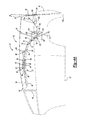
- FIG. 3A is a side elevation view of the vehicle of FIG. 1A showing the convertible roof folding mechanism in accordance with the principle of the present invention in a stowed position;
- FIG. 3B is a top elevation view of the vehicle of FIG. 3A;
- FIGS. 4A and 4B are side elevation views showing an alternate embodiment of a vehicle having a convertible roof in accordance with the principles of the present invention with an independently retractable backlite in an extended position and retracted position respectively;
- FIG. 4C is a side elevation view of the vehicle of FIG. 4A showing the convertible roof folding mechanism in accordance with the principles of the present invention in a midpoint position between the raised and stowed positions and the backlite in a retracted position;
- FIG. 4D is a side elevation view of the vehicle of FIG. 4A showing the convertible roof folding mechanism in accordance with the principles of the present invention in a stowed position and the backlite in a retracted position.
- FIGS. 1-3 show a first preferred embodiment of a convertible roof 20 of the present invention while FIGS. 4 A—D show an alternate embodiment of a convertible roof 20 of the present invention.
- Convertible roof 20 is employed on an automotive vehicle 22 having a passenger compartment 24 and a storage compartment 26 located aft of passenger compartment 24 .
- Passenger compartment 24 has first and second seating areas 28 and 30 .
- Second seating area 30 is positioned rearward or aft of first seating area 28 and forward or fore of storage compartment 26 .
- Each of the seating areas 28 and 30 contain a soft seating surface on which an occupant of vehicle 22 can sit.
- Seating areas 28 and 30 and storage compartment 26 are arranged such that in the interior of vehicle 22 , storage compartment 26 is accessible from seating areas 28 and 30 .
- Convertible roof 20 is of the type utilizing a folding or top stack mechanism 32 that partially supports a roof cover 34 and is operable between a fully raised position, as shown in FIGS. 1A and 4A, and a fully stowed position, as shown in FIG. 3A and 4C.
- Roof cover 34 is made from a pliable material, such as vinyl, canvas or a polyester fabric. If desired, roof cover 34 can also include a hard portion (not shown) depending upon the desired look and appearance of the convertible roof 20 .
- Convertible roof 20 also includes a backlite 36 that is retained within a frame 38 of folding mechanism 32 .
- Backlite 36 as shown in FIGS. 1-3, can be integral to frame 38 and move as a unitary piece with frame 38 when folding mechanism 32 is moved between the raised and stowed positions.
- backlite 36 ′ is retractable independently of folding mechanism 32 . That is, backlite 36 ′ can retract into a tailgate or rear stowage compartment 40 independently and separately from folding mechanism 32 and frame 38 , as described in more detail below.
- convertible roof 20 and folding mechanism 32 are shown symmetrical about a longitudinal, fore-and-aft centerline (not shown) of vehicle 22 .
- Folding mechanism 32 includes right and left roof linkages on the respective right and left sides of vehicle 22 .
- right side linkages are also provided as part of folding mechanism 32 and are mirrored images of the left side.
- forward and reverse refers to the orientation of the components when folding mechanism 32 is in the fully raised position.
- Folding mechanism 32 includes a first roof bow 42 that extends transversely across vehicle 22 and has a front edge 44 that is latched to a stationary front header panel of vehicle 22 disposed above the front windshield when in the fully raised position, as shown in FIG. 1 A.
- Vehicle 22 has an A-pillar 46 that extends along the front windshield and across which the stationary front header panel of vehicle 22 extends.
- Cover 34 is attached to first roof bow 42 .
- First roof bow 42 is fixedly connected to a front roof rail 48 .
- first roof bow 42 can be formed integrally with front roof rail 48 .
- first roof bow 42 and front roof rail 48 can be integrally cast from aluminum or a magnesium alloy.
- Front roof rail 48 is pivotally coupled to a center roof rail 50 by a multi-link hinge assembly (MHA) 52 .
- MHA 52 controls rotation of front roof rail 48 relative to center roof rail 50 .
- MHA multi-link hinge assembly
- MHA 52 includes a pivot connection 54 between a back end portion of front roof rail 48 and a front end portion of center roof rail 50 .
- One end of a first link 56 is pivotally connected to an intermediate back end portion of front roof rail 48 at pivot 58 while an opposite end is pivotally connected to an end of a second link 60 at pivot 62 .
- An opposite end of second link 62 is pivotally connected to the front end portion of center roof rail 50 at pivot 64 .
- MHA 52 is a 4-bar linkage that includes front roof rail 48 , first link 56 , second link 60 , and center roof rail 50 .
- a second roof bow 66 is fixedly attached to second link 60 adjacent pivot 62 .
- second roof bow 66 can be formed integrally with second link 60 in a similar manner as described above with forming first roof bow 42 integrally with front roof rail 48 .
- the fixed connection between second roof bow 66 and second link 60 causes second roof bow 66 to be actively controlled by second link 60 .
- Movement of MHA 52 is controlled by a first control link 68 which is pivotally coupled to MHA 52 .
- a front end portion of first control link 68 is pivotally connected to second link 60 at pivot 70 .
- center roof rail 50 is pivotally connected to an intermediate front end portion of a rear roof rail 72 at pivot 74 , while a back end portion of center roof rail 50 is pivotally connected to an end of a balance link 76 at pivot 78 .
- An opposite end of balance link 76 is pivotally connected to a fixed plate 79 at pivot 80 .
- Fixed plate 79 is rigidly attached to vehicle 22 so that fixed plate 79 acts as a stationary extension of vehicle 22 .
- a back end portion of rear roof rail 72 is pivotally connected to fixed plate 79 at pivot 82 .
- center roof rail 50 The pivotable connections between center roof rail 50 , rear roof rail 72 , balance link 76 , and fixed plate 79 form a 4-bar linkage assembly defined by pivots 74 , 78 , 80 and 82 that controls the rotation of center roof rail 50 relative to rear roof rail 72 along with controlling the movement of folding mechanism 32 , as described in more detail below.
- a third roof bow 84 is fixedly connected to a front end portion of rear roof rail 72 .
- third roof bow 84 can be formed integrally with rear roof rail 72 in a similar manner as described above with forming first roof bow 42 integrally with front roof rail 48 .
- third roof bow 84 is fixedly connected to rear roof rail 72
- movement of third roof bow 84 is actively controlled by movement of rear roof rail 72 .
- Rear roof rail 72 also controls movement of MHA 52 via first control link 68 .
- an integral extension of a front end portion of rear roof rail 72 is pivotally connected to an end of first control link 68 at pivot 86 .
- the pivotable connection between first control link 68 and rear roof rail 72 allows rear roof rail 72 to control the movement of front roof rail 48 and second bow 66 via MHA 52 .
- One end of a fourth roof bow 88 is pivotally connected to fixed plate 79 at pivot 82 along with the back end portion of rear roof rail 72 .
- An intermediate portion of fourth roof bow 88 is pivotally connected to an intermediate portion of balance link 76 at pivot 92 .
- the pivotable connection between fourth roof bow 88 and balance link 76 allows movement of fourth roof bow 88 to be actively controlled by movement of balance link 76 .
- fourth roof bow 88 is actively controlled when folding mechanism 32 moves between the raised and stowed positions.
- a rear lower portion of frame 38 is pivotally connected to vehicle 22 at pivot 94 .
- Pivot 94 allows frame 38 to pivot forwardly when folding mechanism 32 is being moved from the raised to the stowed position.
- the pivotal movement of frame 38 about pivot 94 is controlled by rear roof rail 72 via a second control link 96 .
- a first end of second control link 96 is pivotally connected to a back end portion of rear roof rail 72 at pivot 98 while a second end of second control link 96 is pivotally coupled to frame 38 via a third link 100 .
- second end of second control link 96 is pivotally connected to a first end of third link 100 at pivot 102 while a second end of third link 100 is pivotally connected to frame 38 at pivot 104 .
- one end of a fourth link 106 is pivotally connected to fixed plate 79 at pivot 108 while an opposite end of fourth link 106 is pivotally connected to an intermediate portion of second control link 96 at pivot 110 .
- the pivotable connections between rear roof rail 72 , second control link 96 , fourth link 106 and fixed plate 79 form a 4-bar linkage defined by pivots 98 , 110 , 108 , and 82 .
- This 4-bar linkage controls the movement of second control link 96 and, thus, rotation of frame 38 about pivot 94 via third link 100 . Therefore, movement of rear roof rail 72 controls the movement of frame 38 via second control link 96 .
- Rear roof rail 72 controls movement of folding mechanism 32 and, thus, serves as a driving link for folding mechanism 32 .
- Movement of rear roof rail 72 relative to vehicle 22 is controlled by a powered driving element or actuator 112 .
- Powered actuator 112 can take a variety of forms, as known in the art.
- powered actuator 112 can be an electric motor, a fluid actuated piston, a geared driving element, or a cable, among others.
- folding mechanism 32 can be manually driven.
- folding mechanism 32 is shown in its fully raised position corresponding to roof cover 34 covering the passenger compartment 24 and storage compartment 26 of vehicle 22 .
- front roof rail 48 , center roof rail 50 and rear roof rail 72 are all generally aligned and first roof bow 42 , second roof bow 66 , third roof bow 84 , fourth roof bow 88 , and frame 38 are fully extended so that roof cover 34 is taut and backlite 36 is substantially vertical.
- a backlite is considered to be substantially vertical when the angle a between the backlite and a vertical axis 114 is less than about 35 degrees. That is, a substantially vertical backlite is angled relative to a vertical axis 114 in the range of about 0 to 35 degrees in either direction toward horizontal.
- first roof bow 42 is unlatched from the front header and A-pillar 56 of vehicle 22 , as is known in the art, and powered actuator 112 begins to cause rear roof rail 72 to rotate about pivot 82 in a clockwise direction when folding mechanism 32 is viewed from the perspective shown in the figures.
- actuator 112 continues to rotate rear roof rail 72 clockwise about pivot 82 , frame 38 and backlite 36 continue to rotate forwardly and enter storage compartment 26 first.
- Actuator 112 continues to drive rear roof rail 72 clockwise about pivot 82 until frame 38 is completely within storage compartment 26 and the remainder of folding mechanism 22 is positioned above frame 38 , as shown in FIG. 3 A.
- each of the roof bows 42 , 66 , 84 , and 88 are actively controlled. Actively controlling the roof bows 42 , 66 , 84 , and 88 prevents the roof bows 42 , 66 , 84 and 88 from interfering with frame 38 and backlite 36 when folding mechanism 22 is moved from the raised position to the stowed position. Additionally, actively controlling the roof bows 42 , 66 , 84 , and 88 allows folding mechanism 22 to be packaged within close tolerances and, thus, folding mechanism 22 can occupy a smaller space in storage compartment 26 .
- convertible roof 20 When convertible roof 20 is in the fully stowed position, vehicle 22 has substantially nothing above a fore-aft beltline 114 from A-pillar 46 rearward to the back of vehicle 22 .
- This configuration of convertible roof 20 provides a novel and unique appearance for vehicle 22 , in that it can give the appearance of a station wagon or SUV with the convertible roof 20 in the fully raised position while providing a top down motoring experience of a convertible vehicle with convertible roof 20 in the stowed position.
- the station wagon or SUV appearance is characterized as having an interior with passenger compartment 24 having first seating area 28 positioned in front of second seating area 30 and storage compartment 26 positioned behind passenger compartment 24 with storage compartment 26 being accessible from the interior of vehicle 22 and, more specifically, from passenger compartment 24 along with having backlite 36 substantially vertical.
- folding mechanism 32 is shown in its fully stowed position which corresponds to being located within storage compartment 26 . As can be seen, folding mechanism 32 folds in an accordion-type fashion so that folding mechanism 32 folds and stacks upon itself with frame 38 located in a bottommost position of storage compartment 26 .
- folding mechanism 32 When convertible roof 20 is moved from its stowed position to its raised position, folding mechanism 32 operates in a reverse fashion.
- Actuator 112 is operated to cause rear roof rail 72 to rotate about pivot 82 in a counterclockwise direction.
- the counterclockwise rotation of rear roof rail 72 causes first control link 68 and center roof rail 50 to move forwardly and center roof rail 50 to rotate clockwise relative to rear roof rail 72 and balance link 76 .
- the forwardly movement of first control link 68 causes MHA 52 to rotate front roof rail 48 counterclockwise relative to center roof rail 50 .
- Rotation of rear roof rail 72 counterclockwise also causes second control link 96 to move upwardly and forwardly which causes frame 38 to move upwardly and rotate clockwise about pivot 94 .
- folding mechanism 32 causes roof cover 34 to expand and begin to unfold along with folding mechanism 32 .
- roof cover 34 is taut and front edge 44 of first roof bow 42 can be latched to the front header of vehicle 22 above the front windshield.
- the active controlling of the roof bows 42 , 66 , 84 and 88 position the bows in a desired orientation so that roof cover 34 is taut and provides a desired appearance.
- convertible roof 20 employs a backlite 36 ′ that is independently retractable from folding mechanism 32 .
- backlite 36 ′ moves between an extended position, wherein backlite 36 ′ is retained in frame 38 , as shown in FIG. 4A, and a retracted position wherein backlite 36 ′ is retained in tailgate 40 , as shown in FIGS. 4B-D.
- frame 38 engages with and retains three sides of backlite 36 ′.
- backlite 36 ′ When backlite 36 ′ is in its retracted position, frame 38 is not engaged with backlite 36 ′ and is free to move with folding mechanism 32 without moving backlite 36 ′.
- Retraction of backlite 36 ′ can be accomplished in a variety of ways, as is known in the art.
- backlite 36 ′ can be connected to a track roller system with nylon rollers, similar to a glass guide on a door glass mechanism, that moves backlite 36 ′ between the extended and retracted positions.
- backlite 36 ′ By allowing backlite 36 ′ to be retracted when convertible roof 20 is in its fully raised position, access to storage compartment 26 can be achieved from outside vehicle 22 through the opening in frame 38 when backlite 36 ′ is in its retracted position in tailgate 40 .
- actuator 112 When it is desired to return convertible roof 20 to its fully raised position, actuator 112 causes rear roof rail 72 to rotate clockwise about pivot 82 to unfold and extend folding mechanism 32 across passenger compartment 24 and storage compartment 26 . Once folding mechanism 32 has been completely unfolded, backlite 36 ′ can then be extended into frame 38 to complete the enclosure of passenger compartment 24 and storage compartment 26 with convertible roof 20 .
- the present invention provides a unique and novel convertible roof 20 for use with a vehicle 22 .
- the present invention provides for a convertible roof 20 having roof bows that are all actively controlled, a frame 38 for retaining a backlite 36 , 36 ′ that is actively controlled and falls first into storage compartment 26 and resides below the roof rails and roof bows of folding mechanism 32 when in the stowed position.
- the present invention also provides a clean look for a vehicle 22 by having substantially nothing above beltline 116 from A-pillar 46 back when convertible roof 20 is in its stowed position.
- folding mechanism 32 including frame 36 can be powered by the same actuator 112 .
- MHA 52 may have more links than a 4-bar linkage.
- the specific connections of the various pivots can be altered to provide desired kinematics of convertible roof 20 .
- the specific configurations and orientations of the various linkages, bows and rails can have shapes that differ from those shown and still be within the scope of the present invention.
Abstract
Description
Claims (61)
Priority Applications (1)
| Application Number | Priority Date | Filing Date | Title |
|---|---|---|---|
| US10/237,919 US6659533B1 (en) | 2002-09-09 | 2002-09-09 | Vehicle convertible roof |
Applications Claiming Priority (1)
| Application Number | Priority Date | Filing Date | Title |
|---|---|---|---|
| US10/237,919 US6659533B1 (en) | 2002-09-09 | 2002-09-09 | Vehicle convertible roof |
Publications (1)
| Publication Number | Publication Date |
|---|---|
| US6659533B1 true US6659533B1 (en) | 2003-12-09 |
Family
ID=29711613
Family Applications (1)
| Application Number | Title | Priority Date | Filing Date |
|---|---|---|---|
| US10/237,919 Expired - Fee Related US6659533B1 (en) | 2002-09-09 | 2002-09-09 | Vehicle convertible roof |
Country Status (1)
| Country | Link |
|---|---|
| US (1) | US6659533B1 (en) |
Cited By (16)
| Publication number | Priority date | Publication date | Assignee | Title |
|---|---|---|---|---|
| US20050127708A1 (en) * | 2002-08-14 | 2005-06-16 | Wolfgang Richter | Retracting mechanism for use with both hard and hybrid retractable tops for vehicles |
| US20050258664A1 (en) * | 2002-09-09 | 2005-11-24 | Willard Michael T | Soft-top convertible roof system for an automotive vehicle |
| US20080224497A1 (en) * | 2007-03-14 | 2008-09-18 | Magna International Inc. | Articulating soft top convertible backlite |
| WO2009042628A1 (en) * | 2007-09-27 | 2009-04-02 | Magna Car Top Systems Gmbh | Compactly stored tri-fold convertible top |
| US20090224568A1 (en) * | 2008-03-07 | 2009-09-10 | Specialty Vehicle Acquisition Corp. | Automotive vehicle convertible roof system |
| US20100026041A1 (en) * | 2008-08-01 | 2010-02-04 | Dr. Ing. H.C.F. Porsche Aktiengesellschaft | Folding roof arrangement |
| US20100026040A1 (en) * | 2008-08-01 | 2010-02-04 | Dr. Ing. H.C.F. Porsche Aktiengesellschaft | Folding roof arrangement |
| US20100026038A1 (en) * | 2008-08-01 | 2010-02-04 | Dr. Ing. H.C.F. Porsche Aktiengesellschaft | Folding roof arrangement |
| US20100259066A1 (en) * | 2009-02-19 | 2010-10-14 | Webasto-Edscha Cabrio GmbH | Hood for a convertible vehicle |
| US20100295333A1 (en) * | 2009-05-20 | 2010-11-25 | Magna Car Top Systems Gmbh | Top rail for a folding top of a passenger vehicle |
| US20140300131A1 (en) * | 2013-04-05 | 2014-10-09 | Webasto-Edscha Cabrio GmbH | Convertible Top With Frame Locking Mechanism |
| EP2889171A1 (en) * | 2013-12-30 | 2015-07-01 | Valmet Automotive Oy | Soft top for a convertible |
| US9216632B2 (en) | 2012-10-12 | 2015-12-22 | Bestop, Inc. | Sliding/folding soft top assembly for SUV |
| EP2670612A4 (en) * | 2011-02-04 | 2016-03-16 | Ingenious Designs Llc | Retractable top for an open vehicle |
| US9944156B2 (en) | 2013-04-05 | 2018-04-17 | Webasto-Edscha Cabrio GmbH | Convertible top with frame locking mechanism |
| CN110203052A (en) * | 2018-02-28 | 2019-09-06 | 英纳法天窗系统集团有限公司 | Wind deflector for open roof construction |
Citations (35)
| Publication number | Priority date | Publication date | Assignee | Title |
|---|---|---|---|---|
| US2267471A (en) | 1940-06-17 | 1941-12-23 | Motor State Products Company | Collapsible top for motor vehicles |
| US2747923A (en) | 1951-02-10 | 1956-05-29 | Gen Motors Corp | Retractable rear window for an automobile |
| US2836457A (en) | 1955-06-16 | 1958-05-27 | Berman Eugene | Let-down type vehicle closure |
| US2957725A (en) | 1956-03-16 | 1960-10-25 | Dura Corp | Vehicle body with separately retractible top and rear window |
| US2997337A (en) * | 1958-05-28 | 1961-08-22 | Ford Motor Co | Motor vehicle body foldable top |
| US3236557A (en) | 1964-09-08 | 1966-02-22 | Gen Motors Corp | Folding top structure |
| US3332169A (en) | 1964-11-06 | 1967-07-25 | Gen Motors Corp | Window regulator mechanism for retractable back windows of vehicle bodies |
| US3333362A (en) | 1965-02-05 | 1967-08-01 | Ford Motor Co | Convertible backlight |
| US3346297A (en) | 1965-07-09 | 1967-10-10 | Gen Motors Corp | Window regulator mechanism |
| US3385629A (en) | 1967-01-18 | 1968-05-28 | Gen Motors Corp | Folding top structure |
| US3536354A (en) | 1966-04-07 | 1970-10-27 | Cyril J Ingram | Vehicle bodies |
| US3655238A (en) | 1970-12-02 | 1972-04-11 | Gen Electric | Retractable closure |
| US4543747A (en) | 1983-08-25 | 1985-10-01 | Asc Incorporated | Retractable backlight apparatus for vehicles |
| US4572570A (en) | 1983-06-16 | 1986-02-25 | Industrie Pininfarina S.P.A. | Flexible top for soft-top motor vehicles |
| US4626020A (en) | 1985-02-08 | 1986-12-02 | Asc Incorporated | Retractable vehicle backlight apparatus |
| US4711485A (en) * | 1984-10-19 | 1987-12-08 | Mazda Motor Corporation | Open top type automobile body structure |
| US4784428A (en) * | 1987-07-27 | 1988-11-15 | General Motors Corporation | Apparatus and method of a convertible top with hard glass with bottom sealing |
| US4852935A (en) | 1988-02-16 | 1989-08-01 | Asc Incorporated | Retractable backlight |
| US5195798A (en) | 1990-11-29 | 1993-03-23 | Mercedes-Benz Ag | Retractable roof for vehicles |
| US5207474A (en) | 1991-07-04 | 1993-05-04 | Wilhelm Karmann Gmbh | Folding top for a passenger car with folding roof |
| DE4203228A1 (en) | 1992-02-05 | 1993-08-12 | Webasto Karosseriesysteme | Sliding and folding roof for vehicle - comprises three sections which can be stored in boot to create cabriolet effect |
| US5267770A (en) | 1991-08-24 | 1993-12-07 | Mercedes-Benz Ag | Folding top for motor vehicles |
| US5772274A (en) | 1995-01-31 | 1998-06-30 | Asc Incorporated | Motorized drive system for a convertible roof of an automotive vehicle |
| US5829821A (en) | 1994-11-23 | 1998-11-03 | Dr. Ing. H.C.F. Porsche Ag | Folding top of a vehicle |
| US5938271A (en) | 1997-08-11 | 1999-08-17 | Daimler-Benz Aktiengesellschaft | Folding roof arrangement for a motor vehicle having a folding cover |
| US5988729A (en) | 1996-09-26 | 1999-11-23 | Daimlerchrysler Ag | Roof construction for an open passenger car |
| US6123381A (en) | 1997-11-21 | 2000-09-26 | Daimlerchrysler Ag | Device for stowing the roof structure of a hardtop vehicle |
| US6149223A (en) | 1997-07-02 | 2000-11-21 | Daimlerchrysler Ag | Lowerable rear window for a folding roof |
| FR2797817A1 (en) | 1999-08-24 | 2001-03-02 | Peugeot Citroen Automobiles Sa | Motor vehicle with removable soft roof has folding rear window panel which stows with folded roof under floor behind rear seats |
| US6209945B1 (en) | 1997-12-06 | 2001-04-03 | Dr. Ing. H.C.F. Porsche Ag | Folding top for a vehicle, especially a passenger car |
| US6283532B1 (en) | 2000-10-31 | 2001-09-04 | Cts Fahrzeug Dachsysteme Gmbh | Convertible top having a back lite forming part of a tonneau cover |
| US20010033089A1 (en) | 1999-12-24 | 2001-10-25 | Joachim Maass | Convertible vehicle with a rear window, which can be moved in a guideway |
| US6312041B1 (en) * | 1998-09-24 | 2001-11-06 | France Design | Collapsible roof for vehicle such as a truck, van or break |
| US20020005653A1 (en) | 2000-06-15 | 2002-01-17 | Udo Heselhaus | Convertible vehicle |
| US20020024230A1 (en) | 2000-08-24 | 2002-02-28 | Dr. Ing. H.C. F. Porsche Aktiengesellschaft | Lowerable rear window, particularly a solid-glass window, for a folding top in a motor vehicle |
-
2002
- 2002-09-09 US US10/237,919 patent/US6659533B1/en not_active Expired - Fee Related
Patent Citations (36)
| Publication number | Priority date | Publication date | Assignee | Title |
|---|---|---|---|---|
| US2267471A (en) | 1940-06-17 | 1941-12-23 | Motor State Products Company | Collapsible top for motor vehicles |
| US2747923A (en) | 1951-02-10 | 1956-05-29 | Gen Motors Corp | Retractable rear window for an automobile |
| US2836457A (en) | 1955-06-16 | 1958-05-27 | Berman Eugene | Let-down type vehicle closure |
| US2957725A (en) | 1956-03-16 | 1960-10-25 | Dura Corp | Vehicle body with separately retractible top and rear window |
| US2997337A (en) * | 1958-05-28 | 1961-08-22 | Ford Motor Co | Motor vehicle body foldable top |
| US3236557A (en) | 1964-09-08 | 1966-02-22 | Gen Motors Corp | Folding top structure |
| US3332169A (en) | 1964-11-06 | 1967-07-25 | Gen Motors Corp | Window regulator mechanism for retractable back windows of vehicle bodies |
| US3333362A (en) | 1965-02-05 | 1967-08-01 | Ford Motor Co | Convertible backlight |
| US3346297A (en) | 1965-07-09 | 1967-10-10 | Gen Motors Corp | Window regulator mechanism |
| US3536354A (en) | 1966-04-07 | 1970-10-27 | Cyril J Ingram | Vehicle bodies |
| US3385629A (en) | 1967-01-18 | 1968-05-28 | Gen Motors Corp | Folding top structure |
| US3655238A (en) | 1970-12-02 | 1972-04-11 | Gen Electric | Retractable closure |
| US4572570A (en) | 1983-06-16 | 1986-02-25 | Industrie Pininfarina S.P.A. | Flexible top for soft-top motor vehicles |
| US4543747A (en) | 1983-08-25 | 1985-10-01 | Asc Incorporated | Retractable backlight apparatus for vehicles |
| US4711485A (en) * | 1984-10-19 | 1987-12-08 | Mazda Motor Corporation | Open top type automobile body structure |
| US4626020A (en) | 1985-02-08 | 1986-12-02 | Asc Incorporated | Retractable vehicle backlight apparatus |
| US4784428A (en) * | 1987-07-27 | 1988-11-15 | General Motors Corporation | Apparatus and method of a convertible top with hard glass with bottom sealing |
| US4852935A (en) | 1988-02-16 | 1989-08-01 | Asc Incorporated | Retractable backlight |
| US5195798A (en) | 1990-11-29 | 1993-03-23 | Mercedes-Benz Ag | Retractable roof for vehicles |
| US5207474A (en) | 1991-07-04 | 1993-05-04 | Wilhelm Karmann Gmbh | Folding top for a passenger car with folding roof |
| US5267770A (en) | 1991-08-24 | 1993-12-07 | Mercedes-Benz Ag | Folding top for motor vehicles |
| DE4203228A1 (en) | 1992-02-05 | 1993-08-12 | Webasto Karosseriesysteme | Sliding and folding roof for vehicle - comprises three sections which can be stored in boot to create cabriolet effect |
| US5829821A (en) | 1994-11-23 | 1998-11-03 | Dr. Ing. H.C.F. Porsche Ag | Folding top of a vehicle |
| US5772274A (en) | 1995-01-31 | 1998-06-30 | Asc Incorporated | Motorized drive system for a convertible roof of an automotive vehicle |
| US5988729A (en) | 1996-09-26 | 1999-11-23 | Daimlerchrysler Ag | Roof construction for an open passenger car |
| US6149223A (en) | 1997-07-02 | 2000-11-21 | Daimlerchrysler Ag | Lowerable rear window for a folding roof |
| US5938271A (en) | 1997-08-11 | 1999-08-17 | Daimler-Benz Aktiengesellschaft | Folding roof arrangement for a motor vehicle having a folding cover |
| US6123381A (en) | 1997-11-21 | 2000-09-26 | Daimlerchrysler Ag | Device for stowing the roof structure of a hardtop vehicle |
| US6209945B1 (en) | 1997-12-06 | 2001-04-03 | Dr. Ing. H.C.F. Porsche Ag | Folding top for a vehicle, especially a passenger car |
| US6312041B1 (en) * | 1998-09-24 | 2001-11-06 | France Design | Collapsible roof for vehicle such as a truck, van or break |
| FR2797817A1 (en) | 1999-08-24 | 2001-03-02 | Peugeot Citroen Automobiles Sa | Motor vehicle with removable soft roof has folding rear window panel which stows with folded roof under floor behind rear seats |
| US20010033089A1 (en) | 1999-12-24 | 2001-10-25 | Joachim Maass | Convertible vehicle with a rear window, which can be moved in a guideway |
| US6431637B2 (en) * | 1999-12-24 | 2002-08-13 | Wilhelm Karmann Gmbh | Convertible car with a rear windshield movable in a guide track |
| US20020005653A1 (en) | 2000-06-15 | 2002-01-17 | Udo Heselhaus | Convertible vehicle |
| US20020024230A1 (en) | 2000-08-24 | 2002-02-28 | Dr. Ing. H.C. F. Porsche Aktiengesellschaft | Lowerable rear window, particularly a solid-glass window, for a folding top in a motor vehicle |
| US6283532B1 (en) | 2000-10-31 | 2001-09-04 | Cts Fahrzeug Dachsysteme Gmbh | Convertible top having a back lite forming part of a tonneau cover |
Cited By (30)
| Publication number | Priority date | Publication date | Assignee | Title |
|---|---|---|---|---|
| US20050127708A1 (en) * | 2002-08-14 | 2005-06-16 | Wolfgang Richter | Retracting mechanism for use with both hard and hybrid retractable tops for vehicles |
| US7377574B2 (en) | 2002-08-14 | 2008-05-27 | Wilhelm Karmann Gmbh | Retracting mechanism for use with both hard and hybrid retractable tops for vehicles |
| US20050258664A1 (en) * | 2002-09-09 | 2005-11-24 | Willard Michael T | Soft-top convertible roof system for an automotive vehicle |
| US7118160B2 (en) | 2002-09-09 | 2006-10-10 | Asc Incorporated | Soft-top convertible roof system for an automotive vehicle |
| US20080224497A1 (en) * | 2007-03-14 | 2008-09-18 | Magna International Inc. | Articulating soft top convertible backlite |
| US7510231B2 (en) * | 2007-03-14 | 2009-03-31 | Magna International | Articulating soft top convertible backlite |
| WO2009042628A1 (en) * | 2007-09-27 | 2009-04-02 | Magna Car Top Systems Gmbh | Compactly stored tri-fold convertible top |
| US20090085369A1 (en) * | 2007-09-27 | 2009-04-02 | Magna Car Top Systems Gmbh | Compactly stored tri-fold convertible top |
| US8042856B2 (en) | 2007-09-27 | 2011-10-25 | Magna Car Top Systems Gmbh | Compactly stored tri-fold convertible top |
| US8025328B2 (en) * | 2008-03-07 | 2011-09-27 | Specialty Vehicle Acquisition Corp. | Automotive vehicle convertible roof system |
| US20090224568A1 (en) * | 2008-03-07 | 2009-09-10 | Specialty Vehicle Acquisition Corp. | Automotive vehicle convertible roof system |
| US20100026040A1 (en) * | 2008-08-01 | 2010-02-04 | Dr. Ing. H.C.F. Porsche Aktiengesellschaft | Folding roof arrangement |
| US20100026038A1 (en) * | 2008-08-01 | 2010-02-04 | Dr. Ing. H.C.F. Porsche Aktiengesellschaft | Folding roof arrangement |
| US20100026041A1 (en) * | 2008-08-01 | 2010-02-04 | Dr. Ing. H.C.F. Porsche Aktiengesellschaft | Folding roof arrangement |
| US8146983B2 (en) * | 2008-08-01 | 2012-04-03 | Dr. Ing. H.C.F. Porsche Aktiengesellschaft | Folding roof arrangement |
| US8172302B2 (en) * | 2008-08-01 | 2012-05-08 | Dr. Ing. H.C.F. Porsche Aktiengesellschaft | Folding roof arrangement with a top covering of multi-piece construction and with elastically deformable tensioning elements |
| US8172304B2 (en) * | 2008-08-01 | 2012-05-08 | Dr. Ing. H.C.F. Porsche Aktiengesellschaft | Folding roof arrangement with elastically deformable tensioning elements pivotally attached to a support structure of a vehicle |
| US20100259066A1 (en) * | 2009-02-19 | 2010-10-14 | Webasto-Edscha Cabrio GmbH | Hood for a convertible vehicle |
| US8356854B2 (en) * | 2009-02-19 | 2013-01-22 | Webasto-Edscha Cabrio GmbH | Hood for a convertible vehicle |
| US20100295333A1 (en) * | 2009-05-20 | 2010-11-25 | Magna Car Top Systems Gmbh | Top rail for a folding top of a passenger vehicle |
| US9415669B2 (en) | 2011-02-04 | 2016-08-16 | Ingenious Designs, Llc | Retractable top for an open vehicle |
| EP2670612A4 (en) * | 2011-02-04 | 2016-03-16 | Ingenious Designs Llc | Retractable top for an open vehicle |
| US9216632B2 (en) | 2012-10-12 | 2015-12-22 | Bestop, Inc. | Sliding/folding soft top assembly for SUV |
| US10173504B2 (en) | 2012-10-12 | 2019-01-08 | Bestop, Inc. | Sliding / folding soft top assembly for SUV |
| US9409469B2 (en) * | 2013-04-05 | 2016-08-09 | Webasto-Edscha Cabrio GmbH | Convertible top with frame locking mechanism |
| US20140300131A1 (en) * | 2013-04-05 | 2014-10-09 | Webasto-Edscha Cabrio GmbH | Convertible Top With Frame Locking Mechanism |
| US9944156B2 (en) | 2013-04-05 | 2018-04-17 | Webasto-Edscha Cabrio GmbH | Convertible top with frame locking mechanism |
| EP2889171A1 (en) * | 2013-12-30 | 2015-07-01 | Valmet Automotive Oy | Soft top for a convertible |
| CN110203052A (en) * | 2018-02-28 | 2019-09-06 | 英纳法天窗系统集团有限公司 | Wind deflector for open roof construction |
| CN110203052B (en) * | 2018-02-28 | 2024-03-12 | 英纳法天窗系统集团有限公司 | Wind deflector for open roof construction |
Similar Documents
| Publication | Publication Date | Title |
|---|---|---|
| JP4139640B2 (en) | Car roof and cabriolet | |
| US5743587A (en) | Apparatus for use in an automotive vehicle having a convertible roof system | |
| US6508502B2 (en) | Convertible roof and tonneau cover system | |
| US6659533B1 (en) | Vehicle convertible roof | |
| US7857373B2 (en) | Automotive vehicle convertible roof system | |
| US7559596B2 (en) | Soft-top convertible roof | |
| US6419295B1 (en) | Folding top rear quarter window storage system | |
| US6695386B1 (en) | Vehicle retractable hardtop roof | |
| EP1574376A2 (en) | Convertible hardtop roof | |
| US7032952B2 (en) | Dual acting decklid | |
| US7118160B2 (en) | Soft-top convertible roof system for an automotive vehicle | |
| US20030071479A1 (en) | Vehicle seat covering system | |
| US6796595B2 (en) | Vehicle convertible roof | |
| US6142555A (en) | Collapsible hard top for a convertible motor vehicle | |
| US7621583B2 (en) | Retractable hardtop with extended buttresses and an active rear window | |
| US6866327B2 (en) | Tonneau panel mechanism | |
| US6692061B1 (en) | Vehicle convertible roof | |
| US7922232B2 (en) | Movable multisection roof for a motor vehicle | |
| US6755457B2 (en) | Vehicle convertible roof | |
| US7758101B2 (en) | Roof structure for a rigid, openable vehicle roof | |
| US8025328B2 (en) | Automotive vehicle convertible roof system | |
| US20070096500A1 (en) | Hard top convertible roof | |
| US7032951B2 (en) | Convertible vehicle top stack mechanism | |
| EP2500195B1 (en) | Convertible top having movable outboard panels | |
| US7014247B2 (en) | Hardtop convertible |
Legal Events
| Date | Code | Title | Description |
|---|---|---|---|
| AS | Assignment |
Owner name: ASC INCORPORATED, MICHIGAN Free format text: ASSIGNMENT OF ASSIGNORS INTEREST;ASSIGNOR:GRUBBS, TODD A.;REEL/FRAME:013275/0359 Effective date: 20020909 |
|
| AS | Assignment |
Owner name: COMERICA BANK, AS AGENT, MICHIGAN Free format text: AMENDED AND RESTATED SECURITY;ASSIGNORS:ASC INCORPORATED (MICHIGAN CORPORATION);ASC EUROPE, LLC (MICHIGAN LIMITED LIABILITY COMPANY);REEL/FRAME:014402/0001 Effective date: 20030602 |
|
| CC | Certificate of correction | ||
| FPAY | Fee payment |
Year of fee payment: 4 |
|
| AS | Assignment |
Owner name: SPECIALTY VEHICLE ACQUISITION CORP., CALIFORNIA Free format text: ASSIGNMENT OF ASSIGNORS INTEREST;ASSIGNOR:ASC INCORPORATED;REEL/FRAME:019714/0442 Effective date: 20070628 Owner name: SPECIALTY VEHICLE ACQUISITION CORP.,CALIFORNIA Free format text: ASSIGNMENT OF ASSIGNORS INTEREST;ASSIGNOR:ASC INCORPORATED;REEL/FRAME:019714/0442 Effective date: 20070628 |
|
| REMI | Maintenance fee reminder mailed | ||
| LAPS | Lapse for failure to pay maintenance fees | ||
| STCH | Information on status: patent discontinuation |
Free format text: PATENT EXPIRED DUE TO NONPAYMENT OF MAINTENANCE FEES UNDER 37 CFR 1.362 |
|
| FP | Lapsed due to failure to pay maintenance fee |
Effective date: 20111209 |