US6658967B2 - Cutting tool with an electroless nickel coating - Google Patents
Cutting tool with an electroless nickel coating Download PDFInfo
- Publication number
- US6658967B2 US6658967B2 US09/803,260 US80326001A US6658967B2 US 6658967 B2 US6658967 B2 US 6658967B2 US 80326001 A US80326001 A US 80326001A US 6658967 B2 US6658967 B2 US 6658967B2
- Authority
- US
- United States
- Prior art keywords
- metal plate
- blade
- jaw
- electroless nickel
- metal
- Prior art date
- Legal status (The legal status is an assumption and is not a legal conclusion. Google has not performed a legal analysis and makes no representation as to the accuracy of the status listed.)
- Expired - Fee Related, expires
Links
Images


Classifications
-
- B—PERFORMING OPERATIONS; TRANSPORTING
- B26—HAND CUTTING TOOLS; CUTTING; SEVERING
- B26B—HAND-HELD CUTTING TOOLS NOT OTHERWISE PROVIDED FOR
- B26B13/00—Hand shears; Scissors
- B26B13/26—Hand shears; Scissors with intermediate links between the grips and the blades, e.g. for remote actuation
-
- A—HUMAN NECESSITIES
- A01—AGRICULTURE; FORESTRY; ANIMAL HUSBANDRY; HUNTING; TRAPPING; FISHING
- A01G—HORTICULTURE; CULTIVATION OF VEGETABLES, FLOWERS, RICE, FRUIT, VINES, HOPS OR SEAWEED; FORESTRY; WATERING
- A01G3/00—Cutting implements specially adapted for horticultural purposes; Delimbing standing trees
- A01G3/02—Secateurs; Flower or fruit shears
-
- B—PERFORMING OPERATIONS; TRANSPORTING
- B26—HAND CUTTING TOOLS; CUTTING; SEVERING
- B26B—HAND-HELD CUTTING TOOLS NOT OTHERWISE PROVIDED FOR
- B26B17/00—Hand cutting tools, i.e. with the cutting action actuated by muscle power with two jaws which come into abutting contact
- B26B17/02—Hand cutting tools, i.e. with the cutting action actuated by muscle power with two jaws which come into abutting contact with jaws operated indirectly by the handles, e.g. through cams or toggle levers
-
- C—CHEMISTRY; METALLURGY
- C23—COATING METALLIC MATERIAL; COATING MATERIAL WITH METALLIC MATERIAL; CHEMICAL SURFACE TREATMENT; DIFFUSION TREATMENT OF METALLIC MATERIAL; COATING BY VACUUM EVAPORATION, BY SPUTTERING, BY ION IMPLANTATION OR BY CHEMICAL VAPOUR DEPOSITION, IN GENERAL; INHIBITING CORROSION OF METALLIC MATERIAL OR INCRUSTATION IN GENERAL
- C23C—COATING METALLIC MATERIAL; COATING MATERIAL WITH METALLIC MATERIAL; SURFACE TREATMENT OF METALLIC MATERIAL BY DIFFUSION INTO THE SURFACE, BY CHEMICAL CONVERSION OR SUBSTITUTION; COATING BY VACUUM EVAPORATION, BY SPUTTERING, BY ION IMPLANTATION OR BY CHEMICAL VAPOUR DEPOSITION, IN GENERAL
- C23C18/00—Chemical coating by decomposition of either liquid compounds or solutions of the coating forming compounds, without leaving reaction products of surface material in the coating; Contact plating
- C23C18/16—Chemical coating by decomposition of either liquid compounds or solutions of the coating forming compounds, without leaving reaction products of surface material in the coating; Contact plating by reduction or substitution, e.g. electroless plating
- C23C18/18—Pretreatment of the material to be coated
- C23C18/1803—Pretreatment of the material to be coated of metallic material surfaces or of a non-specific material surfaces
- C23C18/1824—Pretreatment of the material to be coated of metallic material surfaces or of a non-specific material surfaces by chemical pretreatment
- C23C18/1837—Multistep pretreatment
- C23C18/1844—Multistep pretreatment with use of organic or inorganic compounds other than metals, first
-
- C—CHEMISTRY; METALLURGY
- C23—COATING METALLIC MATERIAL; COATING MATERIAL WITH METALLIC MATERIAL; CHEMICAL SURFACE TREATMENT; DIFFUSION TREATMENT OF METALLIC MATERIAL; COATING BY VACUUM EVAPORATION, BY SPUTTERING, BY ION IMPLANTATION OR BY CHEMICAL VAPOUR DEPOSITION, IN GENERAL; INHIBITING CORROSION OF METALLIC MATERIAL OR INCRUSTATION IN GENERAL
- C23C—COATING METALLIC MATERIAL; COATING MATERIAL WITH METALLIC MATERIAL; SURFACE TREATMENT OF METALLIC MATERIAL BY DIFFUSION INTO THE SURFACE, BY CHEMICAL CONVERSION OR SUBSTITUTION; COATING BY VACUUM EVAPORATION, BY SPUTTERING, BY ION IMPLANTATION OR BY CHEMICAL VAPOUR DEPOSITION, IN GENERAL
- C23C18/00—Chemical coating by decomposition of either liquid compounds or solutions of the coating forming compounds, without leaving reaction products of surface material in the coating; Contact plating
- C23C18/16—Chemical coating by decomposition of either liquid compounds or solutions of the coating forming compounds, without leaving reaction products of surface material in the coating; Contact plating by reduction or substitution, e.g. electroless plating
- C23C18/31—Coating with metals
- C23C18/32—Coating with nickel, cobalt or mixtures thereof with phosphorus or boron
- C23C18/34—Coating with nickel, cobalt or mixtures thereof with phosphorus or boron using reducing agents
Definitions
- the present invention relates generally to cutting devices, and more particularly to a cutting tool having an electroless nickel layer.
- Cutting devices that are used to cut or prune branches and limbs from various plant materials typically are hand held and have elongated members or handles disposed for cooperative engagement about a pivotable joint. Similar cutting tools are used for cutting cloth and paper, such as scissors.
- pivoted tools such as pruning snips or shears, grass shears, tree pruners, and the like generally comprises two elongated members typically made of stamped or forged metal or other suitable metal disposed for cooperative engagement about the pivotable joint.
- each member includes a jaw in the front end portion thereof, an opposing tang, and a pair of handles connected to the jaw and tang.
- the present invention provides a method for making a cutting tool of the type having a jaw cooperable with a blade actuated by a pair of elongated members made of moldable material.
- the first member of this cutting tool comprises a first handle terminating at a distal end by the jaw, the second elongated member comprising a second handle, the first and second members being pivotably connected to the metal.
- the method comprising the steps of applying an electroless nickel coating to the metal plate having the blade. Then positioning into the mold a metal plate having the blade extending forwardly and a rearwardly extending tang with the metal plate having a central aperture. Then molding the first handle with the forwardly extending jaw and molding the second handle onto the tang of the metal plate. Then, coupling the first member to the metal plate with the coupler through the central aperture.
- Another embodiment of the method includes the step of grinding one of a bevel and an edge on the blade of the cutting tool.
- an additional embodiment of the method provides that the step applying an electroless nickel coating includes the steps of cleaning the metal plate in a sodium hydroxide solution, cleaning the metal plate with an alkaline electro cleaner, rinsing the metal plate in a water bath, descaling the metal blade in a hydrochloric acid, rinsing the metal plate in a second water bath, cleaning the metal plate with a second alkaline electro cleaner, rinsing the metal plate in a third water bath, bathing the metal blade in sodium bisulfate, rinsing the metal blade in a fourth water bath and then immersing the metal blade in a solution of nickel sulfate and hypo phosphate for a predetermined time period, wherein an electroless nickel layer is deposited on the cutting tool.
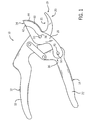
- FIG. 1 is a side plan view of an exemplary embodiment of a cutting tool having an electroless nickel layer on the metal plate.
- FIG. 2 is a partial, side perspective view of an exemplary embodiment of a cutting tool having an anvil type jaw.
- FIG. 3 is a side plan view of an exemplary embodiment of a metal plate having a forwardly extending blade and a rearwardly extending tang, with an electroless nickel layer on the blade.
- FIG. 4 is a sectional view of the metal plate illustrated in FIG. 3 along the line 4 — 4 .
- the invention relates to pivoted cutting tools having elongated members disposed for cooperative engagement upon at least one pivotable joint wherein a force applied to the handles of the tool is transmitted to the jaws engaging the work piece to be cut.
- a typical application is a pruner, grass shears, tree pruners or a branch lopper, to cut plant materials such as branches, limbs and stems.
- Other applications include scissors for cutting paper or cloth.
- the pivoted cutting tools can be manually operated or powered by a motor.
- a cutting tool 10 includes a metal plate 16 having a central aperture 38 , a forwardly extending blade 34 and a rearwardly extending tang 36 having a second aperture 40 offset from the central aperture 38 , wherein the plate 16 is coated with an electroless nickel layer 60 .
- the first elongated member 12 comprises a first handle 18 terminating at a distal end 19 by a jaw 20 .
- a second elongated member 14 comprises a second handle 22 .
- the first and second members 12 , 14 being pivotably connected to the plate 34 at the central 38 and second 40 apertures by couplers 50 , respectively, so that the blade 16 and jaw 20 pivotably move in response to pivotal movement of the first and second members 12 , 14 , about the coupler 50 in the central aperture 38 .
- the electroless nickel layer 60 is applied, as described below. In a series of baths, with the electroless nickel being in a solution of nickel sulfate (NiSO 4 ) and hypophosphate.
- NiSO 4 nickel sulfate
- the conventional method of identifying electroless nickel is by the phosphorus content, (e.g., low phosphorus 2-5%; medium phosphorus 6-9%; and high phosphorus 10-13%).
- the preferred phosphorus content of the electroless nickel layer 60 for the present invention is the medium phosphorus having a weight percent of phosphorus of about 6% to 9% as deposited on the substrate.
- the blade 34 of the metal plate 16 can be provided with a cutting edge 44 with a bevel 42 on either side or both sides of the cutting edge 44 of the blade 34 .
- the central aperture 38 is sized to receive a coupler or fastener 50 to couple the plate 16 to the first elongated member 12 near the rear end of the jaw 20 .
- the second elongated member 14 is coupled to the plate 16 by a coupler or fastener 50 engaging the second elongated member 14 and the metal plate 16 at the second aperture 40 .
- Another embodiment provides the metal plate 16 with an elongated tang 36 , as shown in FIG. 3, to which the second elongated member 14 is molded to the tang 36 .
- a second aperture 40 is configured to receive a coupler 50 that couples a lever or toggle (not shown) to the first elongated member 12 .
- the cutting tool 10 has each of the first and second elongated members 12 , 14 pivotably connected to the plate 16 at the central and second apertures, 38 , 40 respectfully.
- the couplers 50 can be a convenient fastener such as a bolt and preferably a rivet.
- the fastener or coupler 50 may also be provided with a plastic fill in the aperture which forms a threaded hole when the coupler or fastener 50 is inserted into the apertures of the plate 16 .
- the coupler 50 can be a metal or other suitable material pin molded into the elongated members 12 and 14 and aligned with a corresponding aperture in the metal plate 16 .
- the cutting tool 10 can also be provided with a jaw 20 configured as one of an anvil 21 and a blade 34 as shown in FIGS. 1 and 2.
- the jaw 20 can also be coated with an electroless nickel layer corresponding to the electroless nickel layer applied to the metal plate 16 .
- the selection of an anvil 21 or the blade 34 configuration for the jaw 20 is made at the time of manufacture and the design of which is determined for the appropriate application for which the cutting tool 10 will be used.
- the first and second elongated members 12 , 14 can be made of a moldable material such as plastic and formed as either a solid or a hollow member. It is also contemplated that the first elongated member 12 can be molded onto the jaw 20 during the fabrication process.
- first and second elongated members 12 , 14 , and the plate 16 are all fabricated from metal with the preferred embodiment having at least the first and second elongated members 12 and 14 composed of a moldable material and the plate 16 being metallic.
- the first and second members 12 , 14 are pivotably connected to a metal plate 16 having the blade 34 about a coupler 50 .
- the method comprises the steps of applying an electroless nickel coating 60 to the metal plate 16 having the blade 34 . Then positioning into a mold the metal plate 16 having the blade 34 extending forwardly and a rearwardly extending tang 36 , with the metal plate 16 having a central aperture. Then molding the first handle 18 with the forwardly extending jaw 34 and molding a second handle 22 onto the tang 36 of the metal plate 16 , then coupling the first member 12 to the metal plate 16 with the coupler 50 through the central aperture 38 .
- the electroless nickel coating 60 includes a weight percentage of phosphorus above about 6%.
- Another method includes the jaw 20 being configured as one of an anvil 21 and a blade 34 .
- the method of making a cutting tool can also include the step of grinding one of a bevel 42 and an edge 44 on the blade 34 .
- the jaw 20 of the first handle 18 can also receive a coating of electroless nickel.
- the method of manufacturing the cutting tool 10 can provide that the step applying an electroless nickel coating 60 includes the steps of cleaning the metal plate 16 in a sodium hydroxide solution, then cleaning the plate 16 with an alkaline electro cleaner and rinsing the metal plate 16 in a water bath. Then descaling the metal plate 16 in a hydrochloric acid and rinsing the metal plate 16 in a second water bath. Then cleaning the metal plate 16 with a second alkaline electro cleaner and again rinsing the metal plate 16 in a third water bath. A bath of sodium bisulfate then receives the metal blade 16 and again a fourth water bath rinsing of the metal blade 16 takes place.
- the preferred thickness of the electroless nickel is 0.0004 inches plus or minus 0.00005 inches (range 0.00035 to 0.00045 inches).
- the amount of time that the metal plate is immersed in the nickel sulfate and hypophosphate bath to obtain the desired layer of thickness depends on the temperature of the bath, the purity of the bath and other such factors which are well known to those ordinarily skilled in the relevant art. The time period may vary from about 45 minutes to about 90 minutes.
- the method of making the cutting tool 10 can also include the steps of prior to the molding the members 12 , 14 positioning two removable cores into cavities of the mold configured to form the handles so that the members are provided with hollow handles when the cores are removed from the handles after the molding process.
- cutting tools in accordance with the invention can be provided with one or more power levers with each power lever mounted on one side of each pair of first and second elongated members, thereby sandwiching the elongated members between the two power levers.
- the cutting tool can also be configured with a gearing arrangement to facilitate the transmission of force from the handles to the cutting blades.
- the cutting tool can also be configured with a pair of opposed cutting blades, as in by-pass pruners, instead of a blade cooperating with an anvil as described in one of the preferred embodiments.
Abstract
Description
Claims (6)
Priority Applications (6)
| Application Number | Priority Date | Filing Date | Title |
|---|---|---|---|
| US09/803,260 US6658967B2 (en) | 2001-03-09 | 2001-03-09 | Cutting tool with an electroless nickel coating |
| CNB028094395A CN1285451C (en) | 2001-03-09 | 2002-03-07 | Cutting tool with electroless nickel coating |
| EP02715062A EP1365895A1 (en) | 2001-03-09 | 2002-03-07 | Cutting tool with an electroless nickel coating |
| JP2002571266A JP4316239B2 (en) | 2001-03-09 | 2002-03-07 | Cutting tool with electroless nickel plating film |
| PCT/US2002/006957 WO2002072319A1 (en) | 2001-03-09 | 2002-03-07 | Cutting tool with an electroless nickel coating |
| CA2440392A CA2440392C (en) | 2001-03-09 | 2002-03-07 | Cutting tool with an electroless nickel coating |
Applications Claiming Priority (1)
| Application Number | Priority Date | Filing Date | Title |
|---|---|---|---|
| US09/803,260 US6658967B2 (en) | 2001-03-09 | 2001-03-09 | Cutting tool with an electroless nickel coating |
Publications (2)
| Publication Number | Publication Date |
|---|---|
| US20020124413A1 US20020124413A1 (en) | 2002-09-12 |
| US6658967B2 true US6658967B2 (en) | 2003-12-09 |
Family
ID=25186045
Family Applications (1)
| Application Number | Title | Priority Date | Filing Date |
|---|---|---|---|
| US09/803,260 Expired - Fee Related US6658967B2 (en) | 2001-03-09 | 2001-03-09 | Cutting tool with an electroless nickel coating |
Country Status (6)
| Country | Link |
|---|---|
| US (1) | US6658967B2 (en) |
| EP (1) | EP1365895A1 (en) |
| JP (1) | JP4316239B2 (en) |
| CN (1) | CN1285451C (en) |
| CA (1) | CA2440392C (en) |
| WO (1) | WO2002072319A1 (en) |
Cited By (6)
| Publication number | Priority date | Publication date | Assignee | Title |
|---|---|---|---|---|
| US7080455B1 (en) * | 2001-11-30 | 2006-07-25 | Ronan Tools, Inc. | Handheld kitchen scissor/knife appliance |
| US20080022535A1 (en) * | 2006-07-31 | 2008-01-31 | Scissorhand Llc | Packaging scissors |
| US20090271991A1 (en) * | 2008-05-02 | 2009-11-05 | Kett Tool Company | Powered Hand-Held Metal Cutter |
| US20100037464A1 (en) * | 2006-07-31 | 2010-02-18 | Rodney Underhill | Packaging Scissors |
| US20110192035A1 (en) * | 2010-02-09 | 2011-08-11 | Wen Ger Chen | Compound-action pruning tools |
| US9426945B2 (en) * | 2014-10-22 | 2016-08-30 | Formosa Tools Co., Ltd. | Pruning shears |
Families Citing this family (5)
| Publication number | Priority date | Publication date | Assignee | Title |
|---|---|---|---|---|
| US7509742B2 (en) * | 2002-11-19 | 2009-03-31 | Earl & Kimberly Votolato, Trustees Of The Votolato Living Trust | Safety cutting apparatus |
| ITFI20040178A1 (en) * | 2004-08-06 | 2004-11-06 | Luigi Tellini | SCISSORS WITH SLIDING CUT |
| US20130145628A1 (en) * | 2011-12-08 | 2013-06-13 | Milwaukee Electric Tool Corporation | Snips including a jaw stop |
| USD802381S1 (en) * | 2016-08-18 | 2017-11-14 | Corona Clipper, Inc. | Pruning tool |
| CN211162153U (en) * | 2017-03-24 | 2020-08-04 | 米沃奇电动工具公司 | Power shearing tool and workpiece support member and blade for power shearing tool |
Citations (44)
| Publication number | Priority date | Publication date | Assignee | Title |
|---|---|---|---|---|
| US103873A (en) * | 1870-06-07 | Improvement in fruning-knife | ||
| US164579A (en) * | 1875-06-15 | Improvement in the manufacture of pruning-shears | ||
| US1577140A (en) * | 1924-10-08 | 1926-03-16 | Mitchell Isaac Newton | Dehorning implement |
| US2368906A (en) | 1943-12-13 | 1945-02-06 | August A Westman | Wire cutter |
| US2900722A (en) | 1957-06-12 | 1959-08-25 | Weisenburger August | Shears |
| US3607353A (en) * | 1969-10-16 | 1971-09-21 | Gen Motors Corp | Surface treatment for electroplating |
| US3857724A (en) * | 1971-08-20 | 1974-12-31 | Ibm | Primer for electroless plating |
| US4007524A (en) * | 1974-12-26 | 1977-02-15 | Coats & Clark, Inc. | Cast articulated tool |
| US4143618A (en) * | 1978-04-14 | 1979-03-13 | Evo Del Vecchio | Electroless nickel plating apparatus |
| US4152164A (en) * | 1976-04-26 | 1979-05-01 | Michael Gulla | Electroless nickel plating |
| GB2081176A (en) | 1980-08-05 | 1982-02-17 | Curzons Jeremy Charles | Coated Cutting Blade |
| US4473602A (en) * | 1982-12-30 | 1984-09-25 | International Business Machines Corporation | Palladium activation of 2.5% silicon iron prior to electroless nickel plating |
| US4483711A (en) * | 1983-06-17 | 1984-11-20 | Omi International Corporation | Aqueous electroless nickel plating bath and process |
| US4695489A (en) * | 1986-07-28 | 1987-09-22 | General Electric Company | Electroless nickel plating composition and method |
| US4780342A (en) * | 1987-07-20 | 1988-10-25 | General Electric Company | Electroless nickel plating composition and method for its preparation and use |
| US4789484A (en) * | 1988-02-22 | 1988-12-06 | Occidental Chemical Corporation | Treatment of electroless nickel plating baths |
| US4858324A (en) * | 1984-01-11 | 1989-08-22 | Edge Engineering, Inc. | Knife blades and method of making said knife blades |
| US5243762A (en) * | 1991-08-30 | 1993-09-14 | Wolf-Gerate Gmbh Vertriebsgesellschaft Kg | Garden shears |
| US5258061A (en) * | 1992-11-20 | 1993-11-02 | Monsanto Company | Electroless nickel plating baths |
| EP0582411A2 (en) | 1992-07-31 | 1994-02-09 | General Electric Company | Electroless metal coatings |
| US5301431A (en) * | 1992-12-01 | 1994-04-12 | Etm Corporation | Hand-held cutting tool |
| US5338342A (en) * | 1993-05-21 | 1994-08-16 | Mallory Jr Glen O | Stabilized electroless nickel plating baths |
| US5419047A (en) * | 1993-05-14 | 1995-05-30 | Ormco Corporation | Stainless steel plier-type cutters |
| US5426857A (en) | 1992-11-30 | 1995-06-27 | Fiskars Oy Ab | Pivoted hand-held cutting tool |
| US5454165A (en) * | 1994-01-10 | 1995-10-03 | Harrow Products, Inc. | Hand-held tool with hollow handle |
| US5511314A (en) * | 1995-06-16 | 1996-04-30 | Huang; Shoei-Shin | Garden shears |
| US5570510A (en) | 1992-11-30 | 1996-11-05 | Fiskars Oy Ab | Lopper |
| US5578187A (en) | 1995-10-19 | 1996-11-26 | Enthone-Omi, Inc. | Plating process for electroless nickel on zinc die castings |
| US5621974A (en) * | 1995-09-27 | 1997-04-22 | Anthony W. Rose, Jr. | Cutting implement |
| US5636443A (en) * | 1992-11-30 | 1997-06-10 | Fiskars Oy Ab | Snips |
| RU2091502C1 (en) | 1996-10-24 | 1997-09-27 | Шевелкин Валерий Иванович | Method of chemically nickelizing steel parts |
| US5689888A (en) * | 1996-08-20 | 1997-11-25 | Fiskars Consumer Oy Ab | Variable force tool |
| US5695510A (en) * | 1992-02-20 | 1997-12-09 | Hood; Larry L. | Ultrasonic knife |
| US5697159A (en) | 1995-11-23 | 1997-12-16 | Fiskars Consumer Oy Ab | Pivoted hand tool |
| US5753304A (en) * | 1997-06-23 | 1998-05-19 | The Metal Arts Company, Inc. | Activation bath for electroless nickel plating |
| US5843538A (en) * | 1996-12-09 | 1998-12-01 | John L. Raymond | Method for electroless nickel plating of metal substrates |
| US5910340A (en) * | 1995-10-23 | 1999-06-08 | C. Uyemura & Co., Ltd. | Electroless nickel plating solution and method |
| US5950314A (en) * | 1997-08-05 | 1999-09-14 | Chang; Jung-Hsien | Step-separating shearing tool |
| US6020021A (en) | 1998-08-28 | 2000-02-01 | Mallory, Jr.; Glenn O. | Method for depositing electroless nickel phosphorus alloys |
| US6045866A (en) | 1998-08-18 | 2000-04-04 | Jin Yee Enterprise Co., Ltd. | Method of forming electroless metal plating layers on one single surface of a plastic substrate and the product thereof |
| US6106927A (en) | 1998-02-03 | 2000-08-22 | Seagate Technology, Inc. | Ultra-smooth as-deposited electroless nickel coatings |
| US6156218A (en) * | 1997-12-18 | 2000-12-05 | Japan Energy Corporation | Method of pretreatment for electroless nickel plating |
| US6245389B1 (en) * | 1996-12-27 | 2001-06-12 | Nippon Chemical Industrial Co., Ltd. | Method for circulating electroless nickel plating solution |
| US6301787B2 (en) * | 1999-08-13 | 2001-10-16 | Cooper Brands, Inc. | Shear with sliding lock mechanism |
Family Cites Families (1)
| Publication number | Priority date | Publication date | Assignee | Title |
|---|---|---|---|---|
| GB1075855A (en) * | 1963-07-22 | 1967-07-12 | Gillette Industries Ltd | Improvements in or relating to cutting instruments |
-
2001
- 2001-03-09 US US09/803,260 patent/US6658967B2/en not_active Expired - Fee Related
-
2002
- 2002-03-07 CN CNB028094395A patent/CN1285451C/en not_active Expired - Fee Related
- 2002-03-07 WO PCT/US2002/006957 patent/WO2002072319A1/en active IP Right Grant
- 2002-03-07 JP JP2002571266A patent/JP4316239B2/en not_active Expired - Fee Related
- 2002-03-07 CA CA2440392A patent/CA2440392C/en not_active Expired - Fee Related
- 2002-03-07 EP EP02715062A patent/EP1365895A1/en not_active Withdrawn
Patent Citations (45)
| Publication number | Priority date | Publication date | Assignee | Title |
|---|---|---|---|---|
| US164579A (en) * | 1875-06-15 | Improvement in the manufacture of pruning-shears | ||
| US103873A (en) * | 1870-06-07 | Improvement in fruning-knife | ||
| US1577140A (en) * | 1924-10-08 | 1926-03-16 | Mitchell Isaac Newton | Dehorning implement |
| US2368906A (en) | 1943-12-13 | 1945-02-06 | August A Westman | Wire cutter |
| US2900722A (en) | 1957-06-12 | 1959-08-25 | Weisenburger August | Shears |
| US3607353A (en) * | 1969-10-16 | 1971-09-21 | Gen Motors Corp | Surface treatment for electroplating |
| US3857724A (en) * | 1971-08-20 | 1974-12-31 | Ibm | Primer for electroless plating |
| US4007524A (en) * | 1974-12-26 | 1977-02-15 | Coats & Clark, Inc. | Cast articulated tool |
| US4152164A (en) * | 1976-04-26 | 1979-05-01 | Michael Gulla | Electroless nickel plating |
| US4143618A (en) * | 1978-04-14 | 1979-03-13 | Evo Del Vecchio | Electroless nickel plating apparatus |
| GB2081176A (en) | 1980-08-05 | 1982-02-17 | Curzons Jeremy Charles | Coated Cutting Blade |
| US4473602A (en) * | 1982-12-30 | 1984-09-25 | International Business Machines Corporation | Palladium activation of 2.5% silicon iron prior to electroless nickel plating |
| US4483711A (en) * | 1983-06-17 | 1984-11-20 | Omi International Corporation | Aqueous electroless nickel plating bath and process |
| US4858324A (en) * | 1984-01-11 | 1989-08-22 | Edge Engineering, Inc. | Knife blades and method of making said knife blades |
| US4695489A (en) * | 1986-07-28 | 1987-09-22 | General Electric Company | Electroless nickel plating composition and method |
| US4780342A (en) * | 1987-07-20 | 1988-10-25 | General Electric Company | Electroless nickel plating composition and method for its preparation and use |
| US4789484A (en) * | 1988-02-22 | 1988-12-06 | Occidental Chemical Corporation | Treatment of electroless nickel plating baths |
| US5243762A (en) * | 1991-08-30 | 1993-09-14 | Wolf-Gerate Gmbh Vertriebsgesellschaft Kg | Garden shears |
| US5695510A (en) * | 1992-02-20 | 1997-12-09 | Hood; Larry L. | Ultrasonic knife |
| US5397599A (en) * | 1992-07-31 | 1995-03-14 | General Electric Company | Preparation of electroless nickel coating having improved properties |
| EP0582411A2 (en) | 1992-07-31 | 1994-02-09 | General Electric Company | Electroless metal coatings |
| US5258061A (en) * | 1992-11-20 | 1993-11-02 | Monsanto Company | Electroless nickel plating baths |
| US5636443A (en) * | 1992-11-30 | 1997-06-10 | Fiskars Oy Ab | Snips |
| US5426857A (en) | 1992-11-30 | 1995-06-27 | Fiskars Oy Ab | Pivoted hand-held cutting tool |
| US5570510A (en) | 1992-11-30 | 1996-11-05 | Fiskars Oy Ab | Lopper |
| US5301431A (en) * | 1992-12-01 | 1994-04-12 | Etm Corporation | Hand-held cutting tool |
| US5419047A (en) * | 1993-05-14 | 1995-05-30 | Ormco Corporation | Stainless steel plier-type cutters |
| US5338342A (en) * | 1993-05-21 | 1994-08-16 | Mallory Jr Glen O | Stabilized electroless nickel plating baths |
| US5454165A (en) * | 1994-01-10 | 1995-10-03 | Harrow Products, Inc. | Hand-held tool with hollow handle |
| US5511314A (en) * | 1995-06-16 | 1996-04-30 | Huang; Shoei-Shin | Garden shears |
| US5621974A (en) * | 1995-09-27 | 1997-04-22 | Anthony W. Rose, Jr. | Cutting implement |
| US5578187A (en) | 1995-10-19 | 1996-11-26 | Enthone-Omi, Inc. | Plating process for electroless nickel on zinc die castings |
| US5910340A (en) * | 1995-10-23 | 1999-06-08 | C. Uyemura & Co., Ltd. | Electroless nickel plating solution and method |
| US5697159A (en) | 1995-11-23 | 1997-12-16 | Fiskars Consumer Oy Ab | Pivoted hand tool |
| US5689888A (en) * | 1996-08-20 | 1997-11-25 | Fiskars Consumer Oy Ab | Variable force tool |
| RU2091502C1 (en) | 1996-10-24 | 1997-09-27 | Шевелкин Валерий Иванович | Method of chemically nickelizing steel parts |
| US5843538A (en) * | 1996-12-09 | 1998-12-01 | John L. Raymond | Method for electroless nickel plating of metal substrates |
| US6245389B1 (en) * | 1996-12-27 | 2001-06-12 | Nippon Chemical Industrial Co., Ltd. | Method for circulating electroless nickel plating solution |
| US5753304A (en) * | 1997-06-23 | 1998-05-19 | The Metal Arts Company, Inc. | Activation bath for electroless nickel plating |
| US5950314A (en) * | 1997-08-05 | 1999-09-14 | Chang; Jung-Hsien | Step-separating shearing tool |
| US6156218A (en) * | 1997-12-18 | 2000-12-05 | Japan Energy Corporation | Method of pretreatment for electroless nickel plating |
| US6106927A (en) | 1998-02-03 | 2000-08-22 | Seagate Technology, Inc. | Ultra-smooth as-deposited electroless nickel coatings |
| US6045866A (en) | 1998-08-18 | 2000-04-04 | Jin Yee Enterprise Co., Ltd. | Method of forming electroless metal plating layers on one single surface of a plastic substrate and the product thereof |
| US6020021A (en) | 1998-08-28 | 2000-02-01 | Mallory, Jr.; Glenn O. | Method for depositing electroless nickel phosphorus alloys |
| US6301787B2 (en) * | 1999-08-13 | 2001-10-16 | Cooper Brands, Inc. | Shear with sliding lock mechanism |
Non-Patent Citations (2)
| Title |
|---|
| Article from Metal Finishing, Sep. 1995; Electroless Plating Process; Developing Technologies for Electroless Nickel, Palladium, and Gold, by Don Baudrand and Jon Bengston, MaDermid, Inc., Waterbury, Conn. |
| Article from PC FAB, Aug. 1985; Electroless Nickel Plating. |
Cited By (7)
| Publication number | Priority date | Publication date | Assignee | Title |
|---|---|---|---|---|
| US7080455B1 (en) * | 2001-11-30 | 2006-07-25 | Ronan Tools, Inc. | Handheld kitchen scissor/knife appliance |
| US20080022535A1 (en) * | 2006-07-31 | 2008-01-31 | Scissorhand Llc | Packaging scissors |
| US20100037464A1 (en) * | 2006-07-31 | 2010-02-18 | Rodney Underhill | Packaging Scissors |
| US20090271991A1 (en) * | 2008-05-02 | 2009-11-05 | Kett Tool Company | Powered Hand-Held Metal Cutter |
| US7971360B2 (en) * | 2008-05-02 | 2011-07-05 | Kett Tool Company | Powered hand-held metal cutter |
| US20110192035A1 (en) * | 2010-02-09 | 2011-08-11 | Wen Ger Chen | Compound-action pruning tools |
| US9426945B2 (en) * | 2014-10-22 | 2016-08-30 | Formosa Tools Co., Ltd. | Pruning shears |
Also Published As
| Publication number | Publication date |
|---|---|
| WO2002072319A1 (en) | 2002-09-19 |
| CN1285451C (en) | 2006-11-22 |
| CN1518490A (en) | 2004-08-04 |
| JP4316239B2 (en) | 2009-08-19 |
| EP1365895A1 (en) | 2003-12-03 |
| CA2440392A1 (en) | 2002-09-19 |
| CA2440392C (en) | 2010-04-27 |
| US20020124413A1 (en) | 2002-09-12 |
| JP2005506106A (en) | 2005-03-03 |
Similar Documents
| Publication | Publication Date | Title |
|---|---|---|
| MXPA03008120A (en) | Cutting tool with an electroless nickel coating. | |
| EP0746972B1 (en) | Snips | |
| CA2176094C (en) | Lopper | |
| US6658967B2 (en) | Cutting tool with an electroless nickel coating | |
| CA2210964C (en) | Variable force tool | |
| EP0673727B1 (en) | Pivoted hand-held cutting tool | |
| CN101653948B (en) | Cutting tool | |
| EP1219165B1 (en) | Power-lever cutting device | |
| JP2005506106A5 (en) | ||
| AU2002247283B2 (en) | Cutting tool with an electroless nickel coating | |
| EP1795316B1 (en) | Scissors having rustproof blades | |
| AU2002247283A1 (en) | Cutting tool with an electroless nickel coating | |
| CA2160862A1 (en) | Pivoted Tool with Foldable Handles | |
| GB2092937A (en) | A cutting device | |
| CN2048278U (en) | Multi-purpose hand grafting device | |
| JPH0469966B2 (en) |
Legal Events
| Date | Code | Title | Description |
|---|---|---|---|
| AS | Assignment |
Owner name: AQUAPORE MOISTURE SYSTEMS, WISCONSIN Free format text: ASSIGNMENT OF ASSIGNORS INTEREST;ASSIGNORS:RUTKOWSKI, ALAN;DANIO, KEN;SMITH, RON;REEL/FRAME:012718/0069 Effective date: 20010219 |
|
| AS | Assignment |
Owner name: AQUAPORE MOISTURE SYSTEMS, INC., WISCONSIN Free format text: CORRECTED ASSIGNMENT;ASSIGNORS:RUTKOWSKI, ALAN;DANIO, KEN;SMITH, RON;REEL/FRAME:012720/0085 Effective date: 20010219 |
|
| CC | Certificate of correction | ||
| FPAY | Fee payment |
Year of fee payment: 4 |
|
| FPAY | Fee payment |
Year of fee payment: 8 |
|
| REMI | Maintenance fee reminder mailed | ||
| LAPS | Lapse for failure to pay maintenance fees | ||
| STCH | Information on status: patent discontinuation |
Free format text: PATENT EXPIRED DUE TO NONPAYMENT OF MAINTENANCE FEES UNDER 37 CFR 1.362 |
|
| FP | Lapsed due to failure to pay maintenance fee |
Effective date: 20151209 |