US6658336B2 - Method and system of cooperative collision mitigation - Google Patents
Method and system of cooperative collision mitigation Download PDFInfo
- Publication number
- US6658336B2 US6658336B2 US09/853,186 US85318601A US6658336B2 US 6658336 B2 US6658336 B2 US 6658336B2 US 85318601 A US85318601 A US 85318601A US 6658336 B2 US6658336 B2 US 6658336B2
- Authority
- US
- United States
- Prior art keywords
- subject vehicle
- vehicle
- signal
- real time
- onboard
- Prior art date
- Legal status (The legal status is an assumption and is not a legal conclusion. Google has not performed a legal analysis and makes no representation as to the accuracy of the status listed.)
- Expired - Lifetime, expires
Links
Images


Classifications
-
- B—PERFORMING OPERATIONS; TRANSPORTING
- B60—VEHICLES IN GENERAL
- B60R—VEHICLES, VEHICLE FITTINGS, OR VEHICLE PARTS, NOT OTHERWISE PROVIDED FOR
- B60R21/00—Arrangements or fittings on vehicles for protecting or preventing injuries to occupants or pedestrians in case of accidents or other traffic risks
- B60R21/01—Electrical circuits for triggering passive safety arrangements, e.g. airbags, safety belt tighteners, in case of vehicle accidents or impending vehicle accidents
- B60R21/013—Electrical circuits for triggering passive safety arrangements, e.g. airbags, safety belt tighteners, in case of vehicle accidents or impending vehicle accidents including means for detecting collisions, impending collisions or roll-over
-
- G—PHYSICS
- G01—MEASURING; TESTING
- G01S—RADIO DIRECTION-FINDING; RADIO NAVIGATION; DETERMINING DISTANCE OR VELOCITY BY USE OF RADIO WAVES; LOCATING OR PRESENCE-DETECTING BY USE OF THE REFLECTION OR RERADIATION OF RADIO WAVES; ANALOGOUS ARRANGEMENTS USING OTHER WAVES
- G01S5/00—Position-fixing by co-ordinating two or more direction or position line determinations; Position-fixing by co-ordinating two or more distance determinations
- G01S5/0009—Transmission of position information to remote stations
- G01S5/0072—Transmission between mobile stations, e.g. anti-collision systems
-
- B—PERFORMING OPERATIONS; TRANSPORTING
- B60—VEHICLES IN GENERAL
- B60R—VEHICLES, VEHICLE FITTINGS, OR VEHICLE PARTS, NOT OTHERWISE PROVIDED FOR
- B60R21/00—Arrangements or fittings on vehicles for protecting or preventing injuries to occupants or pedestrians in case of accidents or other traffic risks
- B60R2021/003—Arrangements or fittings on vehicles for protecting or preventing injuries to occupants or pedestrians in case of accidents or other traffic risks characterised by occupant or pedestian
- B60R2021/0039—Body parts of the occupant or pedestrian affected by the accident
- B60R2021/0051—Knees
-
- B—PERFORMING OPERATIONS; TRANSPORTING
- B60—VEHICLES IN GENERAL
- B60R—VEHICLES, VEHICLE FITTINGS, OR VEHICLE PARTS, NOT OTHERWISE PROVIDED FOR
- B60R21/00—Arrangements or fittings on vehicles for protecting or preventing injuries to occupants or pedestrians in case of accidents or other traffic risks
- B60R21/01—Electrical circuits for triggering passive safety arrangements, e.g. airbags, safety belt tighteners, in case of vehicle accidents or impending vehicle accidents
- B60R21/013—Electrical circuits for triggering passive safety arrangements, e.g. airbags, safety belt tighteners, in case of vehicle accidents or impending vehicle accidents including means for detecting collisions, impending collisions or roll-over
- B60R21/0134—Electrical circuits for triggering passive safety arrangements, e.g. airbags, safety belt tighteners, in case of vehicle accidents or impending vehicle accidents including means for detecting collisions, impending collisions or roll-over responsive to imminent contact with an obstacle, e.g. using radar systems
-
- B—PERFORMING OPERATIONS; TRANSPORTING
- B60—VEHICLES IN GENERAL
- B60R—VEHICLES, VEHICLE FITTINGS, OR VEHICLE PARTS, NOT OTHERWISE PROVIDED FOR
- B60R21/00—Arrangements or fittings on vehicles for protecting or preventing injuries to occupants or pedestrians in case of accidents or other traffic risks
- B60R21/02—Occupant safety arrangements or fittings, e.g. crash pads
- B60R21/16—Inflatable occupant restraints or confinements designed to inflate upon impact or impending impact, e.g. air bags
- B60R21/20—Arrangements for storing inflatable members in their non-use or deflated condition; Arrangement or mounting of air bag modules or components
- B60R21/205—Arrangements for storing inflatable members in their non-use or deflated condition; Arrangement or mounting of air bag modules or components in dashboards
- B60R21/206—Arrangements for storing inflatable members in their non-use or deflated condition; Arrangement or mounting of air bag modules or components in dashboards in the lower part of dashboards, e.g. for protecting the knees
-
- G—PHYSICS
- G01—MEASURING; TESTING
- G01S—RADIO DIRECTION-FINDING; RADIO NAVIGATION; DETERMINING DISTANCE OR VELOCITY BY USE OF RADIO WAVES; LOCATING OR PRESENCE-DETECTING BY USE OF THE REFLECTION OR RERADIATION OF RADIO WAVES; ANALOGOUS ARRANGEMENTS USING OTHER WAVES
- G01S13/00—Systems using the reflection or reradiation of radio waves, e.g. radar systems; Analogous systems using reflection or reradiation of waves whose nature or wavelength is irrelevant or unspecified
- G01S13/88—Radar or analogous systems specially adapted for specific applications
- G01S13/93—Radar or analogous systems specially adapted for specific applications for anti-collision purposes
- G01S13/931—Radar or analogous systems specially adapted for specific applications for anti-collision purposes of land vehicles
- G01S2013/9316—Radar or analogous systems specially adapted for specific applications for anti-collision purposes of land vehicles combined with communication equipment with other vehicles or with base stations
-
- G—PHYSICS
- G01—MEASURING; TESTING
- G01S—RADIO DIRECTION-FINDING; RADIO NAVIGATION; DETERMINING DISTANCE OR VELOCITY BY USE OF RADIO WAVES; LOCATING OR PRESENCE-DETECTING BY USE OF THE REFLECTION OR RERADIATION OF RADIO WAVES; ANALOGOUS ARRANGEMENTS USING OTHER WAVES
- G01S13/00—Systems using the reflection or reradiation of radio waves, e.g. radar systems; Analogous systems using reflection or reradiation of waves whose nature or wavelength is irrelevant or unspecified
- G01S13/88—Radar or analogous systems specially adapted for specific applications
- G01S13/93—Radar or analogous systems specially adapted for specific applications for anti-collision purposes
- G01S13/931—Radar or analogous systems specially adapted for specific applications for anti-collision purposes of land vehicles
- G01S2013/9329—Radar or analogous systems specially adapted for specific applications for anti-collision purposes of land vehicles cooperating with reflectors or transponders
Definitions
- the present invention relates to features in a vehicle for identifying objects and, more particularly, to a system for positively identifying the nature of an object, assessing the relationship between the object and the vehicle, and deploying responsive devices according to certain situations.
- Vehicle responsive devices examples include inflatable air bag systems, seat belt systems with pyrotechnic pretensioners, bumper systems, knee bolster systems and the like. These systems can be resettable, meaning that deployment does not effect their continued operability, and non-resettable, meaning once deployed, replacement is necessary.
- Vehicle responsive devices that require activation or deployment are generally triggered by, and thus during, an actual physical impact event itself. That is, many vehicles utilize deploy systems that include impact sensors which are sensitive to abrupt changes in vehicle inertia or momentum, such as, for example, coil spring sensors, magnet-and-ball sensors, or MEMS (micro-electro-mechanical systems) devices including capacitive and/or piezoresistive accelerometer sensors, to activate or deploy vehicle responsive devices.
- impact sensors which are sensitive to abrupt changes in vehicle inertia or momentum
- MEMS micro-electro-mechanical systems
- the present invention provides a method of deploying responsive devices in a vehicle, such as an automobile, in anticipation of an impact with an object.
- a vehicle such as an automobile
- an object may include, for example, a tree, a mailbox, a sign, a fire hydrant, a post, a pole, a fence, a guardrail, a building structure, or another vehicle.
- the method basically includes the steps of using a sensor onboard a subject vehicle to identify an imminent collision between the subject vehicle and an object, directing and transmitting an elicitation signal to the object from the subject vehicle, receiving onboard the subject vehicle a response signal from the object providing information positively identifying the object, using the positive identification information to predict a severity level of the imminent collision, and in response, selectively deploying at least one responsive device onboard the subject vehicle according to the predicted severity level.
- the present invention also provides a system for deploying responsive devices in a vehicle in anticipation of a collision with an object.
- the system basically includes, first of all, a sensor attachable to a subject vehicle.
- the sensor serves to identify an imminent collision between the subject vehicle and an object.
- the system also basically includes a first computer and a second computer electrically connected to both the sensor and the first computer.
- the first computer is dedicated to processing dynamics data for the subject vehicle, and the second computer is dedicated to predicting a severity level of the imminent collision.
- the system also basically includes an antenna, attachable to the subject vehicle, and a transmitter, electrically connected between the second computer and the antenna. The transmitter serves to transmit an elicitation signal via the antenna to the object.
- the system also basically includes means for sending a response signal, from the object and to the subject vehicle, and a receiver for receiving the response signal via the antenna.
- the response signal sending means is situatable on the object, and the receiver is electrically connected between the antenna and the second computer.
- the response signal received from the object provides information positively identifying the object.
- the second computer is electrically connectable to at least one responsive device onboard the subject vehicle and is capable of using the positive identification information to predict the severity level of the imminent collision and selectively deploy each responsive device according to the predicted severity level.
- the senor is either an electromagnetic radar type sensor, a laser radar type sensor, or a pulsed infrared laser type sensor.
- the transmitter is preferably a wideband radio-frequency (RF) type transmitter capable of transmitting an elicitation signal which is an electromagnetic, modulated radio-frequency type signal having a wide frequency bandwidth.
- the response signal sending means is preferably either an active or passive transponder or at least one reflector capable of sending a predetermined response signal to the subject vehicle, thereby providing information positively identifying the object.
- the receiver preferably includes at least one filter for obtaining the positive identification information from the response signal in the form of a predetermined digital code.
- the predetermined digital code is preferably used by the second computer to look up and access object-specific data from a memory associated with the second computer. In this way, the second computer uses the object-specific data to predict the severity level of the imminent collision.
- the system may include at least one responsive device electrically connected to the second computer.
- the second computer is capable of selectively communicating a deploy signal to each responsive device according to the predicted severity level.
- the deploy signal serves as an activation signal for each responsive device which is resettable
- the deploy signal serves as an enabling signal for each responsive device which is non-resettable.
- a resettable responsive device may include, for example, a pre-tensionable seat belt, an extendable/retractable bumper, or an extendable/retractable knee bolster device.
- a non-resettable responsive device may include, for example, an inflatable airbag.
- the system may include a global positioning system (GPS) device which is attachable to the subject vehicle and electrically connected to the first computer and/or the second computer.
- GPS global positioning system
- Such a global positioning system device is useful for obtaining subject vehicle position data and digital map data therefrom for use in providing information positively identifying the object.
- the system may include a communications device attachable to the subject vehicle and electrically connected to the first computer and/or the second computer.
- the communications device preferably includes, first of all, a communications antenna, attachable to the subject vehicle, and a transmitter, electrically connected between the communications antenna and the first computer and/or the second computer.
- the communications transmitter is preferably capable of transmitting an electromagnetic polling signal via the communications antenna to the object when the imminent collision is identified to thereby determine whether the object is another vehicle having another communications device onboard.
- the communications device also preferably includes a receiver, electrically connected between the communications antenna and the first computer and/or the second computer.
- the communications receiver is preferably capable of receiving onboard the subject vehicle an electromagnetic affirmative signal via the communications antenna transmitted from the communications device onboard the object vehicle. In this way, after receiving the affirmative signal, the subject vehicle is capable of exchanging vehicle data with the object vehicle via the communications device to thereby predict the severity level of the imminent collision.
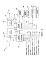
- FIG. 1 is a block diagram of a basic hardware system, according to the present invention, for deploying responsive devices in a vehicle in anticipation of a collision with an object.
- FIG. 2 is an illustration of a subject vehicle having the system of FIG. 1 onboard, wherein the subject vehicle faces potential collisions with a first object, for example, a street lamp post having a transponder, and a second object, for example, a tree having a reflector.
- a first object for example, a street lamp post having a transponder
- a second object for example, a tree having a reflector.
- FIG. 3 is a flow diagram of a basic method, according to the present invention, for deploying responsive devices in a vehicle in anticipation of a collision with an object, wherein the method is implementable with the system of FIG. 1 .
- FIG. 4 is a graph illustrating the half-power frequency bandwidth of an elicitation signal transmitted from a wideband radio-frequency transmitter included in the system of FIG. 1 .
- FIG. 5 is a graph illustrating half-power frequency bandwidths of one or more response signals over various frequency ranges, wherein each response signal is derived from one or more narrow predetermined frequency bands of the elicitation signal in FIG. 4 which are reflected from an object having one or more reflectors, such as the second object in FIG. 2 .
- FIG. 6 is a block diagram of a hardware system for deploying responsive devices in a vehicle in anticipation of a collision with an object, wherein the system uniquely includes a global positioning system (GPS) device as compared to the system of FIG. 1 .
- GPS global positioning system
- FIG. 7 is an illustration of a subject vehicle having the system of FIG. 6 onboard, wherein the subject vehicle faces a potential collision with an object, for example, a bridge abutment.
- FIG. 8 is a flow diagram of a method for deploying responsive devices in a vehicle in anticipation of a collision with an object, wherein the method is implementable with the system of FIG. 6 .
- FIG. 9 is a flow diagram of a method for deploying responsive features in a vehicle in anticipation of a collision with an object, wherein the method is implementable with the system of FIG. 6 and is an alternative to the method of FIG. 8 .
- FIG. 10 is a block diagram of a hardware system for deploying responsive devices in a vehicle in anticipation of a collision with an object, wherein the system uniquely includes a vehicle-to-vehicle communications device as compared to the system of FIG. 1 .
- FIG. 11 is an illustration of a subject vehicle having the system of FIG. 10 onboard, wherein the subject vehicle faces a potential collision with an object vehicle having a system like that of the system of FIG. 10 onboard as well.
- FIG. 12 is a flow diagram of a method for deploying responsive devices in a vehicle in anticipation of a collision with an object, wherein the method is implementable with the system of FIG. 10 .
- FIG. 13 is a block diagram of a hardware system for deploying responsive devices in a vehicle in anticipation of a collision with an object, wherein the system uniquely includes both a global positioning system device and a vehicle-to-vehicle communications device as compared to the system of FIG. 1 .
- FIG. 14 is an illustration of a subject vehicle having the system of FIG. 13 onboard, wherein the subject vehicle faces a potential collision with an object vehicle having a system like that of the system of FIG. 13 onboard as well.
- the present invention provides a method and system for deploying responsive devices in a vehicle, such as an automobile, in anticipation of a collision with an object.
- an object may include, for example, a tree, a mailbox, a sign, a fire hydrant, a post, a pole, a fence, a guardrail, a building structure, or even another vehicle.
- the present invention anticipates an imminent collision with an object so that vehicle features are activated, deployed, or pre-armed.
- the present invention also identifies the nature of the object so that collision severity can be predicted and so that individual vehicle responsive devices can be selectively deployed based on predicted collision severity.
- a detailed description of the preferred embodiments of the present invention is as follows.
- FIG. 1 is a block diagram of a basic hardware system 20 for deploying responsive devices in a vehicle in anticipation of a collision with an object.
- the hardware system 20 includes a position sensor 28 and a computer assembly 22 .
- the position sensor 28 is utilized to determine the real time position of an object relative to the vehicle.
- the sensor 28 is preferably either an electromagnetic radar type sensor, a laser radar type sensor, or merely a pulsed infrared laser type sensor.
- the sensor 28 is preferably situated at or near the lateral perimeter of the vehicle to thereby facilitate optimal line-of-sight position sensing when an object comes close to the vehicle perimeter.
- Only one position sensor 28 is illustrated in FIG. 1, it is to be understood that multiple position sensors may be situated at various different points along the perimeter of the vehicle to thereby facilitate the sensing of an object approaching from any direction.
- the computer assembly 22 includes a first computer 24 , a transmitter/receiver (T/R) device 30 , and a second computer 26 .
- the first computer 24 is dedicated to processing dynamics data for the vehicle.
- Such dynamics data may include, for example, real time data concerning the speed level, the acceleration rate, the yaw rate, the steering wheel position, the brake position, the throttle position, and/or the transmission gear position of the vehicle.
- real time data is communicated from various vehicle sensors and/or systems (not shown) to the first computer 24 via electrical conductor connections 44 , 46 , 48 , 50 , 52 , 54 , and 56 .
- the T/R device 30 of the computer assembly 22 includes both a transmitter 32 and a receiver 34 which are electrically connected to a directional-type antenna 36 .
- the transmitter 32 is preferably a wideband radio-frequency type transmitter capable of transmitting, via the antenna 36 , electromagnetic radio-frequency (RF) signals over a wide band of signal frequencies.
- the directional antenna 36 is used for both directing and transmitting an electromagnetic radio-frequency signal to the object and also for receiving a signal from the object. During transmission, the directional antenna 36 produces a substantially unidirectional radiation pattern which is directed toward the object. It is to be understood, however, that two separate antennas, one dedicated for directional transmission and one dedicated for receiving, may alternatively be used instead of the single directional antenna 36 .
- the second computer 26 of the computer assembly 22 is dedicated to predicting the severity level of any imminent collision between the vehicle and an object so that vehicle responsive devices can be selectively deployed according to the predicted severity level.
- the second computer 26 is electrically connected to the first computer 24 via electrical conductor connection 38 , electrically connected to both the transmitter 32 and the receiver 34 of the T/R device 30 via electrical conductor connection 40 , and electrically connected to the position sensor 28 via an electrical conductor connection 42 .
- deployable responsive devices onboard the vehicle may include an inflatable airbag 58 , a pre-tensionable seat belt 60 , an expandable/retractable bumper 62 , and/or an expandable/retractable knee bolster device 64 .
- Such vehicle responsive devices are electrically connected to the second computer 26 via electrical conductor connections 66 , 68 , 70 , and 72 so that each responsive device can be selectively and timely deployed as deemed necessary by the second computer 26 .
- FIG. 2 is an illustration of a subject vehicle 74 having the system 20 of FIG. 1 onboard as the subject vehicle 74 travels along a drive path 76 .
- the system 20 is attachable to and/or integrable with the structure of the subject vehicle 74 .
- the subject vehicle 74 faces potential collisions with a first object and a second object, in this particular case, a street lamppost 78 and a tree 80 .
- the system 20 in this particular case includes an active transponder 82 with an antenna 84 situated and mounted on the lamppost 78 .
- the transponder 82 is basically a small microprocessor device having a receiver circuit and a transmitter circuit electrically connected to the antenna 84 . Except for the antenna 84 , the microprocessor device of the transponder 82 is enclosed within a small protective box or container mounted on the object, in this case, the lamppost 78 .
- the microprocessor device may operate with electrical power derived from the same power source used to illuminate the lamp light in the lamp post 78 , the microprocessor device is preferably powered by rechargeable batteries which are periodically charged with an external energy collector such as, for example, a solar collector.
- an external energy collector such as, for example, a solar collector.
- the sensor 28 will sense the real time position of the lamp post 78 relative to the subject vehicle 74 and communicate real time object position data to the second computer 26 of the computer assembly 22 via connection 42 .
- relevant real time vehicle dynamics data from the first computer 24 is communicated to the second computer 26 as well via connection 38 .
- the second computer 26 uses both the real time object position data and the real time vehicle dynamics data, the second computer 26 then predicts a time until collision impact between the subject vehicle 74 and the lamp post 78 . If the predicted time until collision impact becomes equal to or less than a predetermined imminency threshold time, the second computer 26 will then deem and identify the predicted collision as an imminent collision.
- the second computer 26 initiates an elicitation or interrogation signal via connection 40 within the T/R device 30 such that the elicitation signal is directed and transmitted via the transmitter 32 and the directional antenna 36 toward the lamp post 78 .
- the elicitation signal as transmitted from the antenna 36 , is an electromagnetic, modulated radio-frequency type signal which has a wide frequency bandwidth.
- the same elicitation signal is transmitted to each object with which the subject vehicle 74 faces an imminent collision.
- the elicitation signal generally serves to prompt an object, in this case, the lamp post 78 , to provide information which will positively identify the nature of the object to the subject vehicle 74 .
- the directional nature of the antenna 36 helps ensure that the elicitation signal is not inadvertently transmitted to another object (for example, the tree 80 ) instead of, or in addition to, the lamppost 78 . In this way, only the object with which a collision is imminently anticipated is prompted for positive identification information.
- the elicitation signal is then received by the antenna 84 and the receiver circuit of the transponder 82 which is mounted on the lamppost 78 .
- a response signal is immediately initiated and transmitted from the transmitter circuit and the antenna 84 of the transponder 82 toward the subject vehicle 74 .
- the response signal, as transmitted from the antenna 84 is an electromagnetic radio-frequency type signal having a narrow, predetermined bandwidth of signal frequencies.
- This predetermined response signal generally serves to provide the subject vehicle 74 with information which positively identifies the nature of the object. More particularly, the predetermined frequency bandwidth of the response signal transmitted from the lamp post 78 serves to positively identify the first object (the lamp post 78 ) as a particular object type.
- each object will transmit different response signals having different narrow, predetermined frequency bandwidths.
- each object is differentiated and positively identified by the subject vehicle 74 according to object type by the particular frequency bandwidth of the respective response signal produced by the object.
- the response signal After being transmitted from the transponder 82 mounted on the lamppost 78 , the response signal is received by the antenna 36 and the receiver 34 of the T/R device 30 onboard the subject vehicle 74 .
- the receiver 34 includes at least one electronic filter circuit for processing the response signal to thereby obtain information positively identifying the object from the response signal in the form of a predetermined digital code.
- the predetermined digital code is communicated to the second computer 26 via connection 40 .
- object-specific object size data which is pre-stored in a memory associated with the second computer 26 is looked up and accessed by the second computer 26 by using the predetermined digital code.
- the object size data may include, for example, data relating to one or more of the width, height, depth, or mass of the object, in this particular case, the lamp post 78 .
- the second computer 26 uses and processes known subject vehicle size data, real time subject vehicle dynamics data communicated from the first computer 24 , real time object position data communicated from the sensor 28 , and the obtained object size data to predict the degree of severity or the severity level of the identified imminent collision between the subject vehicle 74 and the lamp post 78 .
- the known subject vehicle size data used in determining the severity level may include, for example, data relating to one or more of the width, height, depth, or mass of the subject vehicle 74 .
- the second computer 26 then selectively deploys at least one responsive device onboard the subject vehicle 74 according to the predicted severity level. That is, in other words, depending upon the predicted severity level, the second computer 26 then decides, for each individual responsive device, whether or not the responsive device will be deployed. In general, if the predicted severity level is high, then the second computer 26 is more likely to deploy most, if not all, of the responsive devices. On the other hand, if the predicted severity level is low, then the second computer 26 is more likely to deploy fewer responsive devices.
- the inflatable airbag 58 , the pre-tensionable seat belt 60 , the extendable/retractable bumper 62 , and the extendable/retractable knee bolster device 64 are all likely to be deployed by the second computer 26 .
- the subject vehicle 74 anticipates an imminent collision with a building structure at only 10 kilometers per hour, then only the pre-tensionable seat belt 60 and the extendable/retractable bumper 62 are likely to be deployed by the second computer 26 .
- the second computer 26 selectively communicates a deploy signal to the responsive devices 58 , 60 , 62 , and 64 via connections 66 , 68 , 70 , and 72 .
- the deploy signal serves as an activation signal for activating the responsive devices prior to collision impact.
- the deploy signal serves as a pre-arm or enabling signal for readying the activation of the responsive device upon collision impact.
- the deploy signal may instead serve as an actual activation signal for activating (in contrast to merely pre-arming or enabling) any non-resettable responsive device just prior to collision impact. If, by chance, a predicted collision fails to actually occur or if the collision is of minimal severity, the second computer 26 then communicates deactivation signals to the resettable responsive devices after a predetermined delay time has passed from the anticipated time of collision impact.
- the method of deploying responsive devices in a vehicle in anticipation of a collision with an object can be generalized to include the basic method steps 90 , 92 , 94 , 96 , and 98 set forth in the flow diagram of FIG. 3 .
- these basic steps include the step 90 of using a sensor onboard a subject vehicle to identify an imminent collision between the subject vehicle and an object, the step 92 of directing and transmitting an elicitation signal to the object from the subject vehicle, the step 94 of receiving onboard the subject vehicle a response signal from the object providing information positively identifying the object, the step 96 of using the positive identification information to predict a severity level of the imminent collision, and the step 98 of selectively deploying at least one responsive device onboard the subject vehicle according to the predicted severity level.
- the system 20 in this particular case alternatively includes, instead of the active transponder 82 situated on the lamp post 78 , a passive transponder or reflector 86 with an antenna 88 situated and mounted on the tree 80 .
- the transponder or reflector 86 is passive in the sense that no integral power source is provided therewith.
- any conventional passive transponder or reflector may be incorporated in the present invention, in the case wherein a passive transponder is used instead of a reflector, the transponder is preferably of a type which includes an inductor-capacitor (LC) circuit electrically connected to the antenna 88 .
- LC inductor-capacitor
- an elicitation signal will instead be directed and transmitted toward the tree 80 when the anticipated collision between the subject vehicle 74 and the tree 80 is identified by the second computer 26 as being imminent.
- a reflector is situated on the tree 80
- the reflector when the transmitted elicitation signal is received by the antenna 88 , the reflector merely fashions a response signal having a narrow, predetermined frequency bandwidth which is object-specific from the elicitation signal having a wide frequency bandwidth.
- the fashioned response signal comprises a reflected, narrow bandwidth portion of the elicitation signal.
- the response signal is sent via the antenna 88 to the subject vehicle 74 where the response signal is received by the antenna 36 and the receiver 34 of the T/R device 30 .
- the receiver 34 uses at least one electronic filter circuit to process the response signal to thereby obtain information positively identifying the object from the response signal in the form of a predetermined digital code. Once obtained, the predetermined digital code is then communicated to the second computer 26 for predicting collision severity and ultimately deploying vehicle responsive devices in accordance therewith.
- any suitable type of conventional transponder either active or passive, or conventional reflector may be situated on a particular object and thereby serve as a means for identifying the object to a subject vehicle pursuant to the present invention.
- an exemplary elicitation signal 100 having a signal power P 0 over a wide band of radio frequencies is graphically illustrated.
- the elicitation signal 100 has a half-power frequency bandwidth BW 0 measured from a low frequency cut-off f 0L to a high frequency cut-off f 0H .
- the reflector reflects a single, narrow, predetermined bandwidth portion of the elicitation signal 100 as a response signal back toward the subject vehicle.
- the reflector reflects only one narrow, predetermined bandwidth portion out of many different narrow frequency bands included within the bandwidth BW 0 of the elicitation signal 100 as a predetermined response signal for positively identifying the object on which the reflector is particularly situated.
- each particular reflector is only capable of reflecting one particular narrow frequency band of the elicitation signal.
- Examples of different response signals fashioned from the elicitation signal 100 by different reflectors on various different objects are graphically illustrated in FIG. 5 .
- Such exemplary response signals include a response signal 101 , a response signal 102 , a response signal 103 , and a response signal 104 .
- each response signal fashioned and reflected from the elicitation signal 100 ideally has a signal power which approaches the same signal power P 0 of the elicitation signal 100 .
- the response signal 101 has a signal power which approaches P 0 and has a half-power frequency bandwidth BW 1 measured from a low frequency cut-off f 1L to a high frequency cut-off f 1H1
- the response signal 102 has a signal power which approaches P 0 and has a half-power frequency bandwidth BW 2 measured from a low frequency cut-off f 2L to a high frequency cut-off f 2H .
- the response signal 103 has a signal power which approaches P 0 and has a half-power frequency bandwidth BW 3 measured from a low frequency cut-off f 3L to a high frequency cut-off f 3H
- the response signal 104 has a signal power which approaches P 0 and has a half-power frequency bandwidth BW 4 measured from a low frequency cut-off f 4L to a high frequency cut-off f 4H .
- the low frequency cut-off f 1L of the response signal 101 should generally be equal to or greater than the low frequency cut-off f 0L of the elicitation signal 100
- the high frequency cut-off f 4 H of the response signal 104 should generally be less than or equal to the high frequency cut-off f 0H of the elicitation signal 100 .
- each one of the particular response signals illustrated in FIG. 5 would serve to provide object-specific information for positively identifying the nature of a particular object with which a subject vehicle faces an imminent collision.
- a reflector specifically designed to send the predetermined response signal 101 may be mounted on an object which is a highway guardrail so as to positively identify the object as a guardrail-type object with the particular response signal 101 to a subject vehicle.
- another reflector specifically designed to send the predetermined response signal 102 may be mounted on an object which is a telephone pole so as to positively identify the object as a pole-type object with the particular response signal 102 to a subject vehicle.
- different response signals are used to positively identify different types or classes of objects to a subject vehicle.
- a single object may alternatively have multiple different reflectors mounted thereon at the same time which reflect different signals.
- a unique combination of different signals is used to form a composite response signal to identify each object.
- composite response signals can be encoded to thereby facilitate the positive identification of a larger number of different object types in response to an elicitation signal of a given fixed bandwidth.
- using a unique combination of different signals in the form of a composite response signal to identify an object helps prevent the misidentification of the object, which is more likely to occur when only a single band response signal is used to identify an object.
- such reflectors may either be situated separately on the object or be integrated into a single composite reflector unit on the object.
- FIG. 6 is a block diagram of an alternative hardware system 120 for deploying responsive devices in a vehicle in anticipation of a collision with an object.
- the hardware system 120 in the present embodiment includes the position sensor 28 and a computer assembly 122 .
- the computer assembly 122 in the present embodiment uniquely includes a global positioning system (GPS) device 106 in addition to the first computer 24 , the transmitter/receiver (T/R) device 30 , and the second computer 26 .
- GPS global positioning system
- the GPS device 106 is used in conjunction with a large database of detailed road and highway map information in the form of digital map data. Incorporating the GPS device 106 within the computer assembly 122 of the hardware system 120 is desirable for at least the following two reasons.
- the GPS device 106 enables a vehicle to obtain real time vehicle position data (for example, longitude and latitude) from at least one (for example, three) GPS satellite to thereby help precisely determine where the vehicle is positioned on or near a particular roadway.
- vehicle position data for example, longitude and latitude
- GPS devices utilizable with digital map data containing very detailed information concerning both the identity and position of various objects situated along or near roadways. Some of these objects may include, for example, signs, poles, fire hydrants, barriers, bridges, bridge pillars, and overpasses.
- the digital map data utilized with and/or provided by such recent GPS devices is easily updateable via remote transmissions (for example, via a cell phone) from GPS customer service centers so that detailed information concerning both the identity and position of even temporary signs or blocking structures set up during brief periods of road-related construction is available as well.
- the hardware system 120 then has additional means, as compared to the system 20 in the first embodiment, for positively identifying an object with which the vehicle anticipates an imminent collision.
- the GPS device 106 includes a receiver 108 and an antenna 110 for obtaining real time subject vehicle position data from a global positioning system satellite. As illustrated, the GPS device 106 is electrically connected to the first computer 24 via electrical conductor connection 112 and is electrically connected to the second computer 26 via electrical conductor connection 114 to thereby provide the first computer 24 and the second computer 26 with access to the real time subject vehicle position data and the digital map data. It is to be understood, however, that one of the direct connections, either 112 or 114 , from the GPS device 106 may alternatively be omitted since any subject vehicle position data and/or digital map data which is directly accessed via the one remaining direct connection can be optionally shared by the first computer 24 and the second computer 26 via the connection 38 .
- FIG. 7 is an illustration of the subject vehicle 74 alternatively having the system 120 of FIG. 6 onboard as the subject vehicle 74 travels along the drive path 76 .
- the system 120 is attachable to and/or integrable with the structure of the subject vehicle 74 .
- the subject vehicle 74 faces a potential collision with an object which, in this case, is an abutment of a bridge 118 .
- the system 120 includes a reflector 124 with an antenna 126 situated and mounted on the bridge 118 .
- the reflector 124 in the system 120 may optionally be replaced with either an active or passive transponder.
- the GPS device 106 is first activated or turned on by an operator, such as the human driver of the subject vehicle 74 , to establish electromagnetic radio-frequency communication linkage between the subject vehicle 74 and at least one (for example, three) global positioning system satellite 116 .
- an operator such as the human driver of the subject vehicle 74
- the GPS device 106 is first activated or turned on by an operator, such as the human driver of the subject vehicle 74 , to establish electromagnetic radio-frequency communication linkage between the subject vehicle 74 and at least one (for example, three) global positioning system satellite 116 .
- real time subject vehicle position data from the satellite 116 is obtained via the antenna 110 and the receiver 108 of the GPS system device 106 so that the subject vehicle position data, along with the digital map data, can be timely communicated when necessary to the first computer 24 and/or the second computer 26 via connection 112 and/or connection 114 .
- the sensor 28 will sense the real time position of the abutment of the bridge 118 relative to the subject vehicle 74 and communicate real time object position data to the second computer 26 of the computer assembly 122 via connection 42 .
- relevant real time vehicle dynamics data from the first computer 24 is communicated to the second computer 26 as well via connection 38 .
- the second computer 26 uses both the real time object position data and the real time vehicle dynamics data, the second computer 26 then predicts a time until collision impact. If the predicted time until collision impact becomes equal to or less than a predetermined imminency threshold time, the second computer 26 will then deem and identify the predicted collision as an imminent collision.
- real time object position data provided by the sensor 28 via connection 42 and both real time subject vehicle position data and digital map data provided by the GPS device 106 are used by the second computer 26 to determine whether the digital map data provides information positively identifying the object. If the object is successfully positively identified based on the digital map data provided by the GPS device 106 , then this information is used by the second computer 26 to predict the severity level of the imminent collision and selectively deploy each of the vehicle responsive devices accordingly.
- the second computer 26 initiates an elicitation signal via connection 40 so that the elicitation signal is directed and transmitted via the transmitter 32 and the antenna 36 of the T/R device 30 toward the abutment of the bridge 118 .
- the elicitation signal is then received by the reflector 124 mounted on the abutment of the bridge 118 via the antenna 126 .
- a response signal comprising a reflected, narrow, predetermined bandwidth portion of the elicitation signal is immediately sent from the reflector 124 via the antenna 126 toward the subject vehicle 74 .
- the predetermined frequency bandwidth of the response signal sent from the abutment of the bridge 118 enables the second computer 26 onboard the subject vehicle 74 to positively identify the nature of the object (the bridge 118 ) and predict the severity of the imminent collision. Once this is done, the second computer 26 then proceeds, as also generally explained earlier herein, to selectively deploy each of the vehicle responsive devices 58 , 60 , 62 , and 64 according to the predicted severity.
- the method of deploying responsive devices in a vehicle in anticipation of a collision with an object can be generalized to include the method steps 130 , 132 , 134 , 136 , 138 , 140 , 142 , 144 , and 146 as set forth in the flow diagram of FIG. 8 .
- these steps include the step 130 of establishing electromagnetic radio-frequency (RF) communication linkage between at least one global positioning system (GPS) satellite and a GPS device having digital map data situated onboard the subject vehicle to obtain real time subject vehicle position data from the satellite for use onboard the subject vehicle, the step 132 of using a sensor onboard a subject vehicle to identify an imminent collision between the subject vehicle and an object, the step 134 of using the sensor to obtain real time object position data regarding the real time position of the object with respect to the subject vehicle, and the step 136 of using the real time subject vehicle position data and the real time object position data to determine whether the digital map data provides information positively identifying the object.
- RF electromagnetic radio-frequency
- step 138 if the digital map data does not provide information positively identifying the object, then both the step 140 of directing and transmitting an elicitation signal to the object from the subject vehicle and the step 142 of receiving onboard the subject vehicle a response signal from the object providing information positively identifying the object are performed before the step 144 is performed.
- the steps 140 and 142 are skipped, and the step 144 is then performed after the step 138 .
- the step 144 of using the positive identification information to predict a severity level of the imminent collision is performed.
- the step 146 of selectively deploying at least one responsive device onboard the subject vehicle according to the predicted severity level is ultimately performed.
- the steps 132 and 134 are closely related and may alternatively be executed separately in the reverse order or even executed simultaneously such that the very same real time object position data obtained by the sensor 28 is used both for identifying an imminent collision and for trying to obtain object identification information from the digital map data.
- the particular method in FIG. 8 dictates that an elicitation signal not be transmitted to an object when the object is successfully positively identified with digital map data provided by the GPS device 106 . That is, an elicitation signal is only transmitted to an object when the object is not successfully identified with the digital map data provided by the GPS device 106 .
- the flow diagram in FIG. 9 sets forth a slightly different method of deploying responsive devices in a vehicle in anticipation of a collision with an object.
- an elicitation signal is always transmitted to an object when a collision therewith is imminent. This is so even if the object is successfully identified with the GPS device 106 .
- that information is cross-checked with identification information that is obtained from the object itself via a response signal prompted by an elicitation signal. By cross-checking object identification information in this manner, object misidentification is improved.
- the method set forth in the flow diagram of FIG. 9 generally includes the method steps 150 , 152 , 154 , 156 , 158 , 160 , 162 , 164 , 166 , and 168 . More particularly, the method includes the step 150 of establishing electromagnetic radio-frequency (RF) communication linkage between at least one global positioning system (GPS) satellite and a GPS device having digital map data situated onboard the subject vehicle to obtain real time subject vehicle position data from at least one satellite for use onboard the subject vehicle, the step 152 of using a sensor onboard the subject vehicle to identify an imminent collision between the subject vehicle and an object, the step 154 of directing and transmitting an elicitation signal to the object from the subject vehicle, the step 156 of receiving onboard the subject vehicle a response signal from the object providing information positively identifying the object, the step 158 of using the sensor to obtain real time object position data regarding the real time position of the object with respect to the subject vehicle, and the step 160 of using the real time subject vehicle position data and the real time object position data to
- step 162 if the digital map data does provide information positively identifying the object, then the step 164 of cross-checking for validation the positive identification information obtained from the digital map data with the positive identification information obtained from the object is performed before executing the step 166 and the step 168 . If, on the other hand, the digital map data does not provide information positively identifying the object, then the step 164 is skipped, and the step 166 of using the positive identification information to predict a severity level of the imminent collision and the step 168 of selectively deploying at least one responsive device onboard the subject vehicle according to the predicted severity level are thereafter performed.
- the steps 154 and 156 may be executed in parallel with the steps 158 and 160 .
- the steps 154 , 156 , 158 , and 160 may instead all be serially executed in various different serial orders as long as the step 154 is performed sometime before the step 156 and as long as the step 158 is performed sometime before the step 160 .
- the steps 152 and 158 are closely related and may alternatively be executed separately in the reverse order or executed simultaneously such that the very same real time object position data obtained by the sensor 28 is used both for identifying an imminent collision and for trying to obtain object identification information from the digital map data.
- the step 152 is most preferably performed before the step 154 .
- FIG. 10 is a block diagram of another alternative hardware system 220 for deploying responsive devices in a vehicle in anticipation of a collision with an object.
- the hardware system 220 in the present embodiment includes the position sensor 28 and a computer assembly 222 .
- the computer assembly 222 in the present embodiment uniquely includes a vehicle-to-vehicle communications device 170 in addition to the first computer 24 , the transmitter/receiver (T/R) device 30 , and the second computer 26 .
- the communications device 170 along with the remainder of the computer assembly 222 of the hardware system 220 , is situated onboard a subject vehicle.
- the communications device 170 is dedicated to communicating with an object with which an imminent collision is anticipated only when that object happens to be another vehicle (hereinafter, “object vehicle”) having a similar hardware system with a reciprocal communications device onboard.
- object vehicle having a similar hardware system with a reciprocal communications device onboard.
- both the subject vehicle and the object vehicle can transmit and receive vehicle size data and/or vehicle dynamics data to and from each other via their respective onboard communications devices in order to predict collision severity.
- the communications device 170 includes a transmitter 172 and a receiver 174 electrically connected to a communications antenna 176 .
- the communications antenna 176 is preferably a directional-type antenna.
- the communications device 170 is electrically connected to the second computer 26 via electrical conductor connection 178 and is also electrically connected to the first computer 24 via electrical conductor connection 180 .
- the connection 180 permits the transfer of subject vehicle dynamics data from the first computer 24 to the object vehicle via the communications device 170 .
- the connection 178 permits the transfer of subject vehicle size data from the second computer 26 to the object vehicle via the communications device 170 .
- connection 178 permits the transfer of electrical signals from the second computer 26 to the communications device 170 for activating and controlling the communications device 170 .
- connection 178 permits object vehicle dynamics data and/or object vehicle size data to be communicated to the second computer 26 onboard the subject vehicle as received from the object vehicle via the communications device 170 .
- FIG. 11 is an illustration of the subject vehicle 74 alternatively having the system 220 of FIG. 10 onboard as the subject vehicle 74 travels along the drive path 76 .
- the system 220 is attachable to and/or integrable with the structure of the subject vehicle 74 .
- the subject vehicle 74 faces a potential collision with an object which happens to be another vehicle, that is, an object vehicle 184 .
- the object vehicle 184 has a reciprocal communications device incorporated in a hardware system 230 onboard, similar to that of the system 220 of FIG. 10 .
- the system 230 onboard the object vehicle 184 is attachable to and/or integrable with the structure of the object vehicle 184 .
- the system 230 includes a computer assembly 182 (including a reciprocal communications device), a T/R antenna 186 , a position sensor 188 , and a communications antenna 190 , similar to those depicted in FIG. 10 with respect to the system 220 .
- the sensor 28 will sense the real time position of the object vehicle 184 relative to the subject vehicle 74 and communicate real time object vehicle position data to the second computer 26 of the computer assembly 222 via connection 42 .
- relevant real time vehicle dynamics data from the first computer 24 is communicated to the second computer 26 as well via connection 38 .
- the second computer 26 uses both the real time object position data and the real time vehicle dynamics data to predict a time until collision impact. If the predicted time until collision impact becomes equal to or less than a predetermined imminency threshold time, the second computer 26 will then deem and identify the predicted collision as an imminent collision.
- the second computer 26 then initiates a polling signal via the connection 178 to be directed and transmitted via the transmitter 172 and the communications antenna 176 of the communications device 170 as an electromagnetic signal toward the object vehicle 184 .
- the object vehicle 184 receives the polling signal via the communications antenna 190 onboard the object vehicle 184 .
- the object vehicle 184 then directs and transmits via the communications antenna 190 an electromagnetic affirmative signal back toward the subject vehicle 74 , thereby affirmatively informing the subject vehicle 74 that the object 184 is indeed another vehicle having a reciprocal communications device onboard.
- real time subject vehicle dynamics data provided by the first computer 24 and subject vehicle size data provided by the second computer 26 are transferred to the communications device 170 via the connection 180 and the connection 178 . Then, both the real time subject vehicle dynamics data and the subject vehicle size data are directed and transmitted via the transmitter 172 and the communications antenna 176 to the object vehicle 184 . Both the real time subject vehicle dynamics data and the subject vehicle size data are received by the object vehicle 184 via the communications antenna 190 onboard the object vehicle 184 .
- the object vehicle 184 transmits real time object vehicle dynamics data and object vehicle size data toward the subject vehicle 74 via the communications antenna 190 onboard the object vehicle 184 .
- the real time object vehicle dynamics data and the object vehicle size data is received by the communications device 170 onboard the subject vehicle 74 via the communications antenna 176 and the receiver 174 . Once received, the object vehicle data is transferred to the second computer 26 via the connection 178 to be processed therein.
- the real time object vehicle dynamics data, the object vehicle size data, known subject vehicle size data, and real time subject vehicle dynamics data are used by the second computer 26 to predict the severity level of the imminent collision between the subject vehicle 74 and the object vehicle 184 .
- the second computer of the computer assembly 182 onboard the object vehicle 184 uses real time subject vehicle position data provided by the sensor 188 , the real time subject vehicle dynamics data, the subject vehicle size data, real time object vehicle dynamics data, and object vehicle size data to independently predict onboard the object vehicle 184 the severity level of the imminent collision.
- the subject vehicle 74 If, upon identifying an imminent collision with an object, the subject vehicle 74 does not receive an affirmative signal in response to the polling signal, the subject vehicle 74 then assumes that the object is not another vehicle with a reciprocal communications device onboard. In such a case, the subject vehicle 74 then alternatively directs and transmits an elicitation signal to the object via the antenna 36 of the T/R device 30 as a backup means for attempting to positively identify and/or gain information from the object so that the level of collision severity can be predicted.
- the method of deploying responsive devices in a vehicle in anticipation of a collision with an object can be generalized to include the method steps 250 , 252 , 254 , 256 , 258 , 260 , 262 , 264 , 266 , 268 , 270 , and 272 as set forth in the flow diagram of FIG. 12 .
- these steps include the step 250 of using a sensor onboard the subject vehicle to identify an imminent collision between the subject vehicle and an object and the step 252 of using onboard the subject vehicle a communications device having a transmitter and a receiver to transmit a polling signal to the object to thereby determine whether the object is another vehicle having another communications device onboard.
- the step 266 of directing and transmitting an elicitation signal to the object from the subject vehicle, the step 268 of receiving onboard the subject vehicle a response signal from the object providing information positively identifying the object, and the step 270 of using the positive identification information to predict a severity level of the imminent collision are instead performed before the step 272 . Thereafter, the step 272 of selectively deploying at least one responsive device onboard the subject vehicle according to the predicted severity level is ultimately performed.
- FIG. 13 is a block diagram of still another alternative hardware system 320 for deploying responsive devices in a vehicle in anticipation of a collision with an object.
- the hardware system 320 in the present embodiment includes the position sensor 28 and a computer assembly 322 .
- the computer assembly 322 in the present embodiment uniquely includes both the GPS device 106 from the second embodiment and the communications device 170 from the third embodiment in addition to the first computer 24 , the transmitter/receiver (T/R) device 30 , and the second computer 26 .
- T/R transmitter/receiver
- FIG. 14 is an illustration of the subject vehicle 74 alternatively having the system 320 of FIG. 13 onboard as the subject vehicle 74 travels along the drive path 76 .
- the system 320 is attachable to and/or integrable with the structure of the subject vehicle 74 .
- the subject vehicle 74 faces a potential collision with an object 184 which is, at least initially, unknown to the system 320 onboard the subject vehicle 74 .
- the subject vehicle 74 With the system 320 onboard, the subject vehicle 74 thus has three different means for attempting to positively identify and/or gain information about the object so that collision severity is predicted accurately and vehicle responsive devices are deployed accordingly.
- the subject vehicle 74 may direct and transmit a polling signal to the unknown object 184 via the communications antenna 176 to determine if the object 184 is another vehicle having a reciprocal communications device onboard. If the object 184 is indeed another vehicle having a communications device onboard, then the object vehicle 184 will respond with an affirmative signal. Once the affirmative signal is received by the subject vehicle 74 , then both the subject vehicle 74 and the object vehicle 184 can exchange vehicle size data and/or vehicle dynamics data for the purpose of predicting collision severity and deploying vehicle responsive devices accordingly.
- the subject vehicle 74 may then alternatively attempt to positively identify the object 184 by seeking to obtain real time subject vehicle position data along with digital map data from the GPS device 106 and thereafter attempting to correlate any of the digital map data obtained from the GPS device 106 with object position data provided by the sensor 28 . If attempting to positively identify the object 184 with the aid of the GPS device 106 is successful, then the second computer 26 onboard the subject vehicle 74 can accurately predict collision severity and thereafter deploy responsive devices accordingly. If, however, attempting to positively identify the object 184 with the aid of the GPS device 106 is not successful, the subject vehicle 74 may then direct and transmit an elicitation signal to the object 184 via the antenna 36 .
- the subject vehicle 74 can then obtain positive identification information from the response signal in the form of a digital code. Once the digital code is obtained, the second computer 26 onboard the subject vehicle 74 can use the digital code to accurately predict the severity of the anticipated imminent collision and deploy vehicle responsive devices accordingly.
Abstract
Description
Claims (42)
Priority Applications (1)
| Application Number | Priority Date | Filing Date | Title |
|---|---|---|---|
| US09/853,186 US6658336B2 (en) | 2001-05-11 | 2001-05-11 | Method and system of cooperative collision mitigation |
Applications Claiming Priority (1)
| Application Number | Priority Date | Filing Date | Title |
|---|---|---|---|
| US09/853,186 US6658336B2 (en) | 2001-05-11 | 2001-05-11 | Method and system of cooperative collision mitigation |
Publications (2)
| Publication Number | Publication Date |
|---|---|
| US20020169533A1 US20020169533A1 (en) | 2002-11-14 |
| US6658336B2 true US6658336B2 (en) | 2003-12-02 |
Family
ID=25315298
Family Applications (1)
| Application Number | Title | Priority Date | Filing Date |
|---|---|---|---|
| US09/853,186 Expired - Lifetime US6658336B2 (en) | 2001-05-11 | 2001-05-11 | Method and system of cooperative collision mitigation |
Country Status (1)
| Country | Link |
|---|---|
| US (1) | US6658336B2 (en) |
Cited By (31)
| Publication number | Priority date | Publication date | Assignee | Title |
|---|---|---|---|---|
| US20040083824A1 (en) * | 2002-10-31 | 2004-05-06 | Nissan Motor Co., Ltd. | Seatbelt apparatus for vehicle |
| US20040100938A1 (en) * | 2002-07-31 | 2004-05-27 | Cattron-Theimeg, Inc. | System and method for wireless remote control of locomotives |
| US20040254643A1 (en) * | 2002-11-12 | 2004-12-16 | Jackson Roger P. | Articulated anterior expandable spinal fusion cage system |
| US20050033516A1 (en) * | 2003-05-30 | 2005-02-10 | Tomoya Kawasaki | Collision prediction apparatus |
| US20050036323A1 (en) * | 2003-07-01 | 2005-02-17 | Koninklijke Kpn N.V. | Method and apparatus for the housing of network elements |
| WO2006009543A1 (en) * | 2004-06-21 | 2006-01-26 | Fuller Bros., Inc. | Vehicle safety zone system |
| US20060106538A1 (en) * | 2004-11-12 | 2006-05-18 | Browne Alan L | Cooperative collision mitigation |
| US7124027B1 (en) * | 2002-07-11 | 2006-10-17 | Yazaki North America, Inc. | Vehicular collision avoidance system |
| US20070016372A1 (en) * | 2005-07-14 | 2007-01-18 | Gm Global Technology Operations, Inc. | Remote Perspective Vehicle Environment Observation System |
| US20070164896A1 (en) * | 2005-11-10 | 2007-07-19 | Hitachi, Ltd. | In-vehicle radar device and communication device |
| US20080189039A1 (en) * | 2007-02-06 | 2008-08-07 | Gm Global Technology Operations, Inc. | Collision avoidance system and method of detecting overpass locations using data fusion |
| CN100422767C (en) * | 2005-01-24 | 2008-10-01 | 株式会社电装 | Capacitance-based sensor and occupant sensing system |
| US8054181B2 (en) | 2008-04-09 | 2011-11-08 | Trimble Navigation Limited | Terrestial-signal based exclusion zone compliance |
| US8081108B2 (en) | 2008-01-07 | 2011-12-20 | Trimble Navigation Limited | Autonomous projection of global navigation satellite orbits |
| US8103438B2 (en) | 2007-09-26 | 2012-01-24 | Trimble Navigation Limited | Method and system for automatically directing traffic on a site |
| US8144000B2 (en) | 2007-09-26 | 2012-03-27 | Trimble Navigation Limited | Collision avoidance |
| US8224518B2 (en) | 2008-08-18 | 2012-07-17 | Trimble Navigation Limited | Automated recordation of crane inspection activity |
| US20130110309A1 (en) * | 2011-11-01 | 2013-05-02 | Visteon Global Technologies, Inc. | Vehicle collision avoidance and mitigation system |
| US20130127652A1 (en) * | 2010-07-16 | 2013-05-23 | Sivers Ima Ab | Method and device for continuous wave radar measurements |
| US8514058B2 (en) | 2008-08-18 | 2013-08-20 | Trimble Navigation Limited | Construction equipment component location tracking |
| US20130278440A1 (en) * | 2012-04-24 | 2013-10-24 | Zetta Research and Development, LLC - ForC Series | Anti-collision system and method using message formats containing distances |
| US20130311126A1 (en) * | 2012-04-05 | 2013-11-21 | Biodynamic Research Corporation | System Force-Deformation Modeling Apparatuses and Methods |
| US8694222B2 (en) | 2011-10-26 | 2014-04-08 | GM Global Technology Operations LLC | Collision avoidance system and method of operating the same |
| US20150151751A1 (en) * | 2013-12-04 | 2015-06-04 | Mobileye Vision Technologies Ltd. | Multi-threshold reaction zone for autonomous vehicle navigation |
| US9156167B2 (en) | 2007-05-15 | 2015-10-13 | Trimble Navigation Limited | Determining an autonomous position of a point of interest on a lifting device |
| US9415976B2 (en) * | 2012-05-10 | 2016-08-16 | Trimble Navigation Limited | Crane collision avoidance |
| US10094906B2 (en) | 2016-12-22 | 2018-10-09 | GM Global Technology Operations LLC | Vehicle positioning system using V2X, sensor, and GNSS information |
| CN108897025A (en) * | 2018-05-15 | 2018-11-27 | 艾欧创想智能科技(武汉)有限公司 | High-precision locating method, device, terminal device and computer readable storage medium |
| US10276043B2 (en) | 2016-12-22 | 2019-04-30 | GM Global Technology Operations LLC | Vehicle system using vehicle-to-infrastructure and sensor information |
| US11661055B2 (en) * | 2019-05-24 | 2023-05-30 | Preact Technologies, Inc. | Close-in collision detection combining high sample rate near-field sensors with advanced real-time parallel processing to accurately determine imminent threats and likelihood of a collision |
| US11802959B2 (en) | 2020-01-22 | 2023-10-31 | Preact Technologies, Inc. | Vehicle driver behavior data collection and reporting |
Families Citing this family (17)
| Publication number | Priority date | Publication date | Assignee | Title |
|---|---|---|---|---|
| US6166698A (en) * | 1999-02-16 | 2000-12-26 | Gentex Corporation | Rearview mirror with integrated microwave receiver |
| US20040138814A1 (en) * | 2003-01-13 | 2004-07-15 | Konkan Railway Corporation Ltd. | Anti-collision device |
| US20050090939A1 (en) * | 2003-10-27 | 2005-04-28 | Mills Aaron L. | Vision based wireless communication system |
| US7383124B1 (en) * | 2004-06-09 | 2008-06-03 | Rockwell Collins, Inc. | ADS-B broadcast monitoring system and method |
| JP2008532825A (en) * | 2005-01-24 | 2008-08-21 | ミョン ダニエル チョ | Logic for automotive airbag systems |
| US20070125589A1 (en) * | 2005-12-06 | 2007-06-07 | Murphy Morgan D | Situationally dependent vehicle structure for pedestrian protection |
| FR2896594A1 (en) * | 2006-01-24 | 2007-07-27 | Renault Sas | Movable and fixed elements e.g. pedestrian, perception method, involves introducing information related to elements of one series in perception system for fusion of images of environment established by vehicles |
| WO2009137582A1 (en) * | 2008-05-06 | 2009-11-12 | University Of Virginia Patent Foundation | System and method for minimizing occupant injury during vehicle crash events |
| CN103303142A (en) * | 2013-06-26 | 2013-09-18 | 开平市中铝实业有限公司 | Electric fire monitor system for automobile |
| GB2520493A (en) | 2013-11-20 | 2015-05-27 | Univ Coventry | Active buckling control |
| US9715257B2 (en) * | 2014-04-18 | 2017-07-25 | Apple Inc. | Active screen protection for electronic device |
| US11036239B1 (en) * | 2016-09-08 | 2021-06-15 | Janice H. Nickel | Object identification for autonomous road vehicles |
| US11591020B1 (en) | 2016-09-08 | 2023-02-28 | Janice H. Nickel | Navigation infrastructure for motor vehicles |
| DE102018104808A1 (en) * | 2018-03-02 | 2019-09-05 | Jenoptik Robot Gmbh | Method and device for estimating the height of a reflector of a vehicle |
| US20200082722A1 (en) * | 2018-09-10 | 2020-03-12 | Ben Zion Beiski | Systems and methods for improving the detection of low-electromagnetic-profile objects by vehicles |
| US10933867B2 (en) * | 2019-05-10 | 2021-03-02 | Arnouse Digital Devices Corporation | Artificial intelligence based collision avoidance system and method |
| EP3976431A4 (en) * | 2019-05-24 | 2023-08-30 | Preact Technologies, Inc. | Close-in collision detection and vehicle driver behavior data collection and reporting |
Citations (14)
| Publication number | Priority date | Publication date | Assignee | Title |
|---|---|---|---|---|
| US3097354A (en) | 1960-05-31 | 1963-07-09 | Pulse | |
| US4398172A (en) | 1981-06-08 | 1983-08-09 | Eaton Corporation | Vehicle monitor apparatus |
| US4552456A (en) * | 1981-10-31 | 1985-11-12 | Nissan Motor Company, Limited | Optical pulse radar for an automotive vehicle |
| US5008661A (en) | 1985-09-27 | 1991-04-16 | Raj Phani K | Electronic remote chemical identification system |
| US5227784A (en) * | 1990-12-10 | 1993-07-13 | Mazda Motor Corporation | System for detecting and determining range of target vehicle |
| US5235326A (en) | 1991-08-15 | 1993-08-10 | Avid Corporation | Multi-mode identification system |
| US5529138A (en) * | 1993-01-22 | 1996-06-25 | Shaw; David C. H. | Vehicle collision avoidance system |
| US5646612A (en) | 1995-02-09 | 1997-07-08 | Daewoo Electronics Co., Ltd. | Method for avoiding collision of vehicle and apparatus for performing the same |
| WO1997044216A1 (en) | 1996-05-20 | 1997-11-27 | Cho Myungeun | System for minimizing automobile collision damage and personal injury |
| US5771008A (en) | 1995-10-06 | 1998-06-23 | Toyota Jidosha Kabushiki Kaisha | Mobile unit communication control method |
| US6012008A (en) | 1997-08-26 | 2000-01-04 | Scully; Robert L. | Method and apparatus for predicting a crash and reacting thereto |
| US6028548A (en) * | 1997-01-17 | 2000-02-22 | Automotive Systems Laboratory, Inc. | Vehicle collision radar with randomized FSK waveform |
| US6085151A (en) * | 1998-01-20 | 2000-07-04 | Automotive Systems Laboratory, Inc. | Predictive collision sensing system |
| US20020135467A1 (en) * | 1999-01-12 | 2002-09-26 | Shin Koike | Positional data utilizing inter-vehicle communication method and traveling control apparatus |
-
2001
- 2001-05-11 US US09/853,186 patent/US6658336B2/en not_active Expired - Lifetime
Patent Citations (14)
| Publication number | Priority date | Publication date | Assignee | Title |
|---|---|---|---|---|
| US3097354A (en) | 1960-05-31 | 1963-07-09 | Pulse | |
| US4398172A (en) | 1981-06-08 | 1983-08-09 | Eaton Corporation | Vehicle monitor apparatus |
| US4552456A (en) * | 1981-10-31 | 1985-11-12 | Nissan Motor Company, Limited | Optical pulse radar for an automotive vehicle |
| US5008661A (en) | 1985-09-27 | 1991-04-16 | Raj Phani K | Electronic remote chemical identification system |
| US5227784A (en) * | 1990-12-10 | 1993-07-13 | Mazda Motor Corporation | System for detecting and determining range of target vehicle |
| US5235326A (en) | 1991-08-15 | 1993-08-10 | Avid Corporation | Multi-mode identification system |
| US5529138A (en) * | 1993-01-22 | 1996-06-25 | Shaw; David C. H. | Vehicle collision avoidance system |
| US5646612A (en) | 1995-02-09 | 1997-07-08 | Daewoo Electronics Co., Ltd. | Method for avoiding collision of vehicle and apparatus for performing the same |
| US5771008A (en) | 1995-10-06 | 1998-06-23 | Toyota Jidosha Kabushiki Kaisha | Mobile unit communication control method |
| WO1997044216A1 (en) | 1996-05-20 | 1997-11-27 | Cho Myungeun | System for minimizing automobile collision damage and personal injury |
| US6028548A (en) * | 1997-01-17 | 2000-02-22 | Automotive Systems Laboratory, Inc. | Vehicle collision radar with randomized FSK waveform |
| US6012008A (en) | 1997-08-26 | 2000-01-04 | Scully; Robert L. | Method and apparatus for predicting a crash and reacting thereto |
| US6085151A (en) * | 1998-01-20 | 2000-07-04 | Automotive Systems Laboratory, Inc. | Predictive collision sensing system |
| US20020135467A1 (en) * | 1999-01-12 | 2002-09-26 | Shin Koike | Positional data utilizing inter-vehicle communication method and traveling control apparatus |
Cited By (52)
| Publication number | Priority date | Publication date | Assignee | Title |
|---|---|---|---|---|
| US7124027B1 (en) * | 2002-07-11 | 2006-10-17 | Yazaki North America, Inc. | Vehicular collision avoidance system |
| US20040100938A1 (en) * | 2002-07-31 | 2004-05-27 | Cattron-Theimeg, Inc. | System and method for wireless remote control of locomotives |
| US20040114631A1 (en) * | 2002-07-31 | 2004-06-17 | Cattron-Theimeg, Inc. | System and method for wireless remote control of locomotives |
| US20040120305A1 (en) * | 2002-07-31 | 2004-06-24 | Aiken Robert C. | System and method for wireless remote control of locomotives |
| US7529201B2 (en) | 2002-07-31 | 2009-05-05 | Cattron-Theimeg, Inc. | System and method for wireless remote control of locomotives |
| US7535865B2 (en) | 2002-07-31 | 2009-05-19 | Cattron-Theimeg, Inc. | System and method for wireless remote control of locomotives |
| US7792089B2 (en) * | 2002-07-31 | 2010-09-07 | Cattron-Theimeg, Inc. | System and method for wireless remote control of locomotives |
| US20040083824A1 (en) * | 2002-10-31 | 2004-05-06 | Nissan Motor Co., Ltd. | Seatbelt apparatus for vehicle |
| US6959613B2 (en) * | 2002-10-31 | 2005-11-01 | Nissan Motor Co., Ltd. | Seatbelt apparatus for vehicle |
| US20040254643A1 (en) * | 2002-11-12 | 2004-12-16 | Jackson Roger P. | Articulated anterior expandable spinal fusion cage system |
| US7848886B2 (en) | 2003-05-30 | 2010-12-07 | Toyota Jidosha Kabushiki Kaisha | Collision prediction apparatus |
| US7848884B2 (en) | 2003-05-30 | 2010-12-07 | Toyota Jidosha Kabushiki Kaisha | Collision prediction apparatus |
| US20080269992A1 (en) * | 2003-05-30 | 2008-10-30 | Toyota Jidosha Kabushiki Kaisha | Collision prediction apparatus |
| US20050033516A1 (en) * | 2003-05-30 | 2005-02-10 | Tomoya Kawasaki | Collision prediction apparatus |
| US20080077296A1 (en) * | 2003-05-30 | 2008-03-27 | Toyota Jidosha Kabushiki Kaisha | Collision prediction apparatus |
| US20050036323A1 (en) * | 2003-07-01 | 2005-02-17 | Koninklijke Kpn N.V. | Method and apparatus for the housing of network elements |
| WO2006009543A1 (en) * | 2004-06-21 | 2006-01-26 | Fuller Bros., Inc. | Vehicle safety zone system |
| US20060106538A1 (en) * | 2004-11-12 | 2006-05-18 | Browne Alan L | Cooperative collision mitigation |
| CN100422767C (en) * | 2005-01-24 | 2008-10-01 | 株式会社电装 | Capacitance-based sensor and occupant sensing system |
| US20070016372A1 (en) * | 2005-07-14 | 2007-01-18 | Gm Global Technology Operations, Inc. | Remote Perspective Vehicle Environment Observation System |
| US20070164896A1 (en) * | 2005-11-10 | 2007-07-19 | Hitachi, Ltd. | In-vehicle radar device and communication device |
| US20080189039A1 (en) * | 2007-02-06 | 2008-08-07 | Gm Global Technology Operations, Inc. | Collision avoidance system and method of detecting overpass locations using data fusion |
| US8935086B2 (en) * | 2007-02-06 | 2015-01-13 | GM Global Technology Operations LLC | Collision avoidance system and method of detecting overpass locations using data fusion |
| US9156167B2 (en) | 2007-05-15 | 2015-10-13 | Trimble Navigation Limited | Determining an autonomous position of a point of interest on a lifting device |
| US8239125B2 (en) | 2007-09-26 | 2012-08-07 | Trimble Navigation Limited | Method and system for automatically directing traffic on a site |
| US8103438B2 (en) | 2007-09-26 | 2012-01-24 | Trimble Navigation Limited | Method and system for automatically directing traffic on a site |
| US8144000B2 (en) | 2007-09-26 | 2012-03-27 | Trimble Navigation Limited | Collision avoidance |
| US8081108B2 (en) | 2008-01-07 | 2011-12-20 | Trimble Navigation Limited | Autonomous projection of global navigation satellite orbits |
| US8054181B2 (en) | 2008-04-09 | 2011-11-08 | Trimble Navigation Limited | Terrestial-signal based exclusion zone compliance |
| US8224518B2 (en) | 2008-08-18 | 2012-07-17 | Trimble Navigation Limited | Automated recordation of crane inspection activity |
| US8514058B2 (en) | 2008-08-18 | 2013-08-20 | Trimble Navigation Limited | Construction equipment component location tracking |
| US8994583B2 (en) * | 2010-07-16 | 2015-03-31 | Sivers Ima Ab | Method and device for continuous wave radar measurements |
| US20130127652A1 (en) * | 2010-07-16 | 2013-05-23 | Sivers Ima Ab | Method and device for continuous wave radar measurements |
| US8694222B2 (en) | 2011-10-26 | 2014-04-08 | GM Global Technology Operations LLC | Collision avoidance system and method of operating the same |
| US20130110309A1 (en) * | 2011-11-01 | 2013-05-02 | Visteon Global Technologies, Inc. | Vehicle collision avoidance and mitigation system |
| US8831870B2 (en) * | 2011-11-01 | 2014-09-09 | Visteon Global Technologies, Inc. | Vehicle collision avoidance and mitigation system |
| US20130311126A1 (en) * | 2012-04-05 | 2013-11-21 | Biodynamic Research Corporation | System Force-Deformation Modeling Apparatuses and Methods |
| US9453786B2 (en) * | 2012-04-05 | 2016-09-27 | Biodynamic Research Corporation | System force-deformation modeling apparatuses and methods |
| US9470606B2 (en) * | 2012-04-05 | 2016-10-18 | Biodynamic Research Corporation | System force-deformation modeling apparatuses and methods |
| US8922391B2 (en) * | 2012-04-24 | 2014-12-30 | Zetta Research And Development Llc-Forc Series | Anti-collision system and method using message formats containing distances |
| US8860564B2 (en) * | 2012-04-24 | 2014-10-14 | Zetta Research and Development, ForC Series | Risk management in a vehicle anti-collision system |
| US20130278442A1 (en) * | 2012-04-24 | 2013-10-24 | Zetta Research And Development Llc-Forc Series | Risk management in a vehicle anti-collision system |
| US20130278440A1 (en) * | 2012-04-24 | 2013-10-24 | Zetta Research and Development, LLC - ForC Series | Anti-collision system and method using message formats containing distances |
| US9415976B2 (en) * | 2012-05-10 | 2016-08-16 | Trimble Navigation Limited | Crane collision avoidance |
| US20150151751A1 (en) * | 2013-12-04 | 2015-06-04 | Mobileye Vision Technologies Ltd. | Multi-threshold reaction zone for autonomous vehicle navigation |
| US9156473B2 (en) * | 2013-12-04 | 2015-10-13 | Mobileye Vision Technologies Ltd. | Multi-threshold reaction zone for autonomous vehicle navigation |
| US9415777B2 (en) | 2013-12-04 | 2016-08-16 | Mobileye Vision Technologies Ltd. | Multi-threshold reaction zone for autonomous vehicle navigation |
| US10094906B2 (en) | 2016-12-22 | 2018-10-09 | GM Global Technology Operations LLC | Vehicle positioning system using V2X, sensor, and GNSS information |
| US10276043B2 (en) | 2016-12-22 | 2019-04-30 | GM Global Technology Operations LLC | Vehicle system using vehicle-to-infrastructure and sensor information |
| CN108897025A (en) * | 2018-05-15 | 2018-11-27 | 艾欧创想智能科技(武汉)有限公司 | High-precision locating method, device, terminal device and computer readable storage medium |
| US11661055B2 (en) * | 2019-05-24 | 2023-05-30 | Preact Technologies, Inc. | Close-in collision detection combining high sample rate near-field sensors with advanced real-time parallel processing to accurately determine imminent threats and likelihood of a collision |
| US11802959B2 (en) | 2020-01-22 | 2023-10-31 | Preact Technologies, Inc. | Vehicle driver behavior data collection and reporting |
Also Published As
| Publication number | Publication date |
|---|---|
| US20020169533A1 (en) | 2002-11-14 |
Similar Documents
| Publication | Publication Date | Title |
|---|---|---|
| US6658336B2 (en) | Method and system of cooperative collision mitigation | |
| US20060106538A1 (en) | Cooperative collision mitigation | |
| US6876296B2 (en) | Smart license tag system | |
| US9558663B2 (en) | Animal detecting and notification method and system | |
| US8983771B2 (en) | Inter-vehicle information conveyance system and method | |
| US9652984B2 (en) | Travel information sensing and communication system | |
| EP1776599B1 (en) | Vehicle location and recovery systems | |
| US7602313B2 (en) | License plate including transponder | |
| US6472978B1 (en) | Traffic system to prevent from accidents | |
| US7489935B2 (en) | Wireless local positioning system | |
| US5490079A (en) | System for automated toll collection assisted by GPS technology | |
| US9997068B2 (en) | Method for conveying driving conditions for vehicular control | |
| EP1509429B1 (en) | Radio tracking of vehicle movements | |
| US20070164896A1 (en) | In-vehicle radar device and communication device | |
| CN108230713B (en) | Vehicle system using vehicle-to-infrastructure and sensor information | |
| US20110098877A1 (en) | Transmission of vehicle-relevent data of a vehicle via mobile communication | |
| US6246954B1 (en) | Time multiplexed global positioning system for control of traffic lights | |
| EP4047581A1 (en) | Information processing system, information processing method, and information processing device | |
| US20220410904A1 (en) | Information processing device, information processing system and information processing method | |
| JP6960956B2 (en) | On-board unit, road-to-vehicle communication system using it, and roadside unit information notification method | |
| EP3872594B1 (en) | A method, a computer program, an apparatus, a vehicle, and a network entity for predicting a deadlock situation for an automated vehicle | |
| US20170039406A1 (en) | Extinguisher with tracking device and monitoring installation for vehicles | |
| Agbolade | Radio frequency speed bumps for near-zero speed zone control in Nigeria | |
| JP3008802B2 (en) | Vehicle communication device | |
| JP2004282591A (en) | On-vehicle communication terminal for narrow-band communication |
Legal Events
| Date | Code | Title | Description |
|---|---|---|---|
| AS | Assignment |
Owner name: GENERAL MOTORS CORPORATION, MICHIGAN Free format text: ASSIGNMENT OF ASSIGNORS INTEREST;ASSIGNORS:BROWNE, ALAN LAMPE;WOOD, FRANCIS D.;ALTAN, OSMAN D.;REEL/FRAME:011816/0326;SIGNING DATES FROM 20010425 TO 20010430 |
|
| STCF | Information on status: patent grant |
Free format text: PATENTED CASE |
|
| FPAY | Fee payment |
Year of fee payment: 4 |
|
| CC | Certificate of correction | ||
| AS | Assignment |
Owner name: GM GLOBAL TECHNOLOGY OPERATIONS, INC., MICHIGAN Free format text: ASSIGNMENT OF ASSIGNORS INTEREST;ASSIGNOR:GENERAL MOTORS CORPORATION;REEL/FRAME:022117/0047 Effective date: 20050119 Owner name: GM GLOBAL TECHNOLOGY OPERATIONS, INC.,MICHIGAN Free format text: ASSIGNMENT OF ASSIGNORS INTEREST;ASSIGNOR:GENERAL MOTORS CORPORATION;REEL/FRAME:022117/0047 Effective date: 20050119 |
|
| AS | Assignment |
Owner name: UNITED STATES DEPARTMENT OF THE TREASURY, DISTRICT Free format text: SECURITY AGREEMENT;ASSIGNOR:GM GLOBAL TECHNOLOGY OPERATIONS, INC.;REEL/FRAME:022201/0501 Effective date: 20081231 |
|
| AS | Assignment |
Owner name: CITICORP USA, INC. AS AGENT FOR HEDGE PRIORITY SEC Free format text: SECURITY AGREEMENT;ASSIGNOR:GM GLOBAL TECHNOLOGY OPERATIONS, INC.;REEL/FRAME:022556/0013 Effective date: 20090409 Owner name: CITICORP USA, INC. AS AGENT FOR BANK PRIORITY SECU Free format text: SECURITY AGREEMENT;ASSIGNOR:GM GLOBAL TECHNOLOGY OPERATIONS, INC.;REEL/FRAME:022556/0013 Effective date: 20090409 |
|
| AS | Assignment |
Owner name: GM GLOBAL TECHNOLOGY OPERATIONS, INC., MICHIGAN Free format text: RELEASE BY SECURED PARTY;ASSIGNOR:UNITED STATES DEPARTMENT OF THE TREASURY;REEL/FRAME:023238/0015 Effective date: 20090709 |
|
| XAS | Not any more in us assignment database |
Free format text: RELEASE BY SECURED PARTY;ASSIGNOR:UNITED STATES DEPARTMENT OF THE TREASURY;REEL/FRAME:023124/0383 |
|
| AS | Assignment |
Owner name: GM GLOBAL TECHNOLOGY OPERATIONS, INC., MICHIGAN Free format text: RELEASE BY SECURED PARTY;ASSIGNORS:CITICORP USA, INC. AS AGENT FOR BANK PRIORITY SECURED PARTIES;CITICORP USA, INC. AS AGENT FOR HEDGE PRIORITY SECURED PARTIES;REEL/FRAME:023127/0326 Effective date: 20090814 |
|
| AS | Assignment |
Owner name: UNITED STATES DEPARTMENT OF THE TREASURY, DISTRICT Free format text: SECURITY AGREEMENT;ASSIGNOR:GM GLOBAL TECHNOLOGY OPERATIONS, INC.;REEL/FRAME:023155/0922 Effective date: 20090710 |
|
| AS | Assignment |
Owner name: UAW RETIREE MEDICAL BENEFITS TRUST, MICHIGAN Free format text: SECURITY AGREEMENT;ASSIGNOR:GM GLOBAL TECHNOLOGY OPERATIONS, INC.;REEL/FRAME:023161/0864 Effective date: 20090710 |
|
| AS | Assignment |
Owner name: GM GLOBAL TECHNOLOGY OPERATIONS, INC., MICHIGAN Free format text: RELEASE BY SECURED PARTY;ASSIGNOR:UNITED STATES DEPARTMENT OF THE TREASURY;REEL/FRAME:025245/0273 Effective date: 20100420 Owner name: GM GLOBAL TECHNOLOGY OPERATIONS, INC., MICHIGAN Free format text: RELEASE BY SECURED PARTY;ASSIGNOR:UAW RETIREE MEDICAL BENEFITS TRUST;REEL/FRAME:025311/0680 Effective date: 20101026 |
|
| AS | Assignment |
Owner name: WILMINGTON TRUST COMPANY, DELAWARE Free format text: SECURITY AGREEMENT;ASSIGNOR:GM GLOBAL TECHNOLOGY OPERATIONS, INC.;REEL/FRAME:025327/0222 Effective date: 20101027 |
|
| AS | Assignment |
Owner name: GM GLOBAL TECHNOLOGY OPERATIONS LLC, MICHIGAN Free format text: CHANGE OF NAME;ASSIGNOR:GM GLOBAL TECHNOLOGY OPERATIONS, INC.;REEL/FRAME:025780/0795 Effective date: 20101202 |
|
| FPAY | Fee payment |
Year of fee payment: 8 |
|
| AS | Assignment |
Owner name: GM GLOBAL TECHNOLOGY OPERATIONS LLC, MICHIGAN Free format text: RELEASE BY SECURED PARTY;ASSIGNOR:WILMINGTON TRUST COMPANY;REEL/FRAME:034183/0680 Effective date: 20141017 |
|
| FPAY | Fee payment |
Year of fee payment: 12 |