US6657121B2 - Thermal management system and method for electronics system - Google Patents
Thermal management system and method for electronics system Download PDFInfo
- Publication number
- US6657121B2 US6657121B2 US10/180,166 US18016602A US6657121B2 US 6657121 B2 US6657121 B2 US 6657121B2 US 18016602 A US18016602 A US 18016602A US 6657121 B2 US6657121 B2 US 6657121B2
- Authority
- US
- United States
- Prior art keywords
- thermal
- thermal energy
- heat
- bus
- management system
- Prior art date
- Legal status (The legal status is an assumption and is not a legal conclusion. Google has not performed a legal analysis and makes no representation as to the accuracy of the status listed.)
- Expired - Lifetime
Links
- 238000000034 method Methods 0.000 title abstract description 8
- 230000007480 spreading Effects 0.000 claims abstract description 24
- 238000003892 spreading Methods 0.000 claims abstract description 24
- 230000004907 flux Effects 0.000 claims description 14
- 239000000463 material Substances 0.000 claims description 9
- 239000004020 conductor Substances 0.000 claims description 7
- RYGMFSIKBFXOCR-UHFFFAOYSA-N Copper Chemical compound [Cu] RYGMFSIKBFXOCR-UHFFFAOYSA-N 0.000 claims description 6
- 238000004891 communication Methods 0.000 claims description 5
- 229910010271 silicon carbide Inorganic materials 0.000 claims description 5
- 230000007246 mechanism Effects 0.000 claims description 4
- 229910052751 metal Inorganic materials 0.000 claims description 3
- 239000002184 metal Substances 0.000 claims description 3
- 239000011800 void material Substances 0.000 claims description 2
- XUIMIQQOPSSXEZ-UHFFFAOYSA-N Silicon Chemical compound [Si] XUIMIQQOPSSXEZ-UHFFFAOYSA-N 0.000 claims 1
- 230000008020 evaporation Effects 0.000 claims 1
- 238000001704 evaporation Methods 0.000 claims 1
- 239000004065 semiconductor Substances 0.000 abstract description 16
- 230000008878 coupling Effects 0.000 abstract description 6
- 238000010168 coupling process Methods 0.000 abstract description 6
- 238000005859 coupling reaction Methods 0.000 abstract description 6
- 238000012546 transfer Methods 0.000 description 12
- 238000001816 cooling Methods 0.000 description 9
- QGZKDVFQNNGYKY-UHFFFAOYSA-N Ammonia Chemical compound N QGZKDVFQNNGYKY-UHFFFAOYSA-N 0.000 description 6
- 238000005057 refrigeration Methods 0.000 description 6
- 230000017525 heat dissipation Effects 0.000 description 5
- 239000012530 fluid Substances 0.000 description 4
- 229910021529 ammonia Inorganic materials 0.000 description 3
- 238000013461 design Methods 0.000 description 3
- 238000005516 engineering process Methods 0.000 description 3
- 239000004519 grease Substances 0.000 description 3
- 239000007788 liquid Substances 0.000 description 3
- 230000009467 reduction Effects 0.000 description 3
- XLYOFNOQVPJJNP-UHFFFAOYSA-N water Substances O XLYOFNOQVPJJNP-UHFFFAOYSA-N 0.000 description 3
- 230000002411 adverse Effects 0.000 description 2
- 239000003570 air Substances 0.000 description 2
- 238000013459 approach Methods 0.000 description 2
- 229910052802 copper Inorganic materials 0.000 description 2
- 239000010949 copper Substances 0.000 description 2
- 230000000694 effects Effects 0.000 description 2
- 230000020169 heat generation Effects 0.000 description 2
- 238000004806 packaging method and process Methods 0.000 description 2
- 238000010248 power generation Methods 0.000 description 2
- 238000007789 sealing Methods 0.000 description 2
- 230000000930 thermomechanical effect Effects 0.000 description 2
- 229910052782 aluminium Inorganic materials 0.000 description 1
- XAGFODPZIPBFFR-UHFFFAOYSA-N aluminium Chemical compound [Al] XAGFODPZIPBFFR-UHFFFAOYSA-N 0.000 description 1
- 239000012080 ambient air Substances 0.000 description 1
- 238000005219 brazing Methods 0.000 description 1
- 150000001875 compounds Chemical class 0.000 description 1
- 238000010276 construction Methods 0.000 description 1
- 238000011161 development Methods 0.000 description 1
- 238000009826 distribution Methods 0.000 description 1
- 230000007613 environmental effect Effects 0.000 description 1
- 230000010354 integration Effects 0.000 description 1
- 238000005304 joining Methods 0.000 description 1
- 230000004807 localization Effects 0.000 description 1
- 229910044991 metal oxide Inorganic materials 0.000 description 1
- 150000004706 metal oxides Chemical class 0.000 description 1
- 238000012986 modification Methods 0.000 description 1
- 230000004048 modification Effects 0.000 description 1
- 238000005457 optimization Methods 0.000 description 1
- 238000013021 overheating Methods 0.000 description 1
- 230000008569 process Effects 0.000 description 1
- 238000012545 processing Methods 0.000 description 1
- 229910000679 solder Inorganic materials 0.000 description 1
Images


Classifications
-
- H—ELECTRICITY
- H05—ELECTRIC TECHNIQUES NOT OTHERWISE PROVIDED FOR
- H05K—PRINTED CIRCUITS; CASINGS OR CONSTRUCTIONAL DETAILS OF ELECTRIC APPARATUS; MANUFACTURE OF ASSEMBLAGES OF ELECTRICAL COMPONENTS
- H05K7/00—Constructional details common to different types of electric apparatus
- H05K7/20—Modifications to facilitate cooling, ventilating, or heating
- H05K7/20536—Modifications to facilitate cooling, ventilating, or heating for racks or cabinets of standardised dimensions, e.g. electronic racks for aircraft or telecommunication equipment
- H05K7/20663—Liquid coolant with phase change, e.g. heat pipes
- H05K7/20681—Liquid coolant with phase change, e.g. heat pipes within cabinets for removing heat from sub-racks
-
- H—ELECTRICITY
- H05—ELECTRIC TECHNIQUES NOT OTHERWISE PROVIDED FOR
- H05K—PRINTED CIRCUITS; CASINGS OR CONSTRUCTIONAL DETAILS OF ELECTRIC APPARATUS; MANUFACTURE OF ASSEMBLAGES OF ELECTRICAL COMPONENTS
- H05K7/00—Constructional details common to different types of electric apparatus
- H05K7/20—Modifications to facilitate cooling, ventilating, or heating
- H05K7/20709—Modifications to facilitate cooling, ventilating, or heating for server racks or cabinets; for data centers, e.g. 19-inch computer racks
- H05K7/208—Liquid cooling with phase change
- H05K7/20809—Liquid cooling with phase change within server blades for removing heat from heat source
-
- H—ELECTRICITY
- H05—ELECTRIC TECHNIQUES NOT OTHERWISE PROVIDED FOR
- H05K—PRINTED CIRCUITS; CASINGS OR CONSTRUCTIONAL DETAILS OF ELECTRIC APPARATUS; MANUFACTURE OF ASSEMBLAGES OF ELECTRICAL COMPONENTS
- H05K7/00—Constructional details common to different types of electric apparatus
- H05K7/20—Modifications to facilitate cooling, ventilating, or heating
- H05K7/20709—Modifications to facilitate cooling, ventilating, or heating for server racks or cabinets; for data centers, e.g. 19-inch computer racks
- H05K7/208—Liquid cooling with phase change
- H05K7/20818—Liquid cooling with phase change within cabinets for removing heat from server blades
Definitions
- the present invention generally relates to the management of thermal energy generated by electronic systems, and more particularly to a packaging scheme for efficiently and cost effectively routing and controlling the thermal energy generated by various components of an electronic system.
- thermal budget that is available for the design of the cooling devices/systems needed to manage the heat fluxes generated by the various electronic devices in the system.
- delta-T thermal resistances
- the present invention provides a thermal energy management system comprising a heat spreading device that is operatively engaged with at least one semiconductor chip.
- a thermal bus is operatively engaged with the heat spreading device so as to transport thermal energy from the heat spreading device to a heat sink.
- the heat spreading device comprises a heat pipe and a thermal bus is provided that comprises a loop thermosyphon.
- a second thermal bus is operatively engaged with the first thermal bus so as to transport thermal energy from the first thermal bus to a heat sink.
- the second thermal bus may also comprise a loop thermosyphon.
- a method of managing thermal energy in an electronic system includes spreading thermal energy generated by one or more devices over a surface that is relatively larger than the devices, thermally coupling an evaporator portion of a loop thermosyphon to the surface, and thermally coupling a condensing portion of the loop thermosyphon to a thermal energy sink, e.g., a second loop thermosyphon, convection fin, or cold plate.
- a thermal energy sink e.g., a second loop thermosyphon, convection fin, or cold plate.
- FIG. 1 is a perspective view, partially in phantom, of a typical electronics system including a thermal management system formed in accordance with one embodiment of the present invention
- FIG. 2 is a perspective view of a typical electronics subsystem incorporating the thermal management system of the present invention
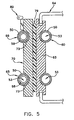
- FIG. 3 is a perspective, broken-away view of a portion of the electronics subsystem shown in FIG. 2;
- FIG. 4 is a cross-sectional view, as taken along line 4 — 4 in FIG. 3, of a thermal bus, evaporator plate, heat pipe, and heat generating electronic component;
- FIG. 5 is a cross-sectional view, as taken along line 5 — 5 in FIG. 2, of a thermal bus to thermal bus interface.
- thermal energy management system 5 that may be implemented in a functioning system of electronic components and/or subsystems e.g., a 1-U server 8 .
- Thermal energy management system 5 generally comprises a hierarchical scheme of thermal management components that are operatively engaged with individual heat generating components or groups of such components that form server 8 .
- the thermal management components are substantially only thermally driven, i.e., passive heat transfer devices that have no moving parts and require no external power for their operation.
- thermal energy management system 5 comprises a planar heat pipe 12 arranged in thermal communication with a thermal bus 14 for transporting thermal energy away from individual heat generating devices 15 , 16 as well as, clusters of such devices within the electronic system. More particularly, planar heat pipe 12 is sized and shaped so as to spread the thermal energy generated by at least one semiconductor device 15 , 16 that is arranged in intimate thermal engagement with planar heat pipe 12 within server 8 . Often, one or more semiconductor devices 15 , 16 e.g., microprocessors, voltage regulators, power supplies, etc., are mounted within the same region of the electronics system.
- semiconductor devices 15 , 16 e.g., microprocessors, voltage regulators, power supplies, etc.
- planar heat pipe 12 comprises a vapor chamber 25 that is defined between a top wall 28 and a bottom wall 31 , and extends transversely and longitudinally throughout planar heat pipe 12 .
- top wall 28 and bottom wall 31 comprise substantially uniform thickness sheets of a thermally conductive material, and are spaced-apart by about 2.0 (mm) to about 4.0 (mm) so as to form the void space within heat pipe 12 that defines vapor chamber 25 .
- Top wall 28 preferably comprises a substantially planer inner surface 36 .
- Bottom wall 31 of planar heat pipe 12 is also substantially planar, and comprises an integrally formed layer of wicking material, or wick 39 .
- sintered copper powder or felt metal wick structure having an average thickness of about 0.5 mm to 2.0 mm is positioned over substantially all of the inner surface of bottom wall 31 so as to form wick 39 .
- wick materials such as, aluminum-silicon-carbide or copper-silicon-carbide may be used with equal effect.
- Vapor chamber 25 is created by the attachment of top wall 28 and bottom wall 31 , along their common edges which are then hermetically sealed at their joining interface 41 .
- a two-phase vaporizable liquid e.g., ammonia or freon not shown
- Heat pipe 12 is formed by drawing a partial vacuum within vapor chamber 25 and injecting the working fluid just prior to final hermetic sealing of the common edges of top wall 28 and bottom wall 31 .
- planar heat pipe 12 (including top wall 28 and bottom wall 31 ) may be made of copper or copper-silicon-carbide with water, ammonia, or freon generally chosen as the two-phase vaporizable liquid.
- thermal bus 14 comprises a loop-thermosyphon 42 that is thermally engaged with planar heat pipe 12 so as to bus thermal energy from planar heat pipe 12 to a thermal energy sink or heat sink 43 , e.g., a cold plate or convection cooled fin stack.
- thermal energy sink or heat sink 43 e.g., a cold plate or convection cooled fin stack.
- terms such as “bus, buses, or busing” mean to transport or otherwise transfer thermal energy in a directed manner from one location to another location, e.g., from a high heat flux portion to a lower heat flux portion of a rack/chassis assembly 46 that structurally supports a plurality of servers 8 .
- Loop thermosyphon 42 comprises a closed tube 50 that is formed from a substantially uniform thickness, thermally conductive material (e.g., copper, aluminum, or the like) having a continuous internal passageway 53 .
- At least an evaporator portion 55 of tube 50 includes an integrally formed wicking layer 58 of sintered copper powder or metal felt, having an average thickness of about 0.5 mm to 2.0 mm. Wicking layer 58 is continuously disposed over substantially all of the inner surface of tube 50 at evaporator portion 55 .
- a condensing portion 60 of tube 50 is positioned in spaced away relation to evaporator portion 55 , and often arranged in intimate thermal contact with a wall 63 of a support chassis 64 of server 8 .
- Loop thermosyphon 42 is maintained in position within server 8 by means of simple fasteners, e.g., screws and brackets, so that it may be disassembled from the underlying electronic system and components so that they may be serviced without need for time consuming and error prone reassembly of the system.
- a two-phase vaporizable liquid e.g., ammonia, water, freon or the like, not shown
- Loop thermosyphon 42 may be formed by drawing a partial vacuum within tube 50 and injecting the working fluid just prior to final hermetic sealing of the tube.
- Condensing portion 60 of tube 50 may or may not include an integrally formed wicking layer 58 .
- the evaporator portions 65 of one or more additional loop-thermosyphons 66 may be located on the outer surface 67 of wall 63 so as to (i) receive thermal energy from condensing portion 60 of loop-thermosyphon 42 , via thermal conduction through wall 63 , and (ii) bus that thermal energy to other lower heat flux regions of a rack/chassis assembly 46 .
- Loop thermosyphon 66 is also maintained in position within on chassis 46 by means of simple fasteners, e.g., screws and brackets, so that it may be quickly disassembled from the underlying electronic system and chassis for servicing.
- Evaporator plates 70 provide a physical and thermal interface between top wall 28 of planar heat pipe 12 and evaporator portion 55 of loop-thermosyphon 42 , and between wall 63 and evaporator portion 65 of loop-thermosyphon 66 . More particularly, evaporator plate 70 is formed from a substantially uniform thickness sheet of a thermally conductive material, and is preferably substantially planar. It is sized and shaped to cover a portion of top wall 28 of planar heat pipe 12 , or the portion of wall 63 adjacent to evaporator portions 65 of loop-thermosyphon 66 .
- bottom wall 31 may be either permanently bonded to heat generating devices 15 , 16 , or a thermal grease or other heat transfer material may be disposed at the thermal interface 72 between evaporator 70 and heat generating devices 15 , 16 .
- At least two grooves 73 are formed in a top surface 76 of evaporator plate 70 so as to receive and cradle evaporator portion 55 of loop-thermosyphon 42 , or evaporator portion 65 of loop-thermosyphon 66 .
- a thermal grease or other heat transfer material may be diposed at the thermal busing interface 79 between evaporator portion 65 of loop-thermosyphon 66 and condensing portion 60 of loop thermosyphon 42 , and wall 63 .
- a mechanical locking mechanism 80 may also be employed to help force evaporator plate 70 into intimate thermal engagement and communication with wall 63 so as to enhance heat transfer across this thermo-mechanical interface.
- thermal management system and method 5 of the present invention was used for cooling four McKinley processors in a 1-U rack mount system.
- Each processor generates one hundred and thirty watts of thermal energy
- each power supply generates forty-five watts
- each central processing unit generates one hundred and seventy-five watts, so that each server yields about seven hundred watts of thermal energy, with a total power output for the rack equal to about twenty-nine thousand four hundred watts.
- the allowable thermal resistance is based upon a T c max equal to about eighty-five degrees centigrade. Assuming an allowable ambient temperature of thirty-five degrees centigrade, the rate of power generation from the overall system, that is allowable to remain within specifications, is about 0.38 watts per degree centigrade.
- the thermal busing path from server 8 to heat sink 43 starts at first thermal interface 74 between the case or package containing the first McKinley processor 15 and bottom wall 31 of heat pipe 12 (FIG. 4 ).
- heat pipe 12 extends across both the McKinley processor 15 and its associated power supply pod 16 so as to spread thermal energy over an area larger than the area of at least one of these heat generating components, i.e., heat pipe heat spreader 12 preferably comprises a larger area than processor 15 and its associated power supply pod 16 .
- Heat is transferred across first thermal interface 74 to bottom wall 31 , through vapor chamber 25 , to top wall 28 .
- Heat pipe 12 is often permanently attached to at least processor 15 by e.g., solder or brazing, such that first thermal interface 74 permanently attaches processor 15 to the outer surface of bottom wall 31 .
- a second thermal interface 72 is provided between the bottom surface of evaporator 70 and the outer surface of top wall 28 .
- a thermal grease or other heat transfer material may be disposed at thermal interface 72 .
- Evaporator portion 55 of flexible loop thermosyphon 42 is then assembled to each evaporator plate 70 via placing tube 50 into grooves 73 on top surfaces 76 .
- Flexible loop thermosyphon 42 is maintained in place on evaporators 70 by means of simple fasteners that are easily removed for servicing.
- the heat transferred from heat pipes 12 actually creates a series of multiple evaporator portions 55 along the length of flexible loop thermosyphon 42 .
- This interface between heat pipe 12 and flexible loop thermosyphon 42 is thus a detachable thermal joint so as to allow for the replacement of processor 15 and power supply module 16 .
- Flexible loop thermosyphon 42 transfers all the heat generated by the four McKinley processors 15 and four associated power supplies 16 to side wall 63 of the 1-U server 8 which provides lower thermal flux region for condenser portion 60 of flexible loop thermosyphon 42 (FIG. 5 ).
- a third thermal interface 79 is provided between wall 63 and an evaporator plate 70 that is cradling evaporator portion 65 of loop thermosyphon 66 (FIG. 5 ).
- This interface is often enhanced by use of a cam-type mechanical locking mechanism 80 that aids in forcing evaporator plate 70 into intimate thermal engagement and communication with wall 63 so as to enhance heat transfer across this thermo-mechanical interface.
- loop thermosyphon 66 transfers the heat to the top of rack 46 where it can be dissipated to a large air-cooled heat sink 43 , or coupled to a re-circulated water or refrigeration cooled heat sink.
- the details of the condenser integration are not shown in the various figures, however, a simple tube-in-fin type heat exchanger could easily be integrated.
- thermal management system and method 5 yielded an overall system temperature rise is 21.6 degrees C., which corresponds to a thermal resistance of 0.166 degrees C./watt based on the 130 watts processor power. Assuming a 50 degrees C. allowable case to ambient temperature rise leaves 28.4 degrees C. available to dissipate the transferred heat from the condenser of loop thermosyphon 66 to the ambient air.
- thermal energy management system comprising a hierarchical scheme of thermal management components that are operatively engaged with individual components or groups of components that form an electronic system is provided which avoids all of the aforementioned problems associated with prior art systems for managing thermal energy generated by electronic systems.
- a thermal energy management system incorporates discrete heat spreading technologies at the semiconductor device and semiconductor device package that enables the package temperature to increase without overheating at the junction level while incorporating a thermal bus for transporting or otherwise transferring thermal energy in a directed manner from one location to another location, e.g., from the high heat flux portion of a semiconductor to a lower heat flux portion of an external heat sink.
- thermal energy management system is provided that is easily disassembled from the underlying electronic system and components so that they may be serviced without need for time consuming and error prone reassembly.
Abstract
Description
Claims (16)
Priority Applications (3)
| Application Number | Priority Date | Filing Date | Title |
|---|---|---|---|
| US10/180,166 US6657121B2 (en) | 2001-06-27 | 2002-06-26 | Thermal management system and method for electronics system |
| US10/658,828 US6972365B2 (en) | 2001-06-27 | 2003-09-09 | Thermal management system and method for electronics system |
| US11/218,747 US7071408B2 (en) | 2001-06-27 | 2005-09-02 | Thermal management system and method for electronics system |
Applications Claiming Priority (2)
| Application Number | Priority Date | Filing Date | Title |
|---|---|---|---|
| US30122401P | 2001-06-27 | 2001-06-27 | |
| US10/180,166 US6657121B2 (en) | 2001-06-27 | 2002-06-26 | Thermal management system and method for electronics system |
Related Child Applications (1)
| Application Number | Title | Priority Date | Filing Date |
|---|---|---|---|
| US10/658,828 Continuation US6972365B2 (en) | 2001-06-27 | 2003-09-09 | Thermal management system and method for electronics system |
Publications (2)
| Publication Number | Publication Date |
|---|---|
| US20030000721A1 US20030000721A1 (en) | 2003-01-02 |
| US6657121B2 true US6657121B2 (en) | 2003-12-02 |
Family
ID=26876055
Family Applications (3)
| Application Number | Title | Priority Date | Filing Date |
|---|---|---|---|
| US10/180,166 Expired - Lifetime US6657121B2 (en) | 2001-06-27 | 2002-06-26 | Thermal management system and method for electronics system |
| US10/658,828 Expired - Lifetime US6972365B2 (en) | 2001-06-27 | 2003-09-09 | Thermal management system and method for electronics system |
| US11/218,747 Expired - Fee Related US7071408B2 (en) | 2001-06-27 | 2005-09-02 | Thermal management system and method for electronics system |
Family Applications After (2)
| Application Number | Title | Priority Date | Filing Date |
|---|---|---|---|
| US10/658,828 Expired - Lifetime US6972365B2 (en) | 2001-06-27 | 2003-09-09 | Thermal management system and method for electronics system |
| US11/218,747 Expired - Fee Related US7071408B2 (en) | 2001-06-27 | 2005-09-02 | Thermal management system and method for electronics system |
Country Status (1)
| Country | Link |
|---|---|
| US (3) | US6657121B2 (en) |
Cited By (76)
| Publication number | Priority date | Publication date | Assignee | Title |
|---|---|---|---|---|
| US20040037045A1 (en) * | 2002-08-14 | 2004-02-26 | Phillips Alfred L. | Thermal bus for electronics systems |
| US20040045730A1 (en) * | 2001-06-27 | 2004-03-11 | Garner Scott D. | Thermal management system and method for electronics system |
| US20040080907A1 (en) * | 2002-10-25 | 2004-04-29 | Belady Christian L. | Cell thermal connector |
| US20040221604A1 (en) * | 2003-02-14 | 2004-11-11 | Shigemi Ota | Liquid cooling system for a rack-mount server system |
| US20050024831A1 (en) * | 2003-07-28 | 2005-02-03 | Phillips Alfred L. | Flexible loop thermosyphon |
| US6856037B2 (en) * | 2001-11-26 | 2005-02-15 | Sony Corporation | Method and apparatus for converting dissipated heat to work energy |
| US20050068728A1 (en) * | 2003-09-30 | 2005-03-31 | International Business Machines Corporation | Thermal dissipation assembly and fabrication method for electronics drawer of a multiple-drawer electronics rack |
| US20050083657A1 (en) * | 2003-10-18 | 2005-04-21 | Qnx Cooling Systems, Inc. | Liquid cooling system |
| US20050128710A1 (en) * | 2003-12-15 | 2005-06-16 | Beiteimal Abdlmonem H. | Cooling system for electronic components |
| US20050133200A1 (en) * | 2003-12-17 | 2005-06-23 | Malone Christopher G. | One or more heat exchanger components in major part operably locatable outside computer chassis |
| US20050168938A1 (en) * | 2004-02-03 | 2005-08-04 | Bash Cullen E. | Small form factor cooling system |
| US20050211418A1 (en) * | 2002-11-01 | 2005-09-29 | Cooligy, Inc. | Method and apparatus for efficient vertical fluid delivery for cooling a heat producing device |
| US20060056154A1 (en) * | 2004-09-15 | 2006-03-16 | International Business Machines Corporation | Apparatus including a thermal bus on a circuit board for cooling components on a daughter card releasably attached to the circuit board |
| US20060087810A1 (en) * | 2004-10-25 | 2006-04-27 | Uwe Rockenfeller | Apparatus and method for cooling electronics and computer components with managed and prioritized directional air flow heat rejection |
| US20060187639A1 (en) * | 2005-02-23 | 2006-08-24 | Lytron, Inc. | Electronic component cooling and interface system |
| US20060278372A1 (en) * | 2005-06-08 | 2006-12-14 | Cheng-Tien Lai | Heat dissipation device |
| US20070095507A1 (en) * | 2005-09-16 | 2007-05-03 | University Of Cincinnati | Silicon mems based two-phase heat transfer device |
| US20070201204A1 (en) * | 2006-02-16 | 2007-08-30 | Girish Upadhya | Liquid cooling loops for server applications |
| US20070206937A1 (en) * | 2006-03-01 | 2007-09-06 | Nikon Corporation | Focus adjustment device, imaging device and focus adjustment method |
| US7269005B2 (en) * | 2003-11-21 | 2007-09-11 | Intel Corporation | Pumped loop cooling with remote heat exchanger and display cooling |
| US20070227709A1 (en) * | 2006-03-30 | 2007-10-04 | Girish Upadhya | Multi device cooling |
| US20070256957A1 (en) * | 2006-05-06 | 2007-11-08 | Schroff Gmbh | Sub-rack with housing for receiving plug-in modules |
| US20070256815A1 (en) * | 2006-05-04 | 2007-11-08 | Cooligy, Inc. | Scalable liquid cooling system with modular radiators |
| US20070274044A1 (en) * | 2003-07-30 | 2007-11-29 | Kermi Gmbh | Cooling Device For an Electronic Component, Especially for a Microprocessor |
| US20080013283A1 (en) * | 2006-07-17 | 2008-01-17 | Gilbert Gary L | Mechanism for cooling electronic components |
| US20080043442A1 (en) * | 2006-08-16 | 2008-02-21 | Strickland Travis C | Computer system with thermal conduction |
| US20080128113A1 (en) * | 2005-06-30 | 2008-06-05 | Kabushiki Kaisha Toshiba | Cooling device and electronic apparatus |
| US20080210405A1 (en) * | 2002-11-01 | 2008-09-04 | Madhav Datta | Fabrication of high surface to volume ratio structures and their integration in microheat exchangers for liquid cooling systems |
| US20080212265A1 (en) * | 2007-01-23 | 2008-09-04 | Paul Mazura | Switchgear Cabinet for Accommodating Electronic Plug-In Modules with a Heat Exchanger |
| US20080259566A1 (en) * | 2007-04-16 | 2008-10-23 | Stephen Samuel Fried | Efficiently cool data centers and electronic enclosures using loop heat pipes |
| US20090027856A1 (en) * | 2007-07-26 | 2009-01-29 | Mccoy Scott | Blade cooling system using wet and dry heat sinks |
| US7515418B2 (en) | 2005-09-26 | 2009-04-07 | Curtiss-Wright Controls, Inc. | Adjustable height liquid cooler in liquid flow through plate |
| WO2009072698A1 (en) * | 2007-12-06 | 2009-06-11 | Electronics And Telecommunications Research Institute | The flat plate type micro heat spreading device |
| US20090154104A1 (en) * | 2007-12-14 | 2009-06-18 | Yoshihiro Kondo | Cooling Device and Electronic Apparatus Using the Same |
| US20090161312A1 (en) * | 2006-02-16 | 2009-06-25 | Liebert Corporation | Liquid cooling systems for server applications |
| US20090159240A1 (en) * | 2007-12-20 | 2009-06-25 | Chung-Jun Chu | Mobile cooling structure and machine case having the same |
| US20100073863A1 (en) * | 2008-09-24 | 2010-03-25 | Hitachi, Ltd. | Electronic apparatus |
| US20100132404A1 (en) * | 2008-12-03 | 2010-06-03 | Progressive Cooling Solutions, Inc. | Bonds and method for forming bonds for a two-phase cooling apparatus |
| US20100241278A1 (en) * | 2008-02-28 | 2010-09-23 | International Business Machines Coporation | Variable flow computer cooling system for a data center and method of operation |
| US20100243210A1 (en) * | 2003-03-20 | 2010-09-30 | Rosenfeld John H | Capillary assisted loop thermosiphon apparatus |
| US7806168B2 (en) | 2002-11-01 | 2010-10-05 | Cooligy Inc | Optimal spreader system, device and method for fluid cooled micro-scaled heat exchange |
| US20100277864A1 (en) * | 2009-04-29 | 2010-11-04 | Tozer Robert | Cooling |
| US20100296250A1 (en) * | 2009-05-22 | 2010-11-25 | Chiu-Mao Huang | Heat dissipation device for communication chassis |
| US20100313590A1 (en) * | 2009-06-10 | 2010-12-16 | International Business Machines Corporation | Liquid-cooled cooling apparatus, electronics rack and methods of fabrication thereof |
| US20100326627A1 (en) * | 2009-06-30 | 2010-12-30 | Schon Steven G | Microelectronics cooling system |
| US20100328892A1 (en) * | 2009-06-25 | 2010-12-30 | Sun Microsystems, Inc. | Molded heat sink and method of making same |
| US20110019359A1 (en) * | 2009-07-23 | 2011-01-27 | Toshiba Tec Kabushiki Kaisha | Electronic apparatus |
| US20110026219A1 (en) * | 2009-07-31 | 2011-02-03 | Hewlett-Packard Development Company, L.P. | Heat transfer systems and methods |
| US20110085296A1 (en) * | 2009-10-14 | 2011-04-14 | Brandon Rubenstein | Cooling System For A Computer Blade |
| US20120039036A1 (en) * | 2009-10-30 | 2012-02-16 | Krause Michael R | Thermal bus bar for a blade enclosure |
| US20120057296A1 (en) * | 2010-09-08 | 2012-03-08 | Getac Technology Corporation | Host apparatus with waterproof function and heat dissipation module thereof |
| US8188595B2 (en) | 2008-08-13 | 2012-05-29 | Progressive Cooling Solutions, Inc. | Two-phase cooling for light-emitting devices |
| US20120250259A1 (en) * | 2011-04-01 | 2012-10-04 | Academia Sinica | Cooling system for an electronic rack |
| US20130077232A1 (en) * | 2011-09-22 | 2013-03-28 | Panduit Corp. | Thermal management infrastructure for it equipment in a cabinet |
| US8464781B2 (en) | 2002-11-01 | 2013-06-18 | Cooligy Inc. | Cooling systems incorporating heat exchangers and thermoelectric layers |
| US8602092B2 (en) | 2003-07-23 | 2013-12-10 | Cooligy, Inc. | Pump and fan control concepts in a cooling system |
| US8792226B2 (en) | 2012-03-27 | 2014-07-29 | General Electric Company | Heat transfer system for use with electrical devices and method of operating the same |
| US8893513B2 (en) | 2012-05-07 | 2014-11-25 | Phononic Device, Inc. | Thermoelectric heat exchanger component including protective heat spreading lid and optimal thermal interface resistance |
| US20140362531A1 (en) * | 2011-04-01 | 2014-12-11 | Academia Sinica | Cooling system for an electronic rack |
| US20150062821A1 (en) * | 2012-03-22 | 2015-03-05 | Nec Corporation | Cooling Structure for Electronic Circuit Board, and Electronic Device Using the Same |
| US8991194B2 (en) | 2012-05-07 | 2015-03-31 | Phononic Devices, Inc. | Parallel thermoelectric heat exchange systems |
| US20150114602A1 (en) * | 2011-05-06 | 2015-04-30 | International Business Machines Corporation | Fabricating cooled electronic system with liquid-cooled cold plate and thermal spreader |
| US9036353B2 (en) | 2012-11-26 | 2015-05-19 | Northrop Grumman Systems Corporation | Flexible thermal interface for electronics |
| US20160018139A1 (en) * | 2014-07-21 | 2016-01-21 | Phononic Devices, Inc. | Integration of thermosiphon tubing into accept heat exchanger |
| US20160128234A1 (en) * | 2014-10-30 | 2016-05-05 | Fujitsu Limited | Cooling device and electronic apparatus |
| US9593871B2 (en) | 2014-07-21 | 2017-03-14 | Phononic Devices, Inc. | Systems and methods for operating a thermoelectric module to increase efficiency |
| US10206310B2 (en) * | 2017-04-07 | 2019-02-12 | Toyota Motor Engineering & Manufacturing North America, Inc. | Electronics assemblies incorporating three-dimensional heat flow structures |
| US10209003B2 (en) | 2012-02-21 | 2019-02-19 | Thermal Corp. | Electronics cabinet and rack cooling system and method |
| US10349561B2 (en) | 2016-04-15 | 2019-07-09 | Google Llc | Cooling electronic devices in a data center |
| US10448543B2 (en) | 2015-05-04 | 2019-10-15 | Google Llc | Cooling electronic devices in a data center |
| US10458683B2 (en) | 2014-07-21 | 2019-10-29 | Phononic, Inc. | Systems and methods for mitigating heat rejection limitations of a thermoelectric module |
| US10462935B2 (en) | 2015-06-23 | 2019-10-29 | Google Llc | Cooling electronic devices in a data center |
| US20210204449A1 (en) * | 2019-12-27 | 2021-07-01 | Baidu Usa Llc | Cooling design for electronics enclosure |
| US20210307208A1 (en) * | 2020-03-26 | 2021-09-30 | Baidu Usa Llc | Modular design of blind mate interface for liquid cooling |
| US11596086B2 (en) * | 2019-03-27 | 2023-02-28 | Lenovo Enterprise Solutions (Singapore) Pte. Ltd. | Systems and methods for cooling an electronic device via interface of a heat-transfer conduit of the electronic device to a cold plate assembly |
| US20230225080A1 (en) * | 2022-01-12 | 2023-07-13 | Arista Networks, Inc. | Hybrid heatsink system |
Families Citing this family (60)
| Publication number | Priority date | Publication date | Assignee | Title |
|---|---|---|---|---|
| DE10355598B3 (en) * | 2003-11-28 | 2005-05-25 | Fujitsu Siemens Computers Gmbh | Cooling device for electrical component of computer system with heat-generating components has spring compressed when electrical component fitted in computer system so contacts are connected to thermally connect heat conducting tubes |
| JP4371210B2 (en) * | 2003-12-05 | 2009-11-25 | 日本電気株式会社 | Electronic unit and heat dissipation structure |
| DE102004054337B4 (en) * | 2004-11-09 | 2007-01-11 | Rittal Res Electronic Systems Gmbh & Co. Kg | cooling arrangement |
| US7345877B2 (en) * | 2005-01-06 | 2008-03-18 | The Boeing Company | Cooling apparatus, system, and associated method |
| US20060162897A1 (en) * | 2005-01-27 | 2006-07-27 | Amita Technologies Inc. Ltd. | Heat dissipating apparatus |
| US7719837B2 (en) * | 2005-08-22 | 2010-05-18 | Shan Ping Wu | Method and apparatus for cooling a blade server |
| US7372705B1 (en) * | 2006-02-01 | 2008-05-13 | Cisco Technology, Inc. | Portable data routing device and method of use |
| US7518868B2 (en) * | 2006-02-28 | 2009-04-14 | International Business Machines Corporation | Apparatus, system, and method for efficient heat dissipation |
| US20070297136A1 (en) * | 2006-06-23 | 2007-12-27 | Sun Micosystems, Inc. | Modular liquid cooling of electronic components while preserving data center integrity |
| US20080087406A1 (en) * | 2006-10-13 | 2008-04-17 | The Boeing Company | Cooling system and associated method for planar pulsating heat pipe |
| TW200821801A (en) * | 2006-11-08 | 2008-05-16 | Jiun-Guang Luo | Case having phase-change heat dissipating device |
| US7805955B2 (en) * | 2006-12-30 | 2010-10-05 | Intel Corporation | Using refrigeration and heat pipe for electronics cooling applications |
| US7460367B2 (en) * | 2007-03-05 | 2008-12-02 | Tracewell Systems, Inc. | Method and system for dissipating thermal energy from conduction-cooled circuit card assemblies which employ remote heat sinks and heat pipe technology |
| US8651172B2 (en) | 2007-03-22 | 2014-02-18 | Raytheon Company | System and method for separating components of a fluid coolant for cooling a structure |
| US8422218B2 (en) * | 2007-04-16 | 2013-04-16 | Stephen Samuel Fried | Liquid cooled condensers for loop heat pipe like enclosure cooling |
| US8950468B2 (en) * | 2007-05-11 | 2015-02-10 | The Boeing Company | Cooling system for aerospace vehicle components |
| US7885063B2 (en) * | 2007-08-20 | 2011-02-08 | Nvidia Corporation | Circuit board heat exchanger carrier system and method |
| US7921655B2 (en) * | 2007-09-21 | 2011-04-12 | Raytheon Company | Topping cycle for a sub-ambient cooling system |
| US7907409B2 (en) * | 2008-03-25 | 2011-03-15 | Raytheon Company | Systems and methods for cooling a computing component in a computing rack |
| US7626820B1 (en) * | 2008-05-15 | 2009-12-01 | Sun Microsystems, Inc. | Thermal transfer technique using heat pipes with integral rack rails |
| US20090323276A1 (en) * | 2008-06-25 | 2009-12-31 | Mongia Rajiv K | High performance spreader for lid cooling applications |
| DE102008044645B3 (en) * | 2008-08-27 | 2010-02-18 | Airbus Deutschland Gmbh | An aircraft signal computer system comprising a plurality of modular signal processor units |
| CN101902895A (en) * | 2009-05-27 | 2010-12-01 | 鸿富锦精密工业(深圳)有限公司 | Cooling system |
| US9036351B2 (en) * | 2009-06-22 | 2015-05-19 | Xyber Technologies, Llc | Passive cooling system and method for electronics devices |
| US8582298B2 (en) * | 2009-06-22 | 2013-11-12 | Xyber Technologies | Passive cooling enclosure system and method for electronics devices |
| CN101645714B (en) * | 2009-09-03 | 2012-12-12 | 华为技术有限公司 | Remote end radio frequency module |
| CN102696103B (en) * | 2009-09-28 | 2016-01-13 | Abb研究有限公司 | For the refrigerating module of cool electronic component |
| US20110079376A1 (en) * | 2009-10-03 | 2011-04-07 | Wolverine Tube, Inc. | Cold plate with pins |
| WO2011053213A1 (en) * | 2009-11-02 | 2011-05-05 | Telefonaktiebolaget Lm Ericsson (Publ) | Passive cabinet cooling |
| EP2517541B1 (en) | 2009-12-23 | 2019-12-11 | Telefonaktiebolaget LM Ericsson (publ) | Heat conducting mounting structure, method and radio base station housing arrangement for mounting electronic modules |
| WO2011119926A2 (en) | 2010-03-25 | 2011-09-29 | Porreca Paul J | Conduction-cooled apparatus and methods of forming said apparatus |
| US8077460B1 (en) | 2010-07-19 | 2011-12-13 | Toyota Motor Engineering & Manufacturing North America, Inc. | Heat exchanger fluid distribution manifolds and power electronics modules incorporating the same |
| US8659896B2 (en) | 2010-09-13 | 2014-02-25 | Toyota Motor Engineering & Manufacturing North America, Inc. | Cooling apparatuses and power electronics modules |
| US8199505B2 (en) | 2010-09-13 | 2012-06-12 | Toyota Motor Engineering & Manufacturing Norh America, Inc. | Jet impingement heat exchanger apparatuses and power electronics modules |
| FR2965141B1 (en) * | 2010-09-22 | 2016-07-29 | Airbus Operations Sas | ELECTRONIC CARD WITH DIPHASIC COOLING, ELECTRONIC EQUIPMENT INCORPORATING SUCH CARD AND AIRCRAFT INCORPORATING SUCH EQUIPMENT |
| US8644020B2 (en) * | 2010-12-01 | 2014-02-04 | Google Inc. | Cooling heat-generating electronics |
| FR2969379B1 (en) * | 2010-12-17 | 2013-02-15 | Thales Sa | COOLING AN ELECTRONIC EQUIPMENT |
| US8427832B2 (en) | 2011-01-05 | 2013-04-23 | Toyota Motor Engineering & Manufacturing North America, Inc. | Cold plate assemblies and power electronics modules |
| US8391008B2 (en) | 2011-02-17 | 2013-03-05 | Toyota Motor Engineering & Manufacturing North America, Inc. | Power electronics modules and power electronics module assemblies |
| US8482919B2 (en) | 2011-04-11 | 2013-07-09 | Toyota Motor Engineering & Manufacturing North America, Inc. | Power electronics card assemblies, power electronics modules, and power electronics devices |
| US20120279683A1 (en) * | 2011-05-05 | 2012-11-08 | Alcatel-Lucent Usa Inc. | Cooling apparatus for communications platforms |
| DE102011082352A1 (en) * | 2011-09-08 | 2013-03-14 | Siemens Aktiengesellschaft | Apparatus and method for cooling a device |
| US9746248B2 (en) | 2011-10-18 | 2017-08-29 | Thermal Corp. | Heat pipe having a wick with a hybrid profile |
| JP5824662B2 (en) * | 2011-11-08 | 2015-11-25 | パナソニックIpマネジメント株式会社 | Cooling device for cooling rack servers and data center equipped with the same |
| US8811014B2 (en) | 2011-12-29 | 2014-08-19 | General Electric Company | Heat exchange assembly and methods of assembling same |
| US8780559B2 (en) | 2011-12-29 | 2014-07-15 | General Electric Company | Heat exchange assembly for use with electrical devices and methods of assembling an electrical device |
| US8643173B1 (en) | 2013-01-04 | 2014-02-04 | Toyota Motor Engineering & Manufacturing North America, Inc. | Cooling apparatuses and power electronics modules with single-phase and two-phase surface enhancement features |
| US9131631B2 (en) | 2013-08-08 | 2015-09-08 | Toyota Motor Engineering & Manufacturing North America, Inc. | Jet impingement cooling apparatuses having enhanced heat transfer assemblies |
| US9398731B1 (en) | 2014-09-23 | 2016-07-19 | Google Inc. | Cooling electronic devices in a data center |
| US20180027696A1 (en) * | 2015-03-24 | 2018-01-25 | Hewlett Packard Enterprise Development Lp | Liquid cooling with a cooling chamber |
| US10619940B2 (en) * | 2015-07-28 | 2020-04-14 | The Boeing Company | Heat exchanger systems and methods |
| US10345874B1 (en) | 2016-05-02 | 2019-07-09 | Juniper Networks, Inc | Apparatus, system, and method for decreasing heat migration in ganged heatsinks |
| CN107664454A (en) * | 2016-07-29 | 2018-02-06 | 双鸿科技股份有限公司 | The electronic installation of this loop hot-pipe of loop hot-pipe and application |
| JP2018133349A (en) * | 2017-02-13 | 2018-08-23 | 富士通株式会社 | Electronic device and cooling method of the same |
| US10591964B1 (en) * | 2017-02-14 | 2020-03-17 | Juniper Networks, Inc | Apparatus, system, and method for improved heat spreading in heatsinks |
| EP3723463B1 (en) | 2019-04-10 | 2023-03-01 | ABB Schweiz AG | Heat exchanger with integrated two-phase heat spreader |
| WO2021111387A1 (en) * | 2019-12-05 | 2021-06-10 | Provides Metalmeccanica S.R.L. | Cooling system of electronic systems, in particular for data centre |
| IT201900023076A1 (en) * | 2019-12-05 | 2021-06-05 | Provides Metalmeccanica S R L | COOLING SYSTEM FOR DATA CENTER |
| CN111918528B (en) * | 2020-07-27 | 2021-09-03 | 东风汽车集团有限公司 | Motor controller with laminated busbar heat dissipation structure |
| EP4181642A1 (en) * | 2021-11-16 | 2023-05-17 | JJ Cooling Innovation Sàrl | Cooling system for electronic component racks |
Citations (33)
| Publication number | Priority date | Publication date | Assignee | Title |
|---|---|---|---|---|
| US3317798A (en) | 1966-04-13 | 1967-05-02 | Ibm | Cooling electrical apparatus |
| US3387648A (en) | 1967-02-23 | 1968-06-11 | Navy Usa | Cabinet enclosed recirculation cooling system carried on extensible chassis mountingelectronic modules |
| US4323914A (en) | 1979-02-01 | 1982-04-06 | International Business Machines Corporation | Heat transfer structure for integrated circuit package |
| US4366526A (en) | 1980-10-03 | 1982-12-28 | Grumman Aerospace Corporation | Heat-pipe cooled electronic circuit card |
| US4393663A (en) * | 1981-04-13 | 1983-07-19 | Gas Research Institute | Two-phase thermosyphon heater |
| US4602679A (en) | 1982-03-22 | 1986-07-29 | Grumman Aerospace Corporation | Capillary-pumped heat transfer panel and system |
| JPS61250491A (en) * | 1985-04-25 | 1986-11-07 | Takasago Thermal Eng Co Ltd | Heat pipe |
| US4793405A (en) | 1985-12-13 | 1988-12-27 | Hasler Ag. | Process and apparatus for dissipating the heat loss of at least one assembly of electrical elements |
| US4931905A (en) | 1989-01-17 | 1990-06-05 | Grumman Aerospace Corporation | Heat pipe cooled electronic circuit card |
| US4941530A (en) | 1989-01-13 | 1990-07-17 | Sundstrand Corporation | Enhanced air fin cooling arrangement for a hermetically sealed modular electronic cold plate utilizing reflux cooling |
| US4949164A (en) | 1987-07-10 | 1990-08-14 | Hitachi, Ltd. | Semiconductor cooling apparatus and cooling method thereof |
| US5003376A (en) | 1989-03-28 | 1991-03-26 | Coriolis Corporation | Cooling of large high power semi-conductors |
| US5063475A (en) | 1990-03-19 | 1991-11-05 | International Business Machines Corporation | Multileveled electronic assembly with cooling means |
| US5077601A (en) | 1988-09-09 | 1991-12-31 | Hitachi, Ltd. | Cooling system for cooling an electronic device and heat radiation fin for use in the cooling system |
| US5150278A (en) | 1991-04-16 | 1992-09-22 | J. E. Thomas Specialties Limited | Finned housing |
| US5203399A (en) | 1990-05-16 | 1993-04-20 | Kabushiki Kaisha Toshiba | Heat transfer apparatus |
| JPH05328230A (en) | 1992-05-27 | 1993-12-10 | Matsushita Electric Ind Co Ltd | Noise reduction circuit |
| US5283715A (en) | 1992-09-29 | 1994-02-01 | International Business Machines, Inc. | Integrated heat pipe and circuit board structure |
| US5329425A (en) | 1991-02-25 | 1994-07-12 | Alcatel N.V. | Cooling system |
| US5361188A (en) | 1990-10-24 | 1994-11-01 | Hitachi Ltd. | Cooling apparatus of electronic equipment |
| US5513071A (en) | 1994-11-28 | 1996-04-30 | Philips Electronics North America Corporation | Electronics housing with improved heat rejection |
| US5587880A (en) | 1995-06-28 | 1996-12-24 | Aavid Laboratories, Inc. | Computer cooling system operable under the force of gravity in first orientation and against the force of gravity in second orientation |
| JPH0969595A (en) | 1995-09-01 | 1997-03-11 | Yaskawa Electric Corp | Electronic equipment unit |
| US5613552A (en) | 1994-07-13 | 1997-03-25 | Nippondenso Co., Ltd. | Cooling apparatus using boiling and condensing refrigerant |
| US5713413A (en) | 1994-12-28 | 1998-02-03 | Nippondenso Co., Ltd. | Cooling apparatus using boiling and condensing refrigerant |
| US5720338A (en) | 1993-09-10 | 1998-02-24 | Aavid Laboratories, Inc. | Two-phase thermal bag component cooler |
| US5761037A (en) * | 1996-02-12 | 1998-06-02 | International Business Machines Corporation | Orientation independent evaporator |
| US5822187A (en) * | 1996-10-25 | 1998-10-13 | Thermal Corp. | Heat pipes inserted into first and second parallel holes in a block for transferring heat between hinged devices |
| US5832989A (en) | 1996-03-14 | 1998-11-10 | Denso Corporation | Cooling apparatus using boiling and condensing refrigerant |
| US5836381A (en) | 1994-07-19 | 1998-11-17 | Nippondenso Co., Ltd. | Cooling apparatus using boiling and condensing refrigerant |
| US5953930A (en) * | 1998-03-31 | 1999-09-21 | International Business Machines Corporation | Evaporator for use in an extended air cooling system for electronic components |
| US6055157A (en) | 1998-04-06 | 2000-04-25 | Cray Research, Inc. | Large area, multi-device heat pipe for stacked MCM-based systems |
| US6223810B1 (en) | 1998-03-31 | 2001-05-01 | International Business Machines | Extended air cooling with heat loop for dense or compact configurations of electronic components |
Family Cites Families (4)
| Publication number | Priority date | Publication date | Assignee | Title |
|---|---|---|---|---|
| SU788461A1 (en) | 1978-11-10 | 1980-12-15 | Филиал "Восход" Московского Авиационного Института Им. Серго Орджоникидзе | Device for cooling radio electronic units |
| DE4121534C2 (en) * | 1990-06-30 | 1998-10-08 | Toshiba Kawasaki Kk | Cooler |
| JPH0563385A (en) * | 1991-08-30 | 1993-03-12 | Hitachi Ltd | Electronic apparatus and computer provided with heat pipe |
| US6657121B2 (en) * | 2001-06-27 | 2003-12-02 | Thermal Corp. | Thermal management system and method for electronics system |
-
2002
- 2002-06-26 US US10/180,166 patent/US6657121B2/en not_active Expired - Lifetime
-
2003
- 2003-09-09 US US10/658,828 patent/US6972365B2/en not_active Expired - Lifetime
-
2005
- 2005-09-02 US US11/218,747 patent/US7071408B2/en not_active Expired - Fee Related
Patent Citations (33)
| Publication number | Priority date | Publication date | Assignee | Title |
|---|---|---|---|---|
| US3317798A (en) | 1966-04-13 | 1967-05-02 | Ibm | Cooling electrical apparatus |
| US3387648A (en) | 1967-02-23 | 1968-06-11 | Navy Usa | Cabinet enclosed recirculation cooling system carried on extensible chassis mountingelectronic modules |
| US4323914A (en) | 1979-02-01 | 1982-04-06 | International Business Machines Corporation | Heat transfer structure for integrated circuit package |
| US4366526A (en) | 1980-10-03 | 1982-12-28 | Grumman Aerospace Corporation | Heat-pipe cooled electronic circuit card |
| US4393663A (en) * | 1981-04-13 | 1983-07-19 | Gas Research Institute | Two-phase thermosyphon heater |
| US4602679A (en) | 1982-03-22 | 1986-07-29 | Grumman Aerospace Corporation | Capillary-pumped heat transfer panel and system |
| JPS61250491A (en) * | 1985-04-25 | 1986-11-07 | Takasago Thermal Eng Co Ltd | Heat pipe |
| US4793405A (en) | 1985-12-13 | 1988-12-27 | Hasler Ag. | Process and apparatus for dissipating the heat loss of at least one assembly of electrical elements |
| US4949164A (en) | 1987-07-10 | 1990-08-14 | Hitachi, Ltd. | Semiconductor cooling apparatus and cooling method thereof |
| US5077601A (en) | 1988-09-09 | 1991-12-31 | Hitachi, Ltd. | Cooling system for cooling an electronic device and heat radiation fin for use in the cooling system |
| US4941530A (en) | 1989-01-13 | 1990-07-17 | Sundstrand Corporation | Enhanced air fin cooling arrangement for a hermetically sealed modular electronic cold plate utilizing reflux cooling |
| US4931905A (en) | 1989-01-17 | 1990-06-05 | Grumman Aerospace Corporation | Heat pipe cooled electronic circuit card |
| US5003376A (en) | 1989-03-28 | 1991-03-26 | Coriolis Corporation | Cooling of large high power semi-conductors |
| US5063475A (en) | 1990-03-19 | 1991-11-05 | International Business Machines Corporation | Multileveled electronic assembly with cooling means |
| US5203399A (en) | 1990-05-16 | 1993-04-20 | Kabushiki Kaisha Toshiba | Heat transfer apparatus |
| US5361188A (en) | 1990-10-24 | 1994-11-01 | Hitachi Ltd. | Cooling apparatus of electronic equipment |
| US5329425A (en) | 1991-02-25 | 1994-07-12 | Alcatel N.V. | Cooling system |
| US5150278A (en) | 1991-04-16 | 1992-09-22 | J. E. Thomas Specialties Limited | Finned housing |
| JPH05328230A (en) | 1992-05-27 | 1993-12-10 | Matsushita Electric Ind Co Ltd | Noise reduction circuit |
| US5283715A (en) | 1992-09-29 | 1994-02-01 | International Business Machines, Inc. | Integrated heat pipe and circuit board structure |
| US5720338A (en) | 1993-09-10 | 1998-02-24 | Aavid Laboratories, Inc. | Two-phase thermal bag component cooler |
| US5613552A (en) | 1994-07-13 | 1997-03-25 | Nippondenso Co., Ltd. | Cooling apparatus using boiling and condensing refrigerant |
| US5836381A (en) | 1994-07-19 | 1998-11-17 | Nippondenso Co., Ltd. | Cooling apparatus using boiling and condensing refrigerant |
| US5513071A (en) | 1994-11-28 | 1996-04-30 | Philips Electronics North America Corporation | Electronics housing with improved heat rejection |
| US5713413A (en) | 1994-12-28 | 1998-02-03 | Nippondenso Co., Ltd. | Cooling apparatus using boiling and condensing refrigerant |
| US5587880A (en) | 1995-06-28 | 1996-12-24 | Aavid Laboratories, Inc. | Computer cooling system operable under the force of gravity in first orientation and against the force of gravity in second orientation |
| JPH0969595A (en) | 1995-09-01 | 1997-03-11 | Yaskawa Electric Corp | Electronic equipment unit |
| US5761037A (en) * | 1996-02-12 | 1998-06-02 | International Business Machines Corporation | Orientation independent evaporator |
| US5832989A (en) | 1996-03-14 | 1998-11-10 | Denso Corporation | Cooling apparatus using boiling and condensing refrigerant |
| US5822187A (en) * | 1996-10-25 | 1998-10-13 | Thermal Corp. | Heat pipes inserted into first and second parallel holes in a block for transferring heat between hinged devices |
| US5953930A (en) * | 1998-03-31 | 1999-09-21 | International Business Machines Corporation | Evaporator for use in an extended air cooling system for electronic components |
| US6223810B1 (en) | 1998-03-31 | 2001-05-01 | International Business Machines | Extended air cooling with heat loop for dense or compact configurations of electronic components |
| US6055157A (en) | 1998-04-06 | 2000-04-25 | Cray Research, Inc. | Large area, multi-device heat pipe for stacked MCM-based systems |
Non-Patent Citations (1)
| Title |
|---|
| Chrysler et al., "Enhanced Thermosyphon Cooling System", IBM Technical Disclosure Bulletin, vol. 37, No. 10, Oct. 1994, pp. 11. |
Cited By (146)
| Publication number | Priority date | Publication date | Assignee | Title |
|---|---|---|---|---|
| US20060005980A1 (en) * | 2001-06-27 | 2006-01-12 | Garner Scott D | Thermal management system and method for electronics system |
| US20040045730A1 (en) * | 2001-06-27 | 2004-03-11 | Garner Scott D. | Thermal management system and method for electronics system |
| US6972365B2 (en) * | 2001-06-27 | 2005-12-06 | Thermal Corp. | Thermal management system and method for electronics system |
| US7071408B2 (en) * | 2001-06-27 | 2006-07-04 | Thermal Corp. | Thermal management system and method for electronics system |
| US6856037B2 (en) * | 2001-11-26 | 2005-02-15 | Sony Corporation | Method and apparatus for converting dissipated heat to work energy |
| US6804117B2 (en) * | 2002-08-14 | 2004-10-12 | Thermal Corp. | Thermal bus for electronics systems |
| WO2004031673A3 (en) * | 2002-08-14 | 2005-02-03 | Thermal Corp | Thermal bus for electronics systems |
| US20040037045A1 (en) * | 2002-08-14 | 2004-02-26 | Phillips Alfred L. | Thermal bus for electronics systems |
| WO2004031673A2 (en) * | 2002-08-14 | 2004-04-15 | Thermal Corp. | Thermal bus for electronics systems |
| US6829142B2 (en) * | 2002-10-25 | 2004-12-07 | Hewlett-Packard Development Company, L.P. | Cell thermal connector |
| US20040080907A1 (en) * | 2002-10-25 | 2004-04-29 | Belady Christian L. | Cell thermal connector |
| US8464781B2 (en) | 2002-11-01 | 2013-06-18 | Cooligy Inc. | Cooling systems incorporating heat exchangers and thermoelectric layers |
| US20050211418A1 (en) * | 2002-11-01 | 2005-09-29 | Cooligy, Inc. | Method and apparatus for efficient vertical fluid delivery for cooling a heat producing device |
| US20080210405A1 (en) * | 2002-11-01 | 2008-09-04 | Madhav Datta | Fabrication of high surface to volume ratio structures and their integration in microheat exchangers for liquid cooling systems |
| US7836597B2 (en) | 2002-11-01 | 2010-11-23 | Cooligy Inc. | Method of fabricating high surface to volume ratio structures and their integration in microheat exchangers for liquid cooling system |
| US7806168B2 (en) | 2002-11-01 | 2010-10-05 | Cooligy Inc | Optimal spreader system, device and method for fluid cooled micro-scaled heat exchange |
| US7318322B2 (en) * | 2003-02-14 | 2008-01-15 | Hitachi, Ltd. | Liquid cooling system for a rack-mount server system |
| US20040221604A1 (en) * | 2003-02-14 | 2004-11-11 | Shigemi Ota | Liquid cooling system for a rack-mount server system |
| US20100243210A1 (en) * | 2003-03-20 | 2010-09-30 | Rosenfeld John H | Capillary assisted loop thermosiphon apparatus |
| US8627879B2 (en) | 2003-03-20 | 2014-01-14 | Thermal Corp. | Capillary assisted loop thermosiphon apparatus |
| US20110042045A1 (en) * | 2003-03-20 | 2011-02-24 | Rosenfeld John H | Capillary assisted loop thermosiphon apparatus |
| US8602092B2 (en) | 2003-07-23 | 2013-12-10 | Cooligy, Inc. | Pump and fan control concepts in a cooling system |
| US20060000582A1 (en) * | 2003-07-28 | 2006-01-05 | Phillips Alfred L | Flexible loop thermosyphon |
| US20050024831A1 (en) * | 2003-07-28 | 2005-02-03 | Phillips Alfred L. | Flexible loop thermosyphon |
| US7096928B2 (en) | 2003-07-28 | 2006-08-29 | Thermal Corp. | Flexible loop thermosyphon |
| US7013955B2 (en) | 2003-07-28 | 2006-03-21 | Thermal Corp. | Flexible loop thermosyphon |
| US20060254753A1 (en) * | 2003-07-28 | 2006-11-16 | Phillips Alfred L | Flexible loop thermosyphon |
| US20070274044A1 (en) * | 2003-07-30 | 2007-11-29 | Kermi Gmbh | Cooling Device For an Electronic Component, Especially for a Microprocessor |
| US7508669B2 (en) * | 2003-07-30 | 2009-03-24 | Liebert Corporation | Cooling device for an electronic component, especially for a microprocessor |
| US20050068728A1 (en) * | 2003-09-30 | 2005-03-31 | International Business Machines Corporation | Thermal dissipation assembly and fabrication method for electronics drawer of a multiple-drawer electronics rack |
| US7012807B2 (en) * | 2003-09-30 | 2006-03-14 | International Business Machines Corporation | Thermal dissipation assembly and fabrication method for electronics drawer of a multiple-drawer electronics rack |
| US7120021B2 (en) * | 2003-10-18 | 2006-10-10 | Qnx Cooling Systems Inc. | Liquid cooling system |
| US20050083657A1 (en) * | 2003-10-18 | 2005-04-21 | Qnx Cooling Systems, Inc. | Liquid cooling system |
| WO2005038860A3 (en) * | 2003-10-18 | 2007-05-31 | Qnx Cooling Systems Inc | Liquid cooling system |
| US7269005B2 (en) * | 2003-11-21 | 2007-09-11 | Intel Corporation | Pumped loop cooling with remote heat exchanger and display cooling |
| US20050128710A1 (en) * | 2003-12-15 | 2005-06-16 | Beiteimal Abdlmonem H. | Cooling system for electronic components |
| US7273088B2 (en) | 2003-12-17 | 2007-09-25 | Hewlett-Packard Development Company, L.P. | One or more heat exchanger components in major part operably locatable outside computer chassis |
| GB2410133A (en) * | 2003-12-17 | 2005-07-20 | Hewlett Packard Development Co | Heat exchanger component located in major part outside computer chassis |
| US20050133200A1 (en) * | 2003-12-17 | 2005-06-23 | Malone Christopher G. | One or more heat exchanger components in major part operably locatable outside computer chassis |
| GB2410133B (en) * | 2003-12-17 | 2007-05-02 | Hewlett Packard Development Co | One or more heat exchanger components in major part operably locatable outside computer chassis |
| US7068509B2 (en) * | 2004-02-03 | 2006-06-27 | Hewlett-Packard Development Company, L.P. | Small form factor cooling system |
| US20050168938A1 (en) * | 2004-02-03 | 2005-08-04 | Bash Cullen E. | Small form factor cooling system |
| US20060056154A1 (en) * | 2004-09-15 | 2006-03-16 | International Business Machines Corporation | Apparatus including a thermal bus on a circuit board for cooling components on a daughter card releasably attached to the circuit board |
| US7106595B2 (en) | 2004-09-15 | 2006-09-12 | International Business Machines Corporation | Apparatus including a thermal bus on a circuit board for cooling components on a daughter card releasably attached to the circuit board |
| US20060087810A1 (en) * | 2004-10-25 | 2006-04-27 | Uwe Rockenfeller | Apparatus and method for cooling electronics and computer components with managed and prioritized directional air flow heat rejection |
| US7212403B2 (en) | 2004-10-25 | 2007-05-01 | Rocky Research | Apparatus and method for cooling electronics and computer components with managed and prioritized directional air flow heat rejection |
| US20060187639A1 (en) * | 2005-02-23 | 2006-08-24 | Lytron, Inc. | Electronic component cooling and interface system |
| US7240722B2 (en) * | 2005-06-08 | 2007-07-10 | Fu Zhun Precision Industry (Shen Zhen) Co., Ltd. | Heat dissipation device |
| US20060278372A1 (en) * | 2005-06-08 | 2006-12-14 | Cheng-Tien Lai | Heat dissipation device |
| US20080128113A1 (en) * | 2005-06-30 | 2008-06-05 | Kabushiki Kaisha Toshiba | Cooling device and electronic apparatus |
| US7705342B2 (en) | 2005-09-16 | 2010-04-27 | University Of Cincinnati | Porous semiconductor-based evaporator having porous and non-porous regions, the porous regions having through-holes |
| US20080115912A1 (en) * | 2005-09-16 | 2008-05-22 | Henderson H Thurman | Semiconductor-based porous structure |
| US20080128898A1 (en) * | 2005-09-16 | 2008-06-05 | Progressive Cooling Solutions, Inc. | Integrated thermal systems |
| US20080115913A1 (en) * | 2005-09-16 | 2008-05-22 | Henderson H Thurman | Method of fabricating semiconductor-based porous structure |
| US7692926B2 (en) * | 2005-09-16 | 2010-04-06 | Progressive Cooling Solutions, Inc. | Integrated thermal systems |
| US7723845B2 (en) | 2005-09-16 | 2010-05-25 | University Of Cincinnati | System and method of a heat transfer system with an evaporator and a condenser |
| US20070095507A1 (en) * | 2005-09-16 | 2007-05-03 | University Of Cincinnati | Silicon mems based two-phase heat transfer device |
| US20080110598A1 (en) * | 2005-09-16 | 2008-05-15 | Progressive Cooling Solutions, Inc. | System and method of a heat transfer system and a condensor |
| US7723760B2 (en) | 2005-09-16 | 2010-05-25 | University Of Cincinnati | Semiconductor-based porous structure enabled by capillary force |
| US7515418B2 (en) | 2005-09-26 | 2009-04-07 | Curtiss-Wright Controls, Inc. | Adjustable height liquid cooler in liquid flow through plate |
| US8289710B2 (en) * | 2006-02-16 | 2012-10-16 | Liebert Corporation | Liquid cooling systems for server applications |
| US20090161312A1 (en) * | 2006-02-16 | 2009-06-25 | Liebert Corporation | Liquid cooling systems for server applications |
| US7599184B2 (en) * | 2006-02-16 | 2009-10-06 | Cooligy Inc. | Liquid cooling loops for server applications |
| US20070201204A1 (en) * | 2006-02-16 | 2007-08-30 | Girish Upadhya | Liquid cooling loops for server applications |
| US20070206937A1 (en) * | 2006-03-01 | 2007-09-06 | Nikon Corporation | Focus adjustment device, imaging device and focus adjustment method |
| US20070227709A1 (en) * | 2006-03-30 | 2007-10-04 | Girish Upadhya | Multi device cooling |
| US20070256815A1 (en) * | 2006-05-04 | 2007-11-08 | Cooligy, Inc. | Scalable liquid cooling system with modular radiators |
| US20070256957A1 (en) * | 2006-05-06 | 2007-11-08 | Schroff Gmbh | Sub-rack with housing for receiving plug-in modules |
| US20080013283A1 (en) * | 2006-07-17 | 2008-01-17 | Gilbert Gary L | Mechanism for cooling electronic components |
| US20080043442A1 (en) * | 2006-08-16 | 2008-02-21 | Strickland Travis C | Computer system with thermal conduction |
| US20080212265A1 (en) * | 2007-01-23 | 2008-09-04 | Paul Mazura | Switchgear Cabinet for Accommodating Electronic Plug-In Modules with a Heat Exchanger |
| US20080259566A1 (en) * | 2007-04-16 | 2008-10-23 | Stephen Samuel Fried | Efficiently cool data centers and electronic enclosures using loop heat pipes |
| US7957132B2 (en) * | 2007-04-16 | 2011-06-07 | Fried Stephen S | Efficiently cool data centers and electronic enclosures using loop heat pipes |
| US20090027856A1 (en) * | 2007-07-26 | 2009-01-29 | Mccoy Scott | Blade cooling system using wet and dry heat sinks |
| KR100917599B1 (en) | 2007-12-06 | 2009-09-17 | 한국전자통신연구원 | The flat plate type micro heat spreading device |
| WO2009072698A1 (en) * | 2007-12-06 | 2009-06-11 | Electronics And Telecommunications Research Institute | The flat plate type micro heat spreading device |
| US20100258278A1 (en) * | 2007-12-06 | 2010-10-14 | Electronics And Telecommunications Research Institute | Flat plate type micro heat spreading device |
| US20090154104A1 (en) * | 2007-12-14 | 2009-06-18 | Yoshihiro Kondo | Cooling Device and Electronic Apparatus Using the Same |
| US7826217B2 (en) * | 2007-12-14 | 2010-11-02 | Hitachi, Ltd. | Cooling device and electronic apparatus using the same |
| US20090159240A1 (en) * | 2007-12-20 | 2009-06-25 | Chung-Jun Chu | Mobile cooling structure and machine case having the same |
| US20100241278A1 (en) * | 2008-02-28 | 2010-09-23 | International Business Machines Coporation | Variable flow computer cooling system for a data center and method of operation |
| US20100246117A1 (en) * | 2008-02-28 | 2010-09-30 | International Business Machines Coporation | Variable flow computer cooling system for a data center and method of operation |
| US8107234B2 (en) * | 2008-02-28 | 2012-01-31 | International Business Machines Corporation | Variable flow computer cooling system for a data center and method of operation |
| US8004832B2 (en) | 2008-02-28 | 2011-08-23 | International Business Machines Corporation | Variable flow computer cooling system for a data center and method of operation |
| US8188595B2 (en) | 2008-08-13 | 2012-05-29 | Progressive Cooling Solutions, Inc. | Two-phase cooling for light-emitting devices |
| US8164902B2 (en) * | 2008-09-24 | 2012-04-24 | Hitachi, Ltd. | Electronic apparatus |
| US20100073863A1 (en) * | 2008-09-24 | 2010-03-25 | Hitachi, Ltd. | Electronic apparatus |
| US20100132404A1 (en) * | 2008-12-03 | 2010-06-03 | Progressive Cooling Solutions, Inc. | Bonds and method for forming bonds for a two-phase cooling apparatus |
| US20100277864A1 (en) * | 2009-04-29 | 2010-11-04 | Tozer Robert | Cooling |
| US7969727B2 (en) * | 2009-04-29 | 2011-06-28 | Hewlett-Packard Development Company, L.P. | Cooling |
| US20100296250A1 (en) * | 2009-05-22 | 2010-11-25 | Chiu-Mao Huang | Heat dissipation device for communication chassis |
| US8004842B2 (en) * | 2009-05-22 | 2011-08-23 | Asia Vital Components Co., Ltd. | Heat dissipation device for communication chassis |
| US20100313590A1 (en) * | 2009-06-10 | 2010-12-16 | International Business Machines Corporation | Liquid-cooled cooling apparatus, electronics rack and methods of fabrication thereof |
| US7978472B2 (en) | 2009-06-10 | 2011-07-12 | International Business Machines Corporation | Liquid-cooled cooling apparatus, electronics rack and methods of fabrication thereof |
| US8422229B2 (en) * | 2009-06-25 | 2013-04-16 | Oracle America, Inc. | Molded heat sink and method of making same |
| US20100328892A1 (en) * | 2009-06-25 | 2010-12-30 | Sun Microsystems, Inc. | Molded heat sink and method of making same |
| US20100326627A1 (en) * | 2009-06-30 | 2010-12-30 | Schon Steven G | Microelectronics cooling system |
| US8218311B2 (en) * | 2009-07-23 | 2012-07-10 | Toshiba Tec Kabushiki Kaisha | Electronic apparatus |
| US20110019359A1 (en) * | 2009-07-23 | 2011-01-27 | Toshiba Tec Kabushiki Kaisha | Electronic apparatus |
| US8792235B2 (en) | 2009-07-23 | 2014-07-29 | Toshiba Tec Kabushiki Kaisha | Electronic apparatus |
| US7933119B2 (en) | 2009-07-31 | 2011-04-26 | Hewlett-Packard Development Company, L.P. | Heat transfer systems and methods |
| US20110026219A1 (en) * | 2009-07-31 | 2011-02-03 | Hewlett-Packard Development Company, L.P. | Heat transfer systems and methods |
| US20110085296A1 (en) * | 2009-10-14 | 2011-04-14 | Brandon Rubenstein | Cooling System For A Computer Blade |
| US20120039036A1 (en) * | 2009-10-30 | 2012-02-16 | Krause Michael R | Thermal bus bar for a blade enclosure |
| US20120057296A1 (en) * | 2010-09-08 | 2012-03-08 | Getac Technology Corporation | Host apparatus with waterproof function and heat dissipation module thereof |
| US8693196B2 (en) * | 2010-09-08 | 2014-04-08 | Getac Technology Corporation | Host apparatus with waterproof function and heat dissipation module thereof |
| US20120250259A1 (en) * | 2011-04-01 | 2012-10-04 | Academia Sinica | Cooling system for an electronic rack |
| US20140362531A1 (en) * | 2011-04-01 | 2014-12-11 | Academia Sinica | Cooling system for an electronic rack |
| US9609786B2 (en) * | 2011-04-01 | 2017-03-28 | Academia Sinica | Cooling system for an electronic rack |
| US8879268B2 (en) * | 2011-04-01 | 2014-11-04 | Academia Sinica | Cooling system for an electronic rack |
| US10045463B2 (en) | 2011-05-06 | 2018-08-07 | International Business Machines Corporation | Fabricating cooled electronic system with liquid-cooled cold plate and thermal spreader |
| US20150114602A1 (en) * | 2011-05-06 | 2015-04-30 | International Business Machines Corporation | Fabricating cooled electronic system with liquid-cooled cold plate and thermal spreader |
| US20150114601A1 (en) * | 2011-05-06 | 2015-04-30 | International Business Machines Corporation | Fabricating cooled electronic system with liquid-cooled cold plate and thermal spreader |
| US9936607B2 (en) * | 2011-05-06 | 2018-04-03 | International Business Machines Corporation | Fabricating cooled electronic system with liquid-cooled cold plate and thermal spreader |
| US9930807B2 (en) * | 2011-05-06 | 2018-03-27 | International Business Machines Corporation | Fabricating cooled electronic system with liquid-cooled cold plate and thermal spreader |
| US9930806B2 (en) | 2011-05-06 | 2018-03-27 | International Business Machines Corporation | Cooled electronic system with liquid-cooled cold plate and thermal spreader coupled to electronic component |
| US20130077232A1 (en) * | 2011-09-22 | 2013-03-28 | Panduit Corp. | Thermal management infrastructure for it equipment in a cabinet |
| US9049803B2 (en) * | 2011-09-22 | 2015-06-02 | Panduit Corp. | Thermal management infrastructure for IT equipment in a cabinet |
| US10209003B2 (en) | 2012-02-21 | 2019-02-19 | Thermal Corp. | Electronics cabinet and rack cooling system and method |
| US20150062821A1 (en) * | 2012-03-22 | 2015-03-05 | Nec Corporation | Cooling Structure for Electronic Circuit Board, and Electronic Device Using the Same |
| US8792226B2 (en) | 2012-03-27 | 2014-07-29 | General Electric Company | Heat transfer system for use with electrical devices and method of operating the same |
| US9234682B2 (en) | 2012-05-07 | 2016-01-12 | Phononic Devices, Inc. | Two-phase heat exchanger mounting |
| US9341394B2 (en) | 2012-05-07 | 2016-05-17 | Phononic Devices, Inc. | Thermoelectric heat exchange system comprising cascaded cold side heat sinks |
| US9310111B2 (en) | 2012-05-07 | 2016-04-12 | Phononic Devices, Inc. | Systems and methods to mitigate heat leak back in a thermoelectric refrigeration system |
| US8893513B2 (en) | 2012-05-07 | 2014-11-25 | Phononic Device, Inc. | Thermoelectric heat exchanger component including protective heat spreading lid and optimal thermal interface resistance |
| US9103572B2 (en) | 2012-05-07 | 2015-08-11 | Phononic Devices, Inc. | Physically separated hot side and cold side heat sinks in a thermoelectric refrigeration system |
| US10012417B2 (en) | 2012-05-07 | 2018-07-03 | Phononic, Inc. | Thermoelectric refrigeration system control scheme for high efficiency performance |
| US8991194B2 (en) | 2012-05-07 | 2015-03-31 | Phononic Devices, Inc. | Parallel thermoelectric heat exchange systems |
| US9036353B2 (en) | 2012-11-26 | 2015-05-19 | Northrop Grumman Systems Corporation | Flexible thermal interface for electronics |
| US9593871B2 (en) | 2014-07-21 | 2017-03-14 | Phononic Devices, Inc. | Systems and methods for operating a thermoelectric module to increase efficiency |
| US20160018139A1 (en) * | 2014-07-21 | 2016-01-21 | Phononic Devices, Inc. | Integration of thermosiphon tubing into accept heat exchanger |
| US10458683B2 (en) | 2014-07-21 | 2019-10-29 | Phononic, Inc. | Systems and methods for mitigating heat rejection limitations of a thermoelectric module |
| US20160128234A1 (en) * | 2014-10-30 | 2016-05-05 | Fujitsu Limited | Cooling device and electronic apparatus |
| US10448543B2 (en) | 2015-05-04 | 2019-10-15 | Google Llc | Cooling electronic devices in a data center |
| US11109517B2 (en) | 2015-05-04 | 2021-08-31 | Google Llc | Cooling electronic devices in a data center |
| US10462935B2 (en) | 2015-06-23 | 2019-10-29 | Google Llc | Cooling electronic devices in a data center |
| US11419246B2 (en) | 2015-06-23 | 2022-08-16 | Google Llc | Cooling electronic devices in a data center |
| US11622474B2 (en) | 2015-06-23 | 2023-04-04 | Google Llc | Cooling electronic devices in a data center |
| US10349561B2 (en) | 2016-04-15 | 2019-07-09 | Google Llc | Cooling electronic devices in a data center |
| US10206310B2 (en) * | 2017-04-07 | 2019-02-12 | Toyota Motor Engineering & Manufacturing North America, Inc. | Electronics assemblies incorporating three-dimensional heat flow structures |
| US11596086B2 (en) * | 2019-03-27 | 2023-02-28 | Lenovo Enterprise Solutions (Singapore) Pte. Ltd. | Systems and methods for cooling an electronic device via interface of a heat-transfer conduit of the electronic device to a cold plate assembly |
| US20210204449A1 (en) * | 2019-12-27 | 2021-07-01 | Baidu Usa Llc | Cooling design for electronics enclosure |
| US11291143B2 (en) * | 2019-12-27 | 2022-03-29 | Baidu Usa Llc | Cooling design for electronics enclosure |
| US20210307208A1 (en) * | 2020-03-26 | 2021-09-30 | Baidu Usa Llc | Modular design of blind mate interface for liquid cooling |
| US11330741B2 (en) * | 2020-03-26 | 2022-05-10 | Baidu Usa Llc | Modular design of blind mate interface for liquid cooling |
| US20230225080A1 (en) * | 2022-01-12 | 2023-07-13 | Arista Networks, Inc. | Hybrid heatsink system |
Also Published As
| Publication number | Publication date |
|---|---|
| US20060005980A1 (en) | 2006-01-12 |
| US6972365B2 (en) | 2005-12-06 |
| US20040045730A1 (en) | 2004-03-11 |
| US20030000721A1 (en) | 2003-01-02 |
| US7071408B2 (en) | 2006-07-04 |
Similar Documents
| Publication | Publication Date | Title |
|---|---|---|
| US6657121B2 (en) | Thermal management system and method for electronics system | |
| US6388882B1 (en) | Integrated thermal architecture for thermal management of high power electronics | |
| TWI722408B (en) | Server tray package and method for cooling heat generating devices in data center | |
| US6981543B2 (en) | Modular capillary pumped loop cooling system | |
| CN111630470B (en) | Modular computer cooling system | |
| US6626233B1 (en) | Bi-level heat sink | |
| US6804117B2 (en) | Thermal bus for electronics systems | |
| EP1738127B1 (en) | Low-profile thermosyphon-based cooling system for computers and other electronic devices | |
| US6421240B1 (en) | Cooling arrangement for high performance electronic components | |
| US7958935B2 (en) | Low-profile thermosyphon-based cooling system for computers and other electronic devices | |
| US20050173098A1 (en) | Three dimensional vapor chamber | |
| TWI714338B (en) | Cooling electronic devices in a data center | |
| US8111516B2 (en) | Housing used as heat collector | |
| TW202025893A (en) | Cooling electronic devices in a data center | |
| US20180270993A1 (en) | Cooling using a wick with varied thickness | |
| CN215269268U (en) | Integrated high-power heat dissipation module | |
| Wilson et al. | A Thermal Bus System for Cooling Electronic Components in High-Density Cabinets. |
Legal Events
| Date | Code | Title | Description |
|---|---|---|---|
| AS | Assignment |
Owner name: THERMAL CORP., DELAWARE Free format text: ASSIGNMENT OF ASSIGNORS INTEREST;ASSIGNOR:GARNER, SCOTT D.;REEL/FRAME:013057/0863 Effective date: 20020626 |
|
| STCF | Information on status: patent grant |
Free format text: PATENTED CASE |
|
| FPAY | Fee payment |
Year of fee payment: 4 |
|
| FEPP | Fee payment procedure |
Free format text: PAYER NUMBER DE-ASSIGNED (ORIGINAL EVENT CODE: RMPN); ENTITY STATUS OF PATENT OWNER: SMALL ENTITY Free format text: PAYOR NUMBER ASSIGNED (ORIGINAL EVENT CODE: ASPN); ENTITY STATUS OF PATENT OWNER: SMALL ENTITY |
|
| AS | Assignment |
Owner name: NATIONAL PENN BANK, PENNSYLVANIA Free format text: SECURITY AGREEMENT;ASSIGNORS:THERMAL CORP.;FSBO VENTURE ACQUISITIONS, INC.;REEL/FRAME:021398/0300 Effective date: 20080430 Owner name: NATIONAL PENN BANK,PENNSYLVANIA Free format text: SECURITY AGREEMENT;ASSIGNORS:THERMAL CORP.;FSBO VENTURE ACQUISITIONS, INC.;REEL/FRAME:021398/0300 Effective date: 20080430 |
|
| FEPP | Fee payment procedure |
Free format text: PAT HOLDER CLAIMS SMALL ENTITY STATUS, ENTITY STATUS SET TO SMALL (ORIGINAL EVENT CODE: LTOS); ENTITY STATUS OF PATENT OWNER: SMALL ENTITY |
|
| AS | Assignment |
Owner name: SOVEREIGN BANK, PENNSYLVANIA Free format text: SECURITY AGREEMENT;ASSIGNORS:THERMACORE, INC.;THERMAL CORP.;REEL/FRAME:026039/0865 Effective date: 20101230 |
|
| FPAY | Fee payment |
Year of fee payment: 8 |
|
| AS | Assignment |
Owner name: PINE STREET CAPITAL PARTNERS II, L.P., NEW YORK Free format text: SECURITY INTEREST;ASSIGNOR:THERMAL CORP.;REEL/FRAME:035134/0363 Effective date: 20141113 |
|
| FPAY | Fee payment |
Year of fee payment: 12 |
|
| AS | Assignment |
Owner name: ANTARES CAPITAL LP, AS AGENT, ILLINOIS Free format text: SECURITY INTEREST;ASSIGNOR:THERMAL CORP.;REEL/FRAME:040355/0672 Effective date: 20161013 |
|
| AS | Assignment |
Owner name: THERMAL CORP., NEW HAMPSHIRE Free format text: RELEASE OF SECURITY INTEREST RECORDED AT REEL/FRAME 035134/0363;ASSIGNOR:PINE STREET CAPITAL PARTNERS II, L.P.;REEL/FRAME:040425/0584 Effective date: 20161013 |
|
| AS | Assignment |
Owner name: THERMAL CORP., NEW HAMPSHIRE Free format text: RELEASE OF SECURITY INTEREST RECORDED AT REEL/FRAME 026039/0865;ASSIGNOR:SANTANDER BANK, N.A. F/K/A SOVEREIGN BANK;REEL/FRAME:040508/0649 Effective date: 20161013 Owner name: THERMACORE, INC. F/K/A FSBO VENTURE ACQUISITIONS, Free format text: RELEASE OF SECURITY INTEREST RECORDED AT REEL/FRAME 021398/0300;ASSIGNOR:NATIONAL PENN BANK;REEL/FRAME:040508/0620 Effective date: 20101230 Owner name: THERMAL CORP., NEW HAMPSHIRE Free format text: RELEASE OF SECURITY INTEREST RECORDED AT REEL/FRAME 021398/0300;ASSIGNOR:NATIONAL PENN BANK;REEL/FRAME:040508/0620 Effective date: 20101230 Owner name: THERMACORE, INC., PENNSYLVANIA Free format text: RELEASE OF SECURITY INTEREST RECORDED AT REEL/FRAME 026039/0865;ASSIGNOR:SANTANDER BANK, N.A. F/K/A SOVEREIGN BANK;REEL/FRAME:040508/0649 Effective date: 20161013 |
|
| AS | Assignment |
Owner name: ANTARES CAPITAL LP, AS AGENT, ILLINOIS Free format text: FIRST LIEN INTELLECTUAL PROPERTY SECURITY AGREEMENT;ASSIGNORS:LTI HOLDINGS, INC.;AAVID NIAGARA, LLC;AAVID THERMACORE, INC.;AND OTHERS;REEL/FRAME:042477/0565 Effective date: 20170516 Owner name: ANTARES CAPITAL LP, AS AGENT, ILLINOIS Free format text: SECOND LIEN INTELLECTUAL PROPERTY SECURITY AGREEMENT;ASSIGNORS:LTI HOLDINGS, INC.;AAVID NIAGARA, LLC;AAVID THERMACORE, INC.;AND OTHERS;REEL/FRAME:042477/0643 Effective date: 20170516 |
|
| AS | Assignment |
Owner name: THERMAL CORP., NEW HAMPSHIRE Free format text: RELEASE OF SECURITY INTEREST RECORDED AT REEL/FRAME 40355/0672;ASSIGNOR:ANTARES CAPITAL LP, AS SUCCESSOR TO GENERAL ELECTRIC CAPITAL CORPORATION, AS AGENT;REEL/FRAME:042554/0151 Effective date: 20170516 |
|
| AS | Assignment |
Owner name: ROYAL BANK OF CANADA, CANADA Free format text: FIRST LIEN SECURITY INTEREST;ASSIGNORS:LTI FLEXIBLE PRODUCTS, INC.;LIFETIME INDUSTRIES, INC.;AAVID THERMALLOY, LLC;AND OTHERS;REEL/FRAME:047026/0666 Effective date: 20180906 |
|
| AS | Assignment |
Owner name: ROYAL BANK OF CANADA, CANADA Free format text: SECOND LIEN SECURITY INTEREST;ASSIGNORS:LTI FLEXIBLE PRODUCTS, INC.;LIFETIME INDUSTRIES, INC.;AAVID THERMALLOY, LLC;AND OTHERS;REEL/FRAME:047028/0743 Effective date: 20180906 |
|
| AS | Assignment |
Owner name: LTI FLEXIBLE PRODUCTS, INC., CALIFORNIA Free format text: RELEASE OF FIRST LIEN SECURITY INTEREST IN PATENTS PREVIOUSLY RECORDED AT REEL/FRAME (042477/0565);ASSIGNOR:ANTARES CAPITAL LP, AS ADMINISTRATIVE AND COLLATERAL AGENT;REEL/FRAME:047052/0001 Effective date: 20180906 Owner name: LTI HOLDINGS, INC., CALIFORNIA Free format text: RELEASE OF FIRST LIEN SECURITY INTEREST IN PATENTS PREVIOUSLY RECORDED AT REEL/FRAME (042477/0565);ASSIGNOR:ANTARES CAPITAL LP, AS ADMINISTRATIVE AND COLLATERAL AGENT;REEL/FRAME:047052/0001 Effective date: 20180906 Owner name: LIFETIME INDUSTRIES, INC., CALIFORNIA Free format text: RELEASE OF FIRST LIEN SECURITY INTEREST IN PATENTS PREVIOUSLY RECORDED AT REEL/FRAME (042477/0565);ASSIGNOR:ANTARES CAPITAL LP, AS ADMINISTRATIVE AND COLLATERAL AGENT;REEL/FRAME:047052/0001 Effective date: 20180906 Owner name: AAVID THERMACORE, INC., NEW HAMPSHIRE Free format text: RELEASE OF FIRST LIEN SECURITY INTEREST IN PATENTS PREVIOUSLY RECORDED AT REEL/FRAME (042477/0565);ASSIGNOR:ANTARES CAPITAL LP, AS ADMINISTRATIVE AND COLLATERAL AGENT;REEL/FRAME:047052/0001 Effective date: 20180906 Owner name: NUVENTIX, INC., NEW HAMPSHIRE Free format text: RELEASE OF FIRST LIEN SECURITY INTEREST IN PATENTS PREVIOUSLY RECORDED AT REEL/FRAME (042477/0565);ASSIGNOR:ANTARES CAPITAL LP, AS ADMINISTRATIVE AND COLLATERAL AGENT;REEL/FRAME:047052/0001 Effective date: 20180906 Owner name: AAVID THERMAL CORP., NEW HAMPSHIRE Free format text: RELEASE OF FIRST LIEN SECURITY INTEREST IN PATENTS PREVIOUSLY RECORDED AT REEL/FRAME (042477/0565);ASSIGNOR:ANTARES CAPITAL LP, AS ADMINISTRATIVE AND COLLATERAL AGENT;REEL/FRAME:047052/0001 Effective date: 20180906 Owner name: AAVID THERMALLOY, LLC,, NEW HAMPSHIRE Free format text: RELEASE OF FIRST LIEN SECURITY INTEREST IN PATENTS PREVIOUSLY RECORDED AT REEL/FRAME (042477/0565);ASSIGNOR:ANTARES CAPITAL LP, AS ADMINISTRATIVE AND COLLATERAL AGENT;REEL/FRAME:047052/0001 Effective date: 20180906 Owner name: AAVID NIAGARA, LLC, NEW HAMPSHIRE Free format text: RELEASE OF FIRST LIEN SECURITY INTEREST IN PATENTS PREVIOUSLY RECORDED AT REEL/FRAME (042477/0565);ASSIGNOR:ANTARES CAPITAL LP, AS ADMINISTRATIVE AND COLLATERAL AGENT;REEL/FRAME:047052/0001 Effective date: 20180906 Owner name: LTI HOLDINGS, INC., CALIFORNIA Free format text: RELEASE OF SECOND LIEN SECURITY INTEREST IN PATENTS PREVIOUSLY RECORDED AT REEL/FRAME (042477/0643);ASSIGNOR:ANTARES CAPITAL LP, AS ADMINISTRATIVE AND COLLATERAL AGENT;REEL/FRAME:047223/0380 Effective date: 20180906 Owner name: LIFETIME INDUSTRIES, INC., CALIFORNIA Free format text: RELEASE OF SECOND LIEN SECURITY INTEREST IN PATENTS PREVIOUSLY RECORDED AT REEL/FRAME (042477/0643);ASSIGNOR:ANTARES CAPITAL LP, AS ADMINISTRATIVE AND COLLATERAL AGENT;REEL/FRAME:047223/0380 Effective date: 20180906 Owner name: AAVID THERMACORE, INC., NEW HAMPSHIRE Free format text: RELEASE OF SECOND LIEN SECURITY INTEREST IN PATENTS PREVIOUSLY RECORDED AT REEL/FRAME (042477/0643);ASSIGNOR:ANTARES CAPITAL LP, AS ADMINISTRATIVE AND COLLATERAL AGENT;REEL/FRAME:047223/0380 Effective date: 20180906 Owner name: LTI FLEXIBLE PRODUCTS, INC., CALIFORNIA Free format text: RELEASE OF SECOND LIEN SECURITY INTEREST IN PATENTS PREVIOUSLY RECORDED AT REEL/FRAME (042477/0643);ASSIGNOR:ANTARES CAPITAL LP, AS ADMINISTRATIVE AND COLLATERAL AGENT;REEL/FRAME:047223/0380 Effective date: 20180906 Owner name: NUVENTIX, INC., NEW HAMPSHIRE Free format text: RELEASE OF SECOND LIEN SECURITY INTEREST IN PATENTS PREVIOUSLY RECORDED AT REEL/FRAME (042477/0643);ASSIGNOR:ANTARES CAPITAL LP, AS ADMINISTRATIVE AND COLLATERAL AGENT;REEL/FRAME:047223/0380 Effective date: 20180906 Owner name: AAVID THERMAL CORP., NEW HAMPSHIRE Free format text: RELEASE OF SECOND LIEN SECURITY INTEREST IN PATENTS PREVIOUSLY RECORDED AT REEL/FRAME (042477/0643);ASSIGNOR:ANTARES CAPITAL LP, AS ADMINISTRATIVE AND COLLATERAL AGENT;REEL/FRAME:047223/0380 Effective date: 20180906 Owner name: AAVID NIAGARA, LLC, NEW HAMPSHIRE Free format text: RELEASE OF SECOND LIEN SECURITY INTEREST IN PATENTS PREVIOUSLY RECORDED AT REEL/FRAME (042477/0643);ASSIGNOR:ANTARES CAPITAL LP, AS ADMINISTRATIVE AND COLLATERAL AGENT;REEL/FRAME:047223/0380 Effective date: 20180906 Owner name: AAVID THERMALLOY, LLC, NEW HAMPSHIRE Free format text: RELEASE OF SECOND LIEN SECURITY INTEREST IN PATENTS PREVIOUSLY RECORDED AT REEL/FRAME (042477/0643);ASSIGNOR:ANTARES CAPITAL LP, AS ADMINISTRATIVE AND COLLATERAL AGENT;REEL/FRAME:047223/0380 Effective date: 20180906 |