US6655504B2 - Braking assembly and system - Google Patents
Braking assembly and system Download PDFInfo
- Publication number
- US6655504B2 US6655504B2 US09/904,408 US90440801A US6655504B2 US 6655504 B2 US6655504 B2 US 6655504B2 US 90440801 A US90440801 A US 90440801A US 6655504 B2 US6655504 B2 US 6655504B2
- Authority
- US
- United States
- Prior art keywords
- braking
- rod
- brake pad
- accordance
- flexible
- Prior art date
- Legal status (The legal status is an assumption and is not a legal conclusion. Google has not performed a legal analysis and makes no representation as to the accuracy of the status listed.)
- Expired - Fee Related
Links
Images


Classifications
-
- F—MECHANICAL ENGINEERING; LIGHTING; HEATING; WEAPONS; BLASTING
- F16—ENGINEERING ELEMENTS AND UNITS; GENERAL MEASURES FOR PRODUCING AND MAINTAINING EFFECTIVE FUNCTIONING OF MACHINES OR INSTALLATIONS; THERMAL INSULATION IN GENERAL
- F16D—COUPLINGS FOR TRANSMITTING ROTATION; CLUTCHES; BRAKES
- F16D51/00—Brakes with outwardly-movable braking members co-operating with the inner surface of a drum or the like
- F16D51/10—Brakes with outwardly-movable braking members co-operating with the inner surface of a drum or the like shaped as exclusively radially-movable brake-shoes
-
- F—MECHANICAL ENGINEERING; LIGHTING; HEATING; WEAPONS; BLASTING
- F16—ENGINEERING ELEMENTS AND UNITS; GENERAL MEASURES FOR PRODUCING AND MAINTAINING EFFECTIVE FUNCTIONING OF MACHINES OR INSTALLATIONS; THERMAL INSULATION IN GENERAL
- F16D—COUPLINGS FOR TRANSMITTING ROTATION; CLUTCHES; BRAKES
- F16D65/00—Parts or details
- F16D65/14—Actuating mechanisms for brakes; Means for initiating operation at a predetermined position
- F16D65/16—Actuating mechanisms for brakes; Means for initiating operation at a predetermined position arranged in or on the brake
- F16D65/18—Actuating mechanisms for brakes; Means for initiating operation at a predetermined position arranged in or on the brake adapted for drawing members together, e.g. for disc brakes
-
- F—MECHANICAL ENGINEERING; LIGHTING; HEATING; WEAPONS; BLASTING
- F16—ENGINEERING ELEMENTS AND UNITS; GENERAL MEASURES FOR PRODUCING AND MAINTAINING EFFECTIVE FUNCTIONING OF MACHINES OR INSTALLATIONS; THERMAL INSULATION IN GENERAL
- F16D—COUPLINGS FOR TRANSMITTING ROTATION; CLUTCHES; BRAKES
- F16D2121/00—Type of actuator operation force
- F16D2121/02—Fluid pressure
-
- F—MECHANICAL ENGINEERING; LIGHTING; HEATING; WEAPONS; BLASTING
- F16—ENGINEERING ELEMENTS AND UNITS; GENERAL MEASURES FOR PRODUCING AND MAINTAINING EFFECTIVE FUNCTIONING OF MACHINES OR INSTALLATIONS; THERMAL INSULATION IN GENERAL
- F16D—COUPLINGS FOR TRANSMITTING ROTATION; CLUTCHES; BRAKES
- F16D2121/00—Type of actuator operation force
- F16D2121/14—Mechanical
-
- F—MECHANICAL ENGINEERING; LIGHTING; HEATING; WEAPONS; BLASTING
- F16—ENGINEERING ELEMENTS AND UNITS; GENERAL MEASURES FOR PRODUCING AND MAINTAINING EFFECTIVE FUNCTIONING OF MACHINES OR INSTALLATIONS; THERMAL INSULATION IN GENERAL
- F16D—COUPLINGS FOR TRANSMITTING ROTATION; CLUTCHES; BRAKES
- F16D2121/00—Type of actuator operation force
- F16D2121/18—Electric or magnetic
- F16D2121/24—Electric or magnetic using motors
-
- F—MECHANICAL ENGINEERING; LIGHTING; HEATING; WEAPONS; BLASTING
- F16—ENGINEERING ELEMENTS AND UNITS; GENERAL MEASURES FOR PRODUCING AND MAINTAINING EFFECTIVE FUNCTIONING OF MACHINES OR INSTALLATIONS; THERMAL INSULATION IN GENERAL
- F16D—COUPLINGS FOR TRANSMITTING ROTATION; CLUTCHES; BRAKES
- F16D2125/00—Components of actuators
- F16D2125/18—Mechanical mechanisms
- F16D2125/58—Mechanical mechanisms transmitting linear movement
Definitions
- the present invention relates to braking assemblies for slowing the motion of a vehicle. More particularly, the invention relates to braking assemblies and systems that use selectively deformable members to induce frictional engagement between a brake pad and a rotatable braking surface to slow the motion of a vehicle.
- Motor vehicle braking assemblies typically include a brake pad that is positioned adjacent a rotatable braking surface. Frictional engagement between the brake pad and braking surface works to slow the motion of the vehicle. Frequently, the brake pad is mounted onto a piston or a shoe that is selectively movable between two positions. Hydraulics are conventionally employed to move the piston or shoe and the attached brake pad between engaged and non-engaged positions.
- the present invention provides a braking assembly that eliminates the need for the brake pad to be directly mounted to a piston to control the frictional engagement between the brake pad and a rotatable braking surface.
- the assembly utilizes a braking unit that comprises a base member, a guide member having first and second opposing faces and defining a passageway between the first and second faces, at least one flexible rod attached to the base member and disposed in the passageway, a brake pad positioned adjacent the flexible rod, and an actuator adapted to induce deformation of the rod.
- One end of the rod is fixedly attached to the base member and the second end is capable of slideable movement within the passageway. As such, deformation of the rod induces movement of the brake pad, which can be used to frictionally engage a braking surface.
- the assembly includes a rotatable braking surface, which can comprise a conventional disc or drum.
- the present invention also provides a braking system.
- the braking system includes a plurality of braking assemblies operably connected to a controller, such as a foot pedal.
- the braking system is particularly well-suited for incorporation into motor vehicles, such as automobiles.
- FIG. 1 illustrates a perspective view of a braking unit in accordance with the present invention.
- FIG. 2 illustrates a side view of a braking unit in accordance with a first preferred embodiment of the present invention.
- FIG. 3A illustrates a cross-sectional view of the braking assembly shown in FIG. 2, taken along line 3 — 3 , in a non-engaged configuration.
- FIG. 3B illustrates the assembly in an engaged configuration in which the brake pad is in frictional contact with the rotatable braking surface.
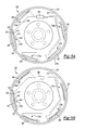
- FIG. 4A illustrates a side view of a braking assembly in accordance with a second preferred embodiment of the present invention in a non-engaged configuration.
- FIG. 4B illustrates the assembly in an engaged configuration in which the brake pad is in frictional contact with the rotatable braking surface.
- FIG. 5A illustrates a side view of a braking assembly in accordance with a third preferred embodiment of the present invention in a non-engaged configuration.
- FIG. 5B illustrates the assembly in an engaged configuration in which the brake pad is in frictional contact with the rotatable braking surface.
- FIG. 6 illustrates a perspective view of a vehicle braking system in accordance with the present invention.
- FIG. 1 illustrates an example of a braking unit 10 in accordance with the present invention.
- the unit 10 preferably includes a base member 12 , a guide member 14 , and a flexible panel 16 extending between the base 12 and guide 14 members.
- One or more flexible rods 18 extend through the flexible panel 16 and into both the base 12 and guide 14 members.
- the base 12 and guide 14 members are preferably secured to a surface, such as a mounting member in a braking assembly, as will be developed more fully below.
- the unit 10 includes a brake pad 56 positioned adjacent the flexible rod 18 .
- the brake pad is positioned adjacent the rod 18 and directly adjacent the flexible panel 16 .
- the base member 12 preferably defines one or more openings 20 that receive and retain one end of the rods 18 .
- the openings 20 preferably retain the rods 18 such that the rod 18 cannot move within the opening 20 .
- the rod 18 may be secured in the opening 20 by any of a variety of means, including an adhesive bond between the rod 18 and block 12 , mechanical attachment, such as crimping, or by way of a fastener, etc. Alternatively, the rod can be secured to a face of the base member 12 .
- the guide member 14 defines openings 22 that provide a passageway 24 from a first face 26 to an opposing second face 28 of the member 14 .
- Each opening 22 receives a second end of a rod 18 and allows the rod 18 to move freely through the passageway 24 .
- a free end of each rod 18 extends past the second edge 28 so that the rod 18 can be deformed by passing a portion of the free end into the passageway 24 , as will be developed more fully below.
- the flexible panel 16 can be omitted if desired.
- the brake pad 56 is preferably secured to the rods 18 .
- the panel 16 preferably comprises a flexible polymeric material that surrounds the portion of the rod 18 that lies between the base 12 and guide 14 members. In this arrangement, deformation of the rod 18 induces stretching or deformation of the flexible panel 16 , which ultimately moves the brake pad 56 .
- the flexible panel 16 comprises an elastomeric material.
- the flexible panel 16 can comprise any flexible material that is able to stretch or deform to a desired degree and return to its original form. The appropriate degree of ability to deform will depend on the application.
- the flexible panel 16 is preferably capable of stretching to 150% of its normal length and still be able to return to its original length and form.
- suitable materials for use in the flexible panel of the present invention include rubber, silicones, silicone rubbers, polyurethanes, and flexible acrylics.
- the flexible panel 16 defines one or more cavities 30 that receive the rods 18 .
- the flexible panel 16 defines one cavity 30 for each rod 18 .
- the flexible panel may define a single, relatively large cavity that receives a plurality or all of the rods 18 .
- the cavities 30 receive the rods 18 in a manner that allows the rods 18 to move within the cavities 30 . That is, the flexible panel 16 is preferably able to slide over the rods 18 , via the cavities 30 , as the rods 18 are pushed or pulled into or out of the cavities 30 .
- the rods 18 are also flexible in nature.
- the rods comprise a composite material that is sufficiently flexible to allow the flexible panel 16 to stretch to its full capacity.
- the rods 18 are able to bend and/or deform in a manner that confers a smooth, continuous shape to the flexible panel 16 , if present.
- Composite materials such as carbon fiber and polymeric materials, provide the desired flexibility when acted upon by an external mechanical force, such as a pushing or pulling action, which will be developed more fully below.
- the rods 18 can comprise any material that possesses the desired flexibility. Examples of suitable alternative materials for use in the rods of the present invention include aluminum, steel and alloyed iron.
- the rods 18 preferably comprise elongate, cylindrical shaped members that can be secured to the base member 12 and can be threaded through the passageway(s) 24 of the guide member 14 and the cavity(ies) 30 of the flexible panel 16 .
- any other suitable shape such as the flexible plates described in U.S. Pat. No. 5,810,291 to Geiger, et al., for a CONTINUOUS MOLDLINE TECHNOLOGY SYSTEM, which is hereby incorporated by reference in its entirety, can be utilized.
- a series of individual rods positioned in parallel or twisted together can be utilized.
- the shape of the passageway(s) 24 and cavity(ies) 30 is preferably complimentary to that of the rods 18 such that the desired flexibility can be achieved.
- the unit 10 also preferably includes an actuator 32 .
- the actuator 32 is a device capable of inducing stretching of the flexible panel 16 and the rods 18 .
- the type of actuator used will depend on the nature of the rods 18 .
- a mechanical actuator can be utilized to push or pull the rods 18 such that the desired stretching is achieved.
- the actuator 32 preferably comprises a motor or other mechanical device.
- the actuator 32 is a motor having a cam 34 that can induce stretching in the rods 18 .
- any other suitable actuator that can induce stretching can be utilized, such as actuators employing hydraulic, pneumatic, or electrical means of inducing movement.
- the actuator 32 can interact with the unit 10 to achieve the desired stretching in a variety of ways.
- the actuator 32 can be attached to the free end of each rod 18 such that the actuator 32 can push or pull the rod 18 into or out of the passageways 24 and cavities 30 .
- the cam 34 can be positioned such that it pushes or pulls the rod 18 , either at the free end or at another location along its length, such that the rod 18 and flexible panel 16 stretch.
- the actuator 32 be able to induce stretching in all rods 18 present in the unit 10 .
- the actuator 32 may induce stretching in only one rod 18 , or a subset of rods 18 .
- the brake pad 56 is positioned adjacent the flexible rod 18 such that deformation of the rod 18 forces the pad 56 to move.
- the pad 56 is connected to the rod 18 . Any suitable connection can be utilized, and bolts or rivets are preferred.
- the pad 56 is positioned directly adjacent the flexible panel 16 . As shown in FIG. 1, it is preferred that the pad 56 substantially span the length of the flexible panel 16 and that the center of the pad 56 be positioned adjacent the center of the flexible panel 16 .
- any conventional brake pad can be utilized as the brake pad 56 in the present invention.
- the brake pad 56 has some flexibility such that it can deform as the flexible panel 16 and/or rod 18 deforms.
- a rigid pad or pad assembly can be utilized.
- the pad should be positioned adjacent the rod 18 and/or flexible panel 16 such that the lack of flexibility does not hinder the ability of the pad to frictionally engage a rotatable braking surface.
- a pad appropriate for the type of rotatable braking surface in the braking assembly is utilized.
- the rotatable brake surface comprises a disc
- any suitable disc brake pad can be utilized.
- the rotatable braking surface comprises a drum
- any suitable drum brake pad can be utilized.
- suitable disc brake pads include those described in U.S. Pat. No. 6,234,284 to Ashman et al. for a FRICTION PAD FOR A DISC BRAKE ASSEMBLY, U.S. Pat. No. 6,193,025 to Nakagawa for a DISK-BRAKE PAD; and U.S. Pat. No. 5,692,585 to Kazuro et al. for a BRAKE PAD WITH A WEAR INDICATOR.
- FIGS. 2, 3 A and 3 B illustrate a first preferred embodiment of a braking assembly 100 in accordance with the present invention.
- Like reference numbers in these Figures refer to similar features and/or components illustrated in FIG. 1 .
- FIG. 3A illustrates the braking assembly 100 of FIG. 2 in a non-engaged configuration
- panel B illustrates the braking assembly 100 in an engaged configuration.
- the braking assembly 100 includes a braking unit 100 connected to a mounting surface 150 .
- the mounting surface 150 preferably comprises a caliper having first 150 a and second 150 b arms.
- the first arm 150 a defines a recess 152 that receives the braking unit 110 .
- the recess 152 provides a back surface that ensures that deformation of the flexible rod 118 and flexible panel 116 occurs in the direction of the clearance between the first 150 a and second 150 b arms of the caliper 150 .
- First 154 and second 156 brake pads are positioned on opposing sides of a rotatable braking surface 158 .
- the rotatable braking surface 158 comprises a disc. Any conventional disc used in disc brake systems can comprise the rotatable braking surface of this embodiment.
- the first brake pad 154 is preferably connected to the caliper 150 such that it is able to frictionally engage the disc 158 when the disc 158 is in contact with the pad 154 .
- the second brake pad 156 is preferably connected to the flexible rod 118 of the braking unit such that deformation of the rod 118 by the actuator 132 induces movement of the pad 156 toward the disc 158 . As shown in FIG. 3B, this movement eliminates the clearance between the brake pad 156 and the disc 158 , resulting in a frictional engagement between these element.
- the braking unit 110 preferably includes a flexible panel 116 and the brake pad 156 is preferably positioned adjacent the flexible panel 116 .
- the brake pad is connected to the flexible panel 116 .
- a connector 136 is connected to the actuator 132 of the braking unit 110 and is adapted to be operably connected to a controller (not illustrated in FIGS. 2 and 3) of a braking system (not illustrated in FIGS. 2 and 3 ), as will be developed more fully below
- FIG. 4 A and FIG. 4B illustrate a braking assembly 200 in accordance with a second preferred embodiment of the present invention. This embodiment is similar to the first preferred embodiment except as detailed below. Accordingly, like reference numbers in FIG. 4 refer to similar features and/or components of the first preferred embodiment.
- the braking assembly 200 comprises a drum brake assembly.
- the braking unit 210 is mounted to a mounting member 268 , such as a hub, such that the attached brake pad 274 is positioned opposite a rotatable drum 270 .
- the brake pad 274 is positioned such that it is able to frictionally engage an inner surface 272 of the drum 270 when the rod 218 and/or flexible panel 216 of the braking unit 210 are deformed by the actuator 232 .
- the braking unit 210 in this embodiment preferably comprises a series of brake pads 274 a - 274 e connected to an elongated rod 218 and flexible panel 216 . Disposed between each pair of brake pads 274 is an additional attachment member 276 a - 276 e .
- These attachment members 276 are preferably identical to guide member 214 except that the passageway in attachment members 276 slideably receives a middle portion of the flexible rod 218 , as opposed to an end portion.
- the attachment members 276 are preferably secured to the mounting member 268 such that the actuator 232 is able to induce deformation of the rod 218 and panel 216 at points between the attachment members 276 by pushing or pulling on the second end of the rod 218 . This allows the actuator 232 to induce frictional contact between a plurality of brake pads 274 and the inner surface 272 of the drum 270 .
- FIG. 4B illustrates the frictional contact achieved by action of the actuator 232 .
- FIG. 5 A and FIG. 5B illustrate a braking assembly 300 in accordance with a third preferred embodiment of the present invention. This embodiment is similar to the second preferred embodiment except as detailed below. Accordingly, like reference numbers in FIG. 5 and FIG. 5B refer to similar features and/or components illustrated in FIG. 4 A and FIG. 4B, respectively.
- the braking assembly 300 comprises a mounting member 368 , a drum 370 , and a plurality of independent braking units 310 a - 310 e.
- Each braking unit 310 includes a brake pad 382 positioned such that it can frictionally engage an inner surface 372 of the drum 370 upon deformation of the rod 318 and flexible panel 316 of the unit 310 .
- a distributor 380 is operably connected to the actuator 332 of each braking unit 310 .
- the type of distributor utilized will depend on the type of actuators employed, and any suitable distributor capable of distributing a single input into multiple outputs can be utilized.
- the distributor 380 comprises a hydraulic device capable of relaying a single input into multiple hydraulic outputs.
- FIG. 6 illustrates a preferred embodiment of a braking system 400 in accordance with the present invention. Again, like reference numbers in FIG. 6 refer to similar features and/or components illustrated in the previous figures.
- the system 400 is adapted for use in a motor vehicle 490 .
- vehicle is not limited to automobiles, and includes any type of device in which it is desirable to selectively slow the motion of a rotating element attached to or forming a part of the device.
- the vehicle 400 includes axles 492 , a primary controller 494 , a primary distributor 496 , and a series of brake lines 498 .
- the vehicle has two front 500 and two rear 502 wheels. Rotatable braking surfaces are associated with each wheel of the vehicle.
- the rotatable braking surface in each of the front wheels 500 comprises a disc 458 and the rotatable braking surface in each of the rear wheels 502 comprises a drum 470
- the braking assembly associated with each of the front wheels 500 preferably comprises a disc-brake assembly in accordance with the present invention.
- the braking assembly associated with each of the rear wheels 502 preferably comprises a drum-brake assembly in accordance with the present invention.
- the primary controller 494 is operably connected to each actuator 432 of each braking assembly.
- the primary controller 494 is adapted to move between two positions: active and inactive positions.
- the primary controller 494 is operably connected to the actuator 432 of each braking assembly such that the actuator 432 induces deformation of the rod 418 and the flexible panel 416 , when the controller 494 is moved to the active position. This causes the brake pad 456 , 474 to frictionally engage the rotatable braking surface 458 , 470 , which slows the motion of the wheel 500 , 502 .
- the primary controller 494 comprises a brake pedal disposed in the passenger compartment of the vehicle 490 such that a user of the vehicle 490 can move the primary controller 494 to the active position by depressing the primary controller 494 with his or her foot.
- a distributor 496 can be operably connected to the primary controller 494 such that a single input (movement of the controller 494 into the active position) is divided into multiple outputs (activation of each actuator 432 to induce deformation of the corresponding rod 418 and flexible panel 416 in several braking assemblies).
- a master cylinder known to those skilled in the art can comprise the distributor 496 .
- the brake lines 498 provide the operable connections between the primary controller 494 and the actuator 432 of each braking unit 410 .
- the type of brake line used will depend on the mode of operation of the primary controller 494 and actuators 432 .
- suitable brake lines for use in the present invention include hydraulic, mechanical, electrical, and electromechanical lines known in the art.
- the brake lines 498 need only be able to induce activation of the actuators 432 to deform the rods 418 in response to movement of the controller 494 into the active position.
Abstract
Description
Claims (10)
Priority Applications (1)
| Application Number | Priority Date | Filing Date | Title |
|---|---|---|---|
| US09/904,408 US6655504B2 (en) | 2000-07-14 | 2001-07-12 | Braking assembly and system |
Applications Claiming Priority (2)
| Application Number | Priority Date | Filing Date | Title |
|---|---|---|---|
| US21849300P | 2000-07-14 | 2000-07-14 | |
| US09/904,408 US6655504B2 (en) | 2000-07-14 | 2001-07-12 | Braking assembly and system |
Publications (2)
| Publication Number | Publication Date |
|---|---|
| US20020043434A1 US20020043434A1 (en) | 2002-04-18 |
| US6655504B2 true US6655504B2 (en) | 2003-12-02 |
Family
ID=26912966
Family Applications (1)
| Application Number | Title | Priority Date | Filing Date |
|---|---|---|---|
| US09/904,408 Expired - Fee Related US6655504B2 (en) | 2000-07-14 | 2001-07-12 | Braking assembly and system |
Country Status (1)
| Country | Link |
|---|---|
| US (1) | US6655504B2 (en) |
Cited By (1)
| Publication number | Priority date | Publication date | Assignee | Title |
|---|---|---|---|---|
| US20210277970A1 (en) * | 2020-03-06 | 2021-09-09 | Howe & Howe Inc. | Failsafe parking brake manual override |
Citations (36)
| Publication number | Priority date | Publication date | Assignee | Title |
|---|---|---|---|---|
| US3425519A (en) * | 1966-06-11 | 1969-02-04 | Teves Kg Alfred | Disk-brake system including plural actuators |
| US3430736A (en) * | 1967-09-25 | 1969-03-04 | Charles E Long | Self adjusting wedge-type disc brake |
| US3583531A (en) * | 1966-11-02 | 1971-06-08 | Safety Vee Brake Inc | Auxiliary brake and braking system |
| US3638766A (en) * | 1970-07-10 | 1972-02-01 | Safety Vee Brake Inc | Manual control for auxiliary brake device |
| US4280753A (en) | 1979-06-13 | 1981-07-28 | Neubauer Frank W | Flexible mirror assembly |
| US4575200A (en) | 1983-07-13 | 1986-03-11 | Humiston Gerald F | Flexible mirror device |
| US5222200A (en) | 1992-01-08 | 1993-06-22 | Lexmark International, Inc. | Automatic printer data stream language determination |
| US5222699A (en) | 1990-04-16 | 1993-06-29 | Ltv Aerospace And Defense Company | Variable control aircraft control surface |
| US5639065A (en) | 1995-09-18 | 1997-06-17 | Lin; Ching-Chung | Vehicle jack |
| US5692585A (en) | 1994-08-08 | 1997-12-02 | Ferodo Abex Sa | Brake pad with a wear indicator |
| US5713557A (en) | 1996-09-24 | 1998-02-03 | Kang; Hsin-Fa | Vehicle jack |
| US5810291A (en) | 1996-03-19 | 1998-09-22 | Geiger; Michael Watson | Continuous moldline technology system |
| US5913494A (en) | 1997-07-25 | 1999-06-22 | Mcdonnell Douglas | Blade seal for an aircraft |
| US5918834A (en) | 1997-02-27 | 1999-07-06 | Mcdonnell Douglas | Retractable sensor system for an aircraft |
| US5927651A (en) | 1997-05-15 | 1999-07-27 | Mcdonnell Douglas | Expandable fuel cell |
| US5931422A (en) | 1997-06-09 | 1999-08-03 | Mcdonnell Douglas | Active reinforced elastomer system |
| US5941480A (en) | 1997-05-08 | 1999-08-24 | Mcdonnell Douglas | Hinge line skin system for an aircraft |
| US5947417A (en) | 1997-07-25 | 1999-09-07 | Mcdonnell Douglas | Fairing for an expandable bay |
| US5947422A (en) | 1997-04-29 | 1999-09-07 | Mcdonnell Douglas | Tail for an aircraft |
| US5958803A (en) | 1996-09-24 | 1999-09-28 | Mcdonnell Douglas | Environmental coating for an elastomer panel |
| US5975463A (en) | 1995-12-21 | 1999-11-02 | Mcdonnell Douglas | Expandable aircraft bay and method |
| US5979828A (en) | 1997-04-30 | 1999-11-09 | Mcdonnell Douglas | Apparatus for eliminating gaps in an aircraft |
| US5988567A (en) | 1997-06-30 | 1999-11-23 | Mcdonnell Douglas | Conformable weapons platform |
| US6027074A (en) | 1997-02-27 | 2000-02-22 | Mcdonnell Douglas | Reinforced elastomer panel |
| US6053477A (en) | 1998-02-18 | 2000-04-25 | Price; Danny C. | Self levering vehicle jack |
| US6068215A (en) | 1995-12-21 | 2000-05-30 | Mcdonnall Douglas | Expandable aircraft cargo bay and method |
| US6076766A (en) | 1998-07-01 | 2000-06-20 | Mcdonnell Douglas Corp. | Folding wing for an aircraft |
| US6089505A (en) | 1997-07-22 | 2000-07-18 | Mcdonnell Douglas Corporation | Mission adaptive inlet |
| US6092764A (en) | 1997-07-21 | 2000-07-25 | Mcdonnell Douglas Corporation | Interface seal for an aircraft |
| US6142501A (en) | 1999-09-09 | 2000-11-07 | Fogo; Neil R. | Recreational vehicle jack remote control |
| US6193025B1 (en) | 1997-11-20 | 2001-02-27 | Sumitomo Electric Industries, Ltd. | Disk-brake pad |
| US6213572B1 (en) | 1997-01-31 | 2001-04-10 | Kelsey-Hayes Company | Electro-hydraulic brake system with electronic pedal simulation |
| US6230949B1 (en) | 1999-11-02 | 2001-05-15 | Daimlerchrysler Corporation | Vehicle jack and tool assembly |
| US6234585B1 (en) | 1997-02-03 | 2001-05-22 | Alan Leslie Harris | Electronic braking system for vehicles |
| US6234284B1 (en) | 1997-01-18 | 2001-05-22 | Lucas Industries Limited | Friction pad for a disc brake assembly |
| US6386338B1 (en) * | 2000-12-01 | 2002-05-14 | Dura Global Technologies, Inc. | Electric parking brake manual override |
-
2001
- 2001-07-12 US US09/904,408 patent/US6655504B2/en not_active Expired - Fee Related
Patent Citations (37)
| Publication number | Priority date | Publication date | Assignee | Title |
|---|---|---|---|---|
| US3425519A (en) * | 1966-06-11 | 1969-02-04 | Teves Kg Alfred | Disk-brake system including plural actuators |
| US3583531A (en) * | 1966-11-02 | 1971-06-08 | Safety Vee Brake Inc | Auxiliary brake and braking system |
| US3430736A (en) * | 1967-09-25 | 1969-03-04 | Charles E Long | Self adjusting wedge-type disc brake |
| US3638766A (en) * | 1970-07-10 | 1972-02-01 | Safety Vee Brake Inc | Manual control for auxiliary brake device |
| US4280753A (en) | 1979-06-13 | 1981-07-28 | Neubauer Frank W | Flexible mirror assembly |
| US4575200A (en) | 1983-07-13 | 1986-03-11 | Humiston Gerald F | Flexible mirror device |
| US5222699A (en) | 1990-04-16 | 1993-06-29 | Ltv Aerospace And Defense Company | Variable control aircraft control surface |
| US5222200A (en) | 1992-01-08 | 1993-06-22 | Lexmark International, Inc. | Automatic printer data stream language determination |
| US5692585A (en) | 1994-08-08 | 1997-12-02 | Ferodo Abex Sa | Brake pad with a wear indicator |
| US5639065A (en) | 1995-09-18 | 1997-06-17 | Lin; Ching-Chung | Vehicle jack |
| US5975463A (en) | 1995-12-21 | 1999-11-02 | Mcdonnell Douglas | Expandable aircraft bay and method |
| US6068215A (en) | 1995-12-21 | 2000-05-30 | Mcdonnall Douglas | Expandable aircraft cargo bay and method |
| US5810291A (en) | 1996-03-19 | 1998-09-22 | Geiger; Michael Watson | Continuous moldline technology system |
| US5713557A (en) | 1996-09-24 | 1998-02-03 | Kang; Hsin-Fa | Vehicle jack |
| US6048581A (en) | 1996-09-24 | 2000-04-11 | Mcdonnell Douglas Corporation | Elastic ground plane and method |
| US5958803A (en) | 1996-09-24 | 1999-09-28 | Mcdonnell Douglas | Environmental coating for an elastomer panel |
| US6234284B1 (en) | 1997-01-18 | 2001-05-22 | Lucas Industries Limited | Friction pad for a disc brake assembly |
| US6213572B1 (en) | 1997-01-31 | 2001-04-10 | Kelsey-Hayes Company | Electro-hydraulic brake system with electronic pedal simulation |
| US6234585B1 (en) | 1997-02-03 | 2001-05-22 | Alan Leslie Harris | Electronic braking system for vehicles |
| US5918834A (en) | 1997-02-27 | 1999-07-06 | Mcdonnell Douglas | Retractable sensor system for an aircraft |
| US6027074A (en) | 1997-02-27 | 2000-02-22 | Mcdonnell Douglas | Reinforced elastomer panel |
| US5947422A (en) | 1997-04-29 | 1999-09-07 | Mcdonnell Douglas | Tail for an aircraft |
| US5979828A (en) | 1997-04-30 | 1999-11-09 | Mcdonnell Douglas | Apparatus for eliminating gaps in an aircraft |
| US5941480A (en) | 1997-05-08 | 1999-08-24 | Mcdonnell Douglas | Hinge line skin system for an aircraft |
| US5927651A (en) | 1997-05-15 | 1999-07-27 | Mcdonnell Douglas | Expandable fuel cell |
| US5931422A (en) | 1997-06-09 | 1999-08-03 | Mcdonnell Douglas | Active reinforced elastomer system |
| US5988567A (en) | 1997-06-30 | 1999-11-23 | Mcdonnell Douglas | Conformable weapons platform |
| US6092764A (en) | 1997-07-21 | 2000-07-25 | Mcdonnell Douglas Corporation | Interface seal for an aircraft |
| US6089505A (en) | 1997-07-22 | 2000-07-18 | Mcdonnell Douglas Corporation | Mission adaptive inlet |
| US5947417A (en) | 1997-07-25 | 1999-09-07 | Mcdonnell Douglas | Fairing for an expandable bay |
| US5913494A (en) | 1997-07-25 | 1999-06-22 | Mcdonnell Douglas | Blade seal for an aircraft |
| US6193025B1 (en) | 1997-11-20 | 2001-02-27 | Sumitomo Electric Industries, Ltd. | Disk-brake pad |
| US6053477A (en) | 1998-02-18 | 2000-04-25 | Price; Danny C. | Self levering vehicle jack |
| US6076766A (en) | 1998-07-01 | 2000-06-20 | Mcdonnell Douglas Corp. | Folding wing for an aircraft |
| US6142501A (en) | 1999-09-09 | 2000-11-07 | Fogo; Neil R. | Recreational vehicle jack remote control |
| US6230949B1 (en) | 1999-11-02 | 2001-05-15 | Daimlerchrysler Corporation | Vehicle jack and tool assembly |
| US6386338B1 (en) * | 2000-12-01 | 2002-05-14 | Dura Global Technologies, Inc. | Electric parking brake manual override |
Cited By (2)
| Publication number | Priority date | Publication date | Assignee | Title |
|---|---|---|---|---|
| US20210277970A1 (en) * | 2020-03-06 | 2021-09-09 | Howe & Howe Inc. | Failsafe parking brake manual override |
| US11840167B2 (en) * | 2020-03-06 | 2023-12-12 | Howe & Howe Inc. | Failsafe parking brake manual override |
Also Published As
| Publication number | Publication date |
|---|---|
| US20020043434A1 (en) | 2002-04-18 |
Similar Documents
| Publication | Publication Date | Title |
|---|---|---|
| KR102636937B1 (en) | Brake caliper guide pin low pressure isolation damper | |
| KR101922476B1 (en) | Electric caliper brake with parking function | |
| US6655504B2 (en) | Braking assembly and system | |
| JP4109741B2 (en) | Electric brake | |
| US3532196A (en) | Caliper disc brake with mechanical actuator | |
| US3439780A (en) | Disk brake and actuator therefor | |
| US3456765A (en) | Fixed-yoke disk brake | |
| US1972829A (en) | Hydraulic brake | |
| US8919502B2 (en) | Cord assembly for replacement of outer beam and carrier including the same | |
| JP4240055B2 (en) | Electric brake | |
| KR100771041B1 (en) | The Disk Brake | |
| KR20080010851A (en) | A brake pad for vehicle's disc brakes | |
| KR0163226B1 (en) | Drum brake | |
| KR200281960Y1 (en) | Disc brake | |
| KR100218164B1 (en) | Disk brake having inner and outer piston | |
| KR20040071893A (en) | Disc brake | |
| KR100534255B1 (en) | Brake-shoe Structure of Drum Brake | |
| KR0118021B1 (en) | The variable oil-pressure structure subjected to the weight loaded in a vehicle | |
| KR0135328Y1 (en) | Wheel brake device by ball | |
| KR100349539B1 (en) | Disk brake | |
| KR200247108Y1 (en) | Drum brake for vehicle | |
| KR200267843Y1 (en) | Drum brake system | |
| KR19980074843A (en) | Hydraulic piston structure of disc brake with built-in parking brake | |
| KR19980038831U (en) | Friction pads on disc brakes | |
| KR0137767Y1 (en) | Support structure of shoe of parking brake for a vehicle |
Legal Events
| Date | Code | Title | Description |
|---|---|---|---|
| AS | Assignment |
Owner name: VISTEON GLOBAL TECHNOLOGIES, INC., MICHIGAN Free format text: ASSIGNMENT OF ASSIGNORS INTEREST;ASSIGNORS:GLOVATSKY, ANDREW ZACHARY;BELKE, ROBERT EDWARD;BAKER, JAY DEAVIS;AND OTHERS;REEL/FRAME:012161/0638;SIGNING DATES FROM 20010711 TO 20010725 |
|
| FPAY | Fee payment |
Year of fee payment: 4 |
|
| AS | Assignment |
Owner name: JPMORGAN CHASE BANK, N.A., AS ADMINISTRATIVE AGENT Free format text: SECURITY AGREEMENT;ASSIGNOR:VISTEON GLOBAL TECHNOLOGIES, INC.;REEL/FRAME:020497/0733 Effective date: 20060613 |
|
| AS | Assignment |
Owner name: JPMORGAN CHASE BANK, TEXAS Free format text: SECURITY INTEREST;ASSIGNOR:VISTEON GLOBAL TECHNOLOGIES, INC.;REEL/FRAME:022368/0001 Effective date: 20060814 Owner name: JPMORGAN CHASE BANK,TEXAS Free format text: SECURITY INTEREST;ASSIGNOR:VISTEON GLOBAL TECHNOLOGIES, INC.;REEL/FRAME:022368/0001 Effective date: 20060814 |
|
| AS | Assignment |
Owner name: WILMINGTON TRUST FSB, AS ADMINISTRATIVE AGENT, MIN Free format text: ASSIGNMENT OF SECURITY INTEREST IN PATENTS;ASSIGNOR:JPMORGAN CHASE BANK, N.A., AS ADMINISTRATIVE AGENT;REEL/FRAME:022575/0186 Effective date: 20090415 Owner name: WILMINGTON TRUST FSB, AS ADMINISTRATIVE AGENT,MINN Free format text: ASSIGNMENT OF SECURITY INTEREST IN PATENTS;ASSIGNOR:JPMORGAN CHASE BANK, N.A., AS ADMINISTRATIVE AGENT;REEL/FRAME:022575/0186 Effective date: 20090415 |
|
| AS | Assignment |
Owner name: THE BANK OF NEW YORK MELLON, AS ADMINISTRATIVE AGE Free format text: ASSIGNMENT OF PATENT SECURITY INTEREST;ASSIGNOR:JPMORGAN CHASE BANK, N.A., A NATIONAL BANKING ASSOCIATION;REEL/FRAME:022974/0057 Effective date: 20090715 |
|
| AS | Assignment |
Owner name: VISTEON GLOBAL TECHNOLOGIES, INC., MICHIGAN Free format text: RELEASE BY SECURED PARTY AGAINST SECURITY INTEREST IN PATENTS RECORDED AT REEL 022974 FRAME 0057;ASSIGNOR:THE BANK OF NEW YORK MELLON;REEL/FRAME:025095/0711 Effective date: 20101001 |
|
| AS | Assignment |
Owner name: VISTEON GLOBAL TECHNOLOGIES, INC., MICHIGAN Free format text: RELEASE BY SECURED PARTY AGAINST SECURITY INTEREST IN PATENTS RECORDED AT REEL 022575 FRAME 0186;ASSIGNOR:WILMINGTON TRUST FSB, AS ADMINISTRATIVE AGENT;REEL/FRAME:025105/0201 Effective date: 20101001 |
|
| AS | Assignment |
Owner name: MORGAN STANLEY SENIOR FUNDING, INC., AS AGENT, NEW Free format text: SECURITY AGREEMENT (REVOLVER);ASSIGNORS:VISTEON CORPORATION;VC AVIATION SERVICES, LLC;VISTEON ELECTRONICS CORPORATION;AND OTHERS;REEL/FRAME:025238/0298 Effective date: 20101001 Owner name: MORGAN STANLEY SENIOR FUNDING, INC., AS AGENT, NEW Free format text: SECURITY AGREEMENT;ASSIGNORS:VISTEON CORPORATION;VC AVIATION SERVICES, LLC;VISTEON ELECTRONICS CORPORATION;AND OTHERS;REEL/FRAME:025241/0317 Effective date: 20101007 |
|
| AS | Assignment |
Owner name: VC AVIATION SERVICES, LLC, MICHIGAN Free format text: RELEASE BY SECURED PARTY AGAINST SECURITY INTEREST IN PATENTS ON REEL 025241 FRAME 0317;ASSIGNOR:MORGAN STANLEY SENIOR FUNDING, INC.;REEL/FRAME:026178/0412 Effective date: 20110406 Owner name: VISTEON ELECTRONICS CORPORATION, MICHIGAN Free format text: RELEASE BY SECURED PARTY AGAINST SECURITY INTEREST IN PATENTS ON REEL 025241 FRAME 0317;ASSIGNOR:MORGAN STANLEY SENIOR FUNDING, INC.;REEL/FRAME:026178/0412 Effective date: 20110406 Owner name: VISTEON GLOBAL TECHNOLOGIES, INC., MICHIGAN Free format text: RELEASE BY SECURED PARTY AGAINST SECURITY INTEREST IN PATENTS ON REEL 025241 FRAME 0317;ASSIGNOR:MORGAN STANLEY SENIOR FUNDING, INC.;REEL/FRAME:026178/0412 Effective date: 20110406 Owner name: VISTEON INTERNATIONAL BUSINESS DEVELOPMENT, INC., Free format text: RELEASE BY SECURED PARTY AGAINST SECURITY INTEREST IN PATENTS ON REEL 025241 FRAME 0317;ASSIGNOR:MORGAN STANLEY SENIOR FUNDING, INC.;REEL/FRAME:026178/0412 Effective date: 20110406 Owner name: VISTEON GLOBAL TREASURY, INC., MICHIGAN Free format text: RELEASE BY SECURED PARTY AGAINST SECURITY INTEREST IN PATENTS ON REEL 025241 FRAME 0317;ASSIGNOR:MORGAN STANLEY SENIOR FUNDING, INC.;REEL/FRAME:026178/0412 Effective date: 20110406 Owner name: VISTEON INTERNATIONAL HOLDINGS, INC., MICHIGAN Free format text: RELEASE BY SECURED PARTY AGAINST SECURITY INTEREST IN PATENTS ON REEL 025241 FRAME 0317;ASSIGNOR:MORGAN STANLEY SENIOR FUNDING, INC.;REEL/FRAME:026178/0412 Effective date: 20110406 Owner name: VISTEON CORPORATION, MICHIGAN Free format text: RELEASE BY SECURED PARTY AGAINST SECURITY INTEREST IN PATENTS ON REEL 025241 FRAME 0317;ASSIGNOR:MORGAN STANLEY SENIOR FUNDING, INC.;REEL/FRAME:026178/0412 Effective date: 20110406 Owner name: VISTEON SYSTEMS, LLC, MICHIGAN Free format text: RELEASE BY SECURED PARTY AGAINST SECURITY INTEREST IN PATENTS ON REEL 025241 FRAME 0317;ASSIGNOR:MORGAN STANLEY SENIOR FUNDING, INC.;REEL/FRAME:026178/0412 Effective date: 20110406 Owner name: VISTEON EUROPEAN HOLDING, INC., MICHIGAN Free format text: RELEASE BY SECURED PARTY AGAINST SECURITY INTEREST IN PATENTS ON REEL 025241 FRAME 0317;ASSIGNOR:MORGAN STANLEY SENIOR FUNDING, INC.;REEL/FRAME:026178/0412 Effective date: 20110406 |
|
| REMI | Maintenance fee reminder mailed | ||
| LAPS | Lapse for failure to pay maintenance fees | ||
| STCH | Information on status: patent discontinuation |
Free format text: PATENT EXPIRED DUE TO NONPAYMENT OF MAINTENANCE FEES UNDER 37 CFR 1.362 |
|
| FP | Lapsed due to failure to pay maintenance fee |
Effective date: 20111202 |
|
| AS | Assignment |
Owner name: VISTEON INTERNATIONAL BUSINESS DEVELOPMENT, INC., Free format text: RELEASE OF SECURITY INTEREST IN INTELLECTUAL PROPERTY;ASSIGNOR:MORGAN STANLEY SENIOR FUNDING, INC.;REEL/FRAME:033107/0717 Effective date: 20140409 Owner name: VC AVIATION SERVICES, LLC, MICHIGAN Free format text: RELEASE OF SECURITY INTEREST IN INTELLECTUAL PROPERTY;ASSIGNOR:MORGAN STANLEY SENIOR FUNDING, INC.;REEL/FRAME:033107/0717 Effective date: 20140409 Owner name: VISTEON SYSTEMS, LLC, MICHIGAN Free format text: RELEASE OF SECURITY INTEREST IN INTELLECTUAL PROPERTY;ASSIGNOR:MORGAN STANLEY SENIOR FUNDING, INC.;REEL/FRAME:033107/0717 Effective date: 20140409 Owner name: VISTEON GLOBAL TECHNOLOGIES, INC., MICHIGAN Free format text: RELEASE OF SECURITY INTEREST IN INTELLECTUAL PROPERTY;ASSIGNOR:MORGAN STANLEY SENIOR FUNDING, INC.;REEL/FRAME:033107/0717 Effective date: 20140409 Owner name: VISTEON GLOBAL TREASURY, INC., MICHIGAN Free format text: RELEASE OF SECURITY INTEREST IN INTELLECTUAL PROPERTY;ASSIGNOR:MORGAN STANLEY SENIOR FUNDING, INC.;REEL/FRAME:033107/0717 Effective date: 20140409 Owner name: VISTEON CORPORATION, MICHIGAN Free format text: RELEASE OF SECURITY INTEREST IN INTELLECTUAL PROPERTY;ASSIGNOR:MORGAN STANLEY SENIOR FUNDING, INC.;REEL/FRAME:033107/0717 Effective date: 20140409 Owner name: VISTEON INTERNATIONAL HOLDINGS, INC., MICHIGAN Free format text: RELEASE OF SECURITY INTEREST IN INTELLECTUAL PROPERTY;ASSIGNOR:MORGAN STANLEY SENIOR FUNDING, INC.;REEL/FRAME:033107/0717 Effective date: 20140409 Owner name: VISTEON ELECTRONICS CORPORATION, MICHIGAN Free format text: RELEASE OF SECURITY INTEREST IN INTELLECTUAL PROPERTY;ASSIGNOR:MORGAN STANLEY SENIOR FUNDING, INC.;REEL/FRAME:033107/0717 Effective date: 20140409 Owner name: VISTEON EUROPEAN HOLDINGS, INC., MICHIGAN Free format text: RELEASE OF SECURITY INTEREST IN INTELLECTUAL PROPERTY;ASSIGNOR:MORGAN STANLEY SENIOR FUNDING, INC.;REEL/FRAME:033107/0717 Effective date: 20140409 |