US6655180B2 - Locker lock with adjustable bolt - Google Patents
Locker lock with adjustable bolt Download PDFInfo
- Publication number
- US6655180B2 US6655180B2 US09/919,723 US91972301A US6655180B2 US 6655180 B2 US6655180 B2 US 6655180B2 US 91972301 A US91972301 A US 91972301A US 6655180 B2 US6655180 B2 US 6655180B2
- Authority
- US
- United States
- Prior art keywords
- bolt
- lock
- latch
- door
- housing
- Prior art date
- Legal status (The legal status is an assumption and is not a legal conclusion. Google has not performed a legal analysis and makes no representation as to the accuracy of the status listed.)
- Expired - Lifetime
Links
- 230000007246 mechanism Effects 0.000 claims description 30
- 230000037431 insertion Effects 0.000 claims 1
- 238000003780 insertion Methods 0.000 claims 1
- 230000033001 locomotion Effects 0.000 description 6
- 239000002184 metal Substances 0.000 description 5
- 239000002023 wood Substances 0.000 description 5
- 238000002360 preparation method Methods 0.000 description 4
- 230000009471 action Effects 0.000 description 3
- 230000003287 optical effect Effects 0.000 description 3
- 239000004606 Fillers/Extenders Substances 0.000 description 2
- 238000010276 construction Methods 0.000 description 2
- 230000000712 assembly Effects 0.000 description 1
- 238000000429 assembly Methods 0.000 description 1
- 238000013474 audit trail Methods 0.000 description 1
- 238000010586 diagram Methods 0.000 description 1
- 238000005516 engineering process Methods 0.000 description 1
- 230000006870 function Effects 0.000 description 1
- 230000036541 health Effects 0.000 description 1
- 230000010354 integration Effects 0.000 description 1
- 230000007774 longterm Effects 0.000 description 1
- 230000006386 memory function Effects 0.000 description 1
- 230000004048 modification Effects 0.000 description 1
- 238000012986 modification Methods 0.000 description 1
Images


Classifications
-
- G—PHYSICS
- G07—CHECKING-DEVICES
- G07C—TIME OR ATTENDANCE REGISTERS; REGISTERING OR INDICATING THE WORKING OF MACHINES; GENERATING RANDOM NUMBERS; VOTING OR LOTTERY APPARATUS; ARRANGEMENTS, SYSTEMS OR APPARATUS FOR CHECKING NOT PROVIDED FOR ELSEWHERE
- G07C9/00—Individual registration on entry or exit
- G07C9/00174—Electronically operated locks; Circuits therefor; Nonmechanical keys therefor, e.g. passive or active electrical keys or other data carriers without mechanical keys
- G07C9/00658—Electronically operated locks; Circuits therefor; Nonmechanical keys therefor, e.g. passive or active electrical keys or other data carriers without mechanical keys operated by passive electrical keys
- G07C9/00674—Electronically operated locks; Circuits therefor; Nonmechanical keys therefor, e.g. passive or active electrical keys or other data carriers without mechanical keys operated by passive electrical keys with switch-buttons
-
- E—FIXED CONSTRUCTIONS
- E05—LOCKS; KEYS; WINDOW OR DOOR FITTINGS; SAFES
- E05B—LOCKS; ACCESSORIES THEREFOR; HANDCUFFS
- E05B63/00—Locks or fastenings with special structural characteristics
- E05B63/06—Locks or fastenings with special structural characteristics with lengthwise-adjustable bolts ; with adjustable backset, i.e. distance from door edge
-
- E—FIXED CONSTRUCTIONS
- E05—LOCKS; KEYS; WINDOW OR DOOR FITTINGS; SAFES
- E05B—LOCKS; ACCESSORIES THEREFOR; HANDCUFFS
- E05B47/00—Operating or controlling locks or other fastening devices by electric or magnetic means
- E05B47/0001—Operating or controlling locks or other fastening devices by electric or magnetic means with electric actuators; Constructional features thereof
- E05B2047/0014—Constructional features of actuators or power transmissions therefor
- E05B2047/0015—Output elements of actuators
-
- E—FIXED CONSTRUCTIONS
- E05—LOCKS; KEYS; WINDOW OR DOOR FITTINGS; SAFES
- E05B—LOCKS; ACCESSORIES THEREFOR; HANDCUFFS
- E05B47/00—Operating or controlling locks or other fastening devices by electric or magnetic means
- E05B47/0001—Operating or controlling locks or other fastening devices by electric or magnetic means with electric actuators; Constructional features thereof
- E05B2047/0014—Constructional features of actuators or power transmissions therefor
- E05B2047/0018—Details of actuator transmissions
- E05B2047/0023—Nuts or nut-like elements moving along a driven threaded axle
-
- E—FIXED CONSTRUCTIONS
- E05—LOCKS; KEYS; WINDOW OR DOOR FITTINGS; SAFES
- E05B—LOCKS; ACCESSORIES THEREFOR; HANDCUFFS
- E05B47/00—Operating or controlling locks or other fastening devices by electric or magnetic means
- E05B47/0001—Operating or controlling locks or other fastening devices by electric or magnetic means with electric actuators; Constructional features thereof
- E05B2047/0014—Constructional features of actuators or power transmissions therefor
- E05B2047/0018—Details of actuator transmissions
- E05B2047/0024—Cams
-
- E—FIXED CONSTRUCTIONS
- E05—LOCKS; KEYS; WINDOW OR DOOR FITTINGS; SAFES
- E05B—LOCKS; ACCESSORIES THEREFOR; HANDCUFFS
- E05B47/00—Operating or controlling locks or other fastening devices by electric or magnetic means
- E05B2047/0048—Circuits, feeding, monitoring
- E05B2047/0057—Feeding
- E05B2047/0058—Feeding by batteries
-
- E—FIXED CONSTRUCTIONS
- E05—LOCKS; KEYS; WINDOW OR DOOR FITTINGS; SAFES
- E05B—LOCKS; ACCESSORIES THEREFOR; HANDCUFFS
- E05B47/00—Operating or controlling locks or other fastening devices by electric or magnetic means
- E05B2047/0048—Circuits, feeding, monitoring
- E05B2047/0067—Monitoring
- E05B2047/0069—Monitoring bolt position
-
- E—FIXED CONSTRUCTIONS
- E05—LOCKS; KEYS; WINDOW OR DOOR FITTINGS; SAFES
- E05B—LOCKS; ACCESSORIES THEREFOR; HANDCUFFS
- E05B47/00—Operating or controlling locks or other fastening devices by electric or magnetic means
- E05B47/0001—Operating or controlling locks or other fastening devices by electric or magnetic means with electric actuators; Constructional features thereof
- E05B47/0012—Operating or controlling locks or other fastening devices by electric or magnetic means with electric actuators; Constructional features thereof with rotary electromotors
-
- E—FIXED CONSTRUCTIONS
- E05—LOCKS; KEYS; WINDOW OR DOOR FITTINGS; SAFES
- E05B—LOCKS; ACCESSORIES THEREFOR; HANDCUFFS
- E05B63/00—Locks or fastenings with special structural characteristics
- E05B63/0056—Locks with adjustable or exchangeable lock parts
-
- E—FIXED CONSTRUCTIONS
- E05—LOCKS; KEYS; WINDOW OR DOOR FITTINGS; SAFES
- E05B—LOCKS; ACCESSORIES THEREFOR; HANDCUFFS
- E05B65/00—Locks or fastenings for special use
- E05B65/02—Locks or fastenings for special use for thin, hollow, or thin-metal wings
- E05B65/025—Locks or fastenings for special use for thin, hollow, or thin-metal wings for lockers
-
- G—PHYSICS
- G07—CHECKING-DEVICES
- G07C—TIME OR ATTENDANCE REGISTERS; REGISTERING OR INDICATING THE WORKING OF MACHINES; GENERATING RANDOM NUMBERS; VOTING OR LOTTERY APPARATUS; ARRANGEMENTS, SYSTEMS OR APPARATUS FOR CHECKING NOT PROVIDED FOR ELSEWHERE
- G07C9/00—Individual registration on entry or exit
- G07C9/00174—Electronically operated locks; Circuits therefor; Nonmechanical keys therefor, e.g. passive or active electrical keys or other data carriers without mechanical keys
- G07C2009/00634—Power supply for the lock
- G07C2009/00642—Power supply for the lock by battery
-
- Y—GENERAL TAGGING OF NEW TECHNOLOGICAL DEVELOPMENTS; GENERAL TAGGING OF CROSS-SECTIONAL TECHNOLOGIES SPANNING OVER SEVERAL SECTIONS OF THE IPC; TECHNICAL SUBJECTS COVERED BY FORMER USPC CROSS-REFERENCE ART COLLECTIONS [XRACs] AND DIGESTS
- Y10—TECHNICAL SUBJECTS COVERED BY FORMER USPC
- Y10T—TECHNICAL SUBJECTS COVERED BY FORMER US CLASSIFICATION
- Y10T70/00—Locks
- Y10T70/70—Operating mechanism
- Y10T70/7051—Using a powered device [e.g., motor]
- Y10T70/7062—Electrical type [e.g., solenoid]
- Y10T70/7068—Actuated after correct combination recognized [e.g., numerical, alphabetical, or magnet[s] pattern]
-
- Y—GENERAL TAGGING OF NEW TECHNOLOGICAL DEVELOPMENTS; GENERAL TAGGING OF CROSS-SECTIONAL TECHNOLOGIES SPANNING OVER SEVERAL SECTIONS OF THE IPC; TECHNICAL SUBJECTS COVERED BY FORMER USPC CROSS-REFERENCE ART COLLECTIONS [XRACs] AND DIGESTS
- Y10—TECHNICAL SUBJECTS COVERED BY FORMER USPC
- Y10T—TECHNICAL SUBJECTS COVERED BY FORMER US CLASSIFICATION
- Y10T70/00—Locks
- Y10T70/80—Parts, attachments, accessories and adjuncts
- Y10T70/8027—Condition indicators
-
- Y—GENERAL TAGGING OF NEW TECHNOLOGICAL DEVELOPMENTS; GENERAL TAGGING OF CROSS-SECTIONAL TECHNOLOGIES SPANNING OVER SEVERAL SECTIONS OF THE IPC; TECHNICAL SUBJECTS COVERED BY FORMER USPC CROSS-REFERENCE ART COLLECTIONS [XRACs] AND DIGESTS
- Y10—TECHNICAL SUBJECTS COVERED BY FORMER USPC
- Y10T—TECHNICAL SUBJECTS COVERED BY FORMER US CLASSIFICATION
- Y10T70/00—Locks
- Y10T70/80—Parts, attachments, accessories and adjuncts
- Y10T70/8838—Adjustment provisions
Definitions
- This invention is concerned with security of lockers, safes, desks, cabinets or other such storage devices assigned for temporary or long-term use.
- the invention relates to a lock operated by an electronic identification means for such storage situations.
- Electric locks are well known.
- hotel safes for temporary use by guests have included digital locks with keypad and other electronic identification means to provide access to the hotel guest.
- the guest is able to select his/her own combination for the lock and in others the guest is issued a pre-selected number or some electronic identification means used as the “key” for the lock device.
- no single locking device has been able to address the problem of adaptability to various door types and door preparations.
- Metal lockers manufactured in the United States typically are equipped with a vertical locking bar, which locks the door unit to the frame in two or three points. The lock mechanism blocks this vertical locking bar.
- the locker employs a single point latch mechanism. In both cases the majority of lockers utilize a three-hole door preparation and a locking position that is standard. However, the bolt or latch length required for the three point locking bar is different from that required for a single point latch, making it difficult to use a single locking device which would fit for both applications.
- a locking mechanism shown by the instant invention provides a locking mechanism to address numerous door types and preparations as well as numerous functionalities.
- An important object of the invention is to provide an electro mechanical lock that fits to various standard door preparations without any modification, providing instant retrofit capability to various types of doors, and including programmable bolt extension length that is adjustable to the particular locking application. Another object of the invention is to provide a locking mechanism that is easy to use by people with disabilities. Yet another objection of the invention is to allow numerous functionalities to cover different usages. A further object is to provide improved bolt drive systems for the lock units described in U.S. Pat. Nos. 5,886,644 and 5,894,277, and the disclosure of those patents are incorporated herein by reference.
- FIG. 1 is an exploded view in perspective, indicating the assembly of two sub units or housings of the electronic lock through a metal locker door.
- FIG. 2 is a view similar to FIG. 1, but indicating the inner and outer housings as being assembled through a wood door, and showing a connection extender.
- FIG. 3 is a perspective view showing a metal locker door front with a lock recess fitted with a keypad unit in an embodiment of the electronic lock.
- FIG. 4 is a perspective view showing a front unit of an electronic lock, with an button contact rather than a keypad.
- FIG. 5 is an elevation view showing the interior of an electronic locking device with a bolt unit of the invention.
- FIG. 6 is a detailed view showing a bolt carrier and linkage and bolt which form a part of the assembly shown in FIG. 5 .
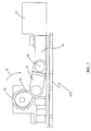
- FIG. 7 is a schematic side view showing a portion of the assembly of FIG. 5 and indicating the action of a motor driving a bolt linkage and bolt of the lock.
- FIG. 8 is a schematic view indicating different settable positions of an adjustable throw bolt of the assembly shown in FIGS. 5-7.
- FIG. 9 is a diagram to explain a preferred embodiment of position-sensored logic associated with the device of FIGS. 5-8.
- FIG. 10 is an elevation view showing the interior of an electronic locking device of the invention with a bolt unit set to extend to one protrusion length, e.g., 5 ⁇ 8′′.
- FIG. 10A is an elevation view showing the interior of an electronic locking device of the invention with a bolt unit set to extend to another protrusion, e.g., 3 ⁇ 8′′.
- FIG. 10B is an elevation view showing the interior of an electronic locking device of the invention with a bolt unit set to extend to another protrusion, e.g, 1 ⁇ 4′′.
- FIG. 10C is an elevation view showing the interior of an electronic locking device of the invention with the bolt in the retracted position.
- FIG. 11 is an elevation view showing the interior of an electronic locking device with a spring latch unit of the invention.
- FIG. 11A is a schematic side view showing a portion of the assembly of FIG. 11 and indicating the action of a motor driving the spring loaded latch unit with the movement of a cam unit.
- FIG. 12 is an elevation view showing the interior of an electronic locking device of the invention with a bolt unit employing a screw drive mechanism and shown with the longest protrusion, e.g., 5 ⁇ 8′′.
- FIG. 12A is an elevation view showing the interior of an electronic locking device of the invention with a bolt unit employing a screw drive mechanism and shown with 3 ⁇ 8′′ protrusion, for example.
- FIG. 12B is an elevation view showing the interior of an electronic locking device of the invention with a bolt unit employing a screw drive mechanism and shown with 1 ⁇ 4′′ protrusion, for example.
- FIG. 12C is an elevation view showing the interior of an electronic locking device of the invention with a bolt unit employing a screw drive mechanism and shown in retracted position.
- FIG. 13 is an isometric view of the screw drive systems bolt carrier unit used with a bolt.
- FIG. 13A is an isometric view of the screw drive systems bolt carrier unit used with a spring latch.
- FIG. 14 is an elevation view showing the interior of an electronic locking device utilizing the screw drive mechanism with a spring latch unit of the invention.
- FIG. 1 shows a portion of a locker door or cabinet door 10 which, in this case, has a recessed lock mounting 12 , recessed inwardly in the metal door.
- the illustrated door has a standard three-hole door prep identified generally as 14 , with two opposed mounting holes 16 at top and bottom and a larger center hole 18 .
- the hole 18 conventionally was intended to receive the dial shaft of a built-in combination lock or a key hole of the key operated built-in combination lock.
- the lock device of this invention includes an outer housing 20 and an inner housing 22 , shown separated and on either side of the door 10 , as they are assembled by connecting them with electrical pin 24 and socket 26 connectors through the recess 14 of the door, in a sandwiched construction. All this is as described in U.S. Pat. No. 5,894,277, assigned to the assignee of this invention and incorporated herein by reference. As explained in that patent, fastening bores 28 at the back side of the outer housing 20 and fastening holes 30 in the inner housing 22 are lined up with the upper and lower locker door holes 16 to receive fasteners to secure the assembly together.
- the bores 28 on the outer housing are tapped, and the inner housing holes 30 are through-holes so that a pair of machine screws can secure the two units together and to the door recess 12 .
- the front unit 20 may be fitted with threaded posts at the location 28 which will go through the holes 16 and 30 and fastened with nuts behind new unit 22 sandwiching the mounting plate 12 .
- FIG. 2 indicates that the same inner and outer housings 22 and 20 can be used on a wood door 31 , which has a much larger thickness to be penetrated with the sandwiched assembly. This can be accomplished with a connection extender 32 as shown.
- FIG. 3 shows an example of a locker front 34 , which could be the front of the locker door 10 shown in FIG. 1, with an electronic door access device 36 which can include the front housing 20 shown in FIG. 1 .
- the front housing 20 has a keypad 38 , but, as shown in FIG. 4, the front housing 20 a can have an ibutton contact 40 , which provides for electronic access by contact with the user's hand-held ibutton as explained in U.S. Pat. No. 5,886,644 assigned to the assignee of this invention and incorporated by reference herein.
- the access device or electronic access means can also include other types of readers such as proximity devices, transponders, radio frequency or infrared readers which can communicate the user's I.D.
- the item 40 in FIG. 4 can represent a reader or receiving device for other identification technologies mentioned above such as proximity cards or infrared devices.
- Other features on the face of the ibutton-receiving outer housing 20 a are explained in the '644 patent.
- a key slot 41 is included in the electronic access device 36 in one preferred embodiment. This is for access by a manager.
- the manager possesses a small key with a small blade which actually comprises a circuit board with traces, connected to an ibutton. This key is used for manager functions, such as opening the locker without the need for entry of a manager code on the keypad.
- the advantages are that the user does not see the manager code, which could be misused; a unique manager key code can be assigned and deleted when needed (such as if a key is lost); and each manager holding a key can be uniquely identified, such as if an audit trail feature is included.
- the electronic locking device of the invention can be used on lockers equipped with a vertical locking bar to lock the door unit to the frame at two or three locking points, or it can be used on lockers or cabinet doors with a single point latch mechanism or it can also be used on locker or cabinet doors with other locking arrangements wherein the locking mechanism is designed to be blocked by the bolt or latch unit of a built-in locker lock.
- FIG. 5 shows the interior of an electronic locking device 42 of the invention.
- This could be the inner unit 22 shown in FIG. 1 or FIG. 2, or it could be a self-contained locking unit which is mounted from only one side of the door.
- FIGS. 5, 6 and 7 show details of this mechanism, which, in one preferred embodiment, allows adjustment of the length of bolt travel.
- the unit is shown with a housing 44 , batteries 45 located in a rear portion of the housing, a micromotor 46 which includes a gear head 48 (together referred to as a DC geared micromotor), and a mechanism 50 for transferring motion from the motor and gear head to a lock bolt 52 shown protruding from the housing.
- This mechanism includes an output shaft 54 from the gear head which turns a linkage arm 56 .
- This linkage arm is pivotally connected to another linkage arm 58 , which has an opposite end connected at a pivot point 60 to the bolt slider linkage or carrier plate 62 engaged to the bolt 52 as shown.
- the bolt and carrier are conveniently formed as separate pieces, the bolt could be one single component comprising an integration of the two, if desired, and this should be understood in the claims.
- FIG. 7 shows schematically and in a partial side view the action of the motor in retracting or extending the bolt 52 .
- the motor and gear head rotate the first linkage arm 56 in a clockwise direction as shown by the arrow 64 to retract the linkage arm 58 and the bolt carrier 62 , which retracts the bolt 52 .
- the first linkage arm 56 pivots counterclockwise toward the position shown, pushing the second arm 58 outwardly to the position shown, and thus extending the bolt carrier and bolt.
- the bolt 52 and bolt carrier are modular, and a different bolt 52 , shorter or longer, can be substituted merely via an access screw 66 and by lifting the bolt out from a pair of gripping flanges 68 , with the housing open.
- the bolt carrier unit can be used for attaching a bolt or a spring latch, in this case a spring is attached to the spring post 73 .
- the length of throw or travel of the bolt 52 can be adjusted by the mechanism according to the invention. This is accomplished electronically, using feedback from a sensor or sensors 71 as to the bolt carrier position. The signals are fed to a micro-processor on board the unit, which provides for powering the motor in the appropriate direction and stopping the motor when the latch has reached the desired end of travel.
- FIG. 8 schematically shows the various settings for bolt throw with the lock of the invention.
- the lock housing is indicated at 44 , with the bolt carrier indicated at 62 .
- the bolt extension is shown at three different lengths A, B and C, as alternatives. These might become, for example, 1 ⁇ 4 inch of throw, 3 ⁇ 8 inch of throw, and 5 ⁇ 8 inch of throw although these distances can be selected as desired.
- FIG. 6 the bolt slider linkage or carrier 62 is shown without the housing and remaining components, and the carrier is shown as having a series of holes or “windows” 70 and 72 .
- the row of holes 70 is lined up for reading by one optical sensor 71
- the row of holes 72 is lined up for reading by a second optical sensor 71 .
- these sensors can be of the type which include a light source projecting toward the bolt carrier, as from below or behind the bolt carrier as seen in FIG. 6 . If the sensor sees no reflected light, a hole is present. If the sensor does detect reflected light, a hole is not precisely at the location of the sensor. This is true of both rows of holes.
- the holes and sensors are so located that various settings can be achieved, and the user or person who programs the lock for the desired settings will select the proper position indicating desired full retraction and the proper position indicating desired full extension.
- the mechanism can be simpler and allow for only adjustment of the fully extended position, with the retracted position always being the same.
- the two sensors 71 act together and feed signals to the microprocessor which determines the position of the bolt at any given time, and which shuts off power to the motor 46 when the desired position of extension (or retraction) is reached. Stoppage of the bolt travel is almost instantaneous when the motor power is cut off.
- the two rows of holes are preferred, so that two signals are fed to the microprocessor at each position, and the microprocessor can then determine exactly where the bolt and bolt carrier are located. Otherwise, the microprocessor would have to perform some type of counting and memory function to know which particular hole is over the sensor, which is possible, but not preferred.
- FIG. 9 indicates a form of simple logic for the system with two rows of holes or “windows” 70 and 72 .
- the holes and sensors are set up so that the signal to the microprocessor is either “no/no” (e.g., 1 ⁇ 4-inch setting), “no/yes” (e.g., 3 ⁇ 8-inch setting) or “yes/yes” (e.g., 5 ⁇ 8-inch setting).
- position sensors can be used for the extended and retracted positions of the latch, such as an encoder connected to a rotational component such as the motor 46 or the output shaft 54 or the gear head 48 and connected to the microprocessor, or a simple limit switch, or a pair of limit switches for beginning and end of bolt travel, with one or more flags to trip the limit switches, and again with signals sent to the microprocessor.
- the limit switches could be adjustable by purely mechanical adjustment so as to set the retracted and extended positions of the bolt, or the flag positions could be adjustable, or the limit switches could have multiple trip positions sending different signals to the microprocessor.
- FIGS. 10-10C illustrate the sensor positions and related bolt throws of the lock device of the invention.
- FIGS. 11 and 11A are elevation and side views illustrating the same lock device of the invention, but with a spring latch rather than a bolt.
- FIGS. 11 and 11A show a spring latch 80 , engaged with a carrier or slider linkage 62 which can be essentially the same as the slider linkage 62 which carries a bolt in FIGS. 5-6.
- the slider linkage 62 is biased toward the extended position shown by a spring 83 but is retracted by the DC micromotor (motor 46 and gear head 48 ) using a cam or lever 82 that engages a tab or flange 84 on the slider linkage 62 as shown particularly in FIG. 11 A.
- the lever 82 retracts the carrier and spring latch by motion in the clockwise direction as seen in FIG. 11A, as indicated by the arrow 86 .
- the lever 82 is rotated in the opposite direction (counterclockwise in FIG. 11 A), so as to allow the carrier 62 and latch 80 to extend back outwardly under the influence of the spring 83 .
- FIG. 11 shows that the lock unit 42 a can include rows of “windows” 70 and 72 as in the bolt form of the invention, with sensors 71 as shown to allow the full retracted position and full extended position to be adjusted by programming as desired.
- the lock unit 42 a has provision for replaceable latches 80 , so that a latch of proper length can be selected to accommodate different situations of doors.
- FIG. 12 shows the same lock unit shown in FIGS. 5 and 10 but with a different drive mechanism, which achieves essentially the same result.
- a gear 91 which may be a helical gear attached to the motor gear head 48 turns a gear 92 which may be another helical gear on a shaft at right angles to the output of the gear head.
- the gear 92 and a continuous screw 93 are part of the screw-drive unit and when the screw 93 turns a travel nut 95 which is attached by a small mounting screw or other fastener 94 (shown in dashed lines) to a bolt carrier plate or slider linkage 98 , it rides back and forth on the drive screw 93 creating the necessary movement for the bolt 52 .
- FIGS. 12-12C show different bolt protrusions and relative sensor configurations as discussed earlier.
- FIGS. 13 and 13A show in detail the carrier plate 98 which is attached to a bolt 52 in FIG. 13 and is attached to a spring latch 80 in FIG. 13 A.
- the carrier 98 can be the same as in FIGS. 12-12C.
- the travel nut 95 shown in FIG. 12 is attached to the bolt carrier 98 through the hole 100 of the track 96 .
- the travel of the travel nut as result of the continuous screw 93 of the screw drive moves the carrier unit 98 which is attached to the bolt 52 , accomplishing the protrusion and retraction motions of the lock unit.
- spring latch operation the screw or fastener 94 is removed and the carrier plate 98 is biased forward by a spring 97 (shown in FIG. 14 ).
- the carrier plate 98 is retracted by the travel nut 95 which pulls against the back wall 99 of the track 96 when riding on the continuous screw 93 .
- the screw 93 itself is above the track 96 . This track arrangement allows for back travel of the latch and carrier 98 when the door is closed with the latch partly or fully extended.
- FIG. 14 is plan or elevation view illustrating the lock device of the invention with a spring latch as in FIG. 13A rather than a bolt.
- FIGS. 13 and 13A show that the lock unit 42 a can include rows of “windows” 70 and 72 as earlier described, with sensors as shown to allow the full retracted position and full extended position to be adjusted by programming as desired.
- the lock unit 42 a has provision for replaceable latches 80 , so that a latch of proper length can be selected to accommodate different situations of doors.
- a latch unit can be converted into a bolt unit, and vice versa.
- the latch or bolt 80 or 52 is replaced with the other.
- the spring 97 and screw 94 are removed.
- the invention also encompasses the provision of the lock units of U.S. Pat. Nos. 5,886,644 and 5,894,277 (assigned to the assignee of this invention and incorporated herein by reference) with an improved drive system, i.e., the DC geared micromotor shown herein, in the context of those disclosed lock units which are fitted to a standard three-hole locker door prep.
- the use of the micromotor increases the efficiency of the disclosed lock assemblies and enables provision for adjustable bolt travel if desired, whereas this cannot be accomplished with solenoid retraction.
- One of the areas in which the micromotors efficiency is most apparent is its use in the spring latch models wherein the lock does not need to be continuously powered while keeping the latch retracted.
- the micromotor is powered until the latch is retracted and powered again when the latch needs to be extended but not in the duration of the time while the latch needs to stay retracted to allow for someone to pull and open the door. This is particularly important in the case of an operation for people with disabilities who may need longer time to pull the door.
- the devices of the invention can include several other features.
- the inner housing has two different positions relative to the outer housing to accommodate these two situations (i.e. one position of the inner housing is inverted).
- this was accommodated electrically via duplication of pin connectors in the pin connection arrangement extending through the locker door.
- the motor driver of the microprocessor is programmed to determine the left-hand or right-hand nature of the lock by running through a routine when the lock is first installed. The motor is activated to move the bolt or latch, and the sensors are read to determine the sequence of events and thus to determine the direction of the movement and the handedness of the lock. The microprocessor then sets itself up to operate the lock in the correct manner.
- Another feature preferably included is the ability to set the extended position and the retracted position of the adjustable throw bolt or latch via the keypad. Instructions for specific combinations are given to the owner or manager of the lockers, and this adjustable feature can be used at the site rather than being preprogrammed by the manufacturer. If the units have no keypad but use an ibutton as an electronic access device (or proximity device, infrared, transponder, etc. as noted above), the manager is provided with a series of different programming keys, one for each possible desired setting.
- Still another feature is provision for adjustment of the retracted time duration in spring latch units by programming using the keypad or ibutton, proximity device, etc. This is particularly important for lockers which may be used by people with disabilities, so that the manager can select and implement a prescribed duration of latch retraction, enabling the disabled person to open the door prior to re-extension of the latch.
- the devices described above include the feature that different bolts or latches can be substituted for different situations, by a simple replacement. It should be noted that this can include not only bolts or latches of different lengths, but also different thicknesses and heights or other shape features that may be relevant for certain situations.
- the strike plate may be of different heights and depths requiring different bolt or latch configurations.
- Another important feature preferably included in the devices of the invention addresses the problem of lost combination retrieval. For example, if the manager's combination for the keypad is improperly programmed, and a lock is otherwise inaccessible by anyone at the facility, the manager can enter a prescribed combination which will have been provided by the manufacturer. When this combination is entered into the keypad, the microprocessor will cause the lock to beep out an audible blind code. This audible code can then be communicated to the manufacturer, and the manufacturer will inform the manager as to the code with which the lock was programmed. In all cases, the microprocessor stores the code which was used to lock the lock. If the lock was in active use, two codes would be stored, the last-entered user code and the manager's code. The special combination could be entered by the manager in the case of a lost combination which will cause the microprocessor to issue the blind code, representing the manager's code, in audible form. This is then used to obtain the unlocking code via the manufacturer.
- Another feature which may be included is a counter feature by which each unit stores the number of times it has been locked. This might be advantageous in determining the useful life of the lock and its various components.
Landscapes
- Physics & Mathematics (AREA)
- General Physics & Mathematics (AREA)
- Engineering & Computer Science (AREA)
- Structural Engineering (AREA)
- Lock And Its Accessories (AREA)
Abstract
Description
Claims (4)
Priority Applications (1)
| Application Number | Priority Date | Filing Date | Title |
|---|---|---|---|
| US09/919,723 US6655180B2 (en) | 2001-07-31 | 2001-07-31 | Locker lock with adjustable bolt |
Applications Claiming Priority (1)
| Application Number | Priority Date | Filing Date | Title |
|---|---|---|---|
| US09/919,723 US6655180B2 (en) | 2001-07-31 | 2001-07-31 | Locker lock with adjustable bolt |
Publications (2)
| Publication Number | Publication Date |
|---|---|
| US20030024288A1 US20030024288A1 (en) | 2003-02-06 |
| US6655180B2 true US6655180B2 (en) | 2003-12-02 |
Family
ID=25442538
Family Applications (1)
| Application Number | Title | Priority Date | Filing Date |
|---|---|---|---|
| US09/919,723 Expired - Lifetime US6655180B2 (en) | 2001-07-31 | 2001-07-31 | Locker lock with adjustable bolt |
Country Status (1)
| Country | Link |
|---|---|
| US (1) | US6655180B2 (en) |
Cited By (53)
| Publication number | Priority date | Publication date | Assignee | Title |
|---|---|---|---|---|
| US20060117820A1 (en) * | 2003-02-06 | 2006-06-08 | Lanigan William P | Security system for cargo trailers |
| WO2006101506A1 (en) * | 2005-03-17 | 2006-09-28 | Security People, Inc. | Locker lock with adjustable bolt |
| US7221273B1 (en) * | 2005-03-16 | 2007-05-22 | Seyfarth Timothy J | Automated locking system |
| US20070277571A1 (en) * | 2006-05-31 | 2007-12-06 | Gokcebay Asil T | Cam lock with retractable bolt |
| US20080012350A1 (en) * | 2006-06-30 | 2008-01-17 | Condo Mark A | Electronic push retraction exit device |
| US20080220880A1 (en) * | 2005-09-07 | 2008-09-11 | Bally Gaming, Inc. | Trusted Cabinet Identification System |
| US20090121832A1 (en) * | 2007-11-12 | 2009-05-14 | James Mullin | Assigning controlled access to securable devices |
| US20090249846A1 (en) * | 2006-05-31 | 2009-10-08 | Gokcebay Asil T | Electronic lock for cabinet doors, drawers and other applications |
| US20100000274A1 (en) * | 2008-07-02 | 2010-01-07 | Ojmar, S.A. | Electronic blocking module for closing systems |
| US20100045053A1 (en) * | 2008-08-19 | 2010-02-25 | Dye William P | Exit device and method of operating the same |
| US20100231350A1 (en) * | 2007-10-18 | 2010-09-16 | Alexander Scharer | Mechatronic furniture lock |
| US20110047874A1 (en) * | 2009-08-27 | 2011-03-03 | Sargent Manufacturing Company | Door hardware drive mechanism with sensor |
| US20110074543A1 (en) * | 2009-09-29 | 2011-03-31 | Compx International Inc. | Apparatus and method for electronic access control |
| US20110252843A1 (en) * | 2008-06-27 | 2011-10-20 | Sumcad Gustavo L | Electronic door lock with modular components |
| US20120297842A1 (en) * | 2011-05-23 | 2012-11-29 | Gartner Klaus W | Electromechanical lock |
| US8616031B2 (en) | 2012-05-10 | 2013-12-31 | Wesko Systems Limited | Interchangeable electronic lock |
| US8970344B2 (en) | 2009-07-14 | 2015-03-03 | Compx International Inc. | Method and system for data control in electronic locks |
| US9051761B2 (en) | 2011-08-02 | 2015-06-09 | Kwikset Corporation | Manually driven electronic deadbolt assembly with fixed turnpiece |
| US20150267442A1 (en) * | 2014-03-19 | 2015-09-24 | Digilock Asia Ltd. | Secure Solenoid Driven Deadbolt Lock |
| WO2015160847A1 (en) | 2014-04-14 | 2015-10-22 | Security People, Inc. | Electronic cam lock for cabinet doors, drawers and other applications |
| US9208628B2 (en) | 2007-05-30 | 2015-12-08 | Security People, Inc. | Electronic locks particularly for office furniture |
| US9222284B2 (en) | 2007-05-30 | 2015-12-29 | Security People, Inc. | Electronic locks particularly for office furniture |
| US9273492B2 (en) | 2006-05-31 | 2016-03-01 | Security People, Inc. | Electronic cam lock for cabinet doors, drawers and other applications |
| US20160076274A1 (en) * | 2014-09-12 | 2016-03-17 | Ojmar, S.A. | Electronic lock with radio frequency identification for metal doors |
| US9422746B1 (en) * | 2015-11-03 | 2016-08-23 | Digilock Asia Ltd. | Locker lock with outer and inner housings |
| US9430892B2 (en) | 2014-11-12 | 2016-08-30 | Smarte Carte, Inc. | Locker rental system using external codes |
| US9487971B2 (en) | 2013-03-15 | 2016-11-08 | Spectrum Brands, Inc. | Electro-mechanical locks with bezel turning function |
| EP3096268A1 (en) | 2015-05-22 | 2016-11-23 | Ojmar S.A. | Lock, in particular a card-operated electronic lock |
| US9536359B1 (en) | 2006-05-31 | 2017-01-03 | Digilock Asia Ltd. | Delivery system via electronic lockboxes |
| US9558608B2 (en) | 2014-11-12 | 2017-01-31 | Smarte Carte, Inc. | Electronic locker right acquisition via an external system |
| US9631399B1 (en) | 2015-11-03 | 2017-04-25 | Digilock Asia Ltd. | Miniaturized electronic cam lock |
| US9663972B2 (en) | 2012-05-10 | 2017-05-30 | Wesko Locks Ltd. | Method and system for operating an electronic lock |
| US9672673B1 (en) | 2016-03-22 | 2017-06-06 | Digilock Asia Ltd. | Electronic locker lock system |
| US9706835B2 (en) | 2013-04-04 | 2017-07-18 | Best Lockers, Llc | System and method for enabling a user to select a securable device throughout multiple securable device stations |
| US10060157B1 (en) | 2017-05-03 | 2018-08-28 | Snap-On Incorporated | Lock position sensing mechanism |
| US10096183B2 (en) | 2014-06-02 | 2018-10-09 | Best Lockers, Llc | Mobile kiosk for intelligent securable devices system |
| US10273715B2 (en) | 2013-05-15 | 2019-04-30 | Triteq Lock And Security Llc | Lock |
| US10465422B2 (en) | 2012-05-10 | 2019-11-05 | 2603701 Ontario Inc. | Electronic lock mechanism |
| US10474797B2 (en) | 2016-03-29 | 2019-11-12 | Tiburon Lockers Inc. | Electronic storage system |
| US10487541B1 (en) | 2019-05-30 | 2019-11-26 | Digilock Asia Ltd. | Combination lock with electronic override key |
| US10697203B1 (en) | 2019-05-30 | 2020-06-30 | Digilock Asia Ltd. | Electromechanical lock with adjustable backset |
| US10711489B1 (en) | 2019-05-30 | 2020-07-14 | Digilock Asia Ltd. | Electromechanical multi-directional lock |
| US10851563B1 (en) | 2019-05-30 | 2020-12-01 | Digilock Asia Ltd. | Combination lock with electronic override key |
| US10909789B2 (en) | 2006-05-31 | 2021-02-02 | Digilock Asia Ltd. | Electronic cam lock for cabinet doors, drawers and other applications |
| US10914098B2 (en) | 2019-05-30 | 2021-02-09 | Digilock Asia Ltd. | Enclosure latch system |
| US10975595B2 (en) * | 2015-10-30 | 2021-04-13 | Dormakaba Usa Inc. | Automatic connecting system with heat-activated release |
| US11103063B2 (en) | 2013-07-08 | 2021-08-31 | Best Lockers, Llc | Apparatus for management of access key used for locker access |
| US11157789B2 (en) | 2019-02-18 | 2021-10-26 | Compx International Inc. | Medicinal dosage storage and method for combined electronic inventory data and access control |
| US11176765B2 (en) | 2017-08-21 | 2021-11-16 | Compx International Inc. | System and method for combined electronic inventory data and access control |
| US11193310B2 (en) * | 2016-09-06 | 2021-12-07 | Ellenby Technologies, Inc. | Electronic lock for safes |
| US11631295B2 (en) | 2020-08-11 | 2023-04-18 | ScooterBug, Inc. | Wireless network, mobile systems and methods for controlling access to lockers, strollers, wheel chairs and electronic convenience vehicles provided with machine-readable codes scanned by mobile phones and computing devices |
| US11790722B2 (en) | 2020-08-11 | 2023-10-17 | Best Lockers, Llc | Single-sided storage locker systems accessed and controlled using machine-readable codes scanned by mobile phones and computing devices |
| US11846121B2 (en) | 2017-06-02 | 2023-12-19 | Lock Ii, Llc | Device and methods for providing a lock for preventing unwanted access to a locked enclosure |
Families Citing this family (26)
| Publication number | Priority date | Publication date | Assignee | Title |
|---|---|---|---|---|
| US20060214770A1 (en) * | 2005-03-24 | 2006-09-28 | Identity Protection, Inc. | Container for delivered items and methods for item delivery |
| AU2006235821B2 (en) * | 2005-11-01 | 2012-05-17 | Tnbt Holdings Pty Limited | Cupboard lock |
| US7690230B2 (en) | 2006-09-26 | 2010-04-06 | Yake Security Inc. | Housing for electronic lock |
| DE102007043990A1 (en) * | 2007-09-14 | 2009-03-19 | Dorma Gmbh + Co. Kg | latch |
| US8161781B2 (en) * | 2008-06-17 | 2012-04-24 | Security People, Inc. | Electronic locker lock |
| DE102010050650A1 (en) * | 2010-11-09 | 2012-05-10 | Dorma Gmbh + Co. Kg | Universal lock for moving and swiveling wings along a travel path |
| US8500012B2 (en) * | 2011-11-11 | 2013-08-06 | Smarte Carte Inc. | Locker system using barcoded wristbands |
| ES2452715B1 (en) * | 2012-05-17 | 2015-01-29 | Instituto Tecnológico De Castilla Y León | Self-anchoring system for automatic bicycle lending, perfected |
| US9822552B2 (en) | 2012-12-14 | 2017-11-21 | Sargent Manufacturing Company | Electric latch retraction device for vertical rod door latches |
| US20160319571A1 (en) * | 2014-03-12 | 2016-11-03 | August Home Inc. | Intelligent door lock system with optical sensor |
| US20150007623A1 (en) * | 2013-05-29 | 2015-01-08 | Saad Ahmed S Alghamdi | Advanced lockable latch apparatus and a method of using same |
| US9758990B2 (en) * | 2013-05-30 | 2017-09-12 | Spectrum Brands, Inc. | Deadbolt with status indicator light |
| DE102015112256A1 (en) * | 2015-07-28 | 2017-02-02 | Maco Technologie Gmbh | Closure for a window, a door or the like |
| US10968661B2 (en) * | 2016-08-17 | 2021-04-06 | Amesbury Group, Inc. | Locking system having an electronic deadbolt |
| US11377875B2 (en) | 2016-09-19 | 2022-07-05 | Level Home, Inc. | Deadbolt position sensing |
| CN106418917B (en) * | 2016-09-23 | 2023-02-10 | 福州富应成智能科技有限公司 | Multi-zipper intelligent anti-theft system |
| WO2018195081A1 (en) * | 2017-04-18 | 2018-10-25 | Amesbury Group, Inc. | Modular electronic deadbolt systems |
| US10808424B2 (en) | 2017-05-01 | 2020-10-20 | Amesbury Group, Inc. | Modular multi-point lock |
| KR101956498B1 (en) * | 2017-05-04 | 2019-03-08 | 김갑식 | Door Lock Device |
| US11066850B2 (en) | 2017-07-25 | 2021-07-20 | Amesbury Group, Inc | Access handle for sliding doors |
| CN111247301B (en) * | 2017-08-30 | 2021-08-27 | 雅固拉国际有限公司 | Electronic lock for sliding door of cabinet |
| CA3036398A1 (en) | 2018-03-12 | 2019-09-12 | Amesbury Group, Inc. | Electronic deadbolt systems |
| CN109184451B (en) * | 2018-08-21 | 2020-03-10 | 湖州科力电脑有限公司 | Safe strenghthened type safe deposit box |
| US11834866B2 (en) | 2018-11-06 | 2023-12-05 | Amesbury Group, Inc. | Flexible coupling for electronic deadbolt systems |
| US11661771B2 (en) | 2018-11-13 | 2023-05-30 | Amesbury Group, Inc. | Electronic drive for door locks |
| AT525001B1 (en) * | 2021-04-15 | 2023-07-15 | Jeld Wen Tueren Gmbh | Door assembly with an electrically powered door lock drive assembly |
Citations (40)
| Publication number | Priority date | Publication date | Assignee | Title |
|---|---|---|---|---|
| US3754164A (en) | 1971-04-01 | 1973-08-21 | P Zorzy | Electronic combination lock |
| US3754213A (en) | 1971-09-03 | 1973-08-21 | T Morroni | Electronic combination lock system |
| US3831065A (en) | 1973-04-06 | 1974-08-20 | Integrated Conversion Tech | Electronic push button combination lock |
| US3878511A (en) | 1973-12-03 | 1975-04-15 | Mosler Safe Co | Vault protected wtih electronic time and combination lock |
| US4148092A (en) * | 1977-08-04 | 1979-04-03 | Ricky Martin | Electronic combination door lock with dead bolt sensing means |
| US4243256A (en) | 1978-10-02 | 1981-01-06 | Frydrych Robert R | Narrow style surface mounted reversible latch |
| US4278968A (en) * | 1979-11-13 | 1981-07-14 | Arnett Coleman C | Door status detector apparatus |
| US4495540A (en) | 1982-12-27 | 1985-01-22 | Presto Lock, Inc. | Electronic lock |
| US4568998A (en) * | 1984-02-21 | 1986-02-04 | Kristy Brickton D | Electronic code controlled deadbolt |
| US4665397A (en) | 1983-11-01 | 1987-05-12 | Universal Photonics, Inc. | Apparatus and method for a universal electronic locking system |
| US4887445A (en) * | 1989-05-30 | 1989-12-19 | Sargent & Greenleaf, Inc. | Electronic lock for hotel room safes and the like |
| US4904984A (en) * | 1988-06-10 | 1990-02-27 | Gartner Klaus W | Combination lock with an additional security lock |
| US4917022A (en) * | 1988-09-29 | 1990-04-17 | Olympic Co., Ltd. | Safe having motor-driven locking mechanism |
| US4957315A (en) * | 1989-11-22 | 1990-09-18 | Lin Jui C | Auxiliary lock with an extensible device |
| US4967305A (en) * | 1989-01-06 | 1990-10-30 | Datatrak, Inc. | Electronic door lock apparatus, system and method |
| US5020345A (en) * | 1989-02-16 | 1991-06-04 | La Gard, Inc. | Self-locking electronic lock |
| US5021776A (en) * | 1988-07-11 | 1991-06-04 | Yale Security Inc. | Electronic combination of lock with changeable entry codes, lock-out and programming code |
| US5033282A (en) * | 1989-02-16 | 1991-07-23 | La Gard, Inc. | Self-locking electronic lock |
| US5153561A (en) | 1990-09-19 | 1992-10-06 | Johnson Eric S | Secured valuable box for beach goers |
| US5223829A (en) * | 1990-10-31 | 1993-06-29 | Cleanup Corporation | Electric locker apparatus with automatic locker box designation device |
| US5321963A (en) * | 1991-10-18 | 1994-06-21 | Ilco Unican Inc. | Door locking system having a sensor for controlling activating/deactivating of a locking device |
| US5410301A (en) * | 1992-11-24 | 1995-04-25 | Mas-Hamilton Group | Status monitoring system for an electronic lock |
| US5473236A (en) * | 1994-07-14 | 1995-12-05 | Harrow Products, Inc. | Electronic lock system for door latch assembly |
| US5473922A (en) * | 1993-12-13 | 1995-12-12 | Sargent & Greenleaf, Inc. | Motorized electronic lock |
| US5479341A (en) * | 1994-04-21 | 1995-12-26 | Pihl; Lawrence E. | Electronic data security apparatus |
| US5533368A (en) * | 1995-03-06 | 1996-07-09 | Schlage Lock Company | Means for, and a method of, adjusting a cylindrical lockset for door thickness-sizing |
| US5617082A (en) * | 1994-11-15 | 1997-04-01 | Micro Enhanced Technology, Inc. | Electronic access control device utilizing a single microcomputer integrated circuit |
| US5697689A (en) * | 1993-08-09 | 1997-12-16 | General Automotive Specialty Co., Inc. | Rotary switch indicator including horseshoe light guide |
| US5886644A (en) * | 1996-03-12 | 1999-03-23 | Security People, Inc. | Programmable digital electronic lock |
| US5894277A (en) * | 1996-03-12 | 1999-04-13 | Security People, Inc. | Programmable digital electronic lock |
| US5896765A (en) * | 1996-04-29 | 1999-04-27 | Valeo Securite Habitacle | Motorized locking device for a motor vehicle, such as a steering lock, having improved means for limiting the course of travel of the bolt |
| US5941106A (en) * | 1994-08-26 | 1999-08-24 | Northwind Industries, Inc. | Electronic remote controlled lock |
| US5979948A (en) * | 1997-01-20 | 1999-11-09 | Talleres De Escoriaza, S.A. | Length-convertible latch |
| US6012310A (en) * | 1998-07-30 | 2000-01-11 | Hsiao; Yao-Shiung | Motorized lock assembly |
| US6098433A (en) * | 1998-04-02 | 2000-08-08 | American Security Products Company | Lock for safes and other security devices |
| US6212923B1 (en) * | 1998-01-02 | 2001-04-10 | Sargent & Greenleaf, Inc. | Lock including means for sensing position of bolt and for indicating whether or not bolt is extended from lock case |
| US6220066B1 (en) | 1996-09-16 | 2001-04-24 | Assa Ab | Locking device |
| US6340933B1 (en) * | 1999-11-29 | 2002-01-22 | Taiwan Semiconductor Manufacturing Company, Ltd | Semiconductor wafer transport pod having cover latch indicator |
| US6441735B1 (en) * | 2001-02-21 | 2002-08-27 | Marlin Security Systems, Inc. | Lock sensor detection system |
| US6529384B1 (en) | 1998-05-08 | 2003-03-04 | Assa Ab | Card lock |
-
2001
- 2001-07-31 US US09/919,723 patent/US6655180B2/en not_active Expired - Lifetime
Patent Citations (40)
| Publication number | Priority date | Publication date | Assignee | Title |
|---|---|---|---|---|
| US3754164A (en) | 1971-04-01 | 1973-08-21 | P Zorzy | Electronic combination lock |
| US3754213A (en) | 1971-09-03 | 1973-08-21 | T Morroni | Electronic combination lock system |
| US3831065A (en) | 1973-04-06 | 1974-08-20 | Integrated Conversion Tech | Electronic push button combination lock |
| US3878511A (en) | 1973-12-03 | 1975-04-15 | Mosler Safe Co | Vault protected wtih electronic time and combination lock |
| US4148092A (en) * | 1977-08-04 | 1979-04-03 | Ricky Martin | Electronic combination door lock with dead bolt sensing means |
| US4243256A (en) | 1978-10-02 | 1981-01-06 | Frydrych Robert R | Narrow style surface mounted reversible latch |
| US4278968A (en) * | 1979-11-13 | 1981-07-14 | Arnett Coleman C | Door status detector apparatus |
| US4495540A (en) | 1982-12-27 | 1985-01-22 | Presto Lock, Inc. | Electronic lock |
| US4665397A (en) | 1983-11-01 | 1987-05-12 | Universal Photonics, Inc. | Apparatus and method for a universal electronic locking system |
| US4568998A (en) * | 1984-02-21 | 1986-02-04 | Kristy Brickton D | Electronic code controlled deadbolt |
| US4904984A (en) * | 1988-06-10 | 1990-02-27 | Gartner Klaus W | Combination lock with an additional security lock |
| US5021776A (en) * | 1988-07-11 | 1991-06-04 | Yale Security Inc. | Electronic combination of lock with changeable entry codes, lock-out and programming code |
| US4917022A (en) * | 1988-09-29 | 1990-04-17 | Olympic Co., Ltd. | Safe having motor-driven locking mechanism |
| US4967305A (en) * | 1989-01-06 | 1990-10-30 | Datatrak, Inc. | Electronic door lock apparatus, system and method |
| US5020345A (en) * | 1989-02-16 | 1991-06-04 | La Gard, Inc. | Self-locking electronic lock |
| US5033282A (en) * | 1989-02-16 | 1991-07-23 | La Gard, Inc. | Self-locking electronic lock |
| US4887445A (en) * | 1989-05-30 | 1989-12-19 | Sargent & Greenleaf, Inc. | Electronic lock for hotel room safes and the like |
| US4957315A (en) * | 1989-11-22 | 1990-09-18 | Lin Jui C | Auxiliary lock with an extensible device |
| US5153561A (en) | 1990-09-19 | 1992-10-06 | Johnson Eric S | Secured valuable box for beach goers |
| US5223829A (en) * | 1990-10-31 | 1993-06-29 | Cleanup Corporation | Electric locker apparatus with automatic locker box designation device |
| US5321963A (en) * | 1991-10-18 | 1994-06-21 | Ilco Unican Inc. | Door locking system having a sensor for controlling activating/deactivating of a locking device |
| US5410301A (en) * | 1992-11-24 | 1995-04-25 | Mas-Hamilton Group | Status monitoring system for an electronic lock |
| US5697689A (en) * | 1993-08-09 | 1997-12-16 | General Automotive Specialty Co., Inc. | Rotary switch indicator including horseshoe light guide |
| US5473922A (en) * | 1993-12-13 | 1995-12-12 | Sargent & Greenleaf, Inc. | Motorized electronic lock |
| US5479341A (en) * | 1994-04-21 | 1995-12-26 | Pihl; Lawrence E. | Electronic data security apparatus |
| US5473236A (en) * | 1994-07-14 | 1995-12-05 | Harrow Products, Inc. | Electronic lock system for door latch assembly |
| US5941106A (en) * | 1994-08-26 | 1999-08-24 | Northwind Industries, Inc. | Electronic remote controlled lock |
| US5617082A (en) * | 1994-11-15 | 1997-04-01 | Micro Enhanced Technology, Inc. | Electronic access control device utilizing a single microcomputer integrated circuit |
| US5533368A (en) * | 1995-03-06 | 1996-07-09 | Schlage Lock Company | Means for, and a method of, adjusting a cylindrical lockset for door thickness-sizing |
| US5894277A (en) * | 1996-03-12 | 1999-04-13 | Security People, Inc. | Programmable digital electronic lock |
| US5886644A (en) * | 1996-03-12 | 1999-03-23 | Security People, Inc. | Programmable digital electronic lock |
| US5896765A (en) * | 1996-04-29 | 1999-04-27 | Valeo Securite Habitacle | Motorized locking device for a motor vehicle, such as a steering lock, having improved means for limiting the course of travel of the bolt |
| US6220066B1 (en) | 1996-09-16 | 2001-04-24 | Assa Ab | Locking device |
| US5979948A (en) * | 1997-01-20 | 1999-11-09 | Talleres De Escoriaza, S.A. | Length-convertible latch |
| US6212923B1 (en) * | 1998-01-02 | 2001-04-10 | Sargent & Greenleaf, Inc. | Lock including means for sensing position of bolt and for indicating whether or not bolt is extended from lock case |
| US6098433A (en) * | 1998-04-02 | 2000-08-08 | American Security Products Company | Lock for safes and other security devices |
| US6529384B1 (en) | 1998-05-08 | 2003-03-04 | Assa Ab | Card lock |
| US6012310A (en) * | 1998-07-30 | 2000-01-11 | Hsiao; Yao-Shiung | Motorized lock assembly |
| US6340933B1 (en) * | 1999-11-29 | 2002-01-22 | Taiwan Semiconductor Manufacturing Company, Ltd | Semiconductor wafer transport pod having cover latch indicator |
| US6441735B1 (en) * | 2001-02-21 | 2002-08-27 | Marlin Security Systems, Inc. | Lock sensor detection system |
Non-Patent Citations (1)
| Title |
|---|
| Safe-o-mat card lock product sheet, 2 pages, http://www.safeomat.com/prod03.htm, printed May 13, 2003. |
Cited By (97)
| Publication number | Priority date | Publication date | Assignee | Title |
|---|---|---|---|---|
| US20060117820A1 (en) * | 2003-02-06 | 2006-06-08 | Lanigan William P | Security system for cargo trailers |
| US7221273B1 (en) * | 2005-03-16 | 2007-05-22 | Seyfarth Timothy J | Automated locking system |
| US7336150B2 (en) * | 2005-03-17 | 2008-02-26 | Security People, Inc. | Locker lock with master override and low power jump start |
| WO2006101506A1 (en) * | 2005-03-17 | 2006-09-28 | Security People, Inc. | Locker lock with adjustable bolt |
| US20060238294A1 (en) * | 2005-03-17 | 2006-10-26 | Security People, Inc. | Locker lock with adjustable bolt |
| US20080220880A1 (en) * | 2005-09-07 | 2008-09-11 | Bally Gaming, Inc. | Trusted Cabinet Identification System |
| US9536359B1 (en) | 2006-05-31 | 2017-01-03 | Digilock Asia Ltd. | Delivery system via electronic lockboxes |
| US10909789B2 (en) | 2006-05-31 | 2021-02-02 | Digilock Asia Ltd. | Electronic cam lock for cabinet doors, drawers and other applications |
| US10930099B2 (en) | 2006-05-31 | 2021-02-23 | Digilock Asia Ltd. | Electronic cam lock for cabinet doors, drawers and other applications |
| DE112007001299B4 (en) | 2006-05-31 | 2018-12-27 | Security People, Inc. | Cam lock with retractable mandrel |
| DE112007001299T5 (en) | 2006-05-31 | 2009-04-23 | Security People, Inc., Petaluma | Cam lock with retractable mandrel |
| US8495898B2 (en) | 2006-05-31 | 2013-07-30 | Security People, Inc. | Cam lock with retractable bolt |
| US8490443B2 (en) | 2006-05-31 | 2013-07-23 | Security People, Inc. | Electronic lock for cabinet doors, drawers and other applications |
| US20090249846A1 (en) * | 2006-05-31 | 2009-10-08 | Gokcebay Asil T | Electronic lock for cabinet doors, drawers and other applications |
| US9273492B2 (en) | 2006-05-31 | 2016-03-01 | Security People, Inc. | Electronic cam lock for cabinet doors, drawers and other applications |
| US20070277571A1 (en) * | 2006-05-31 | 2007-12-06 | Gokcebay Asil T | Cam lock with retractable bolt |
| US7883123B2 (en) | 2006-06-30 | 2011-02-08 | Sargent Manufacturing Company | Electronic push retraction exit device |
| US20090127869A1 (en) * | 2006-06-30 | 2009-05-21 | Sargent Manufacturing Company | Electronic push retraction exit device |
| WO2008010876A3 (en) * | 2006-06-30 | 2008-03-13 | Sargent Mfg Co | Electronic push retraction exit device |
| US7484777B2 (en) * | 2006-06-30 | 2009-02-03 | Sargent Manufacturing Company | Electronic push retraction exit device |
| US20080012350A1 (en) * | 2006-06-30 | 2008-01-17 | Condo Mark A | Electronic push retraction exit device |
| CN101479436B (en) * | 2006-06-30 | 2013-07-03 | 萨金特制造公司 | Electronic push retraction exit device |
| US9222284B2 (en) | 2007-05-30 | 2015-12-29 | Security People, Inc. | Electronic locks particularly for office furniture |
| US9208628B2 (en) | 2007-05-30 | 2015-12-08 | Security People, Inc. | Electronic locks particularly for office furniture |
| US20100231350A1 (en) * | 2007-10-18 | 2010-09-16 | Alexander Scharer | Mechatronic furniture lock |
| US20130254047A1 (en) * | 2007-11-12 | 2013-09-26 | Best Lockers, Llc | Autonomous operations of securable devices |
| US8854184B2 (en) | 2007-11-12 | 2014-10-07 | Best Lockers, Llc | Multiple kiosks for rental of securable devices |
| US8410901B2 (en) * | 2007-11-12 | 2013-04-02 | Best Lockers, Llc | Assigning controlled access to securable devices |
| US20090121832A1 (en) * | 2007-11-12 | 2009-05-14 | James Mullin | Assigning controlled access to securable devices |
| US8990110B2 (en) * | 2007-11-12 | 2015-03-24 | Best Lockers, Llc | Autonomous operations of securable devices |
| US8892463B2 (en) | 2007-11-12 | 2014-11-18 | Best Lockers, Llc | Kiosk for renting securable devices configured to operate as a point-of-sale |
| US8854185B2 (en) | 2007-11-12 | 2014-10-07 | Best Lockers, Llc | Remote kiosk for rental of securable devices |
| EP4079998A1 (en) | 2008-06-17 | 2022-10-26 | Digilock Asia Ltd. | Electronic lock for cabinet doors, drawers and other applications |
| EP3276108A1 (en) | 2008-06-17 | 2018-01-31 | Digilock Asia Ltd. | Electronic lock for cabinet doors, drawers and other applications |
| US20110252843A1 (en) * | 2008-06-27 | 2011-10-20 | Sumcad Gustavo L | Electronic door lock with modular components |
| US9129457B2 (en) * | 2008-06-27 | 2015-09-08 | Schlage Lock Company | Electronic door lock with modular components |
| US20100000274A1 (en) * | 2008-07-02 | 2010-01-07 | Ojmar, S.A. | Electronic blocking module for closing systems |
| US8182003B2 (en) * | 2008-08-19 | 2012-05-22 | Von Duprin Llc | Exit device and method of operating the same |
| US8480136B2 (en) | 2008-08-19 | 2013-07-09 | Von Duprin Llc | Exit device and method of operating the same |
| US20100045053A1 (en) * | 2008-08-19 | 2010-02-25 | Dye William P | Exit device and method of operating the same |
| US8970344B2 (en) | 2009-07-14 | 2015-03-03 | Compx International Inc. | Method and system for data control in electronic locks |
| US20110047874A1 (en) * | 2009-08-27 | 2011-03-03 | Sargent Manufacturing Company | Door hardware drive mechanism with sensor |
| US8495836B2 (en) | 2009-08-27 | 2013-07-30 | Sargent Manufacturing Company | Door hardware drive mechanism with sensor |
| US8742889B2 (en) | 2009-09-29 | 2014-06-03 | Compx International Inc. | Apparatus and method for electronic access control |
| US20110074543A1 (en) * | 2009-09-29 | 2011-03-31 | Compx International Inc. | Apparatus and method for electronic access control |
| US20120297842A1 (en) * | 2011-05-23 | 2012-11-29 | Gartner Klaus W | Electromechanical lock |
| US8495899B2 (en) * | 2011-05-23 | 2013-07-30 | Klaus W. Gartner | Electromechanical lock |
| US9051761B2 (en) | 2011-08-02 | 2015-06-09 | Kwikset Corporation | Manually driven electronic deadbolt assembly with fixed turnpiece |
| US11434663B2 (en) | 2012-05-10 | 2022-09-06 | 2603701 Ontario Inc. | Electronic lock mechanism |
| US10465422B2 (en) | 2012-05-10 | 2019-11-05 | 2603701 Ontario Inc. | Electronic lock mechanism |
| US8616031B2 (en) | 2012-05-10 | 2013-12-31 | Wesko Systems Limited | Interchangeable electronic lock |
| US9663972B2 (en) | 2012-05-10 | 2017-05-30 | Wesko Locks Ltd. | Method and system for operating an electronic lock |
| US9487971B2 (en) | 2013-03-15 | 2016-11-08 | Spectrum Brands, Inc. | Electro-mechanical locks with bezel turning function |
| US10174523B2 (en) | 2013-03-15 | 2019-01-08 | Spectrum Brands, Inc. | Electro-mechanical locks with bezel turning function |
| US9706835B2 (en) | 2013-04-04 | 2017-07-18 | Best Lockers, Llc | System and method for enabling a user to select a securable device throughout multiple securable device stations |
| US10779642B2 (en) | 2013-04-04 | 2020-09-22 | Best Lockers, Llc | System and method for enabling a user to select a securable device throughout multiple securable device stations |
| US20210244180A1 (en) * | 2013-04-04 | 2021-08-12 | Best Lockers, Llc | System and method for enabling a user to select a securable device throughout multiple securable device stations |
| US10273715B2 (en) | 2013-05-15 | 2019-04-30 | Triteq Lock And Security Llc | Lock |
| US11839299B2 (en) | 2013-07-08 | 2023-12-12 | Best Lockers, Llc | Apparatus for management of access key used for locker access |
| US11103063B2 (en) | 2013-07-08 | 2021-08-31 | Best Lockers, Llc | Apparatus for management of access key used for locker access |
| US20150267442A1 (en) * | 2014-03-19 | 2015-09-24 | Digilock Asia Ltd. | Secure Solenoid Driven Deadbolt Lock |
| US9702166B2 (en) * | 2014-03-19 | 2017-07-11 | Digilock Asia Ltd. | Secure solenoid driven deadbolt lock |
| WO2015160847A1 (en) | 2014-04-14 | 2015-10-22 | Security People, Inc. | Electronic cam lock for cabinet doors, drawers and other applications |
| US10096183B2 (en) | 2014-06-02 | 2018-10-09 | Best Lockers, Llc | Mobile kiosk for intelligent securable devices system |
| US11341800B2 (en) | 2014-06-02 | 2022-05-24 | Best Lockers, Llc | Mobile kiosk for intelligent securable devices system |
| US9394725B2 (en) * | 2014-09-12 | 2016-07-19 | Ojmar, S.A. | Electronic lock with radio frequency identification for metal doors |
| US20160076274A1 (en) * | 2014-09-12 | 2016-03-17 | Ojmar, S.A. | Electronic lock with radio frequency identification for metal doors |
| US9430892B2 (en) | 2014-11-12 | 2016-08-30 | Smarte Carte, Inc. | Locker rental system using external codes |
| US9558608B2 (en) | 2014-11-12 | 2017-01-31 | Smarte Carte, Inc. | Electronic locker right acquisition via an external system |
| EP3096268A1 (en) | 2015-05-22 | 2016-11-23 | Ojmar S.A. | Lock, in particular a card-operated electronic lock |
| US10975595B2 (en) * | 2015-10-30 | 2021-04-13 | Dormakaba Usa Inc. | Automatic connecting system with heat-activated release |
| US9422746B1 (en) * | 2015-11-03 | 2016-08-23 | Digilock Asia Ltd. | Locker lock with outer and inner housings |
| US9631399B1 (en) | 2015-11-03 | 2017-04-25 | Digilock Asia Ltd. | Miniaturized electronic cam lock |
| EP3165694A1 (en) | 2015-11-03 | 2017-05-10 | Digilock Asia Ltd. | Miniaturized electronic cam lock |
| US9672673B1 (en) | 2016-03-22 | 2017-06-06 | Digilock Asia Ltd. | Electronic locker lock system |
| US10474797B2 (en) | 2016-03-29 | 2019-11-12 | Tiburon Lockers Inc. | Electronic storage system |
| US11193310B2 (en) * | 2016-09-06 | 2021-12-07 | Ellenby Technologies, Inc. | Electronic lock for safes |
| US10060157B1 (en) | 2017-05-03 | 2018-08-28 | Snap-On Incorporated | Lock position sensing mechanism |
| US11846121B2 (en) | 2017-06-02 | 2023-12-19 | Lock Ii, Llc | Device and methods for providing a lock for preventing unwanted access to a locked enclosure |
| US11176765B2 (en) | 2017-08-21 | 2021-11-16 | Compx International Inc. | System and method for combined electronic inventory data and access control |
| US11301741B2 (en) | 2019-02-18 | 2022-04-12 | Compx International Inc. | Medicinal dosage storage method for combined electronic inventory data and access control |
| US11157789B2 (en) | 2019-02-18 | 2021-10-26 | Compx International Inc. | Medicinal dosage storage and method for combined electronic inventory data and access control |
| US11373078B2 (en) | 2019-02-18 | 2022-06-28 | Compx International Inc. | Medicinal dosage storage for combined electronic inventory data and access control |
| US10851563B1 (en) | 2019-05-30 | 2020-12-01 | Digilock Asia Ltd. | Combination lock with electronic override key |
| US10711489B1 (en) | 2019-05-30 | 2020-07-14 | Digilock Asia Ltd. | Electromechanical multi-directional lock |
| US10914098B2 (en) | 2019-05-30 | 2021-02-09 | Digilock Asia Ltd. | Enclosure latch system |
| US10697203B1 (en) | 2019-05-30 | 2020-06-30 | Digilock Asia Ltd. | Electromechanical lock with adjustable backset |
| US10487541B1 (en) | 2019-05-30 | 2019-11-26 | Digilock Asia Ltd. | Combination lock with electronic override key |
| USD934658S1 (en) | 2019-05-30 | 2021-11-02 | Digilock Asia Ltd. | Electronic lock |
| US11713596B2 (en) * | 2019-05-30 | 2023-08-01 | Digilock Asia Ltd. | Electromechanical multi-directional lock |
| US20200378157A1 (en) * | 2019-05-30 | 2020-12-03 | Digilock Asia Ltd. | Electromechanical Multi-Directional Lock |
| US11790722B2 (en) | 2020-08-11 | 2023-10-17 | Best Lockers, Llc | Single-sided storage locker systems accessed and controlled using machine-readable codes scanned by mobile phones and computing devices |
| US11631295B2 (en) | 2020-08-11 | 2023-04-18 | ScooterBug, Inc. | Wireless network, mobile systems and methods for controlling access to lockers, strollers, wheel chairs and electronic convenience vehicles provided with machine-readable codes scanned by mobile phones and computing devices |
| US11854335B2 (en) | 2020-08-11 | 2023-12-26 | ScooterBug, Inc. | Wireless access control network for enabling contact-less access control of devices available for rental, access control and use in an environment by scanning multi-level machine-readable and displayed codes displayed in the environment using web-enabled mobile phones |
| US11854336B2 (en) | 2020-08-11 | 2023-12-26 | ScooterBug, Inc. | Wireless access control network for enabling contact-less access control or wireless-networked electric convenience vehicles (ECVs) available for rental access and use in an environment, by scanning multi-level machine-readable codes displayed in the environment using web-enabled mobile phones |
| US11875629B2 (en) | 2020-08-11 | 2024-01-16 | ScooterBug, Inc. | Wireless-networked stroller access control system |
| US11881074B2 (en) | 2020-08-11 | 2024-01-23 | ScooterBug, Inc. | Method of and system for providing wireless access control of wireless-networked mobility vehicles to guest users within an environment |
Also Published As
| Publication number | Publication date |
|---|---|
| US20030024288A1 (en) | 2003-02-06 |
Similar Documents
| Publication | Publication Date | Title |
|---|---|---|
| US6655180B2 (en) | Locker lock with adjustable bolt | |
| US5894277A (en) | Programmable digital electronic lock | |
| US5886644A (en) | Programmable digital electronic lock | |
| US8161781B2 (en) | Electronic locker lock | |
| EP3276108B1 (en) | Electronic lock for cabinet doors, drawers and other applications | |
| US6116066A (en) | Electronic input and dial entry lock | |
| US5887467A (en) | Pawl & solenoid locking mechanism | |
| US8225629B2 (en) | Portable lock with electronic lock actuator | |
| US4901545A (en) | Self-contained electromechanical locking device | |
| US20230374821A1 (en) | Electromechanical Multi-Directional Lock | |
| US6185773B1 (en) | Remote control mechanism for a locker | |
| US6848729B2 (en) | Universal electromechanical strike locking system | |
| US4736970A (en) | Electrically controlled door lock | |
| US5941106A (en) | Electronic remote controlled lock | |
| US6378344B1 (en) | Combination lock handle | |
| US5437174A (en) | Retrofittable electronic and mechanical door lock system | |
| US10711489B1 (en) | Electromechanical multi-directional lock | |
| US20060192396A1 (en) | Latch position sensor for door locks | |
| EP1866506A1 (en) | Locker lock with adjustable bolt | |
| US4616491A (en) | Key operated electronic lock | |
| US4754625A (en) | Electrically controlled lock | |
| WO1999014457A1 (en) | A door lock system | |
| WO2005047605A1 (en) | A lock | |
| GB2250773A (en) | Automatic door look | |
| KR102643221B1 (en) | Electronic door lock for lockers with pop-up handle |
Legal Events
| Date | Code | Title | Description |
|---|---|---|---|
| AS | Assignment |
Owner name: SECURITY PEOPLE, INC., CALIFORNIA Free format text: ASSIGNMENT OF ASSIGNORS INTEREST;ASSIGNORS:GOKCEBAY, ASIL T.;KESKIN, YUCEL K.;KEARNS, ROBERT;REEL/FRAME:012049/0685 Effective date: 20010730 |
|
| STCF | Information on status: patent grant |
Free format text: PATENTED CASE |
|
| FPAY | Fee payment |
Year of fee payment: 4 |
|
| FPAY | Fee payment |
Year of fee payment: 8 |
|
| FPAY | Fee payment |
Year of fee payment: 12 |
|
| IPR | Aia trial proceeding filed before the patent and appeal board: inter partes review |
Free format text: TRIAL NO: IPR2015-01130 Opponent name: OJMAR US, LLC OJMAR, S.A. Effective date: 20150429 |
|
| DC | Disclaimer filed |
Free format text: DISCLAIMS THE COMPLETE CLAIMS 1 AND 2 OF SAID PATENT Effective date: 20150721 |
|
| IPRC | Trial and appeal board: inter partes review certificate |
Kind code of ref document: K1 Free format text: INTER PARTES REVIEW CERTIFICATE; TRIAL NO. IPR2015-01130, APR. 29, 2015INTER PARTES REVIEW CERTIFICATE FOR PATENT 6,655,180, ISSUED DEC. 2, 2003, APPL. NO. 09/919,723, JUL. 31, 2001INTER PARTES REVIEW CERTIFICATE ISSUED JAN. 10, 2019 Effective date: 20190110 |
|
| IPRC | Trial and appeal board: inter partes review certificate |
Kind code of ref document: K1 Free format text: INTER PARTES REVIEW CERTIFICATE; TRIAL NO. IPR2015-01130, APR. 29, 2015 INTER PARTES REVIEW CERTIFICATE FOR PATENT 6,655,180, ISSUED DEC. 2, 2003, APPL. NO. 09/919,723, JUL. 31, 2001 INTER PARTES REVIEW CERTIFICATE ISSUED JAN. 10, 2019 Effective date: 20190110 |