US6652629B2 - Filter apparatus - Google Patents
Filter apparatus Download PDFInfo
- Publication number
- US6652629B2 US6652629B2 US10/202,468 US20246802A US6652629B2 US 6652629 B2 US6652629 B2 US 6652629B2 US 20246802 A US20246802 A US 20246802A US 6652629 B2 US6652629 B2 US 6652629B2
- Authority
- US
- United States
- Prior art keywords
- activated carbon
- molded body
- carbon molded
- connection elements
- filter apparatus
- Prior art date
- Legal status (The legal status is an assumption and is not a legal conclusion. Google has not performed a legal analysis and makes no representation as to the accuracy of the status listed.)
- Expired - Lifetime
Links
Images


Classifications
-
- B—PERFORMING OPERATIONS; TRANSPORTING
- B01—PHYSICAL OR CHEMICAL PROCESSES OR APPARATUS IN GENERAL
- B01D—SEPARATION
- B01D53/00—Separation of gases or vapours; Recovering vapours of volatile solvents from gases; Chemical or biological purification of waste gases, e.g. engine exhaust gases, smoke, fumes, flue gases, aerosols
- B01D53/02—Separation of gases or vapours; Recovering vapours of volatile solvents from gases; Chemical or biological purification of waste gases, e.g. engine exhaust gases, smoke, fumes, flue gases, aerosols by adsorption, e.g. preparative gas chromatography
- B01D53/04—Separation of gases or vapours; Recovering vapours of volatile solvents from gases; Chemical or biological purification of waste gases, e.g. engine exhaust gases, smoke, fumes, flue gases, aerosols by adsorption, e.g. preparative gas chromatography with stationary adsorbents
- B01D53/0407—Constructional details of adsorbing systems
- B01D53/0446—Means for feeding or distributing gases
-
- B—PERFORMING OPERATIONS; TRANSPORTING
- B01—PHYSICAL OR CHEMICAL PROCESSES OR APPARATUS IN GENERAL
- B01D—SEPARATION
- B01D39/00—Filtering material for liquid or gaseous fluids
- B01D39/14—Other self-supporting filtering material ; Other filtering material
- B01D39/20—Other self-supporting filtering material ; Other filtering material of inorganic material, e.g. asbestos paper, metallic filtering material of non-woven wires
- B01D39/2055—Carbonaceous material
- B01D39/2058—Carbonaceous material the material being particulate
- B01D39/2062—Bonded, e.g. activated carbon blocks
-
- B—PERFORMING OPERATIONS; TRANSPORTING
- B01—PHYSICAL OR CHEMICAL PROCESSES OR APPARATUS IN GENERAL
- B01D—SEPARATION
- B01D53/00—Separation of gases or vapours; Recovering vapours of volatile solvents from gases; Chemical or biological purification of waste gases, e.g. engine exhaust gases, smoke, fumes, flue gases, aerosols
- B01D53/02—Separation of gases or vapours; Recovering vapours of volatile solvents from gases; Chemical or biological purification of waste gases, e.g. engine exhaust gases, smoke, fumes, flue gases, aerosols by adsorption, e.g. preparative gas chromatography
- B01D53/04—Separation of gases or vapours; Recovering vapours of volatile solvents from gases; Chemical or biological purification of waste gases, e.g. engine exhaust gases, smoke, fumes, flue gases, aerosols by adsorption, e.g. preparative gas chromatography with stationary adsorbents
- B01D53/0407—Constructional details of adsorbing systems
-
- B—PERFORMING OPERATIONS; TRANSPORTING
- B01—PHYSICAL OR CHEMICAL PROCESSES OR APPARATUS IN GENERAL
- B01J—CHEMICAL OR PHYSICAL PROCESSES, e.g. CATALYSIS OR COLLOID CHEMISTRY; THEIR RELEVANT APPARATUS
- B01J20/00—Solid sorbent compositions or filter aid compositions; Sorbents for chromatography; Processes for preparing, regenerating or reactivating thereof
- B01J20/02—Solid sorbent compositions or filter aid compositions; Sorbents for chromatography; Processes for preparing, regenerating or reactivating thereof comprising inorganic material
- B01J20/20—Solid sorbent compositions or filter aid compositions; Sorbents for chromatography; Processes for preparing, regenerating or reactivating thereof comprising inorganic material comprising free carbon; comprising carbon obtained by carbonising processes
-
- B—PERFORMING OPERATIONS; TRANSPORTING
- B01—PHYSICAL OR CHEMICAL PROCESSES OR APPARATUS IN GENERAL
- B01J—CHEMICAL OR PHYSICAL PROCESSES, e.g. CATALYSIS OR COLLOID CHEMISTRY; THEIR RELEVANT APPARATUS
- B01J20/00—Solid sorbent compositions or filter aid compositions; Sorbents for chromatography; Processes for preparing, regenerating or reactivating thereof
- B01J20/28—Solid sorbent compositions or filter aid compositions; Sorbents for chromatography; Processes for preparing, regenerating or reactivating thereof characterised by their form or physical properties
- B01J20/28014—Solid sorbent compositions or filter aid compositions; Sorbents for chromatography; Processes for preparing, regenerating or reactivating thereof characterised by their form or physical properties characterised by their form
- B01J20/28042—Shaped bodies; Monolithic structures
- B01J20/28045—Honeycomb or cellular structures; Solid foams or sponges
-
- B—PERFORMING OPERATIONS; TRANSPORTING
- B01—PHYSICAL OR CHEMICAL PROCESSES OR APPARATUS IN GENERAL
- B01J—CHEMICAL OR PHYSICAL PROCESSES, e.g. CATALYSIS OR COLLOID CHEMISTRY; THEIR RELEVANT APPARATUS
- B01J20/00—Solid sorbent compositions or filter aid compositions; Sorbents for chromatography; Processes for preparing, regenerating or reactivating thereof
- B01J20/28—Solid sorbent compositions or filter aid compositions; Sorbents for chromatography; Processes for preparing, regenerating or reactivating thereof characterised by their form or physical properties
- B01J20/28014—Solid sorbent compositions or filter aid compositions; Sorbents for chromatography; Processes for preparing, regenerating or reactivating thereof characterised by their form or physical properties characterised by their form
- B01J20/28052—Several layers of identical or different sorbents stacked in a housing, e.g. in a column
-
- B—PERFORMING OPERATIONS; TRANSPORTING
- B01—PHYSICAL OR CHEMICAL PROCESSES OR APPARATUS IN GENERAL
- B01D—SEPARATION
- B01D2253/00—Adsorbents used in seperation treatment of gases and vapours
- B01D2253/10—Inorganic adsorbents
- B01D2253/102—Carbon
-
- B—PERFORMING OPERATIONS; TRANSPORTING
- B01—PHYSICAL OR CHEMICAL PROCESSES OR APPARATUS IN GENERAL
- B01D—SEPARATION
- B01D2253/00—Adsorbents used in seperation treatment of gases and vapours
- B01D2253/30—Physical properties of adsorbents
- B01D2253/34—Specific shapes
- B01D2253/342—Monoliths
- B01D2253/3425—Honeycomb shape
-
- B—PERFORMING OPERATIONS; TRANSPORTING
- B01—PHYSICAL OR CHEMICAL PROCESSES OR APPARATUS IN GENERAL
- B01D—SEPARATION
- B01D2259/00—Type of treatment
- B01D2259/40—Further details for adsorption processes and devices
- B01D2259/402—Further details for adsorption processes and devices using two beds
-
- B—PERFORMING OPERATIONS; TRANSPORTING
- B01—PHYSICAL OR CHEMICAL PROCESSES OR APPARATUS IN GENERAL
- B01D—SEPARATION
- B01D2259/00—Type of treatment
- B01D2259/40—Further details for adsorption processes and devices
- B01D2259/403—Further details for adsorption processes and devices using three beds
-
- B—PERFORMING OPERATIONS; TRANSPORTING
- B01—PHYSICAL OR CHEMICAL PROCESSES OR APPARATUS IN GENERAL
- B01D—SEPARATION
- B01D2259/00—Type of treatment
- B01D2259/40—Further details for adsorption processes and devices
- B01D2259/414—Further details for adsorption processes and devices using different types of adsorbents
- B01D2259/4141—Further details for adsorption processes and devices using different types of adsorbents within a single bed
- B01D2259/4145—Further details for adsorption processes and devices using different types of adsorbents within a single bed arranged in series
- B01D2259/4148—Multiple layers positioned apart from each other
-
- B—PERFORMING OPERATIONS; TRANSPORTING
- B01—PHYSICAL OR CHEMICAL PROCESSES OR APPARATUS IN GENERAL
- B01D—SEPARATION
- B01D2259/00—Type of treatment
- B01D2259/45—Gas separation or purification devices adapted for specific applications
- B01D2259/4516—Gas separation or purification devices adapted for specific applications for fuel vapour recovery systems
-
- B—PERFORMING OPERATIONS; TRANSPORTING
- B01—PHYSICAL OR CHEMICAL PROCESSES OR APPARATUS IN GENERAL
- B01D—SEPARATION
- B01D2259/00—Type of treatment
- B01D2259/45—Gas separation or purification devices adapted for specific applications
- B01D2259/4566—Gas separation or purification devices adapted for specific applications for use in transportation means
Definitions
- the invention concerns a filter apparatus having an activated carbon molded body with a honeycomb structure, a connection element at the feed flow end and a connection element at the discharge flow end, and a sealing element which sealingly connects the two connection elements and in which the activated carbon molded body is enclosed, wherein the sealing element is formed by a shrink tube into which the activated carbon molded body is shrunk and which is shrunk sealingly on to the connection elements.
- a commercially available average activated carbon loose bed filter with about 2.7 cm 3 activated carbon after a tank has been completely filled, discharges about 150 mg into the environment in 24 hours. That emission has to be reduced to below 50 mg in accordance with the LEV standard, to below 20 mg in accordance with the ULEV standard (Ultra Low Emission Vehicle) and to 0 mg in accordance with the ZEV standard.
- additional small activated carbon filters have been developed, which in the stationary, that is to say parked condition of the automobile, absorb those emissions and which are desorbed with clean air during vehicle operation-like the activated carbon loose bed filters discussed above.
- That additional small activated carbon filter has hitherto been designed in three configurations, more specifically in the form of an activated carbon loose bed filter comprising fine activated carbon granular material, in the form of non-woven fabric which is coated with activated carbon and which is wound up to form a cylinder, or in the form of an activated carbon molded body with a honeycomb structure. Out of those three design configurations, such an activated carbon molded body with a honeycomb structure has the markedly lowest pressure drop.
- activated carbon molded body with a honeycomb structure For that reason there is no need for that activated carbon molded body with a honeycomb structure to be shut down during the tank-filling process by means of a valve. That represents a substantial advantage in comparison with an additional small activated carbon loose bed filter comprising fine activated carbon granular material.
- a further advantage of such an additional small activated carbon filter of the last-mentioned kind with a honeycomb structure is that a correspondingly fine-cell structure provides a markedly greater macroscopic surface area and a higher proportion of activated carbon per unit of volume, than in the case of a non-woven fabric which is coated with activated carbon.
- An activated carbon molded body with a honeycomb structure therefore represents a so-to-speak ideal solution for the problem described hereinbefore.
- U.S. Pat. No. 5,914,294 describes a process for the production of an activated carbon molded body with a honeycomb structure and an activated carbon molded body produced in accordance with that process. Such an activated carbon molded body with a honeycomb structure is also described in the applicants' prior patent application No. 101 04 882.3. Above-mentioned U.S. Pat. No. 5,914,294 states that, for uses in the automobile sector, to achieve the necessary mechanical stability, the proportion of activated carbon is between about 25 and 35% by weight (column 9, lines 4 through 8). In order to produce a filter with such a relatively small proportion of activated carbon, which is suitable for resolving the above-described problem, the filter must be of a certain minimum size.
- the activated carbon molded body is formed by monoliths of metal or ceramic. The monoliths are connected to shielding funnel-shaped portions for the exhaust gas feed and discharge connections of an external housing and to each other by means of shielding rings, thus affording a stiff structure.
- the shrink tube there does not form a sealing element but an assembly aid.
- the object of the present invention is to provide a filter apparatus of the kind set forth in the opening part of this specification with improved filter properties, wherein full-area, homogeneous and optimum sealing of the activated carbon molded body with a honeycomb structure is reliably effected in a simple manner relative to the exterior, that is to say towards the environment, and in particular also towards the connections, while at the same time a good vibration damping effect is achieved.
- the activated carbon molded body is definedly spaced from the connection elements so that constricted transitions in the shrunk shrink tube are provided between the activated carbon molded body and the connection elements.
- a shrink tube of that kind is inexpensively available, and it can also be processed easily, that is to say using simple means.
- the filter apparatus according to the invention with the sealing element which is formed by a shrink tube, enjoys the advantage of ensuring full-area and homogeneous sealing of the activated carbon molded body having a honeycomb structure, in relation to the exterior, and in particular in relation to the connections of the filter apparatus.
- the constricted transitions of the shrunk shrink tube between the activated carbon molded body and the connection elements provides that the activated carbon molded body is reliably fixed in vibration-damped manner between the connection elements.
- the desired characteristics of the vibration damping can be adjusted by the modulus of elasticity of the shrunk shrink tube and/or by the dimensioning of the spacing between the connection elements, that is to say the free constricted connecting portions of the shrunk shrink tube between the connection elements and the activated carbon molded body.
- the activated carbon molded body having a honeycomb structure comprising at least two activated carbon body portions which are shrunk in mutually spaced relationship in the shrink tube, wherein constricted transitions are formed in the shrunk shrink tube between adjacent activated carbon body portions.
- the activated carbon body portions and the two connection elements are introduced into a shrink tube and the shrink tube is shrunk by subjecting it to the action of hot air, in which case the shrink tube bears snugly and sealingly against the activated carbon body portions and the connection elements.
- a stretching operation is then effected in the still hot condition, that is to say the connection elements are moved away from each other, in which case the activated carbon body portions also move away from each other.
- constricted concave transitions in the configuration of paraboloids of revolution are produced between the activated carbon body portions.
- the spacing between the activated carbon body portions can be adjusted by the degree of stretching and by virtue of the overall length of the shrink tube used.
- the stretched filter apparatus is then quenched with cold air or with cold water so that the shrink tube retains its shape.
- the flexibility of the filter apparatus according to the invention produced in that way can be adjusted by the modulus of elasticity (E-modulus) of the shrunk shrink tube.
- the filter apparatus according to the invention can be used to particular advantage in a tank venting system of a vehicle.
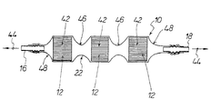
- FIG. 1 shows a diagrammatic view of an embodiment of the filter apparatus
- FIG. 2 shows a graph illustrating the n-butane break-through curve for an adsorption-desorption cycle of a known activated carbon molded body for example in accordance with above-mentioned U.S. Pat. No. 5,914,294 with a relatively small quantity of activated carbon in comparison with a filter apparatus according to the invention
- FIG. 3 shows a diagram illustrating the toluene break-through curve for an adsorption-desorption cycle of an activated carbon molded body in accordance with U.S. Pat. No. 5,914,294 in comparison with a filter apparatus according to the invention
- FIG. 4 shows a diagram illustrating the n-butane break-through curve of an activated carbon molded body in accordance with U.S. Pat. No. 5,914,294 with 35% by weight activated carbon proportion and of a length of 10 cm in comparison with a filter apparatus according to the invention with an activated carbon molded body of the same honeycomb structure with a proportion of activated carbon of 60% by weight and of a length of only 5 cm, and
- FIG. 5 shows the sorption curves of the two mutually compared filter apparatuses for toluene, the test parameters corresponding to the test parameters shown in FIG. 3 .
- FIG. 1 shows an embodiment of the filter apparatus 10 in which the activated carbon shaped or molded body comprises activated carbon body portions 42 which each involve a honeycomb structure, the passages of which are indicated by thin mutually parallel lines.
- the activated carbon body portions 42 are spaced from each other by means of the shrunk shrink tube 22 .
- the shrunk shrink tube 22 bears snugly and sealingly against the connection elements 16 and 18 of the filter apparatus 10 and the activated carbon body portions 42 . It will be appreciated that it is also possible for the activated carbon molded body not to be divided into a number of activated carbon body portions 42 , but to provide only one single activated carbon molded body 12 between the connection elements 16 and 18 .
- the procedure is as follows: the activated carbon body portions 42 are introduced into the brink tube 22 in the non-shrink original condition thereof.
- the shrink tube 22 is then subjected to the action of hot air, with the temperature of the hot air being above the shrinkage temperature of the shrink tube 22 .
- the constricted transitions 48 form halves of paraboloids of the revolution.
- the flexibility of the filter apparatus produced in that way can be adjusted by way of the E-modulus of the shrunk shrink tube 22 .
- the spacing between the activated carbon body portions 42 and between the connection elements 16 , 18 and the activated carbon body portions 42 adjacent thereto can be adjusted by way of the degree of stretching and by virtue of the overall length of the shrink tube 22 used.
- this arrangement ensures homogeneous sealing, over the full area involved, of the activated carbon molded body having a honeycomb structure or the activated carbon body portions having a honeycomb structure, relative to the environment and relative to the connection elements 16 and 18 .
- a quite considerable advantage is afforded by the vibration-damped mounting of the filter apparatus 10 because, with such a vibration-damped mounting arrangement, the mechanical inherent stability of the activated carbon molded body or the activated carbon body portions can be reduced. By virtue of such a reduction in mechanical inherent stability, it is advantageously possible to increase the proportion of activated carbon in the activated carbon molded body or activated carbon body portions, thereby substantially increasing the sorption capacity of the filter apparatus 10 .
- the volume of the filter apparatus 10 makes it possible to reduce the volume of the filter apparatus 10 .
- the filter depth that is to say the dimension of the filter body between its end faces or the dimensions of the activated carbon body portions 42 between their end faces. That permits flexible adaptation to given installation spaces.
- Optimum adaptation to the respective situation of installation in a motor vehicle is possible if the activated carbon molded body 12 is subdivided into activated carbon body portions 42 and if they are put into the form of a flexible tube filter.
- the combination of the fillers clay and glass fiber in conjunction with the glass carbon skeleton affords an activated carbon molded body which is stable in respect of shape.
- the activated carbon molded body is sealingly connected by means of a shrink tube 22 to two connection elements 16 , 18 .
- the shrink tube 22 is a Viton tube with a shrinkage rate of 2:1 at a shrinkage temperature of 175° C.
- FIG. 2 shows the break-through curve of a filter apparatus according to the invention and a honeycomb body in accordance with U.S. Pat. No. 5,914,294, that is to say with only 35% by weight of activated carbon.
- the graph clearly shows how greatly the adsorption capacity decreases in relation to n-butane by virtue of the very much lower proportion of activated carbon.
- the broken line identified by reference numeral 58 represents the n-butane break-through curve of a known activated carbon body in accordance with U.S. Pat. No. 5,914,294 with a proportion of activated carbon of 35% by weight and the solid line identified by reference numeral 60 denotes the n-butane break-through curve of an activated carbon molded body, of the same size, with a honeycomb structure, with a proportion of activated carbon of 60% by weight.
- FIG. 3 shows the break-through curves of the two above-mentioned filters for a sorption test with toluene.
- the solid line identified by reference numeral 60 represents the break-through curve for an adsorption-desorption cycle of a filter apparatus according to the invention with the above-described parameters and the broken line identified by reference numeral 58 represents the corresponding break-through curve of a known activated carbon molded body or honeycomb body in accordance with U.S. Pat. No.
- An activated carbon molded body according to the invention with a proportion of activated carbon of 60% by weight but of a length which is reduced to half, that is to say of a length of 5 cm, and thus being of half the volume, is compared to an activated carbon molded body, that is to say honeycomb body, of the same diameter and of a length of 10 cm in accordance with U.S. Pat. No. 5,914,294, that is to say with a proportion of activated carbon of 35% by weight.
- the corresponding break-through curves for n-butane are illustrated in FIG. 4 .
- the solid line 60 is the break-through curve of the honeycomb body according to the invention of half the volume with a proportion of activated carbon of 60% by weight and the broken line 58 corresponds to the break-through curve 58 shown in FIG. 2 .
- the curves 58 and 60 in FIG. 4 clearly show that, with a correspondingly higher proportion of activated carbon, it is possible to achieve the same adsorption capacity, with a smaller volume.
- FIG. 5 shows the sorption curves of the two filter apparatuses described in comparative terms hereinbefore, for toluene.
- test parameters in regard to toluene afflux flow concentration, air humidity, temperature and volume flow in adsorption and in desorption are the same as the test parameters described with reference to FIG. 3 .
- the curve 62 corresponds to a filter length or depth of 5 cm and the curve 64 corresponds to a filter length or depth of 10 cm. It will be apparent from this Figure that the same sorption capacity can be achieved with a markedly smaller filter volume even for higher-boiling gas like toluene.
Abstract
Description
Claims (3)
Applications Claiming Priority (6)
| Application Number | Priority Date | Filing Date | Title |
|---|---|---|---|
| DE10136318 | 2001-07-26 | ||
| DE10136318 | 2001-07-26 | ||
| DE10136318.4 | 2001-07-26 | ||
| DE10150062A DE10150062B4 (en) | 2001-07-26 | 2001-10-10 | filter means |
| DE10150062.9 | 2001-10-10 | ||
| DE10150062 | 2001-10-10 |
Publications (2)
| Publication Number | Publication Date |
|---|---|
| US20030019361A1 US20030019361A1 (en) | 2003-01-30 |
| US6652629B2 true US6652629B2 (en) | 2003-11-25 |
Family
ID=26009780
Family Applications (1)
| Application Number | Title | Priority Date | Filing Date |
|---|---|---|---|
| US10/202,468 Expired - Lifetime US6652629B2 (en) | 2001-07-26 | 2002-07-24 | Filter apparatus |
Country Status (1)
| Country | Link |
|---|---|
| US (1) | US6652629B2 (en) |
Cited By (9)
| Publication number | Priority date | Publication date | Assignee | Title |
|---|---|---|---|---|
| US20040118287A1 (en) * | 2002-08-13 | 2004-06-24 | Jaffe Stephen Mosheim | Adsorbent sheet material for parallel passage contactors |
| US20060063663A1 (en) * | 2004-07-23 | 2006-03-23 | Helsa-Automotive Gmbh | Adsorptive formed body having an inorganic amorphous supporting structure, and process for the production thereof |
| US20070000389A1 (en) * | 2005-05-16 | 2007-01-04 | Chuck Applegarth | Gas purification with carbon based materials |
| US20070261557A1 (en) * | 2006-05-11 | 2007-11-15 | Gadkaree Kishor P | Activated carbon honeycomb catalyst beds and methods for the use thereof |
| US20090133580A1 (en) * | 2007-11-24 | 2009-05-28 | Dr. Ing. H.C. F. Porsche Aktiengesellschaft | Motor Vehicle |
| US20100047145A1 (en) * | 2008-08-21 | 2010-02-25 | Corning Incorporated | Systems And Methods For Removing Contaminants From Fluid Streams |
| US8535406B2 (en) | 2008-12-18 | 2013-09-17 | 3M Innovative Properties Company | Filter element utilizing shaped particle-containing nonwoven web |
| US20130243675A1 (en) * | 2012-03-14 | 2013-09-19 | Amit Halder | Segmented reactors for carbon dioxide capture and methods of capturing carbon dioxide using segmented reactors |
| US9320996B1 (en) | 2013-10-15 | 2016-04-26 | American Air Filter Company, Inc. | Filter housing utilizing heat shrinkable materials |
Families Citing this family (10)
| Publication number | Priority date | Publication date | Assignee | Title |
|---|---|---|---|---|
| GB0117212D0 (en) * | 2001-07-16 | 2001-09-05 | Mat & Separations Tech Int Ltd | Filter element |
| US6835234B2 (en) * | 2002-12-12 | 2004-12-28 | Visteon Global Technologies, Inc. | Intake tube assembly with evaporative emission control device |
| DE102004063434B4 (en) * | 2004-12-23 | 2009-03-19 | Mann+Hummel Innenraumfilter Gmbh & Co. Kg | Activated carbon moldings, process for its preparation and its use |
| US9568211B1 (en) * | 2013-05-03 | 2017-02-14 | Twist, Inc. | Aircraft air supply hose inline filter |
| EP2946827A1 (en) * | 2014-05-19 | 2015-11-25 | Carl Freudenberg KG | Use of a honeycomb-shaped filter element for adsorbing hydrocarbons |
| FR3058595B1 (en) * | 2016-11-04 | 2019-01-25 | STMicroelectronics (Grand Ouest) SAS | METHOD FOR ADAPTIVELY CONTROLLING A STEP-BY-STEP MOTOR AND CORRESPONDING DEVICE |
| CN107503825A (en) * | 2017-08-22 | 2017-12-22 | 芜湖恒耀汽车零部件有限公司 | A kind of purify cavity of automobile exhaust gas purifying installation |
| DE102018004001A1 (en) * | 2018-05-17 | 2019-11-21 | A. Kayser Automotive Systems Gmbh | Fuel vapor buffer means |
| CN108910878B (en) * | 2018-07-31 | 2021-08-10 | 大连理工大学 | Energy-saving device and method for clean preparation of high-specific-surface-area activated carbon |
| CN111072079A (en) * | 2019-12-25 | 2020-04-28 | 山东赋能康新能源有限公司 | Regulation type sintering active carbon filter core for water purification |
Citations (24)
| Publication number | Priority date | Publication date | Assignee | Title |
|---|---|---|---|---|
| US3019127A (en) * | 1957-10-07 | 1962-01-30 | American Air Filter Co | Filtering medium and method of making the same |
| US3025233A (en) * | 1961-11-03 | 1962-03-13 | Briggs Filtration Co | Filter |
| US3217715A (en) * | 1965-05-24 | 1965-11-16 | American Filtrona Corp | Smoke filter and smoking devices formed therewith |
| US3645072A (en) * | 1970-01-09 | 1972-02-29 | Calgon Corp | Filter and process of making same |
| US3687297A (en) * | 1969-07-04 | 1972-08-29 | Kali Chemie Ag | Shaped body for filtering and drying of liquids and gases and process of making the same |
| US3704806A (en) * | 1971-01-06 | 1972-12-05 | Le T Im Lensoveta | Dehumidifying composition and a method for preparing the same |
| US3721072A (en) * | 1970-07-13 | 1973-03-20 | Calgon Corp | Bonded activated carbon air filter |
| US3919369A (en) * | 1971-03-08 | 1975-11-11 | American Filtrona Corp | Method of manufacturing a self-contained low pressure drop filter |
| US4013566A (en) * | 1975-04-07 | 1977-03-22 | Adsorbex, Incorporated | Flexible desiccant body |
| US4220553A (en) * | 1978-11-20 | 1980-09-02 | Parker-Hannifin Corporation | Method of making filter block of an adsorbent and phenolic-polyurethane binder |
| GB2126123A (en) * | 1982-09-04 | 1984-03-21 | John Charles Cornforth | Adsorbent element |
| US4677086A (en) * | 1984-05-18 | 1987-06-30 | Westvaco Corporation | Shaped wood-based active carbon |
| US4756726A (en) * | 1986-11-20 | 1988-07-12 | Terry Peace | Regenerable dehumidifier |
| DE3838426A1 (en) | 1988-11-12 | 1990-05-17 | Leistritz Ag | EXHAUST GAS PURIFICATION DEVICE |
| US4992084A (en) * | 1988-04-22 | 1991-02-12 | Bluecher Hasso Von | Activated charcoal filter layer for gas masks |
| US5106588A (en) * | 1990-07-30 | 1992-04-21 | General Motors Corporation | Monolithic catalytic converter |
| US5332426A (en) * | 1992-07-29 | 1994-07-26 | Minnesota Mining And Manufacturing Company | Agglomerated activated carbon air filter |
| US5350443A (en) * | 1993-04-19 | 1994-09-27 | Bluecher Hasso Von | Filter sheet material for passenger cabins in motor vehicles |
| US5395428A (en) * | 1990-01-23 | 1995-03-07 | Von Bluecher; Hasso | Filter material for motor vehicles |
| US5456833A (en) * | 1994-05-02 | 1995-10-10 | Selee Corporation | Ceramic foam filter having a protective sleeve |
| US5480621A (en) * | 1988-04-25 | 1996-01-02 | Emitec Gesellschaft Fuer Emissionstechnologie Mbh | Electrically conductive honeycomb as an exhaust gas catalyst carrier body |
| US5914294A (en) | 1996-04-23 | 1999-06-22 | Applied Ceramics, Inc. | Adsorptive monolith including activated carbon and method for making said monlith |
| US6277178B1 (en) * | 1995-01-20 | 2001-08-21 | 3M Innovative Properties Company | Respirator and filter cartridge |
| US6277179B1 (en) * | 1998-06-23 | 2001-08-21 | Ceca S.A. | Agglomerates based on active charcoal, their process of preparation and their use as adsorption agents |
-
2002
- 2002-07-24 US US10/202,468 patent/US6652629B2/en not_active Expired - Lifetime
Patent Citations (27)
| Publication number | Priority date | Publication date | Assignee | Title |
|---|---|---|---|---|
| US3019127A (en) * | 1957-10-07 | 1962-01-30 | American Air Filter Co | Filtering medium and method of making the same |
| US3025233A (en) * | 1961-11-03 | 1962-03-13 | Briggs Filtration Co | Filter |
| US3217715A (en) * | 1965-05-24 | 1965-11-16 | American Filtrona Corp | Smoke filter and smoking devices formed therewith |
| US3687297A (en) * | 1969-07-04 | 1972-08-29 | Kali Chemie Ag | Shaped body for filtering and drying of liquids and gases and process of making the same |
| US3645072A (en) * | 1970-01-09 | 1972-02-29 | Calgon Corp | Filter and process of making same |
| US3721072A (en) * | 1970-07-13 | 1973-03-20 | Calgon Corp | Bonded activated carbon air filter |
| US3704806A (en) * | 1971-01-06 | 1972-12-05 | Le T Im Lensoveta | Dehumidifying composition and a method for preparing the same |
| US3919369A (en) * | 1971-03-08 | 1975-11-11 | American Filtrona Corp | Method of manufacturing a self-contained low pressure drop filter |
| US4013566A (en) * | 1975-04-07 | 1977-03-22 | Adsorbex, Incorporated | Flexible desiccant body |
| US4220553A (en) * | 1978-11-20 | 1980-09-02 | Parker-Hannifin Corporation | Method of making filter block of an adsorbent and phenolic-polyurethane binder |
| GB2126123A (en) * | 1982-09-04 | 1984-03-21 | John Charles Cornforth | Adsorbent element |
| US4677086A (en) * | 1984-05-18 | 1987-06-30 | Westvaco Corporation | Shaped wood-based active carbon |
| US4756726A (en) * | 1986-11-20 | 1988-07-12 | Terry Peace | Regenerable dehumidifier |
| US4992084A (en) * | 1988-04-22 | 1991-02-12 | Bluecher Hasso Von | Activated charcoal filter layer for gas masks |
| US5480621A (en) * | 1988-04-25 | 1996-01-02 | Emitec Gesellschaft Fuer Emissionstechnologie Mbh | Electrically conductive honeycomb as an exhaust gas catalyst carrier body |
| EP0369267A2 (en) * | 1988-11-12 | 1990-05-23 | Leistritz Aktiengesellschaft | Device for the purification of exhaust gas |
| DE3838426A1 (en) | 1988-11-12 | 1990-05-17 | Leistritz Ag | EXHAUST GAS PURIFICATION DEVICE |
| US5395428A (en) * | 1990-01-23 | 1995-03-07 | Von Bluecher; Hasso | Filter material for motor vehicles |
| US5106588A (en) * | 1990-07-30 | 1992-04-21 | General Motors Corporation | Monolithic catalytic converter |
| US5332426A (en) * | 1992-07-29 | 1994-07-26 | Minnesota Mining And Manufacturing Company | Agglomerated activated carbon air filter |
| US5350443A (en) * | 1993-04-19 | 1994-09-27 | Bluecher Hasso Von | Filter sheet material for passenger cabins in motor vehicles |
| US5350443B1 (en) * | 1993-04-19 | 1998-05-05 | Hasso Von Bluecher | Filter sheet material for passenger cabins in motor vehicles |
| US5350443B2 (en) * | 1993-04-19 | 1999-08-10 | Von Hasso Bluecher | Filter sheet material for passenger cabins in motor vehicles |
| US5456833A (en) * | 1994-05-02 | 1995-10-10 | Selee Corporation | Ceramic foam filter having a protective sleeve |
| US6277178B1 (en) * | 1995-01-20 | 2001-08-21 | 3M Innovative Properties Company | Respirator and filter cartridge |
| US5914294A (en) | 1996-04-23 | 1999-06-22 | Applied Ceramics, Inc. | Adsorptive monolith including activated carbon and method for making said monlith |
| US6277179B1 (en) * | 1998-06-23 | 2001-08-21 | Ceca S.A. | Agglomerates based on active charcoal, their process of preparation and their use as adsorption agents |
Cited By (16)
| Publication number | Priority date | Publication date | Assignee | Title |
|---|---|---|---|---|
| US7077891B2 (en) * | 2002-08-13 | 2006-07-18 | Air Products And Chemicals, Inc. | Adsorbent sheet material for parallel passage contactors |
| US20040118287A1 (en) * | 2002-08-13 | 2004-06-24 | Jaffe Stephen Mosheim | Adsorbent sheet material for parallel passage contactors |
| US7759276B2 (en) * | 2004-07-23 | 2010-07-20 | Helsa-Automotive Gmbh & Co. Kg | Adsorptive formed body having an inorganic amorphous supporting structure, and process for the production thereof |
| US20060063663A1 (en) * | 2004-07-23 | 2006-03-23 | Helsa-Automotive Gmbh | Adsorptive formed body having an inorganic amorphous supporting structure, and process for the production thereof |
| US20070000389A1 (en) * | 2005-05-16 | 2007-01-04 | Chuck Applegarth | Gas purification with carbon based materials |
| US7918923B2 (en) * | 2005-05-16 | 2011-04-05 | Saes Getters S.P.A. | Gas purification with carbon based materials |
| US20070261557A1 (en) * | 2006-05-11 | 2007-11-15 | Gadkaree Kishor P | Activated carbon honeycomb catalyst beds and methods for the use thereof |
| US7722705B2 (en) * | 2006-05-11 | 2010-05-25 | Corning Incorporated | Activated carbon honeycomb catalyst beds and methods for the use thereof |
| US20100192769A1 (en) * | 2006-05-11 | 2010-08-05 | Kishor Purushottam Gadkaree | Activated carbon honeycomb catalyst beds and methods for the use thereof |
| US20090133580A1 (en) * | 2007-11-24 | 2009-05-28 | Dr. Ing. H.C. F. Porsche Aktiengesellschaft | Motor Vehicle |
| US7976618B2 (en) | 2007-11-24 | 2011-07-12 | Dr. Ing. H.C. F. Porsche Ag | Motor vehicle |
| US20100047145A1 (en) * | 2008-08-21 | 2010-02-25 | Corning Incorporated | Systems And Methods For Removing Contaminants From Fluid Streams |
| US8535406B2 (en) | 2008-12-18 | 2013-09-17 | 3M Innovative Properties Company | Filter element utilizing shaped particle-containing nonwoven web |
| US20130243675A1 (en) * | 2012-03-14 | 2013-09-19 | Amit Halder | Segmented reactors for carbon dioxide capture and methods of capturing carbon dioxide using segmented reactors |
| US9073000B2 (en) * | 2012-03-14 | 2015-07-07 | Corning Incorporated | Segmented reactors for carbon dioxide capture and methods of capturing carbon dioxide using segmented reactors |
| US9320996B1 (en) | 2013-10-15 | 2016-04-26 | American Air Filter Company, Inc. | Filter housing utilizing heat shrinkable materials |
Also Published As
| Publication number | Publication date |
|---|---|
| US20030019361A1 (en) | 2003-01-30 |
Similar Documents
| Publication | Publication Date | Title |
|---|---|---|
| US6652629B2 (en) | Filter apparatus | |
| EP1113163B1 (en) | Fuel vapor treatment canister | |
| US7976618B2 (en) | Motor vehicle | |
| US7159579B2 (en) | Resilient sling for mounting a carbon monolith in an evaporative emissions canister | |
| US7051717B2 (en) | Evaporative emissions canister having an internal insert | |
| CN100466353C (en) | Engine air cleaner | |
| KR100762051B1 (en) | Method for reducing emissions from evaporative emissions control systems | |
| US5453118A (en) | Carbon-filled fuel vapor filter system | |
| US20060107836A1 (en) | Air filter | |
| CN102032076A (en) | Canister provided with heater | |
| CN1637266A (en) | Canister of vehicle | |
| US20060107835A1 (en) | Air conducting channel | |
| KR20190004800A (en) | Fuel vapor filters for tank ventilation of automobiles with improved charging characteristics | |
| CN201334969Y (en) | Automobile oil filter canister | |
| US11473535B2 (en) | Evaporated fuel treatment device | |
| CN207945023U (en) | A kind of high-effect canister of automobile | |
| US20090318288A1 (en) | Carbon-enriched material | |
| KR100683368B1 (en) | Have a Space Of Canister Automobile | |
| US20160296876A1 (en) | Filter unit for canister | |
| KR20040017053A (en) | Canister of Charge-room have Active Carbon of Multi-layer | |
| JPH01267350A (en) | Fuel evaporation controller for automobile | |
| CN213684340U (en) | Promote carbon tank of engine to carbon desorption rate | |
| KR200232709Y1 (en) | Automotive Fuel Filter | |
| KR200374065Y1 (en) | An Apparatus Of Canister Automobile | |
| CN216588874U (en) | Carbon tank assembly and engine |
Legal Events
| Date | Code | Title | Description |
|---|---|---|---|
| AS | Assignment |
Owner name: HELSA-WERKE HELMUT SANDLER GMBH & CO. KG, GERMANY Free format text: ASSIGNMENT OF ASSIGNORS INTEREST;ASSIGNORS:WOLFF, THOMAS;KRULL, MANFRED;REEL/FRAME:013302/0348 Effective date: 20020806 |
|
| STCF | Information on status: patent grant |
Free format text: PATENTED CASE |
|
| CC | Certificate of correction | ||
| AS | Assignment |
Owner name: HELSA-AUTOMOTIVE GMBH & CO. KG, GERMANY Free format text: ASSIGNMENT OF ASSIGNORS INTEREST;ASSIGNOR:HELSA-WERKE HELMUT SANDLER GMBH & CO. KG;REEL/FRAME:017783/0835 Effective date: 20060330 |
|
| FEPP | Fee payment procedure |
Free format text: PAYOR NUMBER ASSIGNED (ORIGINAL EVENT CODE: ASPN); ENTITY STATUS OF PATENT OWNER: LARGE ENTITY |
|
| FPAY | Fee payment |
Year of fee payment: 4 |
|
| FEPP | Fee payment procedure |
Free format text: PAYER NUMBER DE-ASSIGNED (ORIGINAL EVENT CODE: RMPN); ENTITY STATUS OF PATENT OWNER: LARGE ENTITY Free format text: PAYOR NUMBER ASSIGNED (ORIGINAL EVENT CODE: ASPN); ENTITY STATUS OF PATENT OWNER: LARGE ENTITY |
|
| FPAY | Fee payment |
Year of fee payment: 8 |
|
| FPAY | Fee payment |
Year of fee payment: 12 |