US6635017B1 - Method and apparatus combining diagnostic ultrasound with therapeutic ultrasound to enhance thrombolysis - Google Patents
Method and apparatus combining diagnostic ultrasound with therapeutic ultrasound to enhance thrombolysis Download PDFInfo
- Publication number
- US6635017B1 US6635017B1 US09/500,708 US50070800A US6635017B1 US 6635017 B1 US6635017 B1 US 6635017B1 US 50070800 A US50070800 A US 50070800A US 6635017 B1 US6635017 B1 US 6635017B1
- Authority
- US
- United States
- Prior art keywords
- ultrasound
- diagnostic
- therapeutic
- mode
- administering
- Prior art date
- Legal status (The legal status is an assumption and is not a legal conclusion. Google has not performed a legal analysis and makes no representation as to the accuracy of the status listed.)
- Expired - Lifetime
Links
Images


Classifications
-
- A—HUMAN NECESSITIES
- A61—MEDICAL OR VETERINARY SCIENCE; HYGIENE
- A61B—DIAGNOSIS; SURGERY; IDENTIFICATION
- A61B8/00—Diagnosis using ultrasonic, sonic or infrasonic waves
-
- A—HUMAN NECESSITIES
- A61—MEDICAL OR VETERINARY SCIENCE; HYGIENE
- A61B—DIAGNOSIS; SURGERY; IDENTIFICATION
- A61B8/00—Diagnosis using ultrasonic, sonic or infrasonic waves
- A61B8/08—Detecting organic movements or changes, e.g. tumours, cysts, swellings
- A61B8/0808—Detecting organic movements or changes, e.g. tumours, cysts, swellings for diagnosis of the brain
-
- A—HUMAN NECESSITIES
- A61—MEDICAL OR VETERINARY SCIENCE; HYGIENE
- A61B—DIAGNOSIS; SURGERY; IDENTIFICATION
- A61B17/00—Surgical instruments, devices or methods, e.g. tourniquets
- A61B17/22—Implements for squeezing-off ulcers or the like on the inside of inner organs of the body; Implements for scraping-out cavities of body organs, e.g. bones; Calculus removers; Calculus smashing apparatus; Apparatus for removing obstructions in blood vessels, not otherwise provided for
- A61B17/22004—Implements for squeezing-off ulcers or the like on the inside of inner organs of the body; Implements for scraping-out cavities of body organs, e.g. bones; Calculus removers; Calculus smashing apparatus; Apparatus for removing obstructions in blood vessels, not otherwise provided for using mechanical vibrations, e.g. ultrasonic shock waves
-
- A—HUMAN NECESSITIES
- A61—MEDICAL OR VETERINARY SCIENCE; HYGIENE
- A61B—DIAGNOSIS; SURGERY; IDENTIFICATION
- A61B8/00—Diagnosis using ultrasonic, sonic or infrasonic waves
- A61B8/06—Measuring blood flow
-
- A—HUMAN NECESSITIES
- A61—MEDICAL OR VETERINARY SCIENCE; HYGIENE
- A61B—DIAGNOSIS; SURGERY; IDENTIFICATION
- A61B8/00—Diagnosis using ultrasonic, sonic or infrasonic waves
- A61B8/08—Detecting organic movements or changes, e.g. tumours, cysts, swellings
- A61B8/0833—Detecting organic movements or changes, e.g. tumours, cysts, swellings involving detecting or locating foreign bodies or organic structures
-
- A—HUMAN NECESSITIES
- A61—MEDICAL OR VETERINARY SCIENCE; HYGIENE
- A61B—DIAGNOSIS; SURGERY; IDENTIFICATION
- A61B8/00—Diagnosis using ultrasonic, sonic or infrasonic waves
- A61B8/46—Ultrasonic, sonic or infrasonic diagnostic devices with special arrangements for interfacing with the operator or the patient
- A61B8/461—Displaying means of special interest
- A61B8/463—Displaying means of special interest characterised by displaying multiple images or images and diagnostic data on one display
-
- A—HUMAN NECESSITIES
- A61—MEDICAL OR VETERINARY SCIENCE; HYGIENE
- A61B—DIAGNOSIS; SURGERY; IDENTIFICATION
- A61B8/00—Diagnosis using ultrasonic, sonic or infrasonic waves
- A61B8/48—Diagnostic techniques
- A61B8/481—Diagnostic techniques involving the use of contrast agent, e.g. microbubbles introduced into the bloodstream
-
- A—HUMAN NECESSITIES
- A61—MEDICAL OR VETERINARY SCIENCE; HYGIENE
- A61B—DIAGNOSIS; SURGERY; IDENTIFICATION
- A61B17/00—Surgical instruments, devices or methods, e.g. tourniquets
- A61B17/22—Implements for squeezing-off ulcers or the like on the inside of inner organs of the body; Implements for scraping-out cavities of body organs, e.g. bones; Calculus removers; Calculus smashing apparatus; Apparatus for removing obstructions in blood vessels, not otherwise provided for
- A61B17/225—Implements for squeezing-off ulcers or the like on the inside of inner organs of the body; Implements for scraping-out cavities of body organs, e.g. bones; Calculus removers; Calculus smashing apparatus; Apparatus for removing obstructions in blood vessels, not otherwise provided for for extracorporeal shock wave lithotripsy [ESWL], e.g. by using ultrasonic waves
- A61B17/2256—Implements for squeezing-off ulcers or the like on the inside of inner organs of the body; Implements for scraping-out cavities of body organs, e.g. bones; Calculus removers; Calculus smashing apparatus; Apparatus for removing obstructions in blood vessels, not otherwise provided for for extracorporeal shock wave lithotripsy [ESWL], e.g. by using ultrasonic waves with means for locating or checking the concrement, e.g. X-ray apparatus, imaging means
-
- A—HUMAN NECESSITIES
- A61—MEDICAL OR VETERINARY SCIENCE; HYGIENE
- A61B—DIAGNOSIS; SURGERY; IDENTIFICATION
- A61B90/00—Instruments, implements or accessories specially adapted for surgery or diagnosis and not covered by any of the groups A61B1/00 - A61B50/00, e.g. for luxation treatment or for protecting wound edges
- A61B90/36—Image-producing devices or illumination devices not otherwise provided for
- A61B90/37—Surgical systems with images on a monitor during operation
- A61B2090/378—Surgical systems with images on a monitor during operation using ultrasound
-
- A—HUMAN NECESSITIES
- A61—MEDICAL OR VETERINARY SCIENCE; HYGIENE
- A61B—DIAGNOSIS; SURGERY; IDENTIFICATION
- A61B8/00—Diagnosis using ultrasonic, sonic or infrasonic waves
- A61B8/08—Detecting organic movements or changes, e.g. tumours, cysts, swellings
- A61B8/0808—Detecting organic movements or changes, e.g. tumours, cysts, swellings for diagnosis of the brain
- A61B8/0816—Detecting organic movements or changes, e.g. tumours, cysts, swellings for diagnosis of the brain using echo-encephalography
-
- A—HUMAN NECESSITIES
- A61—MEDICAL OR VETERINARY SCIENCE; HYGIENE
- A61N—ELECTROTHERAPY; MAGNETOTHERAPY; RADIATION THERAPY; ULTRASOUND THERAPY
- A61N7/00—Ultrasound therapy
Definitions
- This invention relates generally to medical diagnostic and therapeutic procedures and devices, and more particularly, to an ultrasound method and apparatus that combines diagnostic ultrasound with therapeutic ultrasound that enhances thrombolysis.
- Thrombosis in the cardiovascular system causes many ailments, for example, stroke, heart attacks, claudication, deep vein thrombosis, and pulmonary embolism.
- stroke clearly compromises quality of life for its victims and for society at large.
- the total cost of stroke reaches billions of dollars each year.
- Direct costs include costs associated with hospital and nursing home stays, treatment by physicians and health professionals, drugs, and home health costs and other medical durables. Indirect costs include costs resulting from lost productivity due to morbidity and lost productivity due to mortality. 1995 data for Americans age 40 and older showed the average in-hospital and physician costs were $11,010 for a stroke and $4,940 for trans-ischemic attack (TIA).
- embolic occlusion generally accounts for 80% of all strokes, and its treatment is grossly different than that for intracerebral hemorrhage (ICH).
- ICH intracerebral hemorrhage
- the origins of embolic stroke are broadly divided into several categories: thrombus dislodged from a variety of sources including ulcerated carotid or aortic plaque, thrombus of cardiac origin, and thrombus of paradoxical origin from the venous system.
- Initial diagnosis of stroke requires radiologic imaging techniques, such as CT or magnetic resonance imaging (MRI), to differentiate between embolic and ICH stroke and to determine the volume of tissue which has had ischemic injury.
- radiologic imaging techniques such as CT or magnetic resonance imaging (MRI)
- MRI magnetic resonance imaging
- a stroke patient is a candidate for thrombolytic therapy if ICH is ruled out, and CT or MRI determines that ischemic changes do not exceed a third of the middle cerebral artery (MCA) territory, blood pressure is normal or controllable, and the diagnosis is made within three hours of onset.
- MCA middle cerebral artery
- ultrasound has been available as a diagnostic modality to assess cerebral hemodynamics
- ultrasound as a therapeutic modality for non-transcranial applications can enhance clot lysis when used in the presence of t-PA
- One reason for the lack of use is due to the high skill level required to acquire and interpret TCD signals using equipment presently on the market and in clinical use. This skill level is not generally available in hospital emergency rooms.
- TCD capabilities in triage and monitoring. For example, the use of ultrasound monitoring to determine the point in time at which thrombolytic therapy re-establishes perfusion (e.g., blood flow through a vessel) is not fully appreciated.
- ultrasound Another reason for the lack of use of ultrasound is that existing instruments cannot conveniently transmit both diagnostic/monitoring and therapeutic ultrasound. Ultrasound is widespread for diagnosis of these illnesses associated with thrombosis, and a device which performs this diagnostic and the new therapeutic modalities would be of clinical use. That is, standard ultrasound instruments are designed solely for transmission of diagnostic/monitoring ultrasound at a given frequency range and cannot be easily switched to therapeutic applications that may require drastically different frequency ranges, lengths of time of application, beam profiles/coverage, or power levels.
- an ultrasound instrument that can be operated by emergency room personnel and that presents easily-interpreted diagnostic blood flow information, but also there is a need for an ultrasound instrument that can be concurrently used to therapeutically treat stroke patients (as well as individuals suffering other types of thrombosis).
- a method of simultaneously treating and monitoring a patient suffering from thrombosis includes positioning a single ultrasound probe proximate a body surface of the patient and administering pulsed ultrasound from the single probe to the patient at a first frequency for a first period of time during a diagnostic mode.
- the method also includes, during a therapeutic mode, administering ultrasound from the single probe to the patient at a second frequency for a second period of time greater than the first period of time to enhance a thrombolytic action of a thrombolytic agent.
- the method also allows for simultaneous application of diagnostic and therapeutic ultrasound, provided the diagnostic receiver can differentiate diagnostic from therapeutic ultrasound echoes.
- a method of treating a patient suffering from thrombosis with ultrasound includes selecting a region on a body surface of the patient and defining a plurality of areas within the region.
- the method includes administering the pulsed ultrasound from a single ultrasound probe to a first one of the areas during a diagnostic mode and evaluating a window through that first area. If the window through the first area is not an optimum window, the method further includes relocating the single ultrasound probe and administering the pulsed ultrasound to a second one of the areas in the diagnostic mode and evaluating a window through the second area, with at least a portion of the second area including at least a portion of the first area.
- the method then repeats administering the pulsed ultrasound to another area in the diagnostic mode if prior areas administered with pulsed ultrasound do not substantially include the optimum window, until an area having substantially the optimum window is located, and then administers the ultrasound in the therapeutic mode from the single ultrasound probe through the area having substantially the optimum window.
- Still another aspect of the invention provides an apparatus to treat a patient suffering from thrombosis with ultrasound by enhancing a thrombolytic action of a thrombolytic agent.
- the apparatus comprises a single ultrasound probe structured to transmit pulsed or continuous-wave ultrasound both in a therapeutic mode and pulsed ultrasound in a diagnostic mode, the ultrasound having a characteristic in the therapeutic mode that is different from a characteristic of the pulsed ultrasound in the diagnostic mode.
- a controller is structured to switch the single ultrasound probe between the diagnostic and therapeutic modes and to process ultrasound Doppler signals returned by the single ultrasound probe during the diagnostic mode.
- a graphical display is responsive to the controller and coupled to the single ultrasound probe.
- the graphical display has a blood locator display structured to depict a plurality of locations along an ultrasound beam axis at which blood flow is detected.
- the blood locator display is responsive to the controller to depict the plurality of locations during the diagnostic mode based on the Doppler signals.
- FIG. 1 is an isometric view of an embodiment of an apparatus and method that combines diagnostic ultrasound with therapeutic ultrasound according to the principles of the present invention.
- FIG. 2 is a diagram showing a first embodiment of an ultrasound probe used in the apparatus of FIG. 1 .
- FIG. 3 is a diagram of a second embodiment of an ultrasound probe that may be used in the apparatus of FIG. 1 .
- FIG. 4 is a graphical diagram depicting a Doppler ultrasound system display mode in accordance with an embodiment of the invention.
- FIG. 5 is a graphical diagram depicting an alternative embodiment of a Doppler ultrasound system display mode in accordance with an embodiment of the invention.
- FIG. 6 is an anatomical schematic of a cranial region of a patient.
- FIG. 7 is a functional block diagram depicting a Doppler ultrasound system in accordance with an embodiment of the invention.
- FIG. 8 is a functional block diagram depicting particular details of pulse Doppler signal processing circuitry included in the Doppler ultrasound system of FIG. 9 .
- FIG. 9 is a schematic diagram of a third embodiment of an ultrasound probe used in the apparatus of FIG. 1 .
- FIG. 10 is a schematic diagram of a fourth embodiment of an ultrasound probe used in the apparatus of FIG. 1 .
- Embodiments of the present invention provide a Doppler ultrasound method and device that monitors cerebral blood flow velocity and concurrently enhances the lysing effect of thrombolytic agents, such as t-PA or urokinase. These embodiments are particularly useful in connection with hospital emergency services.
- embodiments of the invention provide a TCD modality that exists for real-time detection of cerebral blood flow during the early stages of stroke. While embodiments of the invention are generally described herein in the context of transcranial applications, the invention is not limited to this particular application. It will be appreciated that some or all of the principles of the present invention can be applied to cardiac and other components of the cardiovascular system, such as the heart, pulmonary artery and the deep veins of the legs, of a patient affected by thrombosis.
- a vial 110 having a thrombolytic agent (such as t-PA, recombinant t-PA or rt-PA, TNK t-PA, urokinase, or streptokinase) is administered to a patient via a valve 112 and a catheter 114 .
- the catheter 114 injects, introduces, or delivers the thrombolytic agent to a vessel 116 within a body 118 of the patient.
- the thrombolytic agent is shown in FIG.
- the thrombolytic agent can be injected proximate a thrombosis in any conventional manner, including, for example, via hypodermic needles, while the ultrasound is delivered to the site of the thrombus.
- the vessel 116 carries the thrombolytic agent to a thrombosis 122 located in the cranial region 121 , such as when the patient has suffered a stroke.
- the catheter 114 can be positioned within the body 118 such that the vessel 116 carries the thrombolytic agent near a cardiac region 120 in order to treat a thrombosis located in the cardiac region.
- the thrombolytic agent may administered to a leg region 123 of the body 118 in order to treat thrombosis in the deep veins of the leg.
- an ultrasound probe 128 is positioned proximate to a region of the body 118 of the patient where the thrombosis is present.
- FIG. 1 shows the probe 128 positioned near the cardiac region 120 in order to radiate a thrombosis in that respective region, such as in the heart or pulmonary artery.
- the probe 128 may be alternatively positioned near the leg region 123 of the body 118 in order to radiate a thrombosis in that region.
- FIG. 1 further illustrates the probe 128 positioned near the cranial region 121 .
- a head frame 124 is fitted over the cranial region 121 of the patient.
- the head frame 124 includes a mounting attachment 126 structured to hold an ultrasound transducer or probe 128 in place.
- the thrombolytic agent may also be administered and the ultrasound probe 128 may be positioned proximate to other regions of the body 118 where a thrombosis may exist.
- the probe 128 includes a tip 130 that allows ultrasound to be applied transcutaneously or transdermally through a body surface 136 . Specific structural details and associated operating features of the probe 128 will be described in further detail below.
- the probe 128 is coupled to a driver 134 , which can have an adjustable power output ranging from a few milliwatts to a few watts.
- the driver 134 and the probe 128 may be operated such that ultrasound is transmitted at a duty cycle of 100% (e.g., a continuous wave) or pulse-operated at various duty cycles (e.g., at 3% to 80% duty cycles, for example).
- Embodiments of the invention provide pulsed or continuous wave diagnostic and pulsed or continuous wave therapeutic ultrasound.
- Pulsed diagnostic and pulsed therapeutic ultrasound are discussed in this particular embodiment, but one skilled in the art will understand that continuous wave can alternatively be used.
- pulsed ultrasound provides the advantage over continuous-wave of enabling easy spatial discrimination of the blood flow of interest. This diagnostic advantage of pulsed ultrasound is elaborated below.
- FIG. 1 shows that the thrombolytic agent is externally administered from a vial 110 , it is also possible to practice embodiments of the invention without administering an external thrombolytic agent.
- Such embodiments take into account the fact that the human body contains naturally occurring thrombolytic agents in body fluids. Although the concentration of naturally occurring thrombolytic agents is less than a concentration that would be obtained if an external thrombolytic agent is applied, embodiments of the present invention can still use therapeutic ultrasound to enhance the thrombolytic action of the naturally occurring thrombolytic agents.
- FIG. 2 shows an embodiment of the probe 128 that can be used to apply two different ultrasound frequencies to the patient.
- the embodiment of the probe 128 shown in FIG. 2 is used to transmit ultrasound frequencies of approximately 2 MHz during a diagnostic mode to monitor blood flow and 200 kHz during a therapeutic mode to enhance the thrombolytic action of the thrombolytic agent.
- the probe 128 comprises two transducer elements, namely, a 2 MHz crystal 210 and a 200 kHz crystal 212 .
- a dielectric layer 214 separates the crystals 210 and 212 .
- the probe 128 further comprises a damping layer 216 and a potting layer 218 , with the damping layer 216 and the potting layer 218 being disposed on the driver-end of the probe 128 .
- a matching layer 220 is disposed on the patient-end of the probe 128 .
- the embodiment of the probe 128 shown in FIG. 2 is thus a “dual frequency stack” configuration in which the crystal 210 functions as a transducer having a bandwidth range in the vicinity of 2 MHz. Directly behind the crystal 210 is the crystal 212 functioning as a transducer having a bandwidth range in the vicinity of 200 kHz.
- Other frequency pairs besides 2 MHz and 200 kHz can be transmitted by choosing probes 128 having crystals with different frequency ranges. For example, a frequency pair of 100 kHz and 2 MHz or a frequency pair of 1 MHz and 2 MHz can be transmitted.
- different frequency pairs can be transmitted by adjusting the frequency output of the driver 134 such that the output frequencies of the crystals 210 and 212 are slightly varied from their respective 2 MHz and 200 kHz design frequencies. Thus, a frequency pair of 180 kHz and 2 MHz can be transmitted.
- the crystals 210 and 212 can have a diameter of 13 mm, although other diameters, not necessarily equal to each other, can be used depending on the desired focal diameter of the ultrasound beams 222 and 224 .
- the probe 128 shown in FIG. 2 is custom-made for the diagnostic and therapeutic ultrasound applications described herein and is available from Etalon, Inc. of Riverside, Ind. Further, the impedances of the various components 210 - 220 of the probe 128 stack can be designed with matching impedances so as to maximize power transfer and to minimize losses between the components.
- the probe 128 shown in FIG. 2 can produce two ultrasound beams 222 and 224 having different frequencies and shapes.
- the therapeutic beam 222 having a low frequency is transmitted from the crystal 212 .
- the diagnostic beam 224 having a high frequency is transmitted from the crystal 210 .
- the diagnostic beam 224 has a narrower focus or beam shape of the two beams in order to optimize the lateral spatial resolution of the diagnostic beam 224 .
- the therapeutic beam 222 has a wider focus in order to maximize the effective radiation area of the beam in the vicinity of a thrombosis.
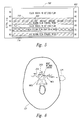
- FIG. 3 An alternative embodiment of the probe 128 is shown in FIG. 3 .
- This embodiment produces therapeutic and diagnostic beams 222 and 224 , respectively, both having the same frequency of 2 MHz (or other frequency).
- the probe 128 comprises two transducer elements annularly arranged into a 7-mm diameter piston transducer element 310 surrounded by an annulus transducer element 312 having an outer diameter of 13 mm.
- This concentric shape allows the probe 128 to be fired on both elements (e.g., the piston 310 and the annulus 312 ) and received on both elements when performing diagnostic measurements of blood flow using the diagnostic beam 224 . Only the piston 310 is fired when transmitting the therapeutic beam 222 at 2 MHz.
- the piston 310 transmits a broader therapeutic beam 222 when activated as a single element during the therapeutic mode.
- the two elements combined transmit the narrower diagnostic beam 224 .
- the embodiment of the probe 128 in FIG. 2 can operate in two frequency regimes to transmit two ultrasound beams having different profiles.
- the same frequency is transmitted by the probe 128 for both diagnostic and therapeutic applications, but the configuration of the probe 128 allows the ultrasound beams 222 and 224 to also have two different shapes.
- the frequencies, number of cycles, intensity, duty cycle, and resulting temporal peak intensity for the ultrasound beams 222 and 224 transmitted by both embodiments of the probe 128 can be varied in order to facilitate an optimum set of parameters to enhance thrombolysis in a particular venue of the body.
- Embodiments of the invention administer therapeutic ultrasound to enhance the lysing effect of a thrombolytic agent.
- Three mechanisms by which ultrasound can potentially enhance thrombolysis in the presence of a thrombolytic agent like t-PA are: “cavitation” (the formation of a bubble via negative pressure, which can in turn cause localized fluid motion), “streaming” and “microstreaming” (conversion of propagating ultrasound energy into fluid motion within tissue), and reversible change of fibrin structure.
- the latter mechanism decreases fibrin matrix flow resistance and increases fibrin binding sites for t-PA.
- the frequencies of this therapeutic ultrasound can be different for these different underlying mechanisms.
- a feature of embodiments of the present invention is that therapeutic ultrasound at higher frequencies (e.g., at 2 MHz) can be used effectively to enhance thrombolysis. This is in direct contrast to conventional approaches that have advocated the use of lower frequencies.
- Therapeutic ultrasound in the present invention is administered in alternating time periods with diagnostic ultrasound. The therapeutic time periods are generally long ( ⁇ 1 minute), after which diagnostic ultrasound is used for a brief ( ⁇ 4 seconds) period to monitor therapeutic progress.
- pulsed ultrasound is performed in vivo at low power levels, such as an average intensity of 50 mW/cm 2 or less, with an intensity level and mode presumed to not induce cavitation or significant streaming.
- low power levels such as an average intensity of 50 mW/cm 2 or less
- the use of low power levels is also in contrast to low frequency literature reports that explore continuous wave ultrasound at high power, in vitro, and that do not utilize transcranial monitoring and treatment from the same probe.
- Spatial peak temporal average ultrasound intensity levels for embodiments of the present invention adhere to industry-agreed upon diagnostic levels to not exceed 720 mW/cm 2 (this is a derated measurement made in water). It will be appreciated that an ultrasound beam with this derated intensity in water will have a much lower intensity in the application of the ultrasound to the middle cerebral artery.
- the lower intensity level is due to reflection and attenuation loss that occurs at the temporal bone, in addition to the attenuation loss through brain tissue.
- Rudimentary calculations using bone attenuation of 40 dB/cm at 2 MHz, brain tissue attenuation of 0.5 dB/cm at 2 MHz, and assuming 3 mm bone thickness and 5 cm of brain tissue show the resulting intensity to be less than 50 mW/cm 2 .
- Embodiments of the invention allow diagnostic ultrasound at 2 MHz to be administered concurrently with therapeutic ultrasound.
- the diagnostic mode of an embodiment of the present invention provides an information display in connection with Doppler ultrasound monitoring of blood flow, such as that described in greater detail in copending U.S. patent application Ser. No. 09/190,402 entitled “DOPPLER ULTRASOUND METHOD AND APPARATUS FOR MONITORING BLOOD FLOW,” filed Nov. 11, 1998, now pending and incorporated by reference.
- FIG. 4 is a graphical diagram depicting a first embodiment of a display mode 600 of Doppler ultrasound information in accordance with one aspect of the invention.
- This display mode 600 is used in connection with aiming the probe 128 .
- this display mode 600 one or both of two distinct ultrasound displays are provided to the user.
- a depth-mode display 602 depicts, with color, blood flow away from and towards the ultrasound probe 128 at various depths along the ultrasound beam axis (vertical axis) as a function of time (horizontal axis).
- the depth-mode display 602 includes colored regions 604 and 606 . Each region is colored either red or blue, where red indicates flow towards the probe 128 and blue indicates flow away from the probe.
- the colored regions are not of uniform color, with the intensity of color varying as a function of the detected intensity of the return Doppler ultrasound signal.
- the display mode 600 can include a displayed spectrogram 608 , with FIG. 6 depicting a velocity envelope showing the characteristic systolic-diastolic pattern.
- the spectrogram 608 includes data points (not shown) within the velocity envelope that are colored in varying intensity as a function of the detected intensity of the return ultrasound signal.
- the particular sample volume for which the spectrogram 608 applies is at a depth indicated in the depth-mode display 602 by depth indicator or pointer 609 . In this way, a user of the ultrasound apparatus 100 can conveniently see and select particular depths at which to measure the spectrogram 608 .
- the depth-mode display 602 readily and conveniently provides the information concerning the range of appropriate depths at which a meaningful spectrogram may be obtained.
- the color intensity of regions 604 and 606 can vary as a function of the detected intensity of the return ultrasound signal.
- Filtering techniques such as clutter filtering, can also be utilized in order to avoid displaying spurious information associated with signals that may be intense but low velocity (such as that due to tissue motion) or with signals having low power (such as that due to noise).
- the depth-mode display 602 employs color intensity mapping as a function of signal intensity, and is further colored red or blue according to flow directions towards or away from the probe 128 , those skilled in the art will appreciate that color intensity as a function of detected velocity may be employed instead. Those skilled in the art will also appreciate that instead of varying color intensity solely as a function of signal amplitude, or solely as a function of velocity, one could advantageously vary color intensity as a function of both signal amplitude and velocity, or use some other data presentation.
- the particularly depicted depth-mode display 602 shows a simplified display of a single, well-defined red region 604 , and a single, well-defined blue region 606 .
- Those skilled in the art will appreciate that the number and characteristics of colored regions will vary depending on the placement and orientation of the probe 128 . Indeed, a catalogue of characteristic depth-mode displays can be provided to assist the user in determining whether a particularly desired blood vessel has, in fact, been located. Once the user finds the characteristic depth-mode display for the desired blood vessel, the user can then conveniently determine the depth at which to measure the spectrogram 608 .
- the display mode 600 enables the user to quickly position the ultrasound probe 128 , such as adjacent to an ultrasound window through the skull (or cranial region 121 ) so that intracranial blood flow can be detected. This procedure will be described later below with reference to FIGS. 9 and 10.
- Use of a colorized representation of signal amplitude is particularly advantageous for this purpose, since a strong signal is indicative of good probe location and orientation. That is, the diagnostic beam 224 is well aimed as the color intensity increases with a volume of moving blood and with the speed of the blood, which as a general rule, occurs when the diagnostic beam is centered on the blood flow.
- FIG. 5 shows a second, alternative embodiment of a display mode 700 , which is to be viewed in conjunction with an anatomical schematic of the cranial region 121 of FIG. 6 .
- the display mode 700 has particular usefulness when viewing blood flow in the cranial region 121 (e.g., a patient suffering from a stroke), although the embodiment shown in FIG. 4 can also be used.
- the display mode 700 only includes the depth-mode display 602 and does not have a spectrogram 608 .
- a simplified user interface is provided for observing middle cerebral circulation by emergency room personnel who do not have expertise in ultrasound.
- FIG. 6 there are three vessels aligned with the axis of the diagnostic beam 224 : the right middle cerebral artery (RMCA), the right anterior cerebral artery (RACA), and the left anterior cerebral artery (LACA).
- FIG. 5 shows three regions 710 , 712 , and 714 , similar to the regions 604 and 606 shown in the display mode 600 of FIG. 4 .
- the regions 710 , 712 , and 714 represent blood flow in the RMCA, RACA, and LACA, respectively, at various depths along the beam axis of the diagnostic beam 224 .
- the region 710 shows blood flow in the RMCA at a 50-mm gate depth, centered along the pointer 609 . Similar to the regions 604 and 606 , the regions 710 , 712 , and 714 have red or blue colors of varying intensities to represent signal intensity, blood flow velocity, a combination of both, or some other representation of data.
- a color m-mode Doppler allows a user to view blood flow at all depths along the beam axis concurrently, rather that at one depth at a time.
- This advantage over single-gate Doppler instruments shortens the time to locate a window through the temporal bone, through which the flow of blood may be observed. Further, blood flow that may be missed due to incorrect gate depth setting for a single gate Doppler will not be missed by the display mode 700 .
- the m-mode is used for localizing occluded vessels where only signals in the region surrounding occluded vessel are appreciated.
- FIG. 7 is a functional block diagram that depicts an ultrasound system 910 in accordance with an embodiment of the invention.
- the ultrasound system 910 produces the various display modes 600 and 700 described above in connection with FIGS. 4 and 5 on an integrated flat panel display 912 , or other desired display format via a display interface connector 914 .
- the signal-processing core of the Doppler ultrasound system 910 is a diagnostic pulse Doppler circuit 916 and a therapeutic pulser circuit 918 . During the diagnostic mode, only the diagnostic pulse Doppler circuit 916 is enabled. During the therapeutic mode, the diagnostic pulse Doppler circuit 916 and the therapeutic pulser circuit 918 may both be enabled simultaneously.
- the Doppler probe 128 is coupled to the diagnostic pulse Doppler 916 and therapeutic pulser circuit 918 .
- the ultrasound system 910 can switch between two separate modes (e.g., a diagnostic mode and a therapeutic mode).
- the diagnostic pulse Doppler circuit 916 receives the ultrasound signals detected by the probe 128 and performs signal and data processing operations, as will be described in detail below. Data is then transmitted to a general-purpose host computer 924 that provides data storage and display.
- a suitable host computer 924 is a 200 MHz Pentium processor-based system having display, keyboard, internal hard disk, and external storage controllers, although any of a variety of suitably adapted computer systems may be employed. While this embodiment utilizes alternating applications of diagnostic and therapeutic ultrasound, one skilled in the art will also appreciate that the invention may also be practiced using simultaneous applications of diagnostic and therapeutic ultrasound if the diagnostic receiver can differentiate diagnostic from therapeutic ultrasound reflections.
- the ultrasound system 910 also provides Doppler audio output signals via audio speakers 926 , as well as via audio lines 928 for storage or for output via an alternative medium.
- the ultrasound system 910 also includes a microphone 930 for receipt of audible information input by the user. This information can then be output for external storage or playback via a voice line 932 .
- the user interfaces with the ultrasound system 910 primarily via a keyboard or other remote input control unit 934 coupled with the host computer 924 .
- operation of the ultrasound system 910 may be performed automatically by programming the host computer 924 to perform such tasks, such as controlling the administration of diagnostic and therapeutic ultrasound.
- a probe 128 having a plurality of transducer elements arranged in an array can be used to locate an optimal probe position for therapeutic ultrasound.
- the host computer 924 can be programmed with suitable pattern recognition software to take advantage of such a probe. After locating the optimal window for administering the ultrasound, the host computer 924 switches to therapeutic mode and administers the therapeutic ultrasound. Additional programming of the host computer 924 for automated operation of the ultrasound system 910 is well known in the art.
- FIG. 8 depicts particular details of the diagnostic pulse Doppler and therapeutic pulser circuits, hereinafter also referred to as the “combined pulser circuit” 916 .
- FIG. 8 also depicts details concerning the input and output of audio information to and from the ultrasound system 910 via the microphone 930 , the speakers 926 , and the audio output lines 928 and 932 , the operations of which are controlled by the diagnostic pulse Doppler circuit 916 .
- the master pulse Doppler circuit 916 includes a transmit/receive switch circuit 1010 operating under control of a timing and control circuit 1012 .
- the particular timing of operations by the diagnostic pulse Doppler circuit 916 and the therapeutic pulser circuit 918 are controlled by the timing and control circuit 1012 of the diagnostic pulse Doppler circuit 916 .
- the timing and control circuit 1012 also controls operation of a diagnostic transmit circuit 1014 (on the master card) that provides an output drive signal that causes the probe 128 to emit the pulsed, ultrasound diagnostic beam 224 during the diagnostic mode.
- the timing and control circuit 1012 further controls operation of a therapeutic transmit circuit 1014 that provides an output drive signal to cause the probe 128 to emit the pulsed ultrasound, therapeutic beam 222 during the therapeutic mode.
- the timing and control circuit 176 additionally controls an analog-to-digital converter circuit 1018 coupled to the transmit/receive switch 1010 by a receiver circuit 1020 .
- the function and operation of circuits 1010 - 1020 are well known to those skilled in the art and need not be described further herein.
- the primary signal processing functions of the diagnostic pulse Doppler circuit 916 are performed by four digital signal processors P 1 -P 4 .
- P 1 is at the front end and receives digitized transducer data from the receiver circuit 1020 via the analog-to-digital converter circuit 1018 and a data buffer or first-in-first-out (FIFO) circuit 1022 .
- P 4 is at the back end and performs higher level tasks such as final display preparation.
- a suitable digital signal processor for P 1 is a Texas Instruments TMS320LC549 integer processor
- suitable digital signal processors for P 2 -P 4 are Texas Instruments TMS320C31 floating point processors, although other digital signal processing circuits may be employed to perform substantially the same functions in accordance with embodiments of the invention.
- Received ultrasound signals are first processed by the digital signal processor P 1 and then passed through the signal-processing pipeline of the digital signal processors P 2 , P 3 , and P 4 .
- the digital signal processor P 1 constructs quadrature vectors from the received digital data, performs filtering operations, and outputs Doppler shift signals associated with 64 different range gate positions.
- the digital signal processor P 2 performs clutter cancellation at all gate depths.
- the digital signal processor P 3 performs a variety of calculations, including autocorrelation, phase, and power calculations. P 3 also provides preparation of the quadrature data for stereo audio output.
- the digital signal processor P 4 performs most of the calculations associated with the spectrogram display and also prepares final calculations associated with preparation of the display modes 600 or 700 .
- Each of the digital signal processors P 1 -P 4 is coupled with the host computer 924 (see, e.g., FIG. 7) via a host bus 1024 and control data buffer circuitry, such as corresponding FIFOs 1026 ( 1 )- 1026 ( 4 ).
- This buffer circuitry allows initialization and program loading of the digital signal processors P 1 -P 4 , as well as other operational communications between the digital signal processors P 1 -P 4 and the host computer 924 .
- Each of the digital signal processors P 1 -P 4 is coupled with an associated high-speed memory or SRAM 1028 ( 1 )- 1028 ( 4 ), which function as program and data memories for the associated signal processors.
- the digital signal processor PI has sufficient internal memory, no external program and data memory SRAM 1028 ( 1 ) need be provided. Transmission of data from one digital signal processor to the next is provided by intervening data buffer or FIFO circuitry 1030 ( 2 )- 1030 ( 4 ). The ultrasound data processed by the digital signal processor P 4 is provided to the host computer 924 via data buffer circuitry such as a dual port SRAM 1032 .
- the digital signal processor P 4 of the diagnostic pulse Doppler circuit 916 also processes audio input via the microphone 930 (which may be coupled to an amplifier 1036 ), as well as controlling provision of the audio output signals to the speakers 926 and audio output lines 928 , 932 .
- P 4 controls the audio output signals by controlling operations of an audio control circuit 1034 , which receives audio signals from both the diagnostic pulse Doppler and the therapeutic pulser circuits 916 and 918 .
- the circuit shown in FIG. 8 may be embodied in two separate cards (e.g., a master card and a slave card) but has been combined in FIG. 8 for simplicity of illustration.
- the master card has substantially all of the elements shown in FIG. 8 except for the therapeutic transmit circuit 1016 .
- the slave card has the therapeutic transmit circuit 1016 (which receives timing and control information from the timing and control circuit 1012 on the master card) and is itself coupled to the host computer 924 via the host bus 1024 .
- the diagnostic pulse Doppler circuit 916 is enabled during the diagnostic mode to transmit the diagnostic beam 224 , and then to process and display the blood flow information.
- the therapeutic pulser circuit 918 is not enabled during the diagnostic mode.
- the timing and control circuit 1012 is operable to switch the ultrasound system 910 alternately between the diagnostic and therapeutic modes, such that the both the diagnostic pulse Doppler circuit 916 and the therapeutic pulser circuit 918 can be enabled during the therapeutic mode. In the therapeutic mode, timing and control circuit 1012 controls the operation of the therapeutic transmit circuit 1016 in order to transmit the therapeutic beam 222 .
- FIG. 9 illustrates another embodiment of a probe 128 to be used in combining diagnostic and therapeutic ultrasound for enhanced thrombolysis.
- the diagnostic and therapeutic frequencies are the same.
- the user is given the ability to locate the temporal window by selecting from a plurality of transducer elements 1112 arranged in an array which substantially cover the temporal bone region, rather than having to reposition a single probe comprised of two transducer elements, as previously described with respect to FIGS. 2 and 3.
- a hexagonal region 1110 is defined as the overall surface of the transducer.
- the region 1110 is comprised of 128 equilateral triangles, intersecting at their vertices 1114 . Each triangle is a transducer element 1112 .
- the 128 triangular transducer elements 1112 are selected for the region 1110 because of the binary nature of the number 128 , and the resulting large hexagonal region maintains good coverage of the human temporal bone territory. However, it will be appreciated that the region 1110 can have any number of triangular elements 1112 by increasing or decreasing the overall size, or changing the size of the basic equilateral triangle unit. Control of the transducer elements 1112 is accomplished through the timing and control functional block 1012 and the transmit/receive switch 1010 . Instead of having two transducer elements to control, as in the probes illustrated in FIGS. 2 and 3, there are a plurality of equilateral triangle elements to control—128 elements in the present example—and utilize in hexagonal groups of six.
- a group of six triangular transducer elements form a hexagonal area 1116 from which the diagnostic beam 224 is initially emitted.
- the lengths of the sides of the triangular elements 1112 are selected such that distances between the vertices of the hexagonal area 1116 are approximately 11 mm.
- the 11-mm “width” of the hexagonal area 1116 is compatible with a circular probe 128 having a similar diameter of 11 mm. It will be appreciated that other sizes for the hexagonal areas may be selected for accomplishing different beam widths for a given frequency.
- the height of the hexagonal region 1110 is approximately 38 mm.
- the horizontal upper and lower sides of the hexagonal region 1110 have lengths of approximately 33 mm, and its diagonal sides have lengths of approximately 22 mm.
- the diagnostic beam emitted from the hexagonal area 1116 has an axis which includes a central point 1118 of the hexagonal area 1116 .
- the resulting Doppler image of the blood flow along that axis is displayed, for example, in the display mode 700 , which was previously described. If the image is unsatisfactory, indicating a poor temporal window, then the diagnostic beam emanating from point 1118 is relocated such that it is aimed from a new point (such as the point 1120 ) adjacent to the central point 1118 .
- triangular elements 39 - 41 and 57 - 59 which define a new hexagonal area 1122 , now become active.
- an advantage of relocating the beam axis to the adjacent point 1120 is that the hexagonal area 1122 will include, or overlap, triangular elements 39 and 57 from the prior hexagonal area 1116 .
- the cranial region 121 can be thoroughly administered with the diagnostic beam in order to find the best temporal window.
- a “picket fence” effect where there are gaps between Doppler images is avoided.
- FIG. 10 Another embodiment of a probe 128 is illustrated in FIG. 10 .
- This embodiment is similar to the probe illustrated in FIG. 9, except that instead of triangular transducer elements 1112 arranged in a hexagonal region 1110 , the plurality of transducer elements are arranged in a polygonal region 1210 , where each of the squares represents a transducer element 1212 .
- the square elements 1212 are joined together at a plurality of points 1214 .
- the diagnostic beam is radiated from a square region 1216 , defined by the activated square elements 30 - 31 and 43 - 44 , and centered about the point 1218 .
- the diagnostic beam can then be sequentially relocated to an adjacent point 1220 , such that the ultrasound beam is emitted from square elements 31 - 32 and 44 - 45 of a square region 1222 , for example.
- the square elements 31 and 44 form the overlapping regions with the initial square region 1216 .
- the embodiments of the probes 128 shown in FIGS. 9 and 10 further include the capability of steering the beam emanating from a particular point 1118 or 1218 by electronically phasing the associated radiating elements. Steering the beam accommodates the fact that the blood flow and the beam center ( 1118 or 1218 ) do not necessarily lie on an axis perpendicular to the transducer face. Such a method of steering the ultrasound beam is well understood to one skilled in the art, and a more detailed explanation has been omitted in the interests of brevity.
- the host computer 924 may be programmed to carry out the procedure previously described using the probe 128 illustrated in FIGS. 9 and 10. Automating the ultrasound system in such a fashion allows useful results to be obtained by those who are not trained experts in ultrasound. As mentioned previously, the host computer may be programmed with conventional pattern recognition software to interpret the resulting Doppler image of the blood flow and determine an optimal temporal window. After locating the optimal window, the host computer 924 administers pulsed ultrasound in a therapeutic mode. Although automation of the ultrasound system has been described with respect to administering diagnostic and therapeutic ultrasound in transcranial applications, it will be appreciated that a computer controlled ultrasound system may be applied to cardiac and other physiological systems as well.
Abstract
Description
Claims (58)
Priority Applications (10)
| Application Number | Priority Date | Filing Date | Title |
|---|---|---|---|
| US09/500,708 US6635017B1 (en) | 2000-02-09 | 2000-02-09 | Method and apparatus combining diagnostic ultrasound with therapeutic ultrasound to enhance thrombolysis |
| PCT/US2001/003575 WO2001058337A2 (en) | 2000-02-09 | 2001-02-02 | Method and apparatus combining diagnostic ultrasound with therapeutic ultrasound to enhance thrombolysis |
| KR1020027010315A KR20030036137A (en) | 2000-02-09 | 2001-02-02 | Method and apparatus combining diagnostic ultrasound with therapeutic ultrasound to enhance thrombolysis |
| AU3329501A AU3329501A (en) | 2000-02-09 | 2001-02-02 | Method and apparatus combining diagnostic ultrasound with therapeutic ultrasoundto enhance thrombolysis |
| JP2001557454A JP2003534032A (en) | 2000-02-09 | 2001-02-02 | Method and apparatus for enhancing thrombolysis by combining diagnostic and therapeutic ultrasound |
| CA002399410A CA2399410A1 (en) | 2000-02-09 | 2001-02-02 | Method and apparatus combining diagnostic ultrasound with therapeutic ultrasound to enhance thrombolysis |
| AU2001233295A AU2001233295B2 (en) | 2000-02-09 | 2001-02-02 | Method and apparatus combining diagnostic ultrasound with therapeutic ultra-sound to enhance thrombolysis |
| EP01905414A EP1255488A4 (en) | 2000-02-09 | 2001-02-02 | Method and apparatus combining diagnostic ultrasound with therapeutic ultrasound to enhance thrombolysis |
| US10/691,122 US7425198B2 (en) | 2000-02-09 | 2003-10-21 | Method and apparatus for automatic location of blood flow with Doppler ultrasound |
| AU2005220207A AU2005220207A1 (en) | 2000-02-09 | 2005-10-06 | Method and apparatus combining diagnostic ultrasound with therapeutic ultrasound to enhance thrombolysis |
Applications Claiming Priority (1)
| Application Number | Priority Date | Filing Date | Title |
|---|---|---|---|
| US09/500,708 US6635017B1 (en) | 2000-02-09 | 2000-02-09 | Method and apparatus combining diagnostic ultrasound with therapeutic ultrasound to enhance thrombolysis |
Related Child Applications (1)
| Application Number | Title | Priority Date | Filing Date |
|---|---|---|---|
| US10/691,122 Continuation US7425198B2 (en) | 2000-02-09 | 2003-10-21 | Method and apparatus for automatic location of blood flow with Doppler ultrasound |
Publications (1)
| Publication Number | Publication Date |
|---|---|
| US6635017B1 true US6635017B1 (en) | 2003-10-21 |
Family
ID=23990578
Family Applications (2)
| Application Number | Title | Priority Date | Filing Date |
|---|---|---|---|
| US09/500,708 Expired - Lifetime US6635017B1 (en) | 2000-02-09 | 2000-02-09 | Method and apparatus combining diagnostic ultrasound with therapeutic ultrasound to enhance thrombolysis |
| US10/691,122 Expired - Lifetime US7425198B2 (en) | 2000-02-09 | 2003-10-21 | Method and apparatus for automatic location of blood flow with Doppler ultrasound |
Family Applications After (1)
| Application Number | Title | Priority Date | Filing Date |
|---|---|---|---|
| US10/691,122 Expired - Lifetime US7425198B2 (en) | 2000-02-09 | 2003-10-21 | Method and apparatus for automatic location of blood flow with Doppler ultrasound |
Country Status (7)
| Country | Link |
|---|---|
| US (2) | US6635017B1 (en) |
| EP (1) | EP1255488A4 (en) |
| JP (1) | JP2003534032A (en) |
| KR (1) | KR20030036137A (en) |
| AU (3) | AU2001233295B2 (en) |
| CA (1) | CA2399410A1 (en) |
| WO (1) | WO2001058337A2 (en) |
Cited By (96)
| Publication number | Priority date | Publication date | Assignee | Title |
|---|---|---|---|---|
| US20020049395A1 (en) * | 2000-08-24 | 2002-04-25 | Timi 3 | Systems for applying ultrasound energy to the thoracic cavity |
| US20020072691A1 (en) * | 2000-08-24 | 2002-06-13 | Timi 3 Systems, Inc. | Systems and methods for applying ultrasonic energy to the thoracic cavity |
| US20020082529A1 (en) * | 2000-08-24 | 2002-06-27 | Timi 3 Systems, Inc. | Systems and methods for applying pulsed ultrasonic energy |
| US20020091339A1 (en) * | 2000-08-24 | 2002-07-11 | Timi 3 Systems, Inc. | Systems and methods for applying ultrasound energy to stimulating circulatory activity in a targeted body region of an individual |
| US20020159952A1 (en) * | 1997-05-13 | 2002-10-31 | Unger Evan C. | Novel acoustically active drug delivery systems |
| US20020183771A1 (en) * | 2001-03-28 | 2002-12-05 | Vascular Control Systems, Inc. | Method and apparatus for the detection and ligation of uterine arteries |
| US20030003055A1 (en) * | 1989-12-22 | 2003-01-02 | Unger Evan C. | Methods of preparing gaseous precursor-filled microspheres |
| US20030012735A1 (en) * | 1996-06-19 | 2003-01-16 | Unger Evan C. | Methods for diagnostic imaging by regulating the administration rate of contrast agent |
| US20030044354A1 (en) * | 2001-08-16 | 2003-03-06 | Carpenter Alan P. | Gas microsphere liposome composites for ultrasound imaging and ultrasound stimulated drug release |
| US20030050560A1 (en) * | 2000-08-24 | 2003-03-13 | Timi 3 Systems, Inc. | Systems and methods for delivering ultrasonic energy |
| US20030055363A1 (en) * | 2000-08-24 | 2003-03-20 | Timi 3 Systems, Inc. | Systems and methods for monitoring and enabling use of a medical instrument |
| US20030069526A1 (en) * | 2000-08-24 | 2003-04-10 | Timi 3 Systems, Inc. | Applicators that house and support ultrasound transducers for transcutaneous delivery of ultrasound energy |
| US20040019278A1 (en) * | 2000-05-26 | 2004-01-29 | Kenneth Abend | Device and method for mapping and tracking blood flow and determining parameters of blood flow |
| US20040057991A1 (en) * | 1998-01-14 | 2004-03-25 | Hui Poh K. | Preparation of a lipid blend and a phospholipid suspension containing the lipid blend |
| US20040073115A1 (en) * | 2000-08-24 | 2004-04-15 | Timi 3 Systems, Inc. | Systems and methods for applying ultrasound energy to increase tissue perfusion and/or vasodilation without substantial deep heating of tissue |
| US20040138563A1 (en) * | 2000-02-09 | 2004-07-15 | Moehring Mark A | Method and apparatus combining diagnostic ultrasound with therapeutic ultrasound to enhance thrombolysis |
| US20040153009A1 (en) * | 2003-02-05 | 2004-08-05 | Timi 3 Systems, Inc. | Systems and methods for applying audible acoustic energy to increase tissue perfusion and/or vasodilation |
| US20040230117A1 (en) * | 2003-04-17 | 2004-11-18 | Tosaya Carol A. | Non-contact damage-free ultrasonic cleaning of implanted or natural structures having moving parts and located in a living body |
| US20040267127A1 (en) * | 1999-05-28 | 2004-12-30 | Vuesonix Sensors, Inc. | Transmitter patterns for multi beam reception |
| US20040267120A1 (en) * | 2003-06-30 | 2004-12-30 | Ethicon, Inc. | Method and instrumentation to sense thermal lesion formation by ultrasound imaging |
| US20050015009A1 (en) * | 2000-11-28 | 2005-01-20 | Allez Physionix , Inc. | Systems and methods for determining intracranial pressure non-invasively and acoustic transducer assemblies for use in such systems |
| US20050019744A1 (en) * | 2003-07-25 | 2005-01-27 | La Jolla Bioengineering Institute | Ultrasound-assisted ischemic reperfusion |
| US20050033174A1 (en) * | 2003-07-10 | 2005-02-10 | Moehring Mark A. | Doppler ultrasound method and apparatus for monitoring blood flow and hemodynamics |
| US20050054958A1 (en) * | 2003-09-04 | 2005-03-10 | Hoffmann Andrew Kenneth | Low frequency vibration assisted blood perfusion emergency system |
| US20050075568A1 (en) * | 1998-11-11 | 2005-04-07 | Moehring Mark A. | Doppler ultrasound method and apparatus for monitoring blood flow |
| US20050240151A1 (en) * | 2004-01-29 | 2005-10-27 | Hansmann Douglas R | Treatment of vascular occlusions using elevated temperatures |
| WO2006010240A1 (en) * | 2004-07-30 | 2006-02-02 | Ahof Biophysical Systems Inc. | Hand-held imaging probe for treatment of states of low blood perfusion |
| US20060106425A1 (en) * | 2004-11-15 | 2006-05-18 | Dennis Leuer | Method and apparatus of removal of intravascular blockages |
| US20060123043A1 (en) * | 2004-12-02 | 2006-06-08 | Samsung Electronics Co., Ltd. | File system path processing device and method |
| US20060173321A1 (en) * | 2003-01-31 | 2006-08-03 | Jun Kubota | Ultrasonic probe and ultrasonic device |
| US20060211955A1 (en) * | 2000-08-24 | 2006-09-21 | Horzewski Michael J | Systems and methods for applying ultrasound energy to stimulating circulatory activity in a targeted body region of an individual |
| US20060264759A1 (en) * | 2005-05-20 | 2006-11-23 | Moehring Mark A | System and method for grading microemboli monitored by a multi-gate doppler ultrasound system |
| US20070016050A1 (en) * | 2005-06-13 | 2007-01-18 | Moehring Mark A | Medical Doppler ultrasound system for locating and tracking blood flow |
| US20070088379A1 (en) * | 2005-10-17 | 2007-04-19 | Jacob Schneiderman | Minimally invasive a AAPT extirpation |
| US20070260172A1 (en) * | 1999-02-16 | 2007-11-08 | Henry Nita | Pre-shaped therapeutic catheter |
| US7335169B2 (en) | 2000-08-24 | 2008-02-26 | Timi 3 Systems, Inc. | Systems and methods for delivering ultrasound energy at an output power level that remains essentially constant despite variations in transducer impedance |
| US7354444B2 (en) * | 2001-03-28 | 2008-04-08 | Vascular Control Systems, Inc. | Occlusion device with deployable paddles for detection and occlusion of blood vessels |
| US20080108937A1 (en) * | 2006-11-07 | 2008-05-08 | Henry Nita | Ultrasound catheter having protective feature against breakage |
| US20080154181A1 (en) * | 2006-05-05 | 2008-06-26 | Khanna Rohit K | Central nervous system ultrasonic drain |
| US20080172067A1 (en) * | 2003-11-24 | 2008-07-17 | Flowcardia, Inc. | Steerable ultrasound catheter |
| US20080208084A1 (en) * | 2003-02-05 | 2008-08-28 | Timi 3 Systems, Inc. | Systems and methods for applying ultrasound energy to increase tissue perfusion and/or vasodilation without substantial deep heating of tissue |
| US20090048544A1 (en) * | 2007-08-16 | 2009-02-19 | Andrey Rybyanets | Apparatus and method for ultrasound treatment |
| US20090222035A1 (en) * | 2006-03-27 | 2009-09-03 | Tel Hashomer Medical Research Infrastructure And S | Intraluminal Mass Collector |
| US20090318813A1 (en) * | 2000-08-24 | 2009-12-24 | Timi 3 Systems, Inc. | Applicators that house and support ultrasound transducers for transcutaneou delivery of ultrasound energy |
| US7651511B2 (en) * | 2003-02-05 | 2010-01-26 | Vascular Control Systems, Inc. | Vascular clamp for caesarian section |
| US7727178B2 (en) | 2001-12-03 | 2010-06-01 | Ekos Corporation | Catheter with multiple ultrasound radiating members |
| US7771372B2 (en) | 2003-01-03 | 2010-08-10 | Ekos Corporation | Ultrasonic catheter with axial energy field |
| US20100222723A1 (en) * | 2003-09-04 | 2010-09-02 | Ahof Biophysical Systems Inc. | Vibration method for clearing acute arterial thrombotic occlusions in the emergency treatment of heart attack and stroke |
| US7875036B2 (en) | 2004-10-27 | 2011-01-25 | Vascular Control Systems, Inc. | Short term treatment for uterine disorder |
| US7955293B2 (en) | 2002-08-26 | 2011-06-07 | Flowcardia, Inc. | Ultrasound catheter for disrupting blood vessel obstructions |
| US8002736B2 (en) | 2007-12-21 | 2011-08-23 | Carticept Medical, Inc. | Injection systems for delivery of fluids to joints |
| US8043251B2 (en) * | 2003-01-14 | 2011-10-25 | Flowcardia, Inc. | Ultrasound catheter and methods for making and using same |
| US8062566B2 (en) | 2003-04-08 | 2011-11-22 | Flowcardia, Inc. | Method of manufacturing an ultrasound transmission member for use in an ultrasound catheter device |
| US8192363B2 (en) | 2006-10-27 | 2012-06-05 | Ekos Corporation | Catheter with multiple ultrasound radiating members |
| US8192391B2 (en) | 2009-07-03 | 2012-06-05 | Ekos Corporation | Power parameters for ultrasonic catheter |
| US8221343B2 (en) | 2005-01-20 | 2012-07-17 | Flowcardia, Inc. | Vibrational catheter devices and methods for making same |
| US20120184854A1 (en) * | 2009-02-24 | 2012-07-19 | Koninklijke Philips Electronics N.V. | Ultrasonic vascular flow sensor with triangular sensor geometry |
| US8226566B2 (en) | 2009-06-12 | 2012-07-24 | Flowcardia, Inc. | Device and method for vascular re-entry |
| US8226629B1 (en) | 2002-04-01 | 2012-07-24 | Ekos Corporation | Ultrasonic catheter power control |
| US8246643B2 (en) | 2006-11-07 | 2012-08-21 | Flowcardia, Inc. | Ultrasound catheter having improved distal end |
| US8317776B2 (en) | 2007-12-18 | 2012-11-27 | The Invention Science Fund I, Llc | Circulatory monitoring systems and methods |
| US8353853B1 (en) * | 2003-01-24 | 2013-01-15 | Boston Scientific Scimed, Inc. | Encephalic insonication |
| US20130023786A1 (en) * | 2010-04-08 | 2013-01-24 | Koninklijke Philips Electronics N.V. | Predicting urination |
| US8409132B2 (en) | 2007-12-18 | 2013-04-02 | The Invention Science Fund I, Llc | Treatment indications informed by a priori implant information |
| US8545440B2 (en) | 2007-12-21 | 2013-10-01 | Carticept Medical, Inc. | Injection system for delivering multiple fluids within the anatomy |
| US20130281897A1 (en) * | 2003-09-04 | 2013-10-24 | Ahof Biophysical Systems Inc. | Non-invasive reperfusion system by deformation of remote, superficial arteries at a frequency much greater than the pulse rate |
| US8617096B2 (en) | 2004-08-26 | 2013-12-31 | Flowcardia, Inc. | Ultrasound catheter devices and methods |
| US8636670B2 (en) | 2008-05-13 | 2014-01-28 | The Invention Science Fund I, Llc | Circulatory monitoring systems and methods |
| US8641630B2 (en) | 2003-09-19 | 2014-02-04 | Flowcardia, Inc. | Connector for securing ultrasound catheter to transducer |
| US8647293B2 (en) | 2002-08-02 | 2014-02-11 | Flowcardia, Inc. | Therapeutic ultrasound system |
| US8721573B2 (en) | 2003-09-04 | 2014-05-13 | Simon Fraser University | Automatically adjusting contact node for multiple rib space engagement |
| US8734368B2 (en) | 2003-09-04 | 2014-05-27 | Simon Fraser University | Percussion assisted angiogenesis |
| US8740835B2 (en) | 2010-02-17 | 2014-06-03 | Ekos Corporation | Treatment of vascular occlusions using ultrasonic energy and microbubbles |
| US20150025380A1 (en) * | 2012-04-13 | 2015-01-22 | Kabushiki Kaisha Toshiba | Ultrasound diagnosis apparatus, image processing apparatus and image processing method |
| US8961423B2 (en) | 2003-02-26 | 2015-02-24 | Flowcardia, Inc. | Ultrasound catheter apparatus |
| US9044542B2 (en) | 2007-12-21 | 2015-06-02 | Carticept Medical, Inc. | Imaging-guided anesthesia injection systems and methods |
| US9107590B2 (en) | 2004-01-29 | 2015-08-18 | Ekos Corporation | Method and apparatus for detecting vascular conditions with a catheter |
| US9282984B2 (en) | 2006-04-05 | 2016-03-15 | Flowcardia, Inc. | Therapeutic ultrasound system |
| US9457201B2 (en) * | 2012-05-11 | 2016-10-04 | The Regents Of The University Of California | Portable device to initiate and monitor treatment of stroke victims in the field |
| US20170196465A1 (en) * | 2006-08-11 | 2017-07-13 | Koninklijke Philips N.V. | Ultrasound system for cerebral blood flow imaging and microbubble-enhanced blood clot lysis |
| US10092742B2 (en) | 2014-09-22 | 2018-10-09 | Ekos Corporation | Catheter system |
| US10182833B2 (en) | 2007-01-08 | 2019-01-22 | Ekos Corporation | Power parameters for ultrasonic catheter |
| US10188410B2 (en) | 2007-01-08 | 2019-01-29 | Ekos Corporation | Power parameters for ultrasonic catheter |
| US10357263B2 (en) | 2012-01-18 | 2019-07-23 | C. R. Bard, Inc. | Vascular re-entry device |
| US10582983B2 (en) | 2017-02-06 | 2020-03-10 | C. R. Bard, Inc. | Ultrasonic endovascular catheter with a controllable sheath |
| US10656025B2 (en) | 2015-06-10 | 2020-05-19 | Ekos Corporation | Ultrasound catheter |
| US10758256B2 (en) | 2016-12-22 | 2020-09-01 | C. R. Bard, Inc. | Ultrasonic endovascular catheter |
| US10835267B2 (en) | 2002-08-02 | 2020-11-17 | Flowcardia, Inc. | Ultrasound catheter having protective feature against breakage |
| CN112370079A (en) * | 2020-11-18 | 2021-02-19 | 景德镇陶瓷大学 | Method for detecting thrombus by using ultrasonic Doppler |
| US11154273B2 (en) * | 2018-01-11 | 2021-10-26 | Novasignal Corp. | Systems and methods for vascular mapping |
| US11344750B2 (en) | 2012-08-02 | 2022-05-31 | Flowcardia, Inc. | Ultrasound catheter system |
| US11458290B2 (en) | 2011-05-11 | 2022-10-04 | Ekos Corporation | Ultrasound system |
| US11596726B2 (en) | 2016-12-17 | 2023-03-07 | C.R. Bard, Inc. | Ultrasound devices for removing clots from catheters and related methods |
| US11633206B2 (en) | 2016-11-23 | 2023-04-25 | C.R. Bard, Inc. | Catheter with retractable sheath and methods thereof |
| US11672553B2 (en) | 2007-06-22 | 2023-06-13 | Ekos Corporation | Method and apparatus for treatment of intracranial hemorrhages |
| US11872413B2 (en) * | 2017-06-19 | 2024-01-16 | Assistance Publique Hopitaux De Paris | Control method for the treatment of brain tissue using an ultrasonic probe and an implanted acoustic window on the cranium |
Families Citing this family (64)
| Publication number | Priority date | Publication date | Assignee | Title |
|---|---|---|---|---|
| US6618620B1 (en) | 2000-11-28 | 2003-09-09 | Txsonics Ltd. | Apparatus for controlling thermal dosing in an thermal treatment system |
| DE60329986D1 (en) * | 2002-03-15 | 2009-12-24 | Bjorn A J Angelsen | ULTRASONIC DISPLAY OF OBJECTS IN MULTIPLE SCANEBENES |
| US8206304B1 (en) * | 2003-12-16 | 2012-06-26 | Vascular Technology Incorporated | Doppler transceiver and probe for use in minimally invasive procedures |
| US20060241425A1 (en) * | 2004-03-29 | 2006-10-26 | Qinetiq Limited | Ultrasound detection |
| WO2005122933A1 (en) * | 2004-06-21 | 2005-12-29 | Hiroshi Furuhata | Ultrasonic brain infarction treating device |
| WO2006117923A1 (en) * | 2005-04-26 | 2006-11-09 | Kobe Material Testing Laboratory Co., Ltd. | System of diagnosing and treating the interior of blood vessel by ultrasonic wave |
| JP2006305047A (en) * | 2005-04-28 | 2006-11-09 | Hitachi Medical Corp | Ultrasound treatment system and ultrasonic diagnostic system |
| JP2008539908A (en) * | 2005-05-12 | 2008-11-20 | コンピュメディクス メディカル イノベーション ピーティーワイ リミテッド | Ultrasound diagnostic and treatment equipment |
| US7717853B2 (en) * | 2005-06-24 | 2010-05-18 | Henry Nita | Methods and apparatus for intracranial ultrasound delivery |
| US20070016040A1 (en) * | 2005-06-24 | 2007-01-18 | Henry Nita | Methods and apparatus for intracranial ultrasound delivery |
| US20110160621A1 (en) * | 2005-06-24 | 2011-06-30 | Henry Nita | Methods and apparatus for dissolving intracranial blood clots |
| US8057408B2 (en) * | 2005-09-22 | 2011-11-15 | The Regents Of The University Of Michigan | Pulsed cavitational ultrasound therapy |
| US10219815B2 (en) * | 2005-09-22 | 2019-03-05 | The Regents Of The University Of Michigan | Histotripsy for thrombolysis |
| US20070083120A1 (en) * | 2005-09-22 | 2007-04-12 | Cain Charles A | Pulsed cavitational ultrasound therapy |
| US20070167798A1 (en) * | 2005-11-23 | 2007-07-19 | Cai Anming H | Contrast agent augmented ultrasound therapy system with ultrasound imaging guidance for thrombus treatment |
| US7758505B2 (en) * | 2006-04-03 | 2010-07-20 | Elfi-Tech Ltd. | Methods and apparatus for non-invasive determination of patient's blood conditions |
| KR100792658B1 (en) * | 2006-07-19 | 2008-01-09 | 주식회사 에스앤지바이오텍 | Device for dissolving thrombus in blood vessel by magnetostrictive vibrator |
| EP2053974A2 (en) | 2006-08-08 | 2009-05-06 | Keter Medical Ltd. | Imaging system |
| EP2255847A1 (en) * | 2006-08-11 | 2010-12-01 | Koninklijke Philips Electronics N.V. | Ultrasound system for cerebral blood flow monitoring |
| CN101313855B (en) * | 2007-06-01 | 2010-06-16 | 深圳市德力凯电子有限公司 | Method for automatic detection of brain bloodstream |
| CN100566663C (en) * | 2007-06-01 | 2009-12-09 | 深圳市德力凯电子有限公司 | A kind of probe frame for brain bloodstream detection |
| WO2009021535A1 (en) * | 2007-08-14 | 2009-02-19 | Campus Micro Technologies Gmbh | Medical devices, systems and methods for blood pressure regulation |
| WO2009094554A2 (en) * | 2008-01-25 | 2009-07-30 | The Regents Of The University Of Michigan | Histotripsy for thrombolysis |
| US20090312673A1 (en) * | 2008-06-14 | 2009-12-17 | Vytronus, Inc. | System and method for delivering energy to tissue |
| TWM354841U (en) * | 2008-08-22 | 2009-04-11 | Wistron Corp | Waterproof pushbutton, and the assembly of waterproof pushbutton and electronic device housing |
| US8425424B2 (en) * | 2008-11-19 | 2013-04-23 | Inightee Ltd. | Closed-loop clot lysis |
| US9623266B2 (en) | 2009-08-04 | 2017-04-18 | Insightec Ltd. | Estimation of alignment parameters in magnetic-resonance-guided ultrasound focusing |
| AU2010284313B2 (en) | 2009-08-17 | 2016-01-28 | Histosonics, Inc. | Disposable acoustic coupling medium container |
| JP5726191B2 (en) | 2009-08-26 | 2015-05-27 | リージェンツ オブ ザ ユニバーシティー オブ ミシガン | Apparatus and method using control of bubble turbidity cavitation phenomenon during fracture of ureteral stones |
| US9177543B2 (en) | 2009-08-26 | 2015-11-03 | Insightec Ltd. | Asymmetric ultrasound phased-array transducer for dynamic beam steering to ablate tissues in MRI |
| WO2011028603A2 (en) | 2009-08-26 | 2011-03-10 | The Regents Of The University Of Michigan | Micromanipulator control arm for therapeutic and imaging ultrasound transducers |
| US8539813B2 (en) | 2009-09-22 | 2013-09-24 | The Regents Of The University Of Michigan | Gel phantoms for testing cavitational ultrasound (histotripsy) transducers |
| US9375223B2 (en) | 2009-10-06 | 2016-06-28 | Cardioprolific Inc. | Methods and devices for endovascular therapy |
| US8932237B2 (en) | 2010-04-28 | 2015-01-13 | Insightec, Ltd. | Efficient ultrasound focusing |
| US9852727B2 (en) | 2010-04-28 | 2017-12-26 | Insightec, Ltd. | Multi-segment ultrasound transducers |
| JP2012000194A (en) * | 2010-06-15 | 2012-01-05 | Hitachi Aloka Medical Ltd | Medical system |
| US8622912B2 (en) | 2010-07-13 | 2014-01-07 | Fabrico Technology, Inc. | Transcranial doppler apparatus |
| US9981148B2 (en) | 2010-10-22 | 2018-05-29 | Insightec, Ltd. | Adaptive active cooling during focused ultrasound treatment |
| JP5192532B2 (en) * | 2010-11-18 | 2013-05-08 | 学校法人慈恵大学 | Medical ultrasonic transducer |
| KR101313220B1 (en) * | 2010-11-23 | 2013-09-30 | 삼성메디슨 주식회사 | Ultrasound system and method for providing color doppler mode image based on qualification curve |
| US9144694B2 (en) | 2011-08-10 | 2015-09-29 | The Regents Of The University Of Michigan | Lesion generation through bone using histotripsy therapy without aberration correction |
| FR2987275B1 (en) * | 2012-02-24 | 2015-04-03 | Advance Beauty | APPARATUS FOR TREATING SKIN WITH ULTRASONIC SEQUENCES |
| US9049783B2 (en) | 2012-04-13 | 2015-06-02 | Histosonics, Inc. | Systems and methods for obtaining large creepage isolation on printed circuit boards |
| WO2013163605A1 (en) * | 2012-04-26 | 2013-10-31 | Dbmedx Inc. | Ultrasound apparatus and methods to monitor bodily vessels |
| EP2844343B1 (en) | 2012-04-30 | 2018-11-21 | The Regents Of The University Of Michigan | Ultrasound transducer manufacturing using rapid-prototyping method |
| US9808653B2 (en) | 2012-06-13 | 2017-11-07 | David W. Newell | Treatment of subarachnoid hematoma using sonothrombolysis and associated devices, systems and methods |
| US20140100459A1 (en) | 2012-10-05 | 2014-04-10 | The Regents Of The University Of Michigan | Bubble-induced color doppler feedback during histotripsy |
| KR101389080B1 (en) * | 2012-11-22 | 2014-04-25 | 한국과학기술원 | Apparatus for eliminating waste product of blood vessel and tissue surrounding blood vessel using resonant frequency |
| KR20140074093A (en) * | 2012-12-07 | 2014-06-17 | 삼성메디슨 주식회사 | Method for ultrasound diagnosis using volume data and apparatus thereto |
| US20140194740A1 (en) * | 2013-01-07 | 2014-07-10 | Cerebrosonics, Llc | Emboli detection in the brain using a transcranial doppler photoacoustic device capable of vasculature and perfusion measurement |
| US11006932B2 (en) * | 2013-03-15 | 2021-05-18 | The Regents Of The University Of California | Methods and devices for diagnosis of blood vessel blockage or hemorrhage |
| US11432900B2 (en) | 2013-07-03 | 2022-09-06 | Histosonics, Inc. | Articulating arm limiter for cavitational ultrasound therapy system |
| JP6600304B2 (en) | 2013-07-03 | 2019-10-30 | ヒストソニックス,インコーポレーテッド | Optimized histotripsy excitation sequence for bubble cloud formation using shock scattering |
| WO2015027164A1 (en) | 2013-08-22 | 2015-02-26 | The Regents Of The University Of Michigan | Histotripsy using very short ultrasound pulses |
| KR102243024B1 (en) | 2014-03-12 | 2021-04-21 | 삼성메디슨 주식회사 | Method and ultrasound apparatus for displaying a diffusion boundary of medicine |
| JP6796063B2 (en) * | 2014-11-14 | 2020-12-02 | コーニンクレッカ フィリップス エヌ ヴェKoninklijke Philips N.V. | Ultrasonic device for sonic thrombolytic treatment |
| CN107530555A (en) * | 2015-03-30 | 2018-01-02 | 皇家飞利浦有限公司 | The ultrasound transducer array disposed and monitored for ultrasound thrombolysis |
| JP6979882B2 (en) | 2015-06-24 | 2021-12-15 | ザ リージェンツ オブ ザ ユニヴァシティ オブ ミシガン | Tissue disruption therapy systems and methods for the treatment of brain tissue |
| FR3072577B1 (en) | 2017-10-23 | 2019-09-27 | Cardiawave Sa | APPARATUS FOR TREATING VASCULAR THROMBOSIS BY ULTRASOUND |
| US11813484B2 (en) | 2018-11-28 | 2023-11-14 | Histosonics, Inc. | Histotripsy systems and methods |
| EP4096782A4 (en) | 2020-01-28 | 2024-02-14 | Univ Michigan Regents | Systems and methods for histotripsy immunosensitization |
| US11890132B2 (en) * | 2020-02-28 | 2024-02-06 | Fujifilm Sonosite, Inc. | Detecting fluid flows using ultrasound imaging systems |
| KR102416165B1 (en) * | 2020-10-16 | 2022-07-06 | 한국과학기술연구원 | Deep vein thrombosis diagnosis device |
| DE102022200740B3 (en) * | 2022-01-24 | 2023-01-26 | Siemens Healthcare Gmbh | Therapy device for ultrasound treatment |
Citations (9)
| Publication number | Priority date | Publication date | Assignee | Title |
|---|---|---|---|---|
| US4622978A (en) * | 1983-12-05 | 1986-11-18 | Kabushiki Kaisha Toshiba | Ultrasonic diagnosing apparatus |
| US4757820A (en) | 1985-03-15 | 1988-07-19 | Kabushiki Kaisha Toshiba | Ultrasound therapy system |
| US5307816A (en) * | 1991-08-21 | 1994-05-03 | Kabushiki Kaisha Toshiba | Thrombus resolving treatment apparatus |
| US5509896A (en) * | 1994-09-09 | 1996-04-23 | Coraje, Inc. | Enhancement of thrombolysis with external ultrasound |
| US5509413A (en) * | 1993-08-11 | 1996-04-23 | Kabushiki Kaisha Toshiba | Ultrasonic diagnostic apparatus |
| US5558092A (en) * | 1995-06-06 | 1996-09-24 | Imarx Pharmaceutical Corp. | Methods and apparatus for performing diagnostic and therapeutic ultrasound simultaneously |
| US5720287A (en) * | 1993-07-26 | 1998-02-24 | Technomed Medical Systems | Therapy and imaging probe and therapeutic treatment apparatus utilizing it |
| US5961456A (en) * | 1993-05-12 | 1999-10-05 | Gildenberg; Philip L. | System and method for displaying concurrent video and reconstructed surgical views |
| US6196972B1 (en) | 1998-11-11 | 2001-03-06 | Spentech, Inc. | Doppler ultrasound method and apparatus for monitoring blood flow |
Family Cites Families (17)
| Publication number | Priority date | Publication date | Assignee | Title |
|---|---|---|---|---|
| US4747820A (en) * | 1986-04-09 | 1988-05-31 | Cooper Lasersonics, Inc. | Irrigation/aspiration manifold and fittings for ultrasonic surgical aspiration system |
| US5158071A (en) * | 1988-07-01 | 1992-10-27 | Hitachi, Ltd. | Ultrasonic apparatus for therapeutical use |
| US5399158A (en) * | 1990-05-31 | 1995-03-21 | The United States Of America As Represented By The Secretary Of The Army | Method of lysing thrombi |
| US5398216A (en) * | 1993-08-30 | 1995-03-14 | General Electric Company | Method for detecting two-dimensional flow for ultrasound color flow imaging |
| DE69634714T2 (en) * | 1995-03-31 | 2006-01-19 | Kabushiki Kaisha Toshiba, Kawasaki | Therapeutic ultrasound device |
| US5669388A (en) * | 1995-09-06 | 1997-09-23 | Echocath, Inc. | Apparatus and method for automatic placement of transducer |
| DE19625164A1 (en) * | 1996-06-24 | 1998-01-02 | Wolf Gmbh Richard | System for dissipating blood clots by enteral or parenteral administering of anticoagulants |
| US5752515A (en) * | 1996-08-21 | 1998-05-19 | Brigham & Women's Hospital | Methods and apparatus for image-guided ultrasound delivery of compounds through the blood-brain barrier |
| US5724973A (en) * | 1996-08-29 | 1998-03-10 | Diasonics Ultrasound, Inc. | Method and apparatus for automated vascular diameter determination |
| US5769790A (en) * | 1996-10-25 | 1998-06-23 | General Electric Company | Focused ultrasound surgery system guided by ultrasound imaging |
| JP2002516586A (en) * | 1997-06-23 | 2002-06-04 | ティーエイチエス インターナショナル,インコーポレイテッド | Method and apparatus for providing acoustic hemostasis |
| EP0938867A1 (en) * | 1998-02-26 | 1999-09-01 | Alfred Schiller | Means for non-invasive measuring the blood flow |
| US6102860A (en) * | 1998-12-24 | 2000-08-15 | Agilent Technologies, Inc. | Ultrasound transducer for three-dimensional imaging |
| US6635017B1 (en) * | 2000-02-09 | 2003-10-21 | Spentech, Inc. | Method and apparatus combining diagnostic ultrasound with therapeutic ultrasound to enhance thrombolysis |
| US6468216B1 (en) * | 2000-08-24 | 2002-10-22 | Kininklijke Philips Electronics N.V. | Ultrasonic diagnostic imaging of the coronary arteries |
| US6537220B1 (en) * | 2001-08-31 | 2003-03-25 | Siemens Medical Solutions Usa, Inc. | Ultrasound imaging with acquisition of imaging data in perpendicular scan planes |
| US7128713B2 (en) * | 2003-07-10 | 2006-10-31 | Spentech, Inc. | Doppler ultrasound method and apparatus for monitoring blood flow and hemodynamics |
-
2000
- 2000-02-09 US US09/500,708 patent/US6635017B1/en not_active Expired - Lifetime
-
2001
- 2001-02-02 AU AU2001233295A patent/AU2001233295B2/en not_active Ceased
- 2001-02-02 WO PCT/US2001/003575 patent/WO2001058337A2/en active IP Right Grant
- 2001-02-02 KR KR1020027010315A patent/KR20030036137A/en not_active Application Discontinuation
- 2001-02-02 AU AU3329501A patent/AU3329501A/en active Pending
- 2001-02-02 EP EP01905414A patent/EP1255488A4/en not_active Withdrawn
- 2001-02-02 CA CA002399410A patent/CA2399410A1/en not_active Abandoned
- 2001-02-02 JP JP2001557454A patent/JP2003534032A/en not_active Withdrawn
-
2003
- 2003-10-21 US US10/691,122 patent/US7425198B2/en not_active Expired - Lifetime
-
2005
- 2005-10-06 AU AU2005220207A patent/AU2005220207A1/en not_active Abandoned
Patent Citations (9)
| Publication number | Priority date | Publication date | Assignee | Title |
|---|---|---|---|---|
| US4622978A (en) * | 1983-12-05 | 1986-11-18 | Kabushiki Kaisha Toshiba | Ultrasonic diagnosing apparatus |
| US4757820A (en) | 1985-03-15 | 1988-07-19 | Kabushiki Kaisha Toshiba | Ultrasound therapy system |
| US5307816A (en) * | 1991-08-21 | 1994-05-03 | Kabushiki Kaisha Toshiba | Thrombus resolving treatment apparatus |
| US5961456A (en) * | 1993-05-12 | 1999-10-05 | Gildenberg; Philip L. | System and method for displaying concurrent video and reconstructed surgical views |
| US5720287A (en) * | 1993-07-26 | 1998-02-24 | Technomed Medical Systems | Therapy and imaging probe and therapeutic treatment apparatus utilizing it |
| US5509413A (en) * | 1993-08-11 | 1996-04-23 | Kabushiki Kaisha Toshiba | Ultrasonic diagnostic apparatus |
| US5509896A (en) * | 1994-09-09 | 1996-04-23 | Coraje, Inc. | Enhancement of thrombolysis with external ultrasound |
| US5558092A (en) * | 1995-06-06 | 1996-09-24 | Imarx Pharmaceutical Corp. | Methods and apparatus for performing diagnostic and therapeutic ultrasound simultaneously |
| US6196972B1 (en) | 1998-11-11 | 2001-03-06 | Spentech, Inc. | Doppler ultrasound method and apparatus for monitoring blood flow |
Cited By (191)
| Publication number | Priority date | Publication date | Assignee | Title |
|---|---|---|---|---|
| US20030003055A1 (en) * | 1989-12-22 | 2003-01-02 | Unger Evan C. | Methods of preparing gaseous precursor-filled microspheres |
| US20030012735A1 (en) * | 1996-06-19 | 2003-01-16 | Unger Evan C. | Methods for diagnostic imaging by regulating the administration rate of contrast agent |
| US20020159952A1 (en) * | 1997-05-13 | 2002-10-31 | Unger Evan C. | Novel acoustically active drug delivery systems |
| US20040057991A1 (en) * | 1998-01-14 | 2004-03-25 | Hui Poh K. | Preparation of a lipid blend and a phospholipid suspension containing the lipid blend |
| US8747892B2 (en) | 1998-01-14 | 2014-06-10 | Lantheus Medical Imaging, Inc. | Preparation of a lipid blend and a phospholipid suspension containing the lipid blend |
| US9545457B2 (en) | 1998-01-14 | 2017-01-17 | Lantheus Medical Imaging, Inc. | Preparation of a lipid blend and a phospholipid suspension containing the lipid blend |
| US8685441B2 (en) | 1998-01-14 | 2014-04-01 | Lantheus Medical Imaging, Inc. | Preparation of a lipid blend and a phospholipid suspension containing the lipid blend |
| US8084056B2 (en) | 1998-01-14 | 2011-12-27 | Lantheus Medical Imaging, Inc. | Preparation of a lipid blend and a phospholipid suspension containing the lipid blend |
| US8658205B2 (en) | 1998-01-14 | 2014-02-25 | Lantheus Medical Imaging, Inc. | Preparation of a lipid blend and a phospholipid suspension containing the lipid blend |
| US7537568B2 (en) | 1998-11-11 | 2009-05-26 | Spentech, Inc. | Doppler ultrasound method and apparatus for monitoring blood flow |
| US20050075568A1 (en) * | 1998-11-11 | 2005-04-07 | Moehring Mark A. | Doppler ultrasound method and apparatus for monitoring blood flow |
| US20070260172A1 (en) * | 1999-02-16 | 2007-11-08 | Henry Nita | Pre-shaped therapeutic catheter |
| US8506519B2 (en) | 1999-02-16 | 2013-08-13 | Flowcardia, Inc. | Pre-shaped therapeutic catheter |
| US7399279B2 (en) | 1999-05-28 | 2008-07-15 | Physiosonics, Inc | Transmitter patterns for multi beam reception |
| US20040267127A1 (en) * | 1999-05-28 | 2004-12-30 | Vuesonix Sensors, Inc. | Transmitter patterns for multi beam reception |
| US20080269609A1 (en) * | 1999-05-28 | 2008-10-30 | Physiosonics, Inc. | Devices and methods for tracking blood flow and determining parameters of blood flow |
| US7425198B2 (en) * | 2000-02-09 | 2008-09-16 | Spentech, Inc. | Method and apparatus for automatic location of blood flow with Doppler ultrasound |
| US20040138563A1 (en) * | 2000-02-09 | 2004-07-15 | Moehring Mark A | Method and apparatus combining diagnostic ultrasound with therapeutic ultrasound to enhance thrombolysis |
| US7534209B2 (en) | 2000-05-26 | 2009-05-19 | Physiosonics, Inc. | Device and method for mapping and tracking blood flow and determining parameters of blood flow |
| US20040019278A1 (en) * | 2000-05-26 | 2004-01-29 | Kenneth Abend | Device and method for mapping and tracking blood flow and determining parameters of blood flow |
| US7335169B2 (en) | 2000-08-24 | 2008-02-26 | Timi 3 Systems, Inc. | Systems and methods for delivering ultrasound energy at an output power level that remains essentially constant despite variations in transducer impedance |
| US20070265601A1 (en) * | 2000-08-24 | 2007-11-15 | Timi 3 Systems, Inc. | Systems and methods for monitoring and enabling use of a medical instrument |
| US20080167556A1 (en) * | 2000-08-24 | 2008-07-10 | Timi 3 Systems, Inc. | Systems and methods for delivering ultrasound energy |
| US20020193708A1 (en) * | 2000-08-24 | 2002-12-19 | Thompson Todd A. | Systems to promote dissolution of thrombi in the thoracic cavity |
| US20080064991A1 (en) * | 2000-08-24 | 2008-03-13 | Timi 3 Systems, Inc. | Systems and methods for delivering ultrasonic energy |
| US20020072691A1 (en) * | 2000-08-24 | 2002-06-13 | Timi 3 Systems, Inc. | Systems and methods for applying ultrasonic energy to the thoracic cavity |
| US20020072690A1 (en) * | 2000-08-24 | 2002-06-13 | Timi 3 | Transportable systems for applying ultrasound energy to the thoracic cavity |
| US20080195002A1 (en) * | 2000-08-24 | 2008-08-14 | Timi 3 Systems, Inc. | Systems and methods for applying ultrasonic energy to the thoracic cavity |
| US20020049395A1 (en) * | 2000-08-24 | 2002-04-25 | Timi 3 | Systems for applying ultrasound energy to the thoracic cavity |
| US7220232B2 (en) | 2000-08-24 | 2007-05-22 | Timi 3 Systems, Inc. | Method for delivering ultrasonic energy |
| US20090318813A1 (en) * | 2000-08-24 | 2009-12-24 | Timi 3 Systems, Inc. | Applicators that house and support ultrasound transducers for transcutaneou delivery of ultrasound energy |
| US20020082529A1 (en) * | 2000-08-24 | 2002-06-27 | Timi 3 Systems, Inc. | Systems and methods for applying pulsed ultrasonic energy |
| US20040073115A1 (en) * | 2000-08-24 | 2004-04-15 | Timi 3 Systems, Inc. | Systems and methods for applying ultrasound energy to increase tissue perfusion and/or vasodilation without substantial deep heating of tissue |
| US20060211955A1 (en) * | 2000-08-24 | 2006-09-21 | Horzewski Michael J | Systems and methods for applying ultrasound energy to stimulating circulatory activity in a targeted body region of an individual |
| US7241270B2 (en) | 2000-08-24 | 2007-07-10 | Timi 3 Systems Inc. | Systems and methods for monitoring and enabling use of a medical instrument |
| US20030069526A1 (en) * | 2000-08-24 | 2003-04-10 | Timi 3 Systems, Inc. | Applicators that house and support ultrasound transducers for transcutaneous delivery of ultrasound energy |
| US20030055363A1 (en) * | 2000-08-24 | 2003-03-20 | Timi 3 Systems, Inc. | Systems and methods for monitoring and enabling use of a medical instrument |
| US20020091339A1 (en) * | 2000-08-24 | 2002-07-11 | Timi 3 Systems, Inc. | Systems and methods for applying ultrasound energy to stimulating circulatory activity in a targeted body region of an individual |
| US20030050560A1 (en) * | 2000-08-24 | 2003-03-13 | Timi 3 Systems, Inc. | Systems and methods for delivering ultrasonic energy |
| US7547283B2 (en) | 2000-11-28 | 2009-06-16 | Physiosonics, Inc. | Methods for determining intracranial pressure non-invasively |
| US20050015009A1 (en) * | 2000-11-28 | 2005-01-20 | Allez Physionix , Inc. | Systems and methods for determining intracranial pressure non-invasively and acoustic transducer assemblies for use in such systems |
| US20090149751A1 (en) * | 2000-11-28 | 2009-06-11 | Physiosonics, Inc. | Systems and methods for determining intracranial pressure non-invasively and acoustic transducer assemblies for use in such systems |
| US7354444B2 (en) * | 2001-03-28 | 2008-04-08 | Vascular Control Systems, Inc. | Occlusion device with deployable paddles for detection and occlusion of blood vessels |
| US20020183771A1 (en) * | 2001-03-28 | 2002-12-05 | Vascular Control Systems, Inc. | Method and apparatus for the detection and ligation of uterine arteries |
| US7229465B2 (en) | 2001-03-28 | 2007-06-12 | Vascular Control Systems, Inc. | Method and apparatus for the detection and ligation of uterine arteries |
| US20030044354A1 (en) * | 2001-08-16 | 2003-03-06 | Carpenter Alan P. | Gas microsphere liposome composites for ultrasound imaging and ultrasound stimulated drug release |
| US10080878B2 (en) | 2001-12-03 | 2018-09-25 | Ekos Corporation | Catheter with multiple ultrasound radiating members |
| US10926074B2 (en) | 2001-12-03 | 2021-02-23 | Ekos Corporation | Catheter with multiple ultrasound radiating members |
| US8167831B2 (en) | 2001-12-03 | 2012-05-01 | Ekos Corporation | Catheter with multiple ultrasound radiating members |
| US9415242B2 (en) | 2001-12-03 | 2016-08-16 | Ekos Corporation | Catheter with multiple ultrasound radiating members |
| US8696612B2 (en) | 2001-12-03 | 2014-04-15 | Ekos Corporation | Catheter with multiple ultrasound radiating members |
| US7727178B2 (en) | 2001-12-03 | 2010-06-01 | Ekos Corporation | Catheter with multiple ultrasound radiating members |
| US7828762B2 (en) | 2001-12-03 | 2010-11-09 | Ekos Corporation | Catheter with multiple ultrasound radiating members |
| US8852166B1 (en) | 2002-04-01 | 2014-10-07 | Ekos Corporation | Ultrasonic catheter power control |
| US8226629B1 (en) | 2002-04-01 | 2012-07-24 | Ekos Corporation | Ultrasonic catheter power control |
| US9943675B1 (en) | 2002-04-01 | 2018-04-17 | Ekos Corporation | Ultrasonic catheter power control |
| US20100049100A1 (en) * | 2002-07-24 | 2010-02-25 | Timi 3 Systems, Inc. | Systems and methods for applying audible acoustic energy to increase tissue perfusion and/or vasodilation |
| US8647293B2 (en) | 2002-08-02 | 2014-02-11 | Flowcardia, Inc. | Therapeutic ultrasound system |
| US10722262B2 (en) | 2002-08-02 | 2020-07-28 | Flowcardia, Inc. | Therapeutic ultrasound system |
| US9265520B2 (en) | 2002-08-02 | 2016-02-23 | Flowcardia, Inc. | Therapeutic ultrasound system |
| US10835267B2 (en) | 2002-08-02 | 2020-11-17 | Flowcardia, Inc. | Ultrasound catheter having protective feature against breakage |
| US10111680B2 (en) | 2002-08-02 | 2018-10-30 | Flowcardia, Inc. | Therapeutic ultrasound system |
| US9421024B2 (en) | 2002-08-26 | 2016-08-23 | Flowcardia, Inc. | Steerable ultrasound catheter |
| US7955293B2 (en) | 2002-08-26 | 2011-06-07 | Flowcardia, Inc. | Ultrasound catheter for disrupting blood vessel obstructions |
| US8956375B2 (en) | 2002-08-26 | 2015-02-17 | Flowcardia, Inc. | Ultrasound catheter devices and methods |
| US9381027B2 (en) | 2002-08-26 | 2016-07-05 | Flowcardia, Inc. | Steerable ultrasound catheter |
| US8308677B2 (en) | 2002-08-26 | 2012-11-13 | Flowcardia, Inc. | Ultrasound catheter for disrupting blood vessel obstructions |
| US10285727B2 (en) | 2002-08-26 | 2019-05-14 | Flowcardia, Inc. | Steerable ultrasound catheter |
| US8690819B2 (en) | 2002-08-26 | 2014-04-08 | Flowcardia, Inc. | Ultrasound catheter for disrupting blood vessel obstructions |
| US10376272B2 (en) | 2002-08-26 | 2019-08-13 | Flowcardia, Inc. | Ultrasound catheter for disrupting blood vessel obstructions |
| US7771372B2 (en) | 2003-01-03 | 2010-08-10 | Ekos Corporation | Ultrasonic catheter with axial energy field |
| US8043251B2 (en) * | 2003-01-14 | 2011-10-25 | Flowcardia, Inc. | Ultrasound catheter and methods for making and using same |
| US8152753B2 (en) * | 2003-01-14 | 2012-04-10 | Flowcardia, Inc. | Ultrasound catheter and methods for making and using same |
| US8353853B1 (en) * | 2003-01-24 | 2013-01-15 | Boston Scientific Scimed, Inc. | Encephalic insonication |
| US7662098B2 (en) * | 2003-01-31 | 2010-02-16 | Hitachi Medical Corporation | Ultrasonic probe and ultrasonic device |
| US20060173321A1 (en) * | 2003-01-31 | 2006-08-03 | Jun Kubota | Ultrasonic probe and ultrasonic device |
| US20080208084A1 (en) * | 2003-02-05 | 2008-08-28 | Timi 3 Systems, Inc. | Systems and methods for applying ultrasound energy to increase tissue perfusion and/or vasodilation without substantial deep heating of tissue |
| US7651511B2 (en) * | 2003-02-05 | 2010-01-26 | Vascular Control Systems, Inc. | Vascular clamp for caesarian section |
| US20040153009A1 (en) * | 2003-02-05 | 2004-08-05 | Timi 3 Systems, Inc. | Systems and methods for applying audible acoustic energy to increase tissue perfusion and/or vasodilation |
| US7229423B2 (en) | 2003-02-05 | 2007-06-12 | Timi 3 System, Inc | Systems and methods for applying audible acoustic energy to increase tissue perfusion and/or vasodilation |
| US10130380B2 (en) | 2003-02-26 | 2018-11-20 | Flowcardia, Inc. | Ultrasound catheter apparatus |
| US11103261B2 (en) | 2003-02-26 | 2021-08-31 | C.R. Bard, Inc. | Ultrasound catheter apparatus |
| US8961423B2 (en) | 2003-02-26 | 2015-02-24 | Flowcardia, Inc. | Ultrasound catheter apparatus |
| US8062566B2 (en) | 2003-04-08 | 2011-11-22 | Flowcardia, Inc. | Method of manufacturing an ultrasound transmission member for use in an ultrasound catheter device |
| US20040230117A1 (en) * | 2003-04-17 | 2004-11-18 | Tosaya Carol A. | Non-contact damage-free ultrasonic cleaning of implanted or natural structures having moving parts and located in a living body |
| US8083707B2 (en) * | 2003-04-17 | 2011-12-27 | Tosaya Carol A | Non-contact damage-free ultrasonic cleaning of implanted or natural structures having moving parts and located in a living body |
| US20040267120A1 (en) * | 2003-06-30 | 2004-12-30 | Ethicon, Inc. | Method and instrumentation to sense thermal lesion formation by ultrasound imaging |
| US7662099B2 (en) * | 2003-06-30 | 2010-02-16 | Ethicon, Inc. | Method and instrumentation to sense thermal lesion formation by ultrasound imaging |
| WO2005004701A3 (en) * | 2003-06-30 | 2005-12-15 | Ethicon Inc | Apparatus and method for imaging and therapy |
| US20050033174A1 (en) * | 2003-07-10 | 2005-02-10 | Moehring Mark A. | Doppler ultrasound method and apparatus for monitoring blood flow and hemodynamics |
| US7128713B2 (en) | 2003-07-10 | 2006-10-31 | Spentech, Inc. | Doppler ultrasound method and apparatus for monitoring blood flow and hemodynamics |
| US20050019744A1 (en) * | 2003-07-25 | 2005-01-27 | La Jolla Bioengineering Institute | Ultrasound-assisted ischemic reperfusion |
| US20100222723A1 (en) * | 2003-09-04 | 2010-09-02 | Ahof Biophysical Systems Inc. | Vibration method for clearing acute arterial thrombotic occlusions in the emergency treatment of heart attack and stroke |
| US8734368B2 (en) | 2003-09-04 | 2014-05-27 | Simon Fraser University | Percussion assisted angiogenesis |
| US8870796B2 (en) * | 2003-09-04 | 2014-10-28 | Ahof Biophysical Systems Inc. | Vibration method for clearing acute arterial thrombotic occlusions in the emergency treatment of heart attack and stroke |
| US8721573B2 (en) | 2003-09-04 | 2014-05-13 | Simon Fraser University | Automatically adjusting contact node for multiple rib space engagement |
| US20050054958A1 (en) * | 2003-09-04 | 2005-03-10 | Hoffmann Andrew Kenneth | Low frequency vibration assisted blood perfusion emergency system |
| US8079968B2 (en) | 2003-09-04 | 2011-12-20 | Ahof Biophysical Systems Inc. | Vibrator with a plurality of contact nodes for treatment of myocardial ischemia |
| US20130281897A1 (en) * | 2003-09-04 | 2013-10-24 | Ahof Biophysical Systems Inc. | Non-invasive reperfusion system by deformation of remote, superficial arteries at a frequency much greater than the pulse rate |
| US20080275371A1 (en) * | 2003-09-04 | 2008-11-06 | Ahof Biophysical Systems Inc. | Vibrator with a plurality of contact nodes for treatment of myocardial ischemia |
| US10349964B2 (en) | 2003-09-19 | 2019-07-16 | Flowcardia, Inc. | Connector for securing ultrasound catheter to transducer |
| US11426189B2 (en) | 2003-09-19 | 2022-08-30 | Flowcardia, Inc. | Connector for securing ultrasound catheter to transducer |
| US9433433B2 (en) | 2003-09-19 | 2016-09-06 | Flowcardia, Inc. | Connector for securing ultrasound catheter to transducer |
| US8641630B2 (en) | 2003-09-19 | 2014-02-04 | Flowcardia, Inc. | Connector for securing ultrasound catheter to transducer |
| US20080172067A1 (en) * | 2003-11-24 | 2008-07-17 | Flowcardia, Inc. | Steerable ultrasound catheter |
| US8668709B2 (en) | 2003-11-24 | 2014-03-11 | Flowcardia, Inc. | Steerable ultrasound catheter |
| US11109884B2 (en) | 2003-11-24 | 2021-09-07 | Flowcardia, Inc. | Steerable ultrasound catheter |
| US8613751B2 (en) | 2003-11-24 | 2013-12-24 | Flowcardia, Inc. | Steerable ultrasound catheter |
| US20050240151A1 (en) * | 2004-01-29 | 2005-10-27 | Hansmann Douglas R | Treatment of vascular occlusions using elevated temperatures |
| US9107590B2 (en) | 2004-01-29 | 2015-08-18 | Ekos Corporation | Method and apparatus for detecting vascular conditions with a catheter |
| US7201737B2 (en) | 2004-01-29 | 2007-04-10 | Ekos Corporation | Treatment of vascular occlusions using elevated temperatures |
| WO2006010240A1 (en) * | 2004-07-30 | 2006-02-02 | Ahof Biophysical Systems Inc. | Hand-held imaging probe for treatment of states of low blood perfusion |
| US8790291B2 (en) | 2004-08-26 | 2014-07-29 | Flowcardia, Inc. | Ultrasound catheter devices and methods |
| US8617096B2 (en) | 2004-08-26 | 2013-12-31 | Flowcardia, Inc. | Ultrasound catheter devices and methods |
| US10004520B2 (en) | 2004-08-26 | 2018-06-26 | Flowcardia, Inc. | Ultrasound catheter devices and methods |
| US10682151B2 (en) | 2004-08-26 | 2020-06-16 | Flowcardia, Inc. | Ultrasound catheter devices and methods |
| US7875036B2 (en) | 2004-10-27 | 2011-01-25 | Vascular Control Systems, Inc. | Short term treatment for uterine disorder |
| US8364256B2 (en) | 2004-11-15 | 2013-01-29 | Coraje, Inc. | Method and apparatus of removal of intravascular blockages |
| US20060106425A1 (en) * | 2004-11-15 | 2006-05-18 | Dennis Leuer | Method and apparatus of removal of intravascular blockages |
| US20060123043A1 (en) * | 2004-12-02 | 2006-06-08 | Samsung Electronics Co., Ltd. | File system path processing device and method |
| US10285719B2 (en) | 2005-01-20 | 2019-05-14 | Flowcardia, Inc. | Vibrational catheter devices and methods for making same |
| US8221343B2 (en) | 2005-01-20 | 2012-07-17 | Flowcardia, Inc. | Vibrational catheter devices and methods for making same |
| US11510690B2 (en) | 2005-01-20 | 2022-11-29 | Flowcardia, Inc. | Vibrational catheter devices and methods for making same |
| US7771358B2 (en) | 2005-05-20 | 2010-08-10 | Spentech, Inc. | System and method for grading microemboli monitored by a multi-gate doppler ultrasound system |
| US20060264759A1 (en) * | 2005-05-20 | 2006-11-23 | Moehring Mark A | System and method for grading microemboli monitored by a multi-gate doppler ultrasound system |
| US8162837B2 (en) | 2005-06-13 | 2012-04-24 | Spentech, Inc. | Medical doppler ultrasound system for locating and tracking blood flow |
| US20070016050A1 (en) * | 2005-06-13 | 2007-01-18 | Moehring Mark A | Medical Doppler ultrasound system for locating and tracking blood flow |
| US20070088379A1 (en) * | 2005-10-17 | 2007-04-19 | Jacob Schneiderman | Minimally invasive a AAPT extirpation |
| US20090222035A1 (en) * | 2006-03-27 | 2009-09-03 | Tel Hashomer Medical Research Infrastructure And S | Intraluminal Mass Collector |
| US9282984B2 (en) | 2006-04-05 | 2016-03-15 | Flowcardia, Inc. | Therapeutic ultrasound system |
| US20080154181A1 (en) * | 2006-05-05 | 2008-06-26 | Khanna Rohit K | Central nervous system ultrasonic drain |
| US20170196465A1 (en) * | 2006-08-11 | 2017-07-13 | Koninklijke Philips N.V. | Ultrasound system for cerebral blood flow imaging and microbubble-enhanced blood clot lysis |
| US10363012B2 (en) * | 2006-08-11 | 2019-07-30 | Koninklijke Philips N.V. | Ultrasound system for cerebral blood flow imaging and microbubble-enhanced blood clot lysis |
| US8192363B2 (en) | 2006-10-27 | 2012-06-05 | Ekos Corporation | Catheter with multiple ultrasound radiating members |
| US20080108937A1 (en) * | 2006-11-07 | 2008-05-08 | Henry Nita | Ultrasound catheter having protective feature against breakage |
| US11229772B2 (en) | 2006-11-07 | 2022-01-25 | Flowcardia, Inc. | Ultrasound catheter having improved distal end |
| US8496669B2 (en) | 2006-11-07 | 2013-07-30 | Flowcardia, Inc. | Ultrasound catheter having protective feature against breakage |
| US8133236B2 (en) | 2006-11-07 | 2012-03-13 | Flowcardia, Inc. | Ultrasound catheter having protective feature against breakage |
| US10537712B2 (en) | 2006-11-07 | 2020-01-21 | Flowcardia, Inc. | Ultrasound catheter having improved distal end |
| US8246643B2 (en) | 2006-11-07 | 2012-08-21 | Flowcardia, Inc. | Ultrasound catheter having improved distal end |
| US9629643B2 (en) | 2006-11-07 | 2017-04-25 | Flowcardia, Inc. | Ultrasound catheter having improved distal end |
| US10188410B2 (en) | 2007-01-08 | 2019-01-29 | Ekos Corporation | Power parameters for ultrasonic catheter |
| US10182833B2 (en) | 2007-01-08 | 2019-01-22 | Ekos Corporation | Power parameters for ultrasonic catheter |
| US11925367B2 (en) | 2007-01-08 | 2024-03-12 | Ekos Corporation | Power parameters for ultrasonic catheter |
| US11672553B2 (en) | 2007-06-22 | 2023-06-13 | Ekos Corporation | Method and apparatus for treatment of intracranial hemorrhages |
| US20090048544A1 (en) * | 2007-08-16 | 2009-02-19 | Andrey Rybyanets | Apparatus and method for ultrasound treatment |
| US8568339B2 (en) | 2007-08-16 | 2013-10-29 | Ultrashape Ltd. | Single element ultrasound transducer with multiple driving circuits |
| US8317776B2 (en) | 2007-12-18 | 2012-11-27 | The Invention Science Fund I, Llc | Circulatory monitoring systems and methods |
| US8403881B2 (en) | 2007-12-18 | 2013-03-26 | The Invention Science Fund I, Llc | Circulatory monitoring systems and methods |
| US9717896B2 (en) | 2007-12-18 | 2017-08-01 | Gearbox, Llc | Treatment indications informed by a priori implant information |
| US8409132B2 (en) | 2007-12-18 | 2013-04-02 | The Invention Science Fund I, Llc | Treatment indications informed by a priori implant information |
| US8870813B2 (en) | 2007-12-18 | 2014-10-28 | The Invention Science Fund I, Llc | Circulatory monitoring systems and methods |
| US9398894B2 (en) | 2007-12-21 | 2016-07-26 | Carticept Medical, Inc. | Removable cassette for articular injection system |
| US8545440B2 (en) | 2007-12-21 | 2013-10-01 | Carticept Medical, Inc. | Injection system for delivering multiple fluids within the anatomy |
| US9044542B2 (en) | 2007-12-21 | 2015-06-02 | Carticept Medical, Inc. | Imaging-guided anesthesia injection systems and methods |
| US8079976B2 (en) | 2007-12-21 | 2011-12-20 | Carticept Medical, Inc. | Articular injection system |
| US8142414B2 (en) | 2007-12-21 | 2012-03-27 | Carticept Medical, Inc. | Methods of injecting fluids into joints using a handpiece assembly |
| US8425464B2 (en) | 2007-12-21 | 2013-04-23 | Carticept Medical, Inc. | Imaging-guided anesthetic injection method |
| US8007487B2 (en) | 2007-12-21 | 2011-08-30 | Carticept Medical, Inc. | Method of treating a joint using an articular injection system |
| US8425463B2 (en) | 2007-12-21 | 2013-04-23 | Carticept Medical, Inc. | Anesthetic injection system |
| US9067015B2 (en) | 2007-12-21 | 2015-06-30 | Carticept Medical, Inc. | System for injecting fluids in a subject |
| US8002736B2 (en) | 2007-12-21 | 2011-08-23 | Carticept Medical, Inc. | Injection systems for delivery of fluids to joints |
| US8636670B2 (en) | 2008-05-13 | 2014-01-28 | The Invention Science Fund I, Llc | Circulatory monitoring systems and methods |
| US20120184854A1 (en) * | 2009-02-24 | 2012-07-19 | Koninklijke Philips Electronics N.V. | Ultrasonic vascular flow sensor with triangular sensor geometry |
| US8226566B2 (en) | 2009-06-12 | 2012-07-24 | Flowcardia, Inc. | Device and method for vascular re-entry |
| US9402646B2 (en) | 2009-06-12 | 2016-08-02 | Flowcardia, Inc. | Device and method for vascular re-entry |
| US8679049B2 (en) | 2009-06-12 | 2014-03-25 | Flowcardia, Inc. | Device and method for vascular re-entry |
| US8192391B2 (en) | 2009-07-03 | 2012-06-05 | Ekos Corporation | Power parameters for ultrasonic catheter |
| US9849273B2 (en) | 2009-07-03 | 2017-12-26 | Ekos Corporation | Power parameters for ultrasonic catheter |
| US8740835B2 (en) | 2010-02-17 | 2014-06-03 | Ekos Corporation | Treatment of vascular occlusions using ultrasonic energy and microbubbles |
| US9192566B2 (en) | 2010-02-17 | 2015-11-24 | Ekos Corporation | Treatment of vascular occlusions using ultrasonic energy and microbubbles |
| US20130023786A1 (en) * | 2010-04-08 | 2013-01-24 | Koninklijke Philips Electronics N.V. | Predicting urination |
| US11458290B2 (en) | 2011-05-11 | 2022-10-04 | Ekos Corporation | Ultrasound system |
| US11191554B2 (en) | 2012-01-18 | 2021-12-07 | C.R. Bard, Inc. | Vascular re-entry device |
| US10357263B2 (en) | 2012-01-18 | 2019-07-23 | C. R. Bard, Inc. | Vascular re-entry device |
| US20150025380A1 (en) * | 2012-04-13 | 2015-01-22 | Kabushiki Kaisha Toshiba | Ultrasound diagnosis apparatus, image processing apparatus and image processing method |
| US9457201B2 (en) * | 2012-05-11 | 2016-10-04 | The Regents Of The University Of California | Portable device to initiate and monitor treatment of stroke victims in the field |
| US11344750B2 (en) | 2012-08-02 | 2022-05-31 | Flowcardia, Inc. | Ultrasound catheter system |
| US10507320B2 (en) | 2014-09-22 | 2019-12-17 | Ekos Corporation | Catheter system |
| US10092742B2 (en) | 2014-09-22 | 2018-10-09 | Ekos Corporation | Catheter system |
| US11740138B2 (en) | 2015-06-10 | 2023-08-29 | Ekos Corporation | Ultrasound catheter |
| US10656025B2 (en) | 2015-06-10 | 2020-05-19 | Ekos Corporation | Ultrasound catheter |
| US11633206B2 (en) | 2016-11-23 | 2023-04-25 | C.R. Bard, Inc. | Catheter with retractable sheath and methods thereof |
| US11596726B2 (en) | 2016-12-17 | 2023-03-07 | C.R. Bard, Inc. | Ultrasound devices for removing clots from catheters and related methods |
| US10758256B2 (en) | 2016-12-22 | 2020-09-01 | C. R. Bard, Inc. | Ultrasonic endovascular catheter |
| US11638624B2 (en) | 2017-02-06 | 2023-05-02 | C.R. Bard, Inc. | Ultrasonic endovascular catheter with a controllable sheath |
| US10582983B2 (en) | 2017-02-06 | 2020-03-10 | C. R. Bard, Inc. | Ultrasonic endovascular catheter with a controllable sheath |
| US11872413B2 (en) * | 2017-06-19 | 2024-01-16 | Assistance Publique Hopitaux De Paris | Control method for the treatment of brain tissue using an ultrasonic probe and an implanted acoustic window on the cranium |
| US11559278B2 (en) | 2018-01-11 | 2023-01-24 | Novasignal Corp. | Systems and methods for vascular mapping |
| US11154273B2 (en) * | 2018-01-11 | 2021-10-26 | Novasignal Corp. | Systems and methods for vascular mapping |
| CN112370079A (en) * | 2020-11-18 | 2021-02-19 | 景德镇陶瓷大学 | Method for detecting thrombus by using ultrasonic Doppler |
Also Published As
| Publication number | Publication date |
|---|---|
| KR20030036137A (en) | 2003-05-09 |
| WO2001058337A2 (en) | 2001-08-16 |
| EP1255488A4 (en) | 2006-05-10 |
| US7425198B2 (en) | 2008-09-16 |
| EP1255488A2 (en) | 2002-11-13 |
| CA2399410A1 (en) | 2001-08-16 |
| US20040138563A1 (en) | 2004-07-15 |
| JP2003534032A (en) | 2003-11-18 |
| AU2005220207A1 (en) | 2005-10-27 |
| AU3329501A (en) | 2001-08-20 |
| AU2001233295B2 (en) | 2005-07-07 |
| WO2001058337A3 (en) | 2002-06-13 |
Similar Documents
| Publication | Publication Date | Title |
|---|---|---|
| US6635017B1 (en) | Method and apparatus combining diagnostic ultrasound with therapeutic ultrasound to enhance thrombolysis | |
| AU2001233295A1 (en) | Method and apparatus combining diagnostic ultrasound with therapeutic ultra-sound to enhance thrombolysis | |
| US5993389A (en) | Devices for providing acoustic hemostasis | |
| CA2253664C (en) | Methods and devices for providing acoustic hemostasis | |
| US20160113620A1 (en) | Method for Monitoring of Medical Treatment Using Pulse-Echo Ultrasound | |
| US6733450B1 (en) | Therapeutic methods and apparatus for use of sonication to enhance perfusion of tissue | |
| US6514203B2 (en) | Method for ultrasonic coronary thrombolysis | |
| US7722539B2 (en) | Treatment of unwanted tissue by the selective destruction of vasculature providing nutrients to the tissue | |
| US6623430B1 (en) | Method and apparatus for safety delivering medicants to a region of tissue using imaging, therapy and temperature monitoring ultrasonic system | |
| Ammi et al. | Characterization of ultrasound propagation through ex-vivo human temporal bone | |
| US20080249409A1 (en) | Method of Using a Combination Imaging and Therapy transducer to Dissolve Blood Clots | |
| EP2053974A2 (en) | Imaging system | |
| Barlinn et al. | CLOTBUST-hands free: initial safety testing of a novel operator-independent ultrasound device in stroke-free volunteers | |
| US9987505B2 (en) | Method for modifying glomerular permeability and function with focused ultrasound | |
| US20080319316A1 (en) | Combination Imaging and Therapy Transducer | |
| US20110144493A1 (en) | Ultrasound diagnostic and therapeutic devices | |
| Wang et al. | An uncovered risk factor of sonothrombolysis: substantial fluctuation of ultrasound transmittance through the human skull | |
| US20190069875A1 (en) | Ultrasound system for cerebral blood flow imaging and microbubble-enhanced blood clot lysis | |
| Rabkin et al. | Involvement of cavitation in the appearance of hyperechoic regions in ultrasound image visualization of high intensity focused ultrasound therapy: in-vivo results | |
| Witton-Davies et al. | Ultrasound in Neuroimaging | |
| WO2024009143A1 (en) | Systems and methods for registering images obtained using different imaging modalities | |
| Bar-Cohen et al. | Noninvasive Medical Diagnostics & Treatment Using Ultrasonics | |
| Krejza et al. | Ultrasonographic imaging and physiologic techniques in interventional neuroradiology | |
| JPH05277115A (en) | Ultrasonic device |
Legal Events
| Date | Code | Title | Description |
|---|---|---|---|
| AS | Assignment |
Owner name: SPENTECH, INC., WASHINGTON Free format text: ASSIGNMENT OF ASSIGNORS INTEREST;ASSIGNORS:MOEHRING, MARK A.;VOIE, ARNE H.;SPENCER, MERRILL P.;REEL/FRAME:013619/0547;SIGNING DATES FROM 20020718 TO 20021112 |
|
| STCF | Information on status: patent grant |
Free format text: PATENTED CASE |
|
| CC | Certificate of correction | ||
| AS | Assignment |
Owner name: TERUMO CARDIOVASCULAR SYSTEMS CORP., MICHIGAN Free format text: EXCLUSIVE LICENCE;ASSIGNOR:SPENTECH, INCORPORATED;REEL/FRAME:018367/0848 Effective date: 20040715 |
|
| FPAY | Fee payment |
Year of fee payment: 4 |
|
| FEPP | Fee payment procedure |
Free format text: PAYOR NUMBER ASSIGNED (ORIGINAL EVENT CODE: ASPN); ENTITY STATUS OF PATENT OWNER: SMALL ENTITY |
|
| AS | Assignment |
Owner name: NATIONAL INSTITUTES OF HEALTH (NIH), U.S. DEPT. OF Free format text: CONFIRMATORY LICENSE;ASSIGNOR:SPENCER TECHNOLOGIES;REEL/FRAME:020645/0897 Effective date: 20050304 |
|
| FPAY | Fee payment |
Year of fee payment: 8 |
|
| SULP | Surcharge for late payment |
Year of fee payment: 7 |
|
| FPAY | Fee payment |
Year of fee payment: 12 |
|
| SULP | Surcharge for late payment |
Year of fee payment: 11 |