US6632534B2 - Encased time domain reflectometry probe - Google Patents
Encased time domain reflectometry probe Download PDFInfo
- Publication number
- US6632534B2 US6632534B2 US09/944,538 US94453801A US6632534B2 US 6632534 B2 US6632534 B2 US 6632534B2 US 94453801 A US94453801 A US 94453801A US 6632534 B2 US6632534 B2 US 6632534B2
- Authority
- US
- United States
- Prior art keywords
- probe
- center conductor
- dielectric material
- time domain
- dielectric
- Prior art date
- Legal status (The legal status is an assumption and is not a legal conclusion. Google has not performed a legal analysis and makes no representation as to the accuracy of the status listed.)
- Expired - Lifetime
Links
Images


Classifications
-
- G—PHYSICS
- G01—MEASURING; TESTING
- G01N—INVESTIGATING OR ANALYSING MATERIALS BY DETERMINING THEIR CHEMICAL OR PHYSICAL PROPERTIES
- G01N33/00—Investigating or analysing materials by specific methods not covered by groups G01N1/00 - G01N31/00
- G01N33/24—Earth materials
- G01N33/246—Earth materials for water content
-
- G—PHYSICS
- G01—MEASURING; TESTING
- G01N—INVESTIGATING OR ANALYSING MATERIALS BY DETERMINING THEIR CHEMICAL OR PHYSICAL PROPERTIES
- G01N27/00—Investigating or analysing materials by the use of electric, electrochemical, or magnetic means
- G01N27/02—Investigating or analysing materials by the use of electric, electrochemical, or magnetic means by investigating impedance
- G01N27/22—Investigating or analysing materials by the use of electric, electrochemical, or magnetic means by investigating impedance by investigating capacitance
- G01N27/223—Investigating or analysing materials by the use of electric, electrochemical, or magnetic means by investigating impedance by investigating capacitance for determining moisture content, e.g. humidity
-
- Y—GENERAL TAGGING OF NEW TECHNOLOGICAL DEVELOPMENTS; GENERAL TAGGING OF CROSS-SECTIONAL TECHNOLOGIES SPANNING OVER SEVERAL SECTIONS OF THE IPC; TECHNICAL SUBJECTS COVERED BY FORMER USPC CROSS-REFERENCE ART COLLECTIONS [XRACs] AND DIGESTS
- Y10—TECHNICAL SUBJECTS COVERED BY FORMER USPC
- Y10T—TECHNICAL SUBJECTS COVERED BY FORMER US CLASSIFICATION
- Y10T428/00—Stock material or miscellaneous articles
- Y10T428/31504—Composite [nonstructural laminate]
- Y10T428/31507—Of polycarbonate
-
- Y—GENERAL TAGGING OF NEW TECHNOLOGICAL DEVELOPMENTS; GENERAL TAGGING OF CROSS-SECTIONAL TECHNOLOGIES SPANNING OVER SEVERAL SECTIONS OF THE IPC; TECHNICAL SUBJECTS COVERED BY FORMER USPC CROSS-REFERENCE ART COLLECTIONS [XRACs] AND DIGESTS
- Y10—TECHNICAL SUBJECTS COVERED BY FORMER USPC
- Y10T—TECHNICAL SUBJECTS COVERED BY FORMER US CLASSIFICATION
- Y10T428/00—Stock material or miscellaneous articles
- Y10T428/31504—Composite [nonstructural laminate]
- Y10T428/31511—Of epoxy ether
- Y10T428/31515—As intermediate layer
- Y10T428/31522—Next to metal
-
- Y—GENERAL TAGGING OF NEW TECHNOLOGICAL DEVELOPMENTS; GENERAL TAGGING OF CROSS-SECTIONAL TECHNOLOGIES SPANNING OVER SEVERAL SECTIONS OF THE IPC; TECHNICAL SUBJECTS COVERED BY FORMER USPC CROSS-REFERENCE ART COLLECTIONS [XRACs] AND DIGESTS
- Y10—TECHNICAL SUBJECTS COVERED BY FORMER USPC
- Y10T—TECHNICAL SUBJECTS COVERED BY FORMER US CLASSIFICATION
- Y10T428/00—Stock material or miscellaneous articles
- Y10T428/31504—Composite [nonstructural laminate]
- Y10T428/31725—Of polyamide
Definitions
- This invention relates generally to a probe adapted to measure the dielectric properties of soil and other materials. More specifically, this invention relates to a probe for measuring the moisture content of soil or other medium.
- TDR Time Domain Reflectrometry
- TDR systems utilize the principle of TDR in order to convert the travel time of a broadband, electromagnetic pulse into volumetric water content.
- these TDR systems generate a fast-rise pulse and send it at the speed of light down a transmission line consisting of at least two parallel wave guides or a coaxial arrangement of probes that are inserted or buried in the soil or other material to be measured.
- the velocity of propagation of the broadband pulse (often that incorporates frequencies that exceed 3 GHz) in soil is determined primarily by its water content.
- the pulse is reflected from the open ends of the wave guides/probes and returns along the original path.
- the travel time of the pulse is used to calculate the apparent dielectric constant of the soil.
- the actual digitized TDR wave form created as the pulse progresses down the wave guides can be displayed on a high resolution graphic LCD display for storage and interpretation.
- the actual time delay and correlated volumetric water content may also be digitally displayed on the screen.
- TDR systems eliminate the need for using nuclear based instrumentation and the associated radiation, health and safety hazards. These systems eliminate site-specific calibration and the requirement for costly, specialized licensed personnel associated with neutron probes. They also provide auto logging capabilities that are not practical with nuclear techniques.
- probes used with TDR systems have been manufactured having an inner conductive core that is surrounded by a dielectric material.
- This thin dielectric layer between the transmission element and the material being measured retains and reflects some of the energy along the transmission element as the pulse progresses from start to endpoint within the probe.
- This dielectric layer is key as it provides for a high coefficient of reflection that is necessary for the determination of the probe's end points in highly conductive materials such as saline water, or conductive particle mixtures. This determination of these endpoints is used in the calculations to determine the apparent dielectric constant of the material being measured. For some measurements in high conductivity materials, end point reflections are attenuated to an insignificant level, undetectable by waveform analysis. In such cases, the high coefficient of reflection provided by the dielectric layer surrounding the inner conductive core is absolutely necessary to obtain accurate TDR measurements.
- the dielectric layer provides for a high coefficient of refection
- one problem with having the outer layer being made of soft or brittle dielectric materials is that it wears, scratches or breaks during multiple insertions into the ground or other material where the moisture is to be measured. This is particularly true when the probe is used to measure the moisture content of hard or abrasive soils, since the probes are typically repeatedly inserted in the soil to obtain the desired measurements. Additionally, the outer dielectric material is often difficult to manufacture such that an even layer is achieved. When the outer layer of dielectric is worn uneven, scratched or is unevenly manufactured the dielectric properties, and therefore the accuracy of the probe, is degraded.
- TDR probe that is immune to wear and scratching of the dielectric material coating the inner conductive element and that is easily manufactured to achieve reliable and consistent dielectric measurement results.
- the system and process of the present invention satisfies all of the foregoing needs.
- the system and process provides a wave guide-like structure or probe (usually used in pairs or sets) that can be used for measuring the moisture content of soil or other materials.
- Probes according to the present invention using the techniques described herein, can also be used in the following measurement areas:
- the inner core of the probe is composed of an inner metallic element.
- This metallic element is a conductor that is used to transmit a broadband pulse.
- a dielectric liquid, solid or gel surrounds this inner conductive core, and assists in retaining broadband signal strength.
- the outer dielectric material is then encased in an outer shell that serves as a protective housing for the probe.
- This outer shell is preferably made of stainless steel, but can be made of other conductive materials as they serve to protect the inner dielectric material and metallic core. This combination of features allows a pulse transmitted through the probe to penetrate into the material being measured, while protecting the dielectric-coated transmission elements. Only the inner conductive elements (conductor and dielectric layer) are active and electrically connected to the components of the TDR system.
- the outer shell Since the outer shell is not electrically connected in any manner to the transmission elements it simply acts as a tough and effective housing that protects a “dielectrically-coated” transmission element.
- This invention combines the need for a dielectric coating on the transmission element and strong outer covering into a single assembled unit that provides both protection for multiple insertions into abrasive or in highly corrosive materials while allowing maximum signal retention for end point reflection determination.
- the probe of the system and method according to the present invention which is typically used as a pair or in sets, allows for the broadcasting of pulsed energy between the probes to migrate through the material being measured as well as along the dielectric-coated transmission elements of the probes. The net result is a much greater reflected energy from the pulse as it reaches the end points of the probes. This high coefficient of reflection from the pulse reaching the probe endpoint is instrumental in determining accurate and repeatable time determinations for speeds of propagation through the material being measured by the pair or set of probes.
- the probe according to the present invention is effective because it retains certain pulse energy and frequencies both in the continuous distributed dielectric coating and the transmission element making it an apparent continuous capacitive element to lower frequencies within the broadband pulse. As a result, more energy is stored in this dielectric layer and available to be reflected when the pulse reaches the endpoint of the probe.
- a lookup table must be created that properly equates shortened travel times derived from the probe of the present invention to the actual dielectric constants of the materials being measured.
- Such a lookup table can be created by using the probe of the present invention to take measurements of travel times and speed of propagation of an electromagnetic pulse and associated reflection in various materials and then determining the moisture content, liquid levels, concentrations, and so on. Once this table is generated it can be used for future measurements to determine the moisture content, liquid levels, and concentrations that correspond to each range of subsequently-measured travel times.
- the method of operation of the probe of present invention is relatively simple.
- a broadband pulse is transmitted from a pulse generator down coaxial transmission lines or cables to the probe or probes.
- the signal travels the length of the inner conducting element.
- some of the pulse energy is broadcast through the dielectric layer, and then through the outer protective shell into the material being measured.
- Some of the energy is captured in the dielectric layer, increasing the speed of the signal as it is propagated down the inner conducting element.
- the remainder of the signal is broadcast through the dielectric and outer shell out into the material being measured. Due to an impedance mismatch where the coaxial cable and the probes are joined, a downgoing beginning reference point, a TDR wave form feature, is produced.
- the beginning reference point provides a starting point for measuring the accumulated time delay as the electronic pulse continues to travel through the probe.
- An ending reflection point a TDR wave form feature, is created as the electronic pulse reaches the end of the probe and transmits into the surrounding soil.
- This reflected end point is the result of a complex interaction between a portion of the broadband pulse frequencies and energies that travel through the inner conducting elements of each individual probe, and the portion of the broadband pulse frequencies and energies that travel between two or more of the probes as well as through the material being measured.
- the apparent dielectric of the soil may be ascertained having determined the accumulated delay time, and in turn one can ascertain the moisture content of the soil using the apparent dielectric value. Once the travel times are known the moisture content of the material can be determined by utilizing a look up table common in TDR techniques as was discussed above.
- the low loss probe of the present invention has shown an ability to both provide a tough, protective, outer surface to protect the inner workings of the probe for multiple insertions in abrasive materials such as soils, while providing ample signal for noticeable and detectable endpoints in high loss materials being measured.
- High loss materials being measured can be soils (intermixed materials), slurries, or gels, whose water contains high salinity content, or electrically conductive particles that diminish the broadcasting ability of the broadband signal between probe pairs being used to make material measurements.
- the probe of the present invention can have different configurations.
- one embodiment of the probe is rod-shaped.
- This rod-shaped probe has a rod-shaped conducting element. Surrounding this conducting element is a layer of dielectric material. An outer protective shell surrounds the dielectric layer and conducting element in a concentric manner.
- the rod-shaped probe embodiment can have a cone-shaped pointed tipped to make it easier to insert it into soil or other material being measured. Additionally, this rod-shaped probe can be of different lengths and diameters.
- Another embodiment of the probe of the present invention entails a disc-shaped probe.
- a pair of these disc-shaped probes can be configured to align along a common axis, such that a circular hole through each disc is aligned in parallel and can be mounted on some sort of axle or chassis that can be attached to a tractor or other vehicle. The discs can then be forced into the ground so that measurements can be taken while the vehicle is moving.
- the inner core of each disc-shaped probe is a conducting element.
- a dielectric material is sandwiched between the conducting element and an outer shell.
- Another embodiment of the present invention uses this principle to employ a coil-shaped conductor within a rod-shaped probe.
- a coil-shaped conductor is potted within a dielectric material.
- An outer protective shell surrounds the combination of the coil-shaped conductor and the dielectric material.
- a pair of probes is concentrically or coaxially-configured.
- the inner probe is rod-shaped, having an inner conducting element that is covered with a dielectric layer.
- An outer protective shell encases both the inner conducting element and the dielectric layer of this probe.
- a ring-shaped probe surrounds the rod-shaped probe, with the two probes being concentrically located, but separate.
- the ring-shaped probe also has an inner conducting element that is surrounded by a dielectric layer.
- An outer protective shell encases both the inner conductor and the dielectric layer of the ring-shaped probe.
- the probe is plate-shaped.
- This probe has a plate-shaped inner conductive element that is surrounded by a dielectric layer.
- the dielectric layer is encased in a protective outer shell.
- two plate-shaped probes can be configured such that they are parallel to each other and the material to be measured flows between them, along the larger surfaces of the probes.
- these probes can also be configured such that they are closer to each other at one end and are further apart at the other end. This configuration might typically be used in a mixer or bulk transfer systems where material flows between the probes and differing densities of the material to be measured may make it difficult to get accurate readings.
- the plate-shaped probes in this embodiment do not necessarily have to be flat. These probes could be curved if desired. Additionally, these plate-shaped probes do not have to be rectangular in shape. For instance, they could be circular, triangular or configured in any type of geometric cross-sectional shape.
- a longer conductor is embedded within a plate-shaped probe.
- the longer conductor is a snake-like element encased in a dielectric material.
- the inner conductor and dielectric material are covered by an outer protective shell.
- these probes can be angled toward each other and can also be of different shapes (e.g., rectangular, circular, triangular, octagonal, etc.)
- the probe of the present invention can be made of various materials.
- the inner conductive element is made of a conductive material, typically a metal such as stainless steel or copper, for example.
- the dielectric layer that surrounds the inner conductive element of the probe of the present invention can take the form of solid, liquid or gel. Typically the dielectric layer is, for example, a hardenable epoxy of known dielectric constant.
- the outer protective shell is typically made of stainless steel, but could equally well be made of other suitable material.
- FIG. 1 is cut-away side view of one embodiment of the probe of present invention.
- FIG. 2 is a schematic showing how the probes of the present invention are used to measure the dielectric properties (via the measurement of travel times of an electromagnetic pulse) of material in a typical Time Domain Reflectometry Measurement system.
- FIG. 3 is cut-away view of two rod-shaped probes of the present invention.
- FIG. 4 is a cutaway view of two disc-shaped probes of the present invention.
- FIG. 5 is a cutaway view of two probes of the present invention wherein a coil-shaped conductor is employed in a rod-shaped probe.
- FIG. 6 is a cutaway view of two probes of the present invention wherein the probes are concentrically configured.
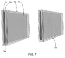
- FIG. 7 is a cutaway view of two probes of the present invention wherein two rectangular plate-shaped probes are depicted.
- FIG. 8 is a cutaway view of two probes of the present invention wherein longer conductive elements are embedded in two rectangular plate-shaped probes.
- the inner core 12 of probe 10 is an inner conducting element preferably made of stainless steel or other electrically-conductive material. This inner conducting element 12 is electrically active and used as a transmission element.
- the inner conducting element 12 is connected to a pulse generator via a coaxial cable (not shown) that is typically used in a TDR system.
- a dielectric layer 14 of the probe 10 is constructed from a hardened epoxy or other dielectric plastic material, and surrounds the inner conducting element 12 .
- Surrounding the dielectric layer 14 is an outer protective shell 16 of the probe 10 . This outer shell 16 is preferably made of stainless steel.
- the probe of the present invention is typically used in pairs 2 a , 2 b in a “balanced” TDR measurement configuration or coaxial arrangements 2 c , 2 d for “unbalanced” TDR measurement configurations.
- Balanced measurements use a small pulse transformer 2 e known as a “balun”, unbalanced measurements do not.
- the probes are inserted into the soil to determine the apparent dielectric constant of the soil or other material being measured by determination of travel times through the material. It is known that the velocity of propagation through a medium is proportional to the square root of the dielectric of the medium. When the probes are inserted in soil, the soil, together with the probes, act as an electronic circuit.
- the transmission speed of a broadband pulse in the probes is affected primarily by the water content of the soil or other material being measured. As water content increases in the soil or other measured material, so also does the travel time of the pulse reaching a reflected end point from the probe beginning. The average travel time from beginning to end as observed in TDR wave form features will determine the apparent dielectric of the material being measured. Thus, there is a relationship between the apparent measured dielectric constant and the moisture content of the measured material. Hence, once the apparent dielectric constant is determined from propagation velocity, the volumetric soil moisture can be computed or deduced.
- One way of deducing soil moisture is to employ a processor that identifies the beginning and end point wave form features from a digitized TDR waveform and from these features determines the average travel time.
- a lookup table is then used to ascertain the moisture content given the average travel time.
- the lookup table is keyed to the type of probes being employed for the measurements as well as the type of material being measured.
- the material associated with a lookup table will exhibit a particular apparent dielectric constant.
- the apparent dielectric constant can be established for a particular material by knowing the propagation velocity of the pulse. Since the propagation velocity is defined by the average travel time and the dimensions of the probe, the travel time is all that is needed to establish the moisture content of the material being measured.
- a moisture value for a measured average travel time can be read directly from the table.
- other techniques to determine soil moisture from the soil dielectric constant may be employed by the present invention.
- a broadband pulse, stepped, impulse, or a combination pulse is transmitted from a pulse generator 20 through a digitizer 24 connected to a microprocessor or other computing device 26 , down coaxial transmission lines or cables 22 , to the probe set 2 a , 2 b , a pair, that can be placed at various distances from one another, or to 2 c , 2 d , a coaxial pair (center probe and ring), the center probe and ring having various diameters. Both pair types are inserted in the material to be measured 24 .
- the signal travels the length of the inner conducting element 12 .
- the pulse energy is broadcast through the dielectric layer 14 of the probes pairs 2 a , 2 b or 2 c , 2 d , and then through the outer shell 16 into the material being measured. Some of the energy is captured in the dielectric layer, increasing the speed of the signal as it is propagated down the inner conducting element. The remainder of the signal is broadcast through the dielectric and outer shell out into the material being measured. Due to an impedance mismatch where the coaxial cable and the probes are joined, a downgoing beginning reference waveform feature in the digitized TDR waveform is produced. The beginning reference waveform feature provides a starting point for measuring the accumulated time delay as the electronic pulse continues to travel through the probe assembly.
- An ending reflection waveform feature in the TDR wave form is created as the electronic pulse reaches the end of the probe assembly producing a large reflection feature as the pulse enters the surrounding soil.
- the apparent dielectric of the soil may be ascertained having determined the accumulated delay time, and in turn one can ascertain the moisture content of the soil using the apparent dielectric value. Once the dielectric properties are known, the moisture content of the material can be determined by utilizing a predetermined lookup table.
- the measured travel time of the pulse using the probe of the present invention is shorter when compared to probes without any dielectric coating.
- a lookup table must be created that properly equates the shortened travel times for this probe to the actual dielectric constants of the materials being measured.
- Such a lookup table can be created by using the probe of the present invention to take measurements of a pulse's travel times and speed of propagation in various materials and then determining the moisture content of these materials that correspond to each dielectric measurement via conventional techniques. Once the table is generated it can be used for subsequent measurements to determine the moisture content that corresponds to each range of subsequently measured travel times.
- the improved probe of the present invention can have different configurations.
- one embodiment of the probe 30 is rod-shaped.
- This rod-shaped probe 30 has a rod-shaped conducting element 32 .
- Surrounding the tubular conducting element 32 is a layer of dielectric material 34 .
- the outer protective shell 36 surrounds the dielectric material 34 and conducting element 32 in a concentric manner.
- the rod-shaped probe 30 of this embodiment can have a cone-shaped pointed tipped (like that shown in FIG. 1) to make it easier to insert it into soil or other material being measured.
- FIG. 4 Another embodiment of the probe of the present invention is shown in FIG. 4 .
- This embodiment entails a disc-shaped probe 40 .
- a pair of these disc shaped probes 40 a and 40 b can be configured to align along a common axis, such that a circular hole 42 a , 42 b through each disc is aligned in parallel and the probes can be mounted on an axle or chassis.
- the inner core of each disc-shaped probe 40 is a conducting element 44 a , made of some conducting material.
- a dielectric material 46 a is sandwiched between the conducting element 44 a and an outer shell 48 a .
- Such a probe configuration can be attached to a tractor or other vehicle. In this manner, the probes can thus be forced into the material to be measured such that readings can be taken while the vehicle is moving.
- Another embodiment of the present invention 50 uses this principle to employ a coil-shaped conductor within a rod-shaped probe.
- a coil-shaped conductor 52 is potted within a dielectric material 54 .
- An outer protective shell 56 surrounds the coil-shaped conductor 52 and the dielectric material 54 .
- the probe is again typically used in pairs 50 a , 50 b .
- the effective length of the conductor is increased over what typically be found in a probe of similar length that employs a straight conductive member.
- a pair of probes 60 a and 60 b is concentrically configured, as shown in FIG. 6 .
- the inner probe 60 a is rod-shaped, having an inner conducting element 62 a that is covered with a dielectric layer 64 a .
- An outer protective shell 66 a encases both the inner conducting element 62 a and the dielectric layer 64 a .
- a ring-shaped probe 60 b surrounds the rod-shaped probe 60 a , with the two probes 60 a , 60 b being concentrically-located but separate.
- the ring-shaped probe 60 b has an inner conducting element 62 b that is surrounded by a dielectric layer 64 b .
- An outer protective shell 66 b encases both the inner conductor 62 b and the dielectric layer 64 b . In use the material to be measured in situated between the two probes 60 a , 60 b such that the material is lodged or flows between the two probes.
- the probe 70 a is plate-shaped.
- the probe 70 a as a plate-shaped inner conductive element 72 a that is surrounded by a dielectric layer 74 a .
- the dielectric layer 74 a is encased in a protective outer shell 76 a .
- two plate-shaped probes 70 a , 70 b can be configured such that they are parallel to each other and the material to be measured flows between the plated-shaped probes, along the larger surfaces of the probes (e.g., 75 a ).
- the probes 70 a , 70 b can also be configured such that they are closer to each other at one end and are further apart at the other end.
- This configuration might typically be used in a mixer or bulk transfer system where material flows between the probes and differing densities of the material to be measured may make it difficult to get accurate readings.
- Angling the probes 70 a , 70 b relative to each other in this manner increases the density of the material to be measured as it is compressed between the probes where the probes are least separated in distance. This increased density of the measured material allows for more accurate and consistent measurements of the dielectric properties of the materials.
- the plate-shaped probes 70 a , 70 b in this embodiment do not necessarily have to be flat. These probes could be curved if desired. Additionally, the plate-shaped probes 70 a , 70 b do not have to be rectangular in shape. For instance, they could be circular, triangular or configured in any type of geometric cross-sectional shape.
- a longer conductor is embedded within a plate-shaped probe 80 a similar to that shown in FIG. 7 .
- the longer conductor 82 a is a snake-like element encased in a dielectric material 84 a .
- the conductor 82 a and dielectric material 84 a are covered by an outer protective shell 86 a .
- these probes 80 a , 80 b can be angled toward each other and can also be of different shapes (e.g., rectangular, circular, triangular, octagonal, etc.)
- the probe of the present invention can be made of various materials.
- the inner conductive element is made of conductive material, typically a metal such as stainless steel or copper, for example.
- the dielectric layer that surrounds the inner conductive element of the probe of the present invention is typically hardenable epoxy of known dielectric constant.
- the outer protective shell is typically made of stainless steel, but could equally well be made of other materials that provide the desired protective effect.
- probes of the present invention using techniques described herein, can also be used in the following measurement areas:
Abstract
Description
Claims (22)
Priority Applications (1)
| Application Number | Priority Date | Filing Date | Title |
|---|---|---|---|
| US09/944,538 US6632534B2 (en) | 2001-08-30 | 2001-08-30 | Encased time domain reflectometry probe |
Applications Claiming Priority (1)
| Application Number | Priority Date | Filing Date | Title |
|---|---|---|---|
| US09/944,538 US6632534B2 (en) | 2001-08-30 | 2001-08-30 | Encased time domain reflectometry probe |
Publications (2)
| Publication Number | Publication Date |
|---|---|
| US20030118832A1 US20030118832A1 (en) | 2003-06-26 |
| US6632534B2 true US6632534B2 (en) | 2003-10-14 |
Family
ID=25481599
Family Applications (1)
| Application Number | Title | Priority Date | Filing Date |
|---|---|---|---|
| US09/944,538 Expired - Lifetime US6632534B2 (en) | 2001-08-30 | 2001-08-30 | Encased time domain reflectometry probe |
Country Status (1)
| Country | Link |
|---|---|
| US (1) | US6632534B2 (en) |
Cited By (9)
| Publication number | Priority date | Publication date | Assignee | Title |
|---|---|---|---|---|
| US20040164758A1 (en) * | 2003-02-21 | 2004-08-26 | Nagar Mohan R. | Substrate impedance measurement |
| US20040251925A1 (en) * | 2003-05-30 | 2004-12-16 | Aritharan Thurairajaratnam | Measurement of package interconnect impedance using tester and supporting tester |
| US20050168230A1 (en) * | 2003-12-18 | 2005-08-04 | Lecroy Corporation | Cap at resistors of electrical test probe |
| US20050274513A1 (en) * | 2004-06-15 | 2005-12-15 | Schultz Roger L | System and method for determining downhole conditions |
| US20060079774A1 (en) * | 2004-10-08 | 2006-04-13 | Wendell Anderson | Microwave biopsy probe |
| US20090212789A1 (en) * | 2008-02-27 | 2009-08-27 | Chih-Ping Lin | Modified tdr method and apparatus for suspended solid concentration measurement |
| US20110006785A1 (en) * | 2008-01-22 | 2011-01-13 | Lubomir Gradinarsky | Analyzing method using a processing structure as a probe |
| US20110057672A1 (en) * | 2009-09-10 | 2011-03-10 | Soilmoisture Equipment Corp. | Coaxial sensor for time-domain reflectometry |
| US8104498B2 (en) | 2004-12-29 | 2012-01-31 | Rain Bird Corporation | Soil moisture sensor and controller |
Families Citing this family (14)
| Publication number | Priority date | Publication date | Assignee | Title |
|---|---|---|---|---|
| US7031856B2 (en) * | 2003-02-05 | 2006-04-18 | Northrop Grumman Corporation | Automatic wire dielectric analyzer |
| US7255002B2 (en) * | 2005-04-07 | 2007-08-14 | Rosemount, Inc. | Tank seal for guided wave radar level measurement |
| US7467548B2 (en) * | 2005-10-14 | 2008-12-23 | Rosemount Tank Radar Ab | Radar level gauge system and coupling |
| GB2481135A (en) * | 2010-06-11 | 2011-12-14 | Utilx Corp | Time domain reflectometry testing of a transmission line in a group of similar lines |
| US9523652B2 (en) * | 2010-10-08 | 2016-12-20 | Poet Research, Inc. | Method and apparatus for measuring moisture content |
| HUE044125T2 (en) * | 2012-09-25 | 2019-09-30 | Grieshaber Vega Kg | Coaxial probe with terminating resistance |
| CN106198650A (en) * | 2016-07-04 | 2016-12-07 | 中国环境科学研究院 | A kind of assay method of debirs material moisture |
| US11221379B2 (en) | 2017-12-21 | 2022-01-11 | Mediatek Singapore Pte. Ltd. | Systems and methods for on-chip time-domain reflectometry |
| US10732215B2 (en) * | 2017-12-21 | 2020-08-04 | Mediatek Singapore Pte. Ltd. | Systems and methods for on-chip time-domain reflectometry |
| CN109307692A (en) * | 2018-04-28 | 2019-02-05 | 中国农业大学 | A kind of soil moisture monitoring system |
| US10648938B2 (en) * | 2018-08-31 | 2020-05-12 | Rohde & Schwarz Gmbh & Co. Kg | Method and system for determining optimum parameters with respect to electromagnetic behavior of a surface |
| US10663410B2 (en) * | 2018-08-31 | 2020-05-26 | Rohde & Schwarz Gmbh & Co. Kg | Method and system for determining a permittivity of a substance layer |
| WO2020230478A1 (en) * | 2019-05-13 | 2020-11-19 | ソニー株式会社 | Measurement device, measurement system, and measurement method |
| CN114440975B (en) * | 2022-01-19 | 2022-08-23 | 武汉新烽光电股份有限公司 | Buried soil temperature and humidity sensor |
Citations (9)
| Publication number | Priority date | Publication date | Assignee | Title |
|---|---|---|---|---|
| US4174498A (en) * | 1978-03-30 | 1979-11-13 | Preikschat F K | Apparatus and method for providing separate conductivity, dielectric coefficient, and moisture measurements of particulate material |
| EP0297604A2 (en) * | 1987-07-03 | 1989-01-04 | Polska Akademia Nauk Instytut Agrofizyki | Reflectometric moisture meter for capillary-porous materials, especially for the soil |
| GB2213596A (en) * | 1988-01-07 | 1989-08-16 | Protimeter Plc | Disposable humidity sensor |
| US5136249A (en) * | 1988-06-20 | 1992-08-04 | Commonwealth Scientific & Industrial Research Organization | Probes for measurement of moisture content, solids contents, and electrical conductivity |
| EP0585691A1 (en) * | 1992-08-18 | 1994-03-09 | Nirsystems Incorporated | An improved system for measuring the moisture content of powder and fiber optic probe therefor |
| US5420517A (en) * | 1992-03-23 | 1995-05-30 | Soilmoisture Equipment Corp. | Probe for measuring moisture in soil and other mediums |
| US5554936A (en) * | 1994-12-01 | 1996-09-10 | Mohr; Charles L. | Mixed fluid time domain reflectometry sensors |
| WO1997009590A2 (en) * | 1995-08-30 | 1997-03-13 | Purdue Research Foundation | Soil moisture or dielectric constant measuring system |
| WO1998025109A2 (en) * | 1996-11-22 | 1998-06-11 | Berwind Corporation | Material level sensing |
-
2001
- 2001-08-30 US US09/944,538 patent/US6632534B2/en not_active Expired - Lifetime
Patent Citations (11)
| Publication number | Priority date | Publication date | Assignee | Title |
|---|---|---|---|---|
| US4174498A (en) * | 1978-03-30 | 1979-11-13 | Preikschat F K | Apparatus and method for providing separate conductivity, dielectric coefficient, and moisture measurements of particulate material |
| EP0297604A2 (en) * | 1987-07-03 | 1989-01-04 | Polska Akademia Nauk Instytut Agrofizyki | Reflectometric moisture meter for capillary-porous materials, especially for the soil |
| GB2213596A (en) * | 1988-01-07 | 1989-08-16 | Protimeter Plc | Disposable humidity sensor |
| US5136249A (en) * | 1988-06-20 | 1992-08-04 | Commonwealth Scientific & Industrial Research Organization | Probes for measurement of moisture content, solids contents, and electrical conductivity |
| US5420517A (en) * | 1992-03-23 | 1995-05-30 | Soilmoisture Equipment Corp. | Probe for measuring moisture in soil and other mediums |
| US5646537A (en) * | 1992-03-23 | 1997-07-08 | Soilmoisture Equipment Corp. | Antenna-probe measuring moisture in soil and other mediums |
| EP0585691A1 (en) * | 1992-08-18 | 1994-03-09 | Nirsystems Incorporated | An improved system for measuring the moisture content of powder and fiber optic probe therefor |
| US5554936A (en) * | 1994-12-01 | 1996-09-10 | Mohr; Charles L. | Mixed fluid time domain reflectometry sensors |
| US5723979A (en) * | 1994-12-01 | 1998-03-03 | Mohr; Charles L. | Mixed fluid time domain reflectometry sensors |
| WO1997009590A2 (en) * | 1995-08-30 | 1997-03-13 | Purdue Research Foundation | Soil moisture or dielectric constant measuring system |
| WO1998025109A2 (en) * | 1996-11-22 | 1998-06-11 | Berwind Corporation | Material level sensing |
Cited By (15)
| Publication number | Priority date | Publication date | Assignee | Title |
|---|---|---|---|---|
| US20040164758A1 (en) * | 2003-02-21 | 2004-08-26 | Nagar Mohan R. | Substrate impedance measurement |
| US6891392B2 (en) * | 2003-02-21 | 2005-05-10 | Lsi Logic Corporation | Substrate impedance measurement |
| US20040251925A1 (en) * | 2003-05-30 | 2004-12-16 | Aritharan Thurairajaratnam | Measurement of package interconnect impedance using tester and supporting tester |
| US7525328B2 (en) | 2003-12-18 | 2009-04-28 | Lecroy Corporation | Cap at resistors of electrical test probe |
| US7295020B2 (en) * | 2003-12-18 | 2007-11-13 | Lecroy Corporation | Cap at resistors of electrical test probe |
| US20070273360A1 (en) * | 2003-12-18 | 2007-11-29 | Lecroy Corporation | Cap at resistors of electrical test probe |
| US20050168230A1 (en) * | 2003-12-18 | 2005-08-04 | Lecroy Corporation | Cap at resistors of electrical test probe |
| US20050274513A1 (en) * | 2004-06-15 | 2005-12-15 | Schultz Roger L | System and method for determining downhole conditions |
| US7228900B2 (en) | 2004-06-15 | 2007-06-12 | Halliburton Energy Services, Inc. | System and method for determining downhole conditions |
| US20060079774A1 (en) * | 2004-10-08 | 2006-04-13 | Wendell Anderson | Microwave biopsy probe |
| US8104498B2 (en) | 2004-12-29 | 2012-01-31 | Rain Bird Corporation | Soil moisture sensor and controller |
| US8671969B2 (en) | 2004-12-29 | 2014-03-18 | Rain Bird Corporation | Soil moisture sensor and controller |
| US20110006785A1 (en) * | 2008-01-22 | 2011-01-13 | Lubomir Gradinarsky | Analyzing method using a processing structure as a probe |
| US20090212789A1 (en) * | 2008-02-27 | 2009-08-27 | Chih-Ping Lin | Modified tdr method and apparatus for suspended solid concentration measurement |
| US20110057672A1 (en) * | 2009-09-10 | 2011-03-10 | Soilmoisture Equipment Corp. | Coaxial sensor for time-domain reflectometry |
Also Published As
| Publication number | Publication date |
|---|---|
| US20030118832A1 (en) | 2003-06-26 |
Similar Documents
| Publication | Publication Date | Title |
|---|---|---|
| US6632534B2 (en) | Encased time domain reflectometry probe | |
| US5646537A (en) | Antenna-probe measuring moisture in soil and other mediums | |
| Topp et al. | Soil water content | |
| Dalton | Development of time‐domain reflectometry for measuring soil water content and bulk soil electrical conductivity | |
| Nyfors | Industrial microwave sensors—A review | |
| Leib et al. | Field evaluation and performance comparison of soil moisture sensors | |
| Robinson et al. | A review of advances in dielectric and electrical conductivity measurement in soils using time domain reflectometry | |
| Cassel et al. | Practical considerations for using a TDR cable tester | |
| EP0462803B1 (en) | Method and apparatus for determining oil/water mixtures in a well borehole | |
| US4503384A (en) | Microwave probe for measurement of dielectric constants | |
| US20090212789A1 (en) | Modified tdr method and apparatus for suspended solid concentration measurement | |
| US5442293A (en) | Method and apparatus for determining fluid content and conductivity in porous materials | |
| US4544880A (en) | Microwave probe for measurement of dielectric constants | |
| Smith et al. | A scale model for studying ground penetrating radars | |
| EP0741291B1 (en) | A measurement device | |
| US4543823A (en) | Microwave probe for detecting oil level | |
| US8461851B2 (en) | Systems for transverse electromagnetic mode in-situ soil testing | |
| JP4194179B2 (en) | Characteristic measuring device | |
| CN108562623A (en) | A kind of sensor and preparation method thereof being suitable for frequency-domain frequency stepping physiometry Dielectric Constant of NaCl Soil characteristic | |
| CN109520405A (en) | A kind of sensor measuring ice layer thickness | |
| Reeves et al. | Time domain reflectometry for measuring soil water content in range surveys. | |
| Delaney et al. | Dielectric measurements of frozen silt using time domain reflectometry | |
| Dalton et al. | Soil water content and salinity assessment for irrigation scheduling using time-domain reflectometry: Principles and applications | |
| Topp et al. | Evaluation of shaft-mounted TDT readings in disturbed and undisturbed media | |
| Whalley | Development and evaluation of a microwave soil moisturesensor for incorporation in a narrow cultivator tine |
Legal Events
| Date | Code | Title | Description |
|---|---|---|---|
| AS | Assignment |
Owner name: SOILMOISTURE EQUIPMENT CORP., CALIFORNIA Free format text: ASSIGNMENT OF ASSIGNORS INTEREST;ASSIGNORS:SKALING, WHITNEY;RUDOLICS, LASLO;REEL/FRAME:012170/0968 Effective date: 20010830 |
|
| STCF | Information on status: patent grant |
Free format text: PATENTED CASE |
|
| FPAY | Fee payment |
Year of fee payment: 4 |
|
| FPAY | Fee payment |
Year of fee payment: 8 |
|
| FPAY | Fee payment |
Year of fee payment: 12 |
|
| AS | Assignment |
Owner name: B & W SKALING INVESTMENTS, LLC, CALIFORNIA Free format text: ASSIGNMENT OF ASSIGNORS INTEREST;ASSIGNOR:SOILMOISTURE EQUIPMENT CORP.;REEL/FRAME:055800/0796 Effective date: 20210331 |
|
| AS | Assignment |
Owner name: SOILMOISTURE EQUIPMENT CORP., CALIFORNIA Free format text: ASSIGNMENT OF ASSIGNORS INTEREST;ASSIGNOR:B&W SKALING INVESTMENTS, LLC;REEL/FRAME:062692/0658 Effective date: 20221003 |