US6631302B1 - System and method for aligning components of optical head - Google Patents
System and method for aligning components of optical head Download PDFInfo
- Publication number
- US6631302B1 US6631302B1 US09/544,370 US54437000A US6631302B1 US 6631302 B1 US6631302 B1 US 6631302B1 US 54437000 A US54437000 A US 54437000A US 6631302 B1 US6631302 B1 US 6631302B1
- Authority
- US
- United States
- Prior art keywords
- translation stage
- component
- stage
- holding
- microscope
- Prior art date
- Legal status (The legal status is an assumption and is not a legal conclusion. Google has not performed a legal analysis and makes no representation as to the accuracy of the status listed.)
- Expired - Fee Related
Links
Images


Classifications
-
- G—PHYSICS
- G11—INFORMATION STORAGE
- G11B—INFORMATION STORAGE BASED ON RELATIVE MOVEMENT BETWEEN RECORD CARRIER AND TRANSDUCER
- G11B7/00—Recording or reproducing by optical means, e.g. recording using a thermal beam of optical radiation by modifying optical properties or the physical structure, reproducing using an optical beam at lower power by sensing optical properties; Record carriers therefor
- G11B7/12—Heads, e.g. forming of the optical beam spot or modulation of the optical beam
- G11B7/22—Apparatus or processes for the manufacture of optical heads, e.g. assembly
Definitions
- This invention relates to optical heads used to write data to and read data from an optical disk, and in particular to a system and method for aligning the components of a miniature optical head for use in a personal electronic device such as a audio player or digital camera.
- the increasing miniaturization of computers and personal electronic devices (PEDs) has led to a need for extremely small components.
- the above-referenced application Ser. No. 09/457,104 describes a low profile optical head, used in optical disk storage devices, that can have a height (measured perpendicular to the optical disk) of, for example, 3.25 mm.
- a feature of the head is that its components are rigidly attached to each other with a permanent adhesive and cannot be adjusted after the head has been assembled. This distinguishes this head from the larger optical heads used in, for example, conventional compact disk (CD) players, where the light source or lens can be adjusted after assembly to ensure that the read-write beam is properly aligned with respect to the objective lens and photodetector.
- CD compact disk
- a system for aligning the components of an optical head comprises a rotational stage; a first mechanical path extending from a first side of the rotational stage, the first mechanical path comprising a first X-translation stage and a first Y-translation stage; a first holding mechanism attached to an end of the first mechanical path for holding a first component of the optical head; a second mechanical path extending from a second side of the rotational stage, the second mechanical path comprising a second X-translation stage and a second Y-translation stage; a second holding mechanism attached to an end of the second mechanical path for holding a second component of the optical head; and a Z-translation stage positioned so as to alter the spacing between the first and second holding mechanisms in a Z direction.
- the system also comprises a first microscope for viewing the first and second components of the optical head in a Z direction and a second microscope for viewing the first and second components of the optical head in a direction perpendicular to the Z
- the first mechanical path comprises a stack comprising the first X-translation stage and the first Y-translation stage, the stack being mounted on the rotational stage.
- the first holding mechanism is mounted on the first Y-translation stage.
- the rotational stage is mounted on the second Y-translation stage, and the second Y-translation stage is mounted on a base member.
- the second X-translation stage is also mounted on the base member, and the Z-translation stage is mounted on the second X-translation stage.
- the second holding mechanism is mounted on the Z-translation stage.
- the system comprises a tracking actuator for holding a piece of optical media, an analog circuit for electrical connection to a component of an optical head held by one of the first and second holding mechanisms, and an oscilloscope electrically connected to the analog circuit.
- the tracking actuator is driven by a low-frequency oscillator and vibrates the piece of optical media in a direction parallel to the surface thereof and perpendicular to the data tracks on the surface thereof.
- the system can also comprise a focus actuator which is likewise driven by a low-frequency signal and vibrates the piece of media in a direction perpendicular to the surface thereof.
- This invention also includes a system for aligning the components of an optical head comprising a first holding device; a second holding device; a mechanical path extending between the first and second holding devices, the mechanical path comprising: a rotational stage; a first X-translation stage and a first Y-translation stage; a second X-translation stage and a second Y-translation stage; and a Z-translation stage positioned so as to alter the spacing between the first and second holding mechanisms in a Z direction.
- This invention also includes a method of assembling the components of an optical head.
- the method comprises positioning first and second components of the optical head adjacent to each other; connecting the first component to a source of electrical power to energize a light source within the first component and thereby produce a light beam, the light beam following a forward path out of the first component and into, through and out of the second component; translating the first component in X and Y directions until the light beam emerging from the first component on a first section of the forward path coincides with a predetermined Z-axis; translating the second component in the X and Y directions until the light beam emerges from the second component on a second section of the forward path at a predetermined location on the second component; reflecting the light beam along a return path into, through and out of the second component; and rotating the first component about the Z-axis until the light beam in the return path strikes the first component at a predetermined location.
- the method also includes bonding the first and second components. The bonding can be performed by applying a UV adhesive and exposing the UV
- this invention includes a gripper for holding a component of an optical head.
- the gripper comprises a first jaw and a second jaw connected together at a pivot point, the first jaw comprising a first straight edge, and second jaw comprising second and third straight edges, the straight edges between positioned on the jaws such that the first straight edge is located between the second and third straight edges when the jaws are closed.
- FIG. 1 is a conceptual block diagram of an alignment system in accordance with this invention.
- FIG. 2A is a top view of the cradle.
- FIG. 2B is a side view of the cradle.
- FIG. 3A is a block diagram of the analog signal processing circuit.
- FIGS. 3B and 3C show top views of the photodetector array in the optical head.
- FIG. 3D is a schematic diagram of the detector pre-amplifiers and the detector algebra unit.
- FIG. 4 is a side view of a low-profile optical head that can be aligned using the system and method of this invention.
- FIG. 5 is a top view of the optical head.
- FIG. 6 is a perspective view of the optical head.
- FIG. 7 is an exploded view of the periscope-lens assembly of the optical head.
- FIG. 8 is an exploded view showing the periscope-lens assembly and the optical pickup unit (OPU) assembly of the head.
- FIG. 9A illustrates the placement of the vacuum-tipped holding device on the upper Y-translation stage.
- FIG. 9B is a close-up view of the the vacuum-tipped holding device.
- FIG. 9C illustrates the polishing of the end of the vacuum-tipped holding device.
- FIGS. 10A-10D are detailed views of the gripper useful in holding a component of the optical head during assembly.
- FIGS. 11A and 11B are top and side views, respectively, of the quarter-wave plate orientation jig.
- FIG. 11C is a side view showing the placement of the quarter-wave plate on the periscope.
- FIGS. 12A-12H are views of the lens-spacer alignment tool.
- FIGS. 13A-13I illustrate the use of a knife-edge plate to generate an intensity profile of the laser spot.
- FIGS. 14A and 14B illustrate several additional embodiments according to the invention.
- FIG. 15 is a side view of the media actuator mounted on the cradle.
- FIG. 16 is a block diagram of the drive circuitry for the media actuator.
- Alignment system 10 includes a gripper 102 which functions as a holding mechanism for one component of the optical head and a cradle 104 which functions as a holding mechanism for a second component of the optical head.
- the two components to be aligned are not shown in FIG. 1 .
- Gripper 102 which is described in greater detail below, is mounted via a gripper base 106 on a stack 105 that includes a Y-translation stage 108 and an X-translation stage 110 .
- Translation stages 108 and 110 are well known in the mechanical arts and are preferably constructed as steel stages with crossed roller bearings on the critical axes.
- Stack 105 is mounted on a rotational (theta) stage 112 , which in turn is mounted on a Y-translation stage 114 .
- Y-translation stage 114 is mounted on a platform 116 of a measurement microscope 118 .
- Cradle 104 is mounted on a Z-translation stage 119 , which is mounted on an X-translation stage 120 .
- X-translation stage 120 is mounted on the platform 116 along with Y-translation stage 114 .
- Cradle 104 is shown in FIG. 2A, which is a top view, and FIG. 2B, which is a side view.
- Cradle 104 includes a mounting base 1044 in which are formed vacuum holes 1040 and 1041 .
- Holes 1040 and 1041 are in flow communication with a vacuum plenum 1042 within base 1044 and a port 1050 which is connected to a source of vacuum.
- an object herein a component of an optical head
- Holes 1045 and 1046 are for mounting cradle 104 to Z-translation stage 119 with mounting screws.
- Flat 1047 , countersink 1048 and V-groove 1049 serve as kinematic mounting points for the quarter-wave plate orientation fixture and the media actuator, as described below.
- FIGS. 10A-10D are detailed views of gripper 102 .
- Gripper 102 includes jaws 802 and 804 that are connected together at a pivot point 806 .
- Jaw 804 is rigidly fixed to gripper base 106 with two screws, and jaw 802 rotates with respect to jaw 804 about pivot point 806 .
- Jaws 802 and 804 are biased towards a closed position by a spring 808 which can provide a closing force of 50 grams, for example.
- Jaw 802 comprises a first straight edge 810 (in a dimension perpendicular to the paper), and jaw 804 comprises a second straight edge 812 and a third straight edge 814 .
- Straight edges 810 , 812 and 814 are positioned such that straight edge 810 is located between straight edges 812 , 814 when jaws 802 and 804 are closed position.
- Jaw 802 comprises a ridge 816 having a first planar side 818 and a second planar side 820 , the first and second sides 818 , 820 between oriented with respect to each other at an angle a.
- Straight edge 810 is located at a junction of the first and second sides 818 , 820 .
- Jaw 804 comprises a V-shaped cavity 822 , the straight edges 812 , 814 being located on opposite sides of the V-shaped cavity 822 .
- the ridge 816 and cavity 822 are formed in complementary shapes such that ridge 816 mates with cavity 822 when the jaws are closed.
- Gripper 102 (and gripper base 106 ) can be removed from Y-translation stage 108 , as necessary, to allow other devices to be attached to the Y-stage.
- FIGS. 10C and 10D show how a rectangular object, such as a prism, or a cylindrical object, such as a lens, can readily be held in gripper 102 .
- each of stages 108 , 110 and 119 is equipped with a differential micrometer (not shown) to allow precision adjustment of the components mounted in gripper 102 and on cradle 104 with respect to each other.
- the translation and rotational stages and micrometers are available from Newport Corp. of Irvine, Calif.
- gripper 102 can be rotated by rotation stage 112 and can be translated in the X direction by stage 110 and in the Y-direction by stages 102 and 114 .
- Cradle 104 can be translated in the Z direction by stage 119 and in the X direction by stage 120 . While the Z direction is shown as being vertical and the X and Y directions are shown as being horizontal in FIG. 1, it should be understood that this need not be the case in all embodiments.
- the X, Y and Z directions refer to any three mutually perpendicular axes, however oriented.
- Platform 116 is a part of measurement microscope 118 .
- microscope 118 is a Nikon model MM- 40 -L 3 measurement microscope.
- Microscope 118 includes a head unit 122 , which contains a magnification lens system and a video camera 124 and allows the optical head components to be viewed in the Z direction.
- Platform 116 can be adjusted in the X and Y directions and head unit 122 can be adjusted in the Z direction.
- the view downward through head unit 122 includes a pair of perpendicular cross-hairs which can be rotated.
- System 10 also includes a side view video microscope 126 , which is mounted to the cradle 104 (for clarity, microscope 126 is shown as being separate in FIG. 1 ).
- Microscope 126 allows a view of the optical head components in a plane perpendicular to the Z direction. This allows the operator to bring the components together in the Z direction without risk of “crashing” them during assembly.
- microscope 126 has a fixed magnification of approximately 25 (from object to the monitor screen of computer 136 ). Because microscope 126 is mounted to cradle 104 , the cradle 104 appears at a fixed position in microscope 126 .
- video microscope 126 contains aboard camera CCD model VM1030A, available from Circuit Specialists of Mesa, Ariz., and a 40 mm f/3.2 camera lens available from Universe Kogaku (America) of Oyster Bay, N.Y.
- alignment system 10 includes a source of ultraviolet (UV) light 138 , which is positioned with respect to gripper 102 and cradle 104 such that a beam of UV light from source 138 can be used to cure a UV adhesive and thereby bond components held by the gripper 102 and cradle 104 .
- UV light source 138 can be a high-intensity device which allows a curing time of 20 seconds or less and can have dual light pipes which allow two locations to be cured simultaneously. UV light source 138 is typically positioned 1 ⁇ 4 inch to 1 inch from the components to be bonded. UV light source can be the Green Spot model, available from UV Source, Inc., of Torrance, Calif.
- Microscopes 118 and 126 provide video signals on lines 128 which are used to generate a side view (illustrated in box 130 ) and a top view (illustrated in box 132 ) of gripper 102 , cradle 104 and the components to be assembled.
- the side and top views are observed by passing the video signals on lines 128 to closed-circuit video monitors.
- Video signals are passed to a frame grabber 134 to allow computer analysis of the images.
- Cameras 134 A and 134 B are connected to frame grabber 134 .
- FIG. 3A shows a block diagram of the analog signal processing circuit.
- Laser driver 141 which is connected to the laser diode 202 in optical pick-up unit 20 , is available from Elantec Corp. of Milpitas, California (model EL 6259 C).
- Data acquisition system 140 is available from National Instruments of Austin, Texas (model PCI-Mio-16E-1).
- Frame grabber 134 can be purchased from ImageNation of Beaverton, Oregon (model PX 610 A).
- Oscilloscope 142 can be the Infinium model, available from Hewlett Packard.
- FIGS. 3B and 3C show top views of photodetector array 232 , FIG. 3B being at a magnification of about 100X and FIG. 3C being at a magnification of about 200X.
- photodetector array 232 contains five sections A-E and is mounted at an angle ⁇ with respect to the longitudinal axis of sub-mount 206 because in this embodiment optical head 20 is mounted on a rotary actuator which pivots about a point as head 20 sweeps across a disk.
- Photodetector array 232 can measure 0.3 mm ⁇ 0.32 mm; the width of section E can be 0.05 mm; and the spacing between the sections can be 0.005 mm.
- the angle ⁇ is set such that the track is parallel to the length of section E when the head 20 is positioned at a midpoint between the inner and outer diameters of the data regions of the disk. In effect, the angle ⁇ minimizes the error that occurs because of the change in the direction of the data tracks as head 20 moves to different positions on the disk. In one embodiment, angle ⁇ is 6.745°.
- Each of sections A-E is a photodiode formed in silicon sub-mount 206 in a well known manner and is connected by a conductive trace to a corresponding pad in a connector 237 in silicon sub-mount 206 .
- FIG. 3D is a schematic diagram of detector pre-amp unit 144 and detector algebra unit 146 .
- Sections A-E of photodetector 232 are represent by photodiodes A-E.
- Each of the photodiodes A-E is connected to one of transimpedance amplifiers 1441 - 1445 within pre-amp unit 144 .
- the output terminals of the transimpedance amplifiers are connected to summing amplifiers 1461 - 1464 and difference amplifiers 1465 and 1466 in detector algebra unit 146 to produce three output signals: a focus error signal (FES), a tracking error signal (TES) and signal that is the sum of the outputs of photodiodes A-E (SUM).
- FES, TES and SUM are delivered to oscilloscope 142 .
- Detector pre-amps 144 and detector algebra unit 146 can be constructed from operational amplifiers available from Texas Instruments (model TL 084).
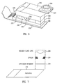
- FIGS. 4, 5 , and 6 are side, top and perspective views, respectively, of a low-profile optical head or optical pick-up unit (OPU) 20 that can be assembled using alignment system 10 .
- the light source in optical head 20 is an edge-emitting laser diode 202 that is mounted on a laser mount 204 .
- Laser mount 204 in turn is mounted on a sub-mount 206 which can be a die cut from a silicon wafer.
- Above laser diode 202 is an optical die 208 , which can include lenses, gratings, holograms and other optical components or devices.
- spacer blocks 210 and 212 Interposed between sub-mount 206 and optical die 208 are spacer blocks 210 and 212 , one side of spacer block 210 being provided with a 45° turning mirror 214 that reflects the horizontal laser beam produced by laser diode 202 to a vertical upward direction.
- a prism or periscope 216 Mounted atop optical die 208 is a prism or periscope 216 , that can be made of a number of materials, including fused silica or flint glass (SF 2 ), and that is transparent to the laser beam emitted by laser diode 202 .
- the ends of periscope 216 are angled at about 45° to the horizontal and are coated with a substantially reflective coating such as aluminum or silver to form turning mirrors 218 and 220 .
- Periscope 216 also includes an internal polarization beam splitter surface 222 , also angled at about 45° with respect to the horizontal, which is substantially reflective (i.e., acts as a mirror) for light of a first polarization and substantially transmissive for light of a second polarization.
- periscope 216 Mounted on top of periscope 216 are a quarter-wave plate 224 , a lens spacer 226 and an objective lens 228 . Also shown in FIG. 4 is a section of an optical media 230 , which is positioned a preselected distance (e.g., 0.3 mm) from objective lens 228 .
- a preselected distance e.g., 0.3 mm
- the laser beam emitted by laser diode 202 follows a forward path to optical media 230 , where it is reflected along a return path to a photodetector array 232 in the sub-mount 206 .
- the forward path includes a first section 234 between turning mirror 214 and beam splitter surface 222 , a second section 236 between beam splitter surface 222 and turning mirror 220 , and a third section 238 between turning mirror 220 and optical media 230 .
- the return path includes a first section 240 between optical media 230 and turning mirror 220 , a second section 242 between turning mirror 220 through beam splitter surface 222 to turning mirror 218 , and a third section 244 between turning mirror 218 and photodetector array 232 .
- the polarization of the beam emitted by laser diode 202 is such that the beam is reflected by beam splitter surface 222 on its forward path; as the beam passes through quarter-wave plate 224 in the forward and return directions, the polarization of the beam is changed such that the beam passes through beam splitter surface 222 on its return path.
- Optical head 20 is powered through wire bonds 235 located at one end of sub-mount 206 .
- sub-mount 206 is mounted with epoxy or another adhesive in a recess formed in the surface of a flex circuit 236 , which can be, for example, a Kapton copper flex circuit.
- Wire bonds 235 are formed between pads in connector 237 and pads on the flexible circuit 236 .
- the data signals generated in optical head 20 are also carried by the flex circuit 236 .
- Optical head 20 is typically of an extremely small size.
- the height H of head 20 can be only 3.25 mm.
- optical head 20 Many additional details concerning optical head 20 are described in the above-referenced application Ser. No. 09/457,104.
- optical head 20 For optical head 20 to function properly, it is essential that the laser beam pass through the central axis 239 of lens 228 (see FIG. 4 ). Otherwise, the beam will not be properly focused on the optical media 230 . In addition, the beam must fall at precisely the correct location on photodetector array 232 . There are numerous manufacturing tolerances and other sources of error that can affect these two requirements, for example: the angle at which the laser beam emerges from laser source 202 , the positioning of laser source 202 on laser mount 204 , the angles of turning mirrors 214 , 218 and 220 and of beam splitter surface 222 , and the locations of lens 228 with respect to periscope 216 and of photodetector 232 in sub-mount 206 . In conventional optical heads, certain of the components, such as the laser source and mirrors, can be adjusted after assembly to achieve the correct alignment. In optical head 20 , however, because of its miniature size, all elements are permanently bonded together during assembly and later adjustment is impossible.
- optical head 20 can be assembled in several stages.
- spacer 226 is initially attached to lens 228 .
- Quarter-wave plate 224 is then attached to periscope 216 , and the lens-spacer assembly is attached to quarter-wave plate 224 .
- periscope-lens assembly 60 must be attached to OPU assembly 62 . As described above, this must be accomplished in such a way that the laser beam is correctly aligned with both lens 228 and photodetector array 232 .
- microscope 118 and the translation and rotational stages must be properly set up.
- the movement axes of X-translation stages 110 and 120 and Y-translation stages 108 and 114 and the surface of cradle 104 must be made parallel to the platform 116 of microscope 118 . This is done using a granite surface plate and a dial indicator.
- the movement of microscope head 122 and Z-translation stage 119 must be made perpendicular to platform 116 .
- Spacer 226 is attached to lens 228 using the spacer-lens bonding fixture 100 , shown in FIGS. 12A-12H.
- a groove 1004 is formed in the top surface of a metal block 1002 , which could be a cube of black anodized aluminum measuring 11 ⁇ 2′′ ⁇ 11 ⁇ 2′′ ⁇ 11 ⁇ 2′′, for example.
- Side plates 1006 and 1008 are attached to the sides of block 1002 with screws, as shown in FIGS. 12A and 12B.
- Side plate 1006 has a hole 1007 bored through it, into which a spring-loaded plunger 1016 is fixed.
- Side plate 1008 has a hole 1009 bored in it, into which a gage pin 1010 is inserted and attached with a set screw 1012 . As shown in FIG.
- a stack of lenses 228 and lens spacers 226 is placed in groove 1004 , with the lenses 228 alternating with the spacers 226 .
- Groove 1004 has planar sides that are angled at 90° with respect to each other. As shown in FIG. 12E, a trough 1005 is cut at the bottom of groove 1004 to accommodate square lenses if necessary.
- the depth of the groove (D 1 ) is 0.035′′
- the width of the trough 1005 (D 2 ) is 0.010′′
- the diameter of gage pin 1010 is 0.051′′.
- the geometry of groove 1004 is adjusted such that the distance (D 3 ) that gage pine 1010 protrudes above the surface of block 1002 is 0.035′′ ⁇ 0.005′′.
- a spring plate 1014 is attached with screws to the surface of block 1002 on one side of groove 1004 . When so attached, spring plate 1014 ensures that the lenses 228 and spacers 226 are securely seated in groove 1004 .
- a small dot of a UV adhesive such as NOA 63 adhesive, available from Norland Optical Adhesive, is applied to the interface between each lens-spacer pair. Within 10 seconds of application, the stack is exposed to UV light. Spring plate 1014 and spring-loaded plunger 1016 are released, and the lens-spacer pairs are rotated 180° with a tweezers. A dot of UV adhesive is applied to the other side of each lens-spacer pair and the stack is again exposed to UV light. Finally, spring plate 1014 and spring-loaded plunger 1016 are released, and lenses 228 and spacers 226 are removed from fixture 100 .
- NOA 63 adhesive available from Norland Optical Adhesive
- the groove 1004 can also accommodate square lenses, in which case the perpendicular edges of the spacers contact the sides of the groove. Also, dummy spacers may be placed between the lens-spacer pairs that are to be bonded. Two spring plates 1014 may be used, as shown in FIG. 12 H. One dot of the UV adhesive is applied at the apex 1015 , one of spring plates 1014 is removed, and another dot of the adhesive is applied on the exposed side of the lens-spacer pair.
- Vacuum-tipped holding device 70 includes a tube 704 that is attached to a holding fixture 707 and a mounting bracket 708 .
- Mounting bracket 708 can be mounted on Y-translation stage 108 , as shown in FIG. 9 A.
- Tube 704 can be made of stainless steel adhesive dispensing tip available from EFD, Inc. of East Buffalo, R.I. (part number 5120-B-90).
- the end 702 of tube 704 needs to be extremely flat, smooth and parallel to cradle 104 to enable adequate grip and proper positioning of optical components.
- the honing process starts with a coarse stone and ends with an ultra-fine stone; 3 or 4 stones of progressively finer grit can be used.
- grinding stone 706 is moved manually back and forth between cradle 104 and tube 704 (preferably in a FIG. 8 pattern), thereby polishing the end 702 and also the top surface of cradle 104 .
- the polished end 702 has an extremely flat annular surface that, when a vacuum is applied to the interior of tube 704 , holds quarter-wave plate 224 (or any other object having a flat surface) in a very precise, repeatable position.
- Tube 704 can have an inner diameter of 0.60 mm and an outer diameter of 0.91 mm, which is suitable for holding a quarter-wave plate 224 measuring 1.3 ⁇ 1.3 ⁇ 0.040 mm.
- periscope 216 is placed on cradle 104 but no vacuum is applied. Periscope 216 is viewed under the microscope and, if dirty, is removed and cleaned with acetone and a cotton swab. Periscope 216 is gripped with gripper 102 and cradle 104 is lowered 25 microns. Using stage 112 , periscope 216 is rotated until its edge is parallel to the movement of microscope 118 in the X-direction within 3 microns over the length of the periscope. To do this, platform 116 is moved back and forth in the X-direction and stage 112 is rotated until the edge of periscope 216 remains centered in the cross-hairs in the view through microscope 118 .
- periscope 216 is measured.
- Periscope 216 is placed in gripper 102 .
- the vacuum in cradle 104 is released, and cradle 104 is lowered 25 microns.
- Periscope 216 is moved out of the field of view of microscope 118 .
- Microscope 118 is focused on cradle 104 .
- the cross-hairs in microscope 118 are centered on the right edge of vacuum hole 1041 in cradle 104 .
- the X readout of microscope 118 is zeroed at this point.
- gripper 102 periscope 216 is moved into position over the vacuum holes in cradle 104 .
- Microscope 118 is refocused until the surface of cradle 104 is visible through quarter-wave plate 224 .
- the X-stage of microscope 118 (platform 116 ) is then moved until the right edge of vacuum hole 1041 is aligned with the cross-hairs of microscope 118 .
- the displacement of microscope 118 in the X-direction is recorded. This is the offset of periscope 216 , i.e., the distance between axes 246 and 239 shown in FIG. 4 .
- Cradle 104 is lifted 25 microns and periscope 216 is vacuum-clamped to cradle 104 .
- Periscope 216 is released from gripper 102 , and gripper 102 is removed and replaced by vacuum-tipped holding device 70 .
- the quarter-wave plates are prepared by placing several of them on a clean microscope slide and separating those with the anti-reflective (AR) coating facing upward from those with the AR coating facing downward.
- the plates with the AR coating facing upward appear to have orange edge chips when viewed under a microscope using a 110X objective lens.
- the polarization directions of quarter-wave plate 224 can be oriented properly before placement on periscope 216 using the orientation jig 90 shown in FIGS. 11A and 11B.
- Jig 90 is a known type of device.
- a quarter-wave plate 224 with its AR coating facing upward is placed on the center of a rotatable mirror 902 .
- a laser source 904 directs a laser beam 906 downward through polarization beam splitter 908 .
- Laser beam 906 passes through quarter-wave plate 224 and is reflected from mirror 902 . Since the polarization of beam 906 is changed by passing twice through quarter-wave plate 224 , on its return path beam 906 is reflected from polarization beam splitter 908 to an optical power meter 910 .
- Jig 90 has three kinematic mounting points 912 (e.g., balls) that mate with kinematic mounting points (e.g., a countersink, a groove and a flat) in a kinematic base member 914 , to ensure that jig 90 is positioned at a precise, repeatable position with respect to base member 914 .
- Kinematic mounting points 912 also mate with kinematic mounting points 1047 , 1048 , 1049 in cradle 104 .
- jig 90 is removed from base 914 and placed on cradle 104 , with kinematic mounting points 912 in base 914 in mating contact with kinematic mounting points 1047 , 1048 , 1049 in cradle 104 . Because of the placement of kinematic mounting points 1047 , 1048 , 1049 (see FIG. 2 A), there is adequate room on cradle 104 for both jig 90 and periscope 216 .
- Vacuum-tipped holding device 70 shown in FIG. 9A, is mounted onto Y-translation stage 108 .
- Y-translation stage 108 and X-translation stage 110 the end of tube 704 is brought into contact with the surface of quarter-wave plate 224 , and a vacuum is applied to tube 704 .
- Quarter-wave plate 224 is lifted from mirror 902 .
- quarter-wave plate 224 is moved to its approximate position with respect to periscope 216 , 25 microns above the top surface of periscope 216 .
- periscope 216 is lifted and quarter-wave plate 224 is adjusted laterally until quarter-wave plate 224 is centered with respect to periscope 216 in the Y-direction and the edge of quarter-wave plate 224 is located 0.15 mm to the left of the junction between turning mirror 220 and the lower surface of periscope 216 , as shown in FIG. 11 C.
- This alignment is performed by using microscope 118 to focus on the lower surface of periscope 216 .
- a small dot of a UV adhesive is placed at a comer where quarter-wave plate 224 meets periscope 216 .
- NOA 61 adhesive from Norland Optical Adhesive can be used.
- Z-translation stage 119 is adjusted manually until a “rainbow” (i.e., white light fringes) appears between quarter-wave plate 224 and periscope 216 .
- a “rainbow” i.e., white light fringes
- Periscope 216 is left vacuum-clamped to cradle 104 .
- Vacuum-tipped holding device 70 is replaced with gripper 102 on Y-translation stage 108 .
- periscope 216 is re-positioned over vacuum holes 1040 , 1041 and aligned with its edge parallel to the microscope's X-stage movement, as described above, by moving platform 116 back and forth until the edge of periscope 216 remains centered in the cross-hairs. Cradle 104 is raised until it contacts periscope 216 and the vacuum is applied through holes 1040 , 1041 . Gripper 102 is removed and replaced by vacuum-tipped holding device 70 .
- lens 228 and spacer 226 are placed on cradle 104 adjacent to periscope 216 . If the lens-spacer combination is rectangular (square), it is rotated with vacuum-tipped holding device 70 until its edge (flange) is parallel to the microscope's X and Y stages. The offset distance in the X direction between the flange and the center of lens 228 is measured and recorded.
- the nominal (approximate) position of the optical axis of the lens on quarter-wave plate 224 is identified. This is done by identifying a position that is centered between the edges of periscope 216 and located 0.500 mm to the right of the intersection between the diagonal and lower surfaces of periscope 216 , seen by focusing through the periscope (see FIG. 11 C). The cross-hairs are placed at this location, and the X and Y readouts of microscope 10 are zeroed.
- Microscope 10 is moved so that the cross-hairs are centered in the X-direction at the offset distance (between the flange and the center of lens 228 , as measured above) from the nominal position of the lens' optical axis.
- the lens-spacer assembly is moved until its edge is aligned to the cross-hairs in the X-direction and it is centered visually on periscope 216 in the Y-direction.
- Cradle 104 is raised until quarter-wave plate 224 makes flat contact with spacer 226 .
- a small dot of NOA 63 UV adhesive is placed on one corner of quarter-wave plate 224 and exposed to UV light within 10 seconds. This process in then repeated on two of the three remaining comers of quarter-wave plate 224 , thereby completing the assembly of periscope-lens assembly 60 (FIG. 8 ). The vacuum in cradle 104 is released and periscope-lens assembly 60 is removed and stored.
- OPU assembly 62 can be assembled using various known techniques.
- Laser diode 202 and laser mount 204 are mounted on the top surface of silicon sub-mount 206 , as are spacer blocks 210 and 212 . Methods such as gluing and laser soldering can be used.
- Optical die 208 is then bonded to the spacer blocks 210 and 212 .
- Photodetector array 232 (described below) is formed in the top surface of silicon sub-mount 206 by known methods.
- the remaining task is to correctly align the periscope-lens assembly 60 with the OPU assembly 62 .
- the following are the steps of this process:
- Flex circuit 236 (FIG. 6 ), which has OPU assembly 62 mounted thereon, is placed on cradle 104 . A small dot of a thermal grease is applied to cradle 104 where it contacts flex circuit 236 , directly below laser diode 202 . Flex circuit 236 is positioned carefully, using gripper 102 , so that alignment marks (shown in FIG. 3 C)) on silicon sub-mount 206 are within 3 microns of the microscope' X-axis.
- a vacuum is applied to cradle 104 , clamping flex circuit 236 in place, and three dots of NOA 68 UV adhesive are applied at the end of flex circuit 236 on which OPU assembly 62 is mounted and two strips of 0.1 inch wide tape are applied along the lateral edges of flex circuit 236 .
- the vacuum is released. The rotational alignment of the flex circuit is confirmed.
- rotational stage 112 (and the rotation axis thereof) is translated in the Y-direction by stage 114
- cradle 104 and OPU assembly 62 are translated in the X-direction by stage 120
- the step of aligning axis 246 with the rotational axis of stage 120 actually involves translating OPU assembly 62 (and axis 246 ) in the X-direction and translating the center of rotation of rotational stage 120 in the Y-direction. In other embodiments, this need not be the case.
- stages 108 and 110 are adjusted such that periscope-lens assembly 62 does not interfere with the alignment of axis 246 and the rotational axis of stage 110 .
- Z-translation stage 119 is set such that OPU assembly 62 is well below periscope-lens assembly 60 and no contact between them can occur.
- Head unit 112 of microscope 118 is moved in the X-direction to the offset of periscope 216 , measured as described above.
- periscope-lens assembly 60 is brought to a position approximately 25 microns above the OPU assembly 62 (which as described above is attached to cradle 104 ) and then released onto the OPU assembly. Periscope-lens assembly 60 is then regripped with gripper 102 to ensure parallelism. Cradle 104 is lowered 15 microns.
- periscope-lens assembly 60 is adjusted in the X and Y-directions until the focused laser spot emerging from lens 228 is centered on the X and Y cross-hairs of microscope 118 .
- Head unit 122 of microscope 118 is then moved in the Z direction until it is up and out of the way.
- the power supplied to the laser diode 202 is increased to approximately 45 mA. Note: At this point and hereafter the laser beam must not be viewed through the microscope. An optical power meter is placed above objective lens 228 and the laser current is adjusted until approximately 0.5 mW is emitted from the lens. A few minutes are allowed for the laser power to stabilize, and then the actual power level is recorded.
- FIG. 15 shows a side view of media actuator 231 on cradle 104 .
- Media actuator 231 is attached with screws to a kinematic mounting block 233 which has kinematic mounting points (e.g., balls) at the same relative locations as kinematic mounting points 912 in jig 90 (see FIG. 11 A).
- the kinematic mounting points in mounting block 233 thus mate with kinematic mounting points 1047 , 1048 , 1049 in cradle 104 to position media 230 directly over the lens 228 of the periscope-lens assembly 60 .
- Media actuator 231 can be a focus and tracking actuator of, for example, a standard Compact Disc (CD) player such as a player manufactured by Philips.
- Media piece 230 is attached to actuator 231 .
- Media 230 is a piece cut from an optical media, such as a standard CD, which contains prerecorded tracks of digital data.
- Media piece 230 can be circular.
- media actuator 231 is driven by a pair of low-frequency (e.g. 5 Hz) oscillators 250 T, 250 F, which output sine-wave signals through a pair of voice coil driver amplifiers 252 T, 252 F.
- the output of voice coil driver amplifier 252 F causes media actuator 231 to vibrate in a direction perpendicular to the surface of optical media 230 ; this is the focus drive signal (V focus ).
- the other signal causes media actuator 231 to vibrate in a direction parallel to the surface of media 230 but perpendicular to the optical tracks on media 230 ; this is the tracking drive signal (V track ).
- the voice coil driver amplifiers can be acquired from Burr-Brown of Arlington, Arizona (model OPA 544 ).
- rotational stage 112 and periscope-lens assembly 60 are adjusted (rotated) until the laser beam forms a “spot” at the correct location on photodetector array 232 .
- the laser beam remains aligned with the central axis 239 of lens 228 .
- stage 112 and lens-periscope assembly 60 rotate, however, the laser beam sweeps across photodetector array 232 in an arc.
- the dashed line 902 in FIGS. 3B and 3C represents the path of the laser beam across photodetector array 232 as stage 112 is rotated.
- section photodetector array 232 allows a margin of error for the path 902 in a direction generally parallel to the length of section E.
- the correct position of the periscope-lens assembly 60 is determined by viewing the output of photodetector array 232 on oscilloscope 142 .
- the tracking signal V track is applied to media actuator 231 (FIG. 16 ), producing the tracking error signal (TES) in oscilloscope 142 .
- the outputs of sections A-E of photodetector array 232 are delivered to oscilloscope 142 through the detector pre-amps 144 and detector algebra unit 146 as shown in FIG. 3 D.
- Z-translation stage 119 is adjusted until the amplitude of the TES is maximized, indicating that the beam is focused on the media piece 230 .
- Stage 112 is rotated until the TES is centered about 0 volts, as viewed on oscilloscope 142 . This indicates that the periscope-lens assembly 60 is positioned optimally with respect to the OPU assembly 62 .
- Media actuator 231 is removed from the kinematic mounting points on cradle 104 .
- a small dot of NOA 63 UV adhesive is applied to one corner of the interface between lens-periscope assembly 60 and OPU assembly 62 .
- the adhesive is exposed to UV light from unit 138 .
- Glue stop gutters 217 are grooves formed in the top surface of optical die 208 to prevent the adhesive from getting into the central area of head 20 where it might interfere with the optics.
- Glue stop gutters 217 can be 0.1 mm wide and 0.1 mm deep.
- Lens-periscope assembly 60 is released from gripper 102 , and gripper 102 is moved out of the way using stages 108 and 110 .
- Media actuator 231 is replaced on cradle 104 , V track is applied, and the TES on oscilloscope 142 is recorded, using the oscilloscope' SAVE WAVEFORM and SAVE SCREEN features.
- the FES, TES and SUM signals are recorded with the V focus signal applied to media actuator 231 . This information can be used to help predict the performance of the focus and tracking servos in an engine using the optical head.
- the spot size can help to predict the performance of the head during reading operations. This can be obtained using a SpotScanTM knife edge profiler (model 0390), available from Photon inc. of Santa Clara, Calif.
- the spot profiler is placed on cradle 104 , the correct drive current is supplied to laser diode 202 , and the size of the spot in the tangential direction (parallel to the data track) and radial direction (perpendicular to the data track) are measured.
- Knife-edge plate 1302 is positioned between the optical head 20 and a photodiode 1301 , such that the laser beam from the optical head 20 intersects the plate.
- the tracking motion of actuator 231 is turned on, and plate 1302 oscillates back and forth, with the laser spot 1304 passing from the transparent portion to the opaque portion of the plate.
- the output of photodiode 1301 is passed through an operational pre-amplifier 1305 and a differentiator 1306 which, as shown, generate electrical signals representing the profile of the laser spot 1304 .
- FIGS. 13D-13H illustrate an alternative arrangement which provides a two-dimensional profile.
- Knife-edge plate 1310 includes a rectangular opaque portion 1311 that is oriented at a 45° angle with respect to the oscillating motion of plate 1310 .
- the waveforms shown in FIG. 13E are generated, with successive waveforms 1315 and 1316 representing the profile of spot 1304 along perpendicular axes.
- a plate 1317 (measuring, e.g., 0.15′′ ⁇ 0.15′′ ⁇ 0.60′′) shown in FIG.
- each opaque area measures 5 ⁇ m ⁇ 5 ⁇ m and the checkerboard pattern 1313 measures 0.075′′ ⁇ 0.075′′.
- FIGS. 13H and 13I illustrate the mounting of the actuator 231 and knife-edge plate 1312 on the cradle 104 .
- optical head and media actuator 231 are removed from cradle 104 . If desired, the wavefront from optical head 20 can be measured on an interferometer (e.g., a Sextant Labs interferometer).
- an interferometer e.g., a Sextant Labs interferometer
- the first mechanical path includes X-translation stage 110 and Y-translation stage 108 and extends to a first holding device (gripper 102 ).
- the second mechanical path includes Y-translation stage 114 and X-translation stage 120 and extends to a second holding device (cradle 104 ).
- the locations of the translation stages could be changed.
- rotational stage 112 could be mounted on both Y-translation stage 114 and X-translation stage 120 (FIG.
- rotational stage 112 could be mounted directly on platform 116
- cradle 104 could be mounted on both Y-translation stage 114 and X-translation stage 120 (FIG. 14 B).
- X-translation stage 110 and Y-translation stage 108 remain mounted on rotational stage 112 .
Abstract
Description

Claims (16)
Priority Applications (4)
| Application Number | Priority Date | Filing Date | Title |
|---|---|---|---|
| US09/544,370 US6631302B1 (en) | 2000-04-06 | 2000-04-06 | System and method for aligning components of optical head |
| AU2001251066A AU2001251066A1 (en) | 2000-04-06 | 2001-03-27 | System and method for aligning components of optical head |
| PCT/US2001/009974 WO2001078073A2 (en) | 2000-04-06 | 2001-03-27 | System and method for aligning components of optical head |
| TW090107779A TW556179B (en) | 2000-04-06 | 2001-03-30 | System and method for aligning components of optical head |
Applications Claiming Priority (1)
| Application Number | Priority Date | Filing Date | Title |
|---|---|---|---|
| US09/544,370 US6631302B1 (en) | 2000-04-06 | 2000-04-06 | System and method for aligning components of optical head |
Publications (1)
| Publication Number | Publication Date |
|---|---|
| US6631302B1 true US6631302B1 (en) | 2003-10-07 |
Family
ID=24171892
Family Applications (1)
| Application Number | Title | Priority Date | Filing Date |
|---|---|---|---|
| US09/544,370 Expired - Fee Related US6631302B1 (en) | 2000-04-06 | 2000-04-06 | System and method for aligning components of optical head |
Country Status (4)
| Country | Link |
|---|---|
| US (1) | US6631302B1 (en) |
| AU (1) | AU2001251066A1 (en) |
| TW (1) | TW556179B (en) |
| WO (1) | WO2001078073A2 (en) |
Cited By (10)
| Publication number | Priority date | Publication date | Assignee | Title |
|---|---|---|---|---|
| US20020167884A1 (en) * | 2001-05-01 | 2002-11-14 | Zimmer Erik J. | Objective lens alignment in optical pickup unit assembly |
| US20030058607A1 (en) * | 2001-08-21 | 2003-03-27 | Mitsumi Electric Co. Ltd. | Method of fixing a laser diode to an optical base and optical pickup using the optical base |
| US20050200981A1 (en) * | 2004-03-11 | 2005-09-15 | Kabushiki Kaisha Topcon | Alignment method of micro-alignment members and device thereof |
| US20060072425A1 (en) * | 2004-09-30 | 2006-04-06 | Hanks Darwin M | Array-based optical head |
| US20060072401A1 (en) * | 2004-09-30 | 2006-04-06 | Hanks Darwin M | Optical data processing |
| US20070053698A1 (en) * | 2005-09-02 | 2007-03-08 | Georgios Margaritis | Free space optics photodetector and transceiver |
| US20100286812A1 (en) * | 2007-09-17 | 2010-11-11 | Conoptica As | Rotating part position and change finding method and apparatus |
| US20100309769A1 (en) * | 2009-06-05 | 2010-12-09 | Yoshikazu Sugimoto | Optical pickup |
| US10152992B1 (en) * | 2018-02-09 | 2018-12-11 | Sae Magnetics (H.K.) Ltd. | Light source unit and thermally-assisted magnetic head |
| CN113531491A (en) * | 2021-07-09 | 2021-10-22 | 西安和其光电科技股份有限公司 | Ultraviolet light emitting diode installation, curing and monitoring integrated system and installation and curing method |
Families Citing this family (2)
| Publication number | Priority date | Publication date | Assignee | Title |
|---|---|---|---|---|
| US20020163865A1 (en) * | 2001-05-01 | 2002-11-07 | Zimmer Erik J. | Optical pickup unit assembly process |
| AU2002318113A1 (en) * | 2002-05-02 | 2003-11-17 | Dataplay, Inc. | Method of assembling optical components for an optical pick up |
Citations (18)
| Publication number | Priority date | Publication date | Assignee | Title |
|---|---|---|---|---|
| GB1345314A (en) | 1972-06-07 | 1974-01-30 | Futters London Ltd | Crocodile clip |
| GB2046655A (en) | 1979-04-06 | 1980-11-19 | Haddon J A | Workpiece Holding Device |
| JPH03220747A (en) | 1990-01-26 | 1991-09-27 | Hitachi Ltd | Apparatus for correcting position of electronic parts |
| US5063645A (en) * | 1989-04-26 | 1991-11-12 | Crespo Agustin G | Double-mouthed clip |
| US5152055A (en) | 1991-04-26 | 1992-10-06 | At&T Bell Laboratories | Article alignment method |
| US5159361A (en) * | 1989-03-09 | 1992-10-27 | Par Technology Corporation | Method and apparatus for obtaining the topography of an object |
| JPH05181026A (en) | 1992-01-07 | 1993-07-23 | Sharp Corp | Optical integrated circuit and its manufacture |
| US5410532A (en) * | 1989-08-29 | 1995-04-25 | Asahi Kogaku Kogyo Kabushiki Kaisha | Method for a adjusting a beam splitter in an optical recording and reproducing apparatus |
| US5432763A (en) * | 1993-03-15 | 1995-07-11 | Hewlett-Packard Company | Subminiature rotary actuator optical head |
| US5488678A (en) * | 1993-08-03 | 1996-01-30 | Sharp Kabushiki Kaisha | Assembly structure for an optical integrated circuit device |
| US5515355A (en) * | 1993-08-24 | 1996-05-07 | International Business Machines Corporation | Light modulator and optical head adjustment method |
| US5559639A (en) * | 1992-04-20 | 1996-09-24 | Asahi Kogaku Kogyo Kabushiki Kaisha | Beam receiving position adjusting device |
| US5644413A (en) * | 1992-08-07 | 1997-07-01 | Matsushita Electric Industrial Co., Ltd. | Optical head for adjusting a positional relation between the information medium and the optical head |
| JPH10199015A (en) | 1996-12-27 | 1998-07-31 | Fujitsu Ltd | Device for mounting optical head, method therefor, and optical head |
| US5995479A (en) * | 1996-10-11 | 1999-11-30 | Matsushita Electric Indsutrial Co., Ltd. | Optical head adjusting apparatus |
| US6023379A (en) * | 1995-04-07 | 2000-02-08 | Discovision Associates | Method and apparatus for aligning an objective lens |
| US6049650A (en) * | 1998-04-17 | 2000-04-11 | Seagate Technology, Inc. | Structure for micro-machine optical tooling and method for making and using |
| US6314062B1 (en) * | 1998-12-17 | 2001-11-06 | Sanyo Electric Co., Ltd. | Magneto-optical disk apparatus that can adjust position of magnetic head with respect to optical head |
-
2000
- 2000-04-06 US US09/544,370 patent/US6631302B1/en not_active Expired - Fee Related
-
2001
- 2001-03-27 AU AU2001251066A patent/AU2001251066A1/en not_active Abandoned
- 2001-03-27 WO PCT/US2001/009974 patent/WO2001078073A2/en active Application Filing
- 2001-03-30 TW TW090107779A patent/TW556179B/en not_active IP Right Cessation
Patent Citations (18)
| Publication number | Priority date | Publication date | Assignee | Title |
|---|---|---|---|---|
| GB1345314A (en) | 1972-06-07 | 1974-01-30 | Futters London Ltd | Crocodile clip |
| GB2046655A (en) | 1979-04-06 | 1980-11-19 | Haddon J A | Workpiece Holding Device |
| US5159361A (en) * | 1989-03-09 | 1992-10-27 | Par Technology Corporation | Method and apparatus for obtaining the topography of an object |
| US5063645A (en) * | 1989-04-26 | 1991-11-12 | Crespo Agustin G | Double-mouthed clip |
| US5410532A (en) * | 1989-08-29 | 1995-04-25 | Asahi Kogaku Kogyo Kabushiki Kaisha | Method for a adjusting a beam splitter in an optical recording and reproducing apparatus |
| JPH03220747A (en) | 1990-01-26 | 1991-09-27 | Hitachi Ltd | Apparatus for correcting position of electronic parts |
| US5152055A (en) | 1991-04-26 | 1992-10-06 | At&T Bell Laboratories | Article alignment method |
| JPH05181026A (en) | 1992-01-07 | 1993-07-23 | Sharp Corp | Optical integrated circuit and its manufacture |
| US5559639A (en) * | 1992-04-20 | 1996-09-24 | Asahi Kogaku Kogyo Kabushiki Kaisha | Beam receiving position adjusting device |
| US5644413A (en) * | 1992-08-07 | 1997-07-01 | Matsushita Electric Industrial Co., Ltd. | Optical head for adjusting a positional relation between the information medium and the optical head |
| US5432763A (en) * | 1993-03-15 | 1995-07-11 | Hewlett-Packard Company | Subminiature rotary actuator optical head |
| US5488678A (en) * | 1993-08-03 | 1996-01-30 | Sharp Kabushiki Kaisha | Assembly structure for an optical integrated circuit device |
| US5515355A (en) * | 1993-08-24 | 1996-05-07 | International Business Machines Corporation | Light modulator and optical head adjustment method |
| US6023379A (en) * | 1995-04-07 | 2000-02-08 | Discovision Associates | Method and apparatus for aligning an objective lens |
| US5995479A (en) * | 1996-10-11 | 1999-11-30 | Matsushita Electric Indsutrial Co., Ltd. | Optical head adjusting apparatus |
| JPH10199015A (en) | 1996-12-27 | 1998-07-31 | Fujitsu Ltd | Device for mounting optical head, method therefor, and optical head |
| US6049650A (en) * | 1998-04-17 | 2000-04-11 | Seagate Technology, Inc. | Structure for micro-machine optical tooling and method for making and using |
| US6314062B1 (en) * | 1998-12-17 | 2001-11-06 | Sanyo Electric Co., Ltd. | Magneto-optical disk apparatus that can adjust position of magnetic head with respect to optical head |
Non-Patent Citations (1)
| Title |
|---|
| PCT/International Search Report for PCT/US 01/09974 dated Feb. 19, 2002. |
Cited By (17)
| Publication number | Priority date | Publication date | Assignee | Title |
|---|---|---|---|---|
| US20020167884A1 (en) * | 2001-05-01 | 2002-11-14 | Zimmer Erik J. | Objective lens alignment in optical pickup unit assembly |
| US6873580B2 (en) * | 2001-05-01 | 2005-03-29 | Dphi Acquisitions, Inc. | Objective lens alignment in optical pickup unit assembly |
| US20030058607A1 (en) * | 2001-08-21 | 2003-03-27 | Mitsumi Electric Co. Ltd. | Method of fixing a laser diode to an optical base and optical pickup using the optical base |
| US6817024B2 (en) * | 2001-08-21 | 2004-11-09 | Mitsumi Electric Co., Ltd. | Method of fixing a laser diode to an optical base and optical pickup using the optical base |
| US7330308B2 (en) * | 2004-03-11 | 2008-02-12 | Kabushiki Kaisha Topcon | Alignment method of micro-alignment members and device thereof |
| US20050200981A1 (en) * | 2004-03-11 | 2005-09-15 | Kabushiki Kaisha Topcon | Alignment method of micro-alignment members and device thereof |
| US20060072425A1 (en) * | 2004-09-30 | 2006-04-06 | Hanks Darwin M | Array-based optical head |
| US20060072401A1 (en) * | 2004-09-30 | 2006-04-06 | Hanks Darwin M | Optical data processing |
| US7468815B2 (en) | 2004-09-30 | 2008-12-23 | Hewlett-Packard Development Company, L.P. | Optical data processing using photo-detector array and framing marks on optical media |
| US20070053698A1 (en) * | 2005-09-02 | 2007-03-08 | Georgios Margaritis | Free space optics photodetector and transceiver |
| US9048951B2 (en) * | 2005-09-02 | 2015-06-02 | Georgios Margaritis | Free space optics photodetector and transceiver |
| US20100286812A1 (en) * | 2007-09-17 | 2010-11-11 | Conoptica As | Rotating part position and change finding method and apparatus |
| US8543237B2 (en) * | 2007-09-17 | 2013-09-24 | Conoptica As | Rotating part position and change finding method and apparatus |
| US20100309769A1 (en) * | 2009-06-05 | 2010-12-09 | Yoshikazu Sugimoto | Optical pickup |
| US10152992B1 (en) * | 2018-02-09 | 2018-12-11 | Sae Magnetics (H.K.) Ltd. | Light source unit and thermally-assisted magnetic head |
| CN113531491A (en) * | 2021-07-09 | 2021-10-22 | 西安和其光电科技股份有限公司 | Ultraviolet light emitting diode installation, curing and monitoring integrated system and installation and curing method |
| CN113531491B (en) * | 2021-07-09 | 2022-08-19 | 西安和其光电科技股份有限公司 | Ultraviolet light emitting diode installation, solidification and monitoring integrated system and installation and solidification method |
Also Published As
| Publication number | Publication date |
|---|---|
| WO2001078073A2 (en) | 2001-10-18 |
| AU2001251066A1 (en) | 2001-10-23 |
| TW556179B (en) | 2003-10-01 |
| WO2001078073A3 (en) | 2002-04-25 |
Similar Documents
| Publication | Publication Date | Title |
|---|---|---|
| US6631302B1 (en) | System and method for aligning components of optical head | |
| KR100339450B1 (en) | Apparatus and method for manufacturing information storage device | |
| US7764589B2 (en) | Confocal optical system aperture detector that measures a light quantity balance of light received to detect a position displacement, and a confocal optical system aperture position controller, an optical head and a position detecting method performing the same | |
| JP2001501351A (en) | Integrated optical head device and associated method | |
| US20070024870A1 (en) | Apparatuses and methods for measuring head suspensions and head suspension assemblies | |
| US5532815A (en) | System and method for aligning a first surface with respect to a second surface | |
| JP3508005B2 (en) | Optical disc apparatus and method for adjusting tilt of objective lens thereof | |
| WO2006118221A1 (en) | Method of adjusting inclination of objective lenses, method of producing optical pickup, device for adjusting inclination of objective lenses, optical pickup component, optical pickup, and optical information recording and reproducing device | |
| US6466257B1 (en) | Method and tool for measurement of roll static attitude of sliders in a magnetic recording head stack assembly | |
| WO2002089127A1 (en) | Optical pickup unit assembly process | |
| TWI241569B (en) | Optical head slider, method for manufacturing optical head slider, and recording and/or reproducing apparatus | |
| JP2001004891A (en) | Objective lens and its manufacture | |
| KR100591118B1 (en) | Magento-optic head assembling method, mo head and mo disk unit | |
| US7027369B1 (en) | Optical pickup apparatus for simultaneously reading data from a plurality of tracks of an optical disc | |
| JP2835778B2 (en) | Optical head and its adjustment method | |
| JP2001216659A (en) | Method for assembling/adjusting optical part for optical pickup device, method for assembling/adjusting optical part for laser unit, device for detecting positional deviation of optical part and device for assembling optical part | |
| JP3455244B2 (en) | Objective lens tilt detector | |
| JP3392900B2 (en) | Objective lens tilt adjustment device | |
| JP2000293860A (en) | Method for adjusting optical pickup | |
| JPH0851254A (en) | Assembly and assembly device of semiconductor device | |
| JP2708460B2 (en) | Chip sticking device | |
| JP2810434B2 (en) | Method and fixture for fixing beam splitter of optical system for optical information recording / reproducing device | |
| JP3518904B2 (en) | Optical pickup | |
| JP3392904B2 (en) | Lens tilt adjusting method and device | |
| KR0181820B1 (en) | A scope measuring and assembling device of object lens for optical pick up actuator |
Legal Events
| Date | Code | Title | Description |
|---|---|---|---|
| AS | Assignment |
Owner name: DATAPLAY, INC., COLORADO Free format text: ASSIGNMENT OF ASSIGNORS INTEREST;ASSIGNOR:WILSON, SCOTT D.;REEL/FRAME:010722/0133 Effective date: 20000405 |
|
| AS | Assignment |
Owner name: SILICON VALLEY BANK, CALIFORNIA Free format text: SECURITY AGREEMENT;ASSIGNOR:DATAPLAY, INC.;REEL/FRAME:012493/0423 Effective date: 20011220 Owner name: SILICON VALLEY BANK,CALIFORNIA Free format text: SECURITY AGREEMENT;ASSIGNOR:DATAPLAY, INC.;REEL/FRAME:012493/0423 Effective date: 20011220 |
|
| AS | Assignment |
Owner name: DPHI ACQUISTIONS, INC., COLORADO Free format text: ASSIGNMENT OF ASSIGNORS INTEREST;ASSIGNOR:SILICON VALLEY BANK;REEL/FRAME:014248/0415 Effective date: 20030304 |
|
| FEPP | Fee payment procedure |
Free format text: PAT HOLDER CLAIMS SMALL ENTITY STATUS, ENTITY STATUS SET TO SMALL (ORIGINAL EVENT CODE: LTOS); ENTITY STATUS OF PATENT OWNER: SMALL ENTITY Free format text: PAYOR NUMBER ASSIGNED (ORIGINAL EVENT CODE: ASPN); ENTITY STATUS OF PATENT OWNER: SMALL ENTITY |
|
| REMI | Maintenance fee reminder mailed | ||
| FPAY | Fee payment |
Year of fee payment: 4 |
|
| SULP | Surcharge for late payment | ||
| FEPP | Fee payment procedure |
Free format text: PETITION RELATED TO MAINTENANCE FEES FILED (ORIGINAL EVENT CODE: PMFP); ENTITY STATUS OF PATENT OWNER: SMALL ENTITY |
|
| FEPP | Fee payment procedure |
Free format text: PETITION RELATED TO MAINTENANCE FEES DISMISSED (ORIGINAL EVENT CODE: PMFS); ENTITY STATUS OF PATENT OWNER: SMALL ENTITY |
|
| REMI | Maintenance fee reminder mailed | ||
| LAPS | Lapse for failure to pay maintenance fees | ||
| REIN | Reinstatement after maintenance fee payment confirmed | ||
| FPAY | Fee payment |
Year of fee payment: 8 |
|
| SULP | Surcharge for late payment | ||
| FP | Lapsed due to failure to pay maintenance fee |
Effective date: 20111007 |
|
| FEPP | Fee payment procedure |
Free format text: PETITION RELATED TO MAINTENANCE FEES GRANTED (ORIGINAL EVENT CODE: PMFG); ENTITY STATUS OF PATENT OWNER: SMALL ENTITY |
|
| PRDP | Patent reinstated due to the acceptance of a late maintenance fee |
Effective date: 20120123 |
|
| REMI | Maintenance fee reminder mailed | ||
| LAPS | Lapse for failure to pay maintenance fees | ||
| STCH | Information on status: patent discontinuation |
Free format text: PATENT EXPIRED DUE TO NONPAYMENT OF MAINTENANCE FEES UNDER 37 CFR 1.362 |
|
| FP | Lapsed due to failure to pay maintenance fee |
Effective date: 20151007 |