US6631175B2 - Spectrally constrained impulse shortening filter for a discrete multi-tone receiver - Google Patents
Spectrally constrained impulse shortening filter for a discrete multi-tone receiver Download PDFInfo
- Publication number
- US6631175B2 US6631175B2 US09/054,468 US5446898A US6631175B2 US 6631175 B2 US6631175 B2 US 6631175B2 US 5446898 A US5446898 A US 5446898A US 6631175 B2 US6631175 B2 US 6631175B2
- Authority
- US
- United States
- Prior art keywords
- filter
- response
- signal
- channel
- impulse
- Prior art date
- Legal status (The legal status is an assumption and is not a legal conclusion. Google has not performed a legal analysis and makes no representation as to the accuracy of the status listed.)
- Expired - Lifetime
Links
Images


Classifications
-
- H—ELECTRICITY
- H04—ELECTRIC COMMUNICATION TECHNIQUE
- H04L—TRANSMISSION OF DIGITAL INFORMATION, e.g. TELEGRAPHIC COMMUNICATION
- H04L25/00—Baseband systems
- H04L25/02—Details ; arrangements for supplying electrical power along data transmission lines
- H04L25/03—Shaping networks in transmitter or receiver, e.g. adaptive shaping networks
- H04L25/03006—Arrangements for removing intersymbol interference
- H04L25/03012—Arrangements for removing intersymbol interference operating in the time domain
-
- H—ELECTRICITY
- H04—ELECTRIC COMMUNICATION TECHNIQUE
- H04L—TRANSMISSION OF DIGITAL INFORMATION, e.g. TELEGRAPHIC COMMUNICATION
- H04L25/00—Baseband systems
- H04L25/02—Details ; arrangements for supplying electrical power along data transmission lines
- H04L25/03—Shaping networks in transmitter or receiver, e.g. adaptive shaping networks
- H04L25/03006—Arrangements for removing intersymbol interference
- H04L2025/0335—Arrangements for removing intersymbol interference characterised by the type of transmission
- H04L2025/03375—Passband transmission
- H04L2025/03414—Multicarrier
Definitions
- the invention relates to time-domain equalization in a discrete multi-tone (DMT) receiver.
- DMT discrete multi-tone
- DMT which is also referred to as Orthogonal Frequency Division Multiplexing (OFDM) or Multicarrier Modulation (MCM)
- OFDM Orthogonal Frequency Division Multiplexing
- MCM Multicarrier Modulation
- a DMT system may employ quadrature amplitude modulation (QAM) for each of the subcarriers.
- QAM quadrature amplitude modulation
- OFDM-based systems transmit blocks of information bits.
- the time required to transmit one such block is called the symbol period.
- the time domain waveform that corresponds to one such block of bits is called a symbol.
- ISI Intersymbol interference
- communication channels typically have an Effective Discrete-Time Impulse Response (EDIR) that is greater than one sample time in length, which causes ISI.
- EDIR Effective Discrete-Time Impulse Response
- ISI is a well-known phenomenon in single-carrier communication systems and there are many techniques for reducing it. The process of such ISI reduction is called equalization. ISI is discussed, for example, in Proakis, Digital Communications, McGraw Hill, 2nd Edition, 1989.
- Equalization in OFDM-based systems is achieved by a two stage process.
- CP Cyclic Prefix
- a cyclic prefix that is greater than the EDIR of the channel prevents one symbol from interfering with another. Furthermore, it also facilitates a simple method of neutralizing the time-domain spread of each symbol forced by the channel. This is achieved by the use of a simple frequency domain process in the receiver which requires one multiplication operation for each used subcarrier of the OFDM system.
- Cyclic Prefix to reduce ISI is discussed, for example, in: Cimini, “Analysis and Simulation of a Digital Mobile Channel using Orthogonal Frequency Division Multiplexing,” IEEE Transactions on communications, pp 665-675 July 1985; Chow, “A Discrete Multi-Tone Transceiver System for HDSL applications,” IEEE Journal on Selected Areas of Communications, 9(6):895-908, August 1991; “DMT Group VDSL PMD Draft Standard Proposal,” Technical Report, T1E1.4/96-329R2, ANSI 1997.
- noise bleeding is the phenomenon of noise in one frequency band interfering with a signal whose subcarrier is in another frequency band.
- Noise bleeding is caused, in general, by the Discrete Fourier Transform (DFT) operation at the receiver.
- DFT Discrete Fourier Transform
- the signal in one frequency band does not interfere with a signal whose subcarrier is in another frequency band.
- noise from one band may interfere with other less noisy bands and render them unusable.
- Techniques for dealing with noise-bleeding include wavelet-based solutions.
- wavelet-based solutions are, in general, computationally intensive.
- the invention provides a spectrally constrained impulse shortening filter (SCISF) for use, for example, in DMT systems.
- SCISF spectrally constrained impulse shortening filter
- the SCISF serves two primary functions.
- the SCISF reduces intersymbol interference (ISI) by reducing the length of the effective discrete-time impulse response (EDIR) of the communication channel.
- ISI intersymbol interference
- EDIR effective discrete-time impulse response
- Conventional impulse shortening filters may have deep nulls in their frequency response.
- the SCISF has a filter characteristic that is essentially free from undesired nulls that may attenuate or completely eliminate certain subcarriers.
- the SCISF reduces noise bleeding between subchannels by attenuating noisy channels in a manner that does not reduce the signal to noise ratio (SNR) in these channels, but reduces the noise power that may appear in the sidelobes of adjacent subchannels.
- the SCISF accomplishes these functions by applying a frequency constraint to the signal based on a target spectral response.
- the invention features equalizing a channel in a multiple carrier communication system.
- the system includes a spectrally constrained impulse shortening filter. Received noise power spectral density is measured. A target spectral response is computed based on the measured noise power. A frequency response for the spectrally constrained impulse shortening filter is selected based on the target spectral response. The communication signal is filtered with the spectrally constrained impulse shortening filter.
- Embodiments may include one or more of the following features.
- the noise power spectral density may be measured at the output of the discrete Fourier transform.
- the spectrally constrained impulse shortening filter may be a time domain digital filter.
- the invention features equalizing a channel in a multiple carrier communication system.
- the channel has an impulse response and is configured to receive a signal having a cyclic prefix.
- a target spectral response is computed.
- the impulse response of the channel is shortened so that a significant part of the energy of the impulse response is confined to a region that is shorter than a target length, and the signal is filtered based on the target spectral response.
- the target length may be a length of the cyclic prefix.
- the target spectral response may be computed from measured noise power density, which may be measured at the output of a discrete Fourier transform.
- the target spectral response may be the inverse of the measured noise power spectral density.
- the filtering step may be performed with a filter having a frequency response selected to match the target spectral response.
- the shortening of the impulse response and/or the filtering may be performed by a time domain digital filter.
- the invention features selecting an impulse response for a spectrally constrained impulse shortening filter in a multiple carrier communication system.
- Received noise power spectral density is measured.
- a cost function is computed using the noise power.
- the cost function is dependent on the impulse response. The dimensionality of a space over which the cost function is defined is reduced and the cost function is minimized.
- the noise power spectral density may be measured at the output of a discrete Fourier transform.
- the cost function may be used to compute coefficients for the spectrally constrained impulse shortening filter.
- the invention features a spectrally constrained impulse shortening filter for a multiple carrier communication system.
- the system includes a channel that has an impulse response.
- a digital filter structure receives the signal and apply a frequency characteristic to the signal.
- the frequency characteristic is determined by filter coefficients. Filter coefficients are selected to shorten the impulse response of the channel so that a significant part of the energy of the impulse response is confined to a region that is shorter than a target length and to apply a frequency characteristic to the signal based on a target spectral response.
- the selected filter coefficients are input to the taps of the filter.
- the invention features a receiver for receiving a multiple carrier signal from a communication channel having an impulse response.
- An analog-to-digital converter receives the signal from the communication channel.
- a spectrally constrained impulse shortening filter receives the signal from the analog-to-digital converter and shortens the impulse response of the channel so that a significant part of an energy of the impulse response is confined to a region that is shorter than a target length.
- the filter also applies a frequency characteristic to the signal based on a target spectral response.
- a discrete Fourier transform receives the output of the spectrally constrained impulse shortening filter and a decoder receives outputs of the discrete Fourier transform.
- the invention features a modem in which an encoder receives digital data and outputs a constellation of complex values.
- An inverse discrete Fourier transform receives the constellation from the encoder.
- a digital-to-analog converter is connected to the inverse discrete Fourier transform and outputs a signal to a communication channel.
- An analog-to-digital converter receives the signal from the communication channel.
- a spectrally constrained impulse shortening filter shortens an impulse response of the channel so that a significant part of an energy of the impulse response is confined to a region that is shorter than a target length. The signal is filtered based on a target spectral response.
- a discrete Fourier transform connected to the filter and a decoder is connected to the discrete Fourier transform and outputs digital data.
- the invention features software for causing a processor in a communication system to perform the following operations: measure received noise power spectral density; and compute a target spectral response based on the measured noise power.
- the software may also include instructions for causing a processor to compute filter coefficients based on the target spectral response.
- the invention features software for causing a processor in a communication system to measure received noise power spectral density.
- a cost function is computed using the noise power.
- the cost function is dependent on an impulse response of a spectrally constrained impulse shortening filter. The dimensionality of a space over which the cost function is defined is reduced, and the cost function is minimized.
- the techniques described here are not limited to any particular hardware or software configuration. They may find applicability in any computing or processing environment that may be used for a communication system.
- the techniques may be implemented in hardware or software, or a combination of the two.
- the techniques are implemented in computer programs executing on a digital signal processor that includes a processor and a storage medium readable by the processor (including volatile and non-volatile memory).
- FIG. 1 is a block diagram of a discrete multi-tone communication system.
- FIG. 2 is a plot of effective discrete-time impulse response (EDIR) of a communication channel including transmit and receive filters.
- EDIR effective discrete-time impulse response
- FIG. 3 is a plot of the shortened EDIR due to a spectrally constrained impulse shortening filter (SCISF).
- SCISF spectrally constrained impulse shortening filter
- FIG. 4 is a block diagram of a SCISF.
- FIG. 5 is a plot of transmit signal power, signal power at SCISF input and noise power at SCISF input.
- FIG. 6 is a plot of signal and noise power at the output of the SCISF.
- FIG. 7 shows the filter response of a discrete Fourier transform for one frequency band.
- FIG. 8 is a plot of the target spectral response of the SCISF, G d ( ⁇ ), versus the actual frequency response, G( ⁇ ).
- FIG. 9 is a plot of signal-to-noise ratio at the output of the SCISF, the output of the DFT with the SCISF and the output of the DFT without the SCISF.
- a discrete multi-tone (DMT) communication system 10 has a transmitter 12 and a receiver 14 .
- the transmitter 12 accepts an input data bit stream which passes through a constellation encoder 20 .
- the encoder 20 divides the serial input bit stream into blocks of data. These blocks of data are further subdivided into smaller blocks corresponding to subchannels. Each of these smaller blocks are used to compute a complex value representing a constellation point. Each constellation point corresponds to a subsymbol.
- the subsymbols are then output by the encoder. Taken together, the subsymbols constitute a symbol.
- the subsymbols are supplied to an inverse discrete Fourier transform (IDFT) 30 , which may be implemented, for example, in a digital signal processor.
- IDFT 30 outputs N time samples of a symbol.
- the time samples are processed by a parallel to serial converter 40 to form a single stream of time samples.
- a prefixer 50 adds a cyclic prefix to the beginning of each symbol to reduce intersymbol interference (ISI).
- ISI intersymbol interference
- the cyclic prefix may be added in the parallel to serial converter.
- the resulting signal passes through a digital-to-analog (D/A) converter 60 for transmission to the receiver 14 through a communication channel 70 .
- An analog transmit filter 65 may be included following the D/A converter to band limit the transmitted signal.
- the signal passes through an analog-to-digital (A/D) converter 80 and then through an impulse shortening filter 90 .
- An analog receive filter 75 may be included prior to the A/D converter in order to band limit the received signal.
- a prefix stripper 100 strips the cyclic prefixes from the resulting symbols and a serial to parallel converter 110 divides the stream of time samples into parallel signal paths that form the inputs to a discrete Fourier transform (DFT) 120 .
- the DFT 120 converts the time samples into subsymbols.
- a decoder 130 converts the subsymbols into a data bits and outputs the resulting data.
- a cyclic prefix is added to each symbol prior to transmission through the communication channel to reduce the effects of ISI.
- the cyclic prefix is formed by copying the last ⁇ time samples from the end of a symbol and placing them at the beginning of the symbol.
- the length of the cyclic prefix, ⁇ is chosen to be longer than the effective discrete-time impulse response (EDIR) of the channel.
- EDIR effective discrete-time impulse response
- increasing the length of the cyclic prefix reduces the efficiency of the communication system. For example, in a system having N time samples per symbol and a cyclic prefix of ⁇ time samples, the efficiency of the system will be reduced by NI(N+ ⁇ ). To maximize efficiency it is necessary either to minimize ⁇ or to maximize N. However, increasing N increases the complexity, latency and computational requirements of the system and at some point becomes impractical. Accordingly, it is desirable to minimize ⁇ .
- An impulse shortening filter having an impulse response, g(n), may be employed in the receiver to minimize the length of the cyclic prefix by decreasing the EDIR, g(n)*h(n), of the effective communication channel, which includes the transmit and receive filters, the impulse shortening filter and the physical transmission channel.
- the use of an impulse shortening filter is referred to as time domain equalization. Decreasing the EDIR allows a shorter cyclic prefix to be used without increasing ISI.
- FIG. 2 is a plot of the EDIR for a DMT test configuration having a communication channel that is 4500 feet in length and operates at a sampling frequency of 11.04 MHz (test loop 4, as described in “Very-high Speed Digital Subscriber Lines: System Requirements,” Technical Report T 1 E 1.4/97-131 R 1, ANSI 1998).
- the EDIR includes the effects of a transmit filter, the communication channel and a receive filter.
- FIG. 3 shows the impulse response as shortened by the addition of an impulse shortening filter.
- the impulse shortening filter is selected so that a significant part of the energy of the joint impulse response of the filter and the effective communication channel, g(n)*h(n), is confined to a region that is shorter in length than the length of the cyclic prefix.
- the receiver may dynamically compute an optimal length for the cyclic prefix and may send that information to the transmitter. For example, the receiver may compute a set of impulse responses for the impulse shortening filter based on a set of predetermined cyclic prefix lengths. The receiver then computes the system throughput for each particular cyclic prefix length. The length that maximizes system throughput is selected and the result of that selection is communicated to the transmitter. The transmitter then operates using the selected cyclic prefix length.
- the spectral response of the impulse shortening filter is further required to have a spectral response,
- a spectral constraint of the form
- a spectral constraint or target spectral response
- a spectrally constrained impulse filter is configured to have a spectral response that approximates the target spectral response.
- the spectrally constrained impulse shortening filter (SCISF) 90 may be implemented as a time domain digital filter, which has a digital filter structure 210 with a number of taps 220 or filter coefficient inputs for adjusting the filter response.
- the coefficients may be computed and supplied to the taps by a digital signal processor (DSP).
- DSP digital signal processor
- the SCISF may be implemented entirely in software, i.e., within a DSP.
- a desired spectral response may be applied to a received signal using a filter that is separate from the impulse shortening or time domain equalization (TEQ) filter.
- a filter that is separate from the impulse shortening or time domain equalization (TEQ) filter.
- TEQ time domain equalization
- an analog filter may be placed prior to the A/D converter.
- the adjustability of such a filter would be limited.
- a digital filter could be added prior to the TEQ filter. Both of these configurations suffer the disadvantage that the TEQ filter may distort the desired spectral characteristics of the added filter.
- a filter also might be positioned after the TEQ filter, which would reduce noise bleeding, but might reduce the impulse shortening provided by the TEQ filter. Accordingly, the SCISF integrates the TEQ (i.e., impulse shortening) function with the desired spectral response in a single filter.
- the filter characteristic, g(n), of the SCISF satisfies two conditions.
- the effective length of the convolution of the filter characteristic with the impulse response of the communication channel, g(n)*h(n) is less than a target length.
- the cost function (error function) between the target spectral response, G d ( ⁇ ), and the actual filter spectral response, G( ⁇ ) is minimized.
- the target spectral response is an ideal filter characteristic that is selected to maximize the data bit throughput in the subchannels of a DMT system by reducing the impact of noise.
- noise there are many sources for noise in a DMT communication system, such as near-end cross-talk (NEXT), radio frequency interference (RFI) and noise generated in the communication channel (white noise).
- NXT near-end cross-talk
- RFID radio frequency interference
- white noise white noise
- the noise spectral density is generally not uniform across the frequency band of the communication system. This non-uniformity contributes to the problem of noise bleeding, in which noise in one frequency band interfering with a signal in another frequency band.
- FIG. 7 shows the filter response of a DFT for one frequency band or bin (i.e., bin 128 ).
- the first sidelobes ( 250 ) are only 13 dB below the main lobe ( 260 ). Therefore, noise located outside of bin 128 , but within the first sidelobe of bin 128 , i.e., approximately mid-way between bins 126 and 127 , would appear in bin 128 with an attenuation of only 13 dB. Consequently, noisy subchannels in a DMT system may degrade the performance of non-noisy subchannels.
- the target spectral response is essentially a spectral constraint that attenuates noisy channels more than non-noisy channels.
- the signal and noise in the noisy channels are reduced equally, so the attenuation does not affect the signal-to-noise ratio in these channels.
- the absolute noise level in the noisy channels is reduced, there is less noise available to enter the sidelobes of the non-noisy channels. Hence, the noise bleeding problem is minimized.
- the noise power spectral density (noise PSD) at the receiver must be known.
- the noise PSD may be determined, for example, by performing a periodigram on received data. This measurement is more complicated if a transmitter is transmitting, since the transmitted signal must be separated from the noise measurement.
- the noise PSD is determined by: (i) slicing the received constellation of subcarriers after the DFT to determine the nearest valid constellation point; (ii) determining an error signal based on the difference between the received constellation point and the valid constellation point; (iii) performing an IDFT on the error signal; and (iv) generating a periodigram (with windowing) from the error signals.
- the noise PSD may then be determined from the periodigram.
- FIG. 5 An example of a noise PSD characteristic for a DMT communication system is shown in FIG. 5 (test loop 4, as described in “Very-high Speed Digital Subscriber Lines: System Requirements,” Technical Report T 1 E 1.4/97-131 R 1, ANSI 1998).
- the transmit signal power is measured at the output of the transmit filter in the transmitter.
- the signal and noise PSD plots shown in FIG. 5 are measured at the input of the A/D converter in the receiver, which is prior to the SCISF.
- Measured noise PSD is used by a digital signal processor (DSP) to compute a target spectral response, G d ( ⁇ ), using the algorithm described below.
- DSP digital signal processor
- G d ( ⁇ ) the target spectral response
- a spectral response, G( ⁇ ) is then determined for the SCISF that minimizes the error between the spectral response of the SCISF and the target spectral response.
- a set of filter coefficients may then be generated to configure the SCISF to the determined characteristic. These calculations may be done periodically to adjust the performance of the communication system. Frequency domain equalization coefficients and symbol synchronization may also be adjusted based on these calculations.
- FIG. 8 is a plot of the target spectral response of the SCISF, G d ( ⁇ ), versus the actual frequency response, G( ⁇ ). The difference between the responses is only a few dB.
- FIG. 6 shows the signal and noise PSD at the output of the SCISF.
- FIG. 9 shows the dramatic effect of the SCISF on system performance.
- the SCISF i.e., using a filter that provides only impulse shortening
- the signal-to-noise ratio (SNR) decreases significantly at the output of the Fourier transform (i.e., FFT or DFT) to less than about 7 dB. This decrease is due, in large part, to noise bleeding caused by the sidelobes of the Fourier transform.
- the SNR at the output of the Fourier transform tracks the SNR at the output of the SCISF within a few dB.
- the SCISF provides an improvement in SNR.
- the target spectral response of the SCISF, G d ( ⁇ ) and the actual frequency response, G( ⁇ ), are derived from an energy constraint for the SCISF, i.e., the target spectral response must localize the energy of the effective impulse response within a desired frequency band.
- the energy constraint is combined with a desired spectral response based on the measured noise power spectral density.
- the resulting cost function (or error function) is then minimized to obtain a practical filter characteristic for the SCISF. This process is presented in detail below.
- vectors are column vectors by default.
- Vectors are denoted by bold lower case letters (e.g., t).
- the size m t of a vector t is written t(m t ).
- the convolution of length m t +m h ⁇ 1 of vectors t(m t ) and h(m h ) is denoted t*h.
- T (m:n) m x T (m:n) m x
- T (m:n) m x x (t*x) (m:n)
- the EDIR of the channel and the impulse response of the SCISF are expressed as h(m h ) and g(m g ), respectively.
- the cyclic prefix has a length of m c per symbol.
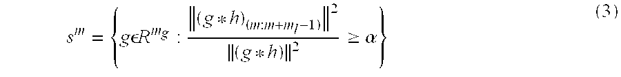
- the energy of the effective impulse response must be localized to a contiguous region of target length m l , where m l ⁇ m c , while satisfying a spectral constraint.
- the energy criterion to be satisfied by the SCISF may be written as: ⁇ ( g * h ) ( m : m + m l - 1 ) ⁇ 2 ⁇ ( g * h ) ⁇ 2 ⁇ ⁇ ( 2 )
- the impulse response of the SCISF must belong to S m for some m.
- ⁇ 1 , . . . , ⁇ N be the location of the sub-carriers in the frequency domain.
- optimization would have to be repeated for all possible m to select the filter impulse response, g, that achieves the lowest possible value of J.
- optimization may be limited to a few well chosen values of m.
- the determination of the filter impulse response may be done in two stages. First, the desired magnitude frequency response G d ( ⁇ ) of the impulse shortening filter g over the bins used by the DMT system is obtained. Second, J is optimized over S m for a specific value of m.
- the DMT system has M tones (subcarriers), N of which (those from M 1 through M 2 ) are used, and the communication channel has an analog frequency response H c ( ⁇ ).
- the analog noise power spectral density observed at the input of the receiver A/D is S ⁇ ( ⁇ ).
- the received analog signal Prior to conversion in the A/D converter, the received analog signal may be filtered by an anti-aliasing filter with transfer function H ⁇ ( ⁇ ).
- the EDIR in the absence of the impulse shortening filter is h(n).
- the signal is fed into the impulse shortening filter with an impulse response of g(n).
- the impulse shortening filter ensures that (h(n)*g(n)) is shorter in length than the cyclic prefix.
- G( ⁇ ) is the discrete time Fourier transform of g(n).
- ⁇ ⁇ ( k ) C 1 ⁇ D k ⁇ ⁇ H ⁇ ( ⁇ ⁇ ⁇ k M ) ⁇ 2 ⁇ ⁇ G ⁇ ( ⁇ ⁇ ⁇ k M ) ⁇ 2 ;
- H ⁇ ( ⁇ ) H c ⁇ ( ⁇ 2 ⁇ ⁇ ⁇ ⁇ T ) ⁇ H a ⁇ ( ⁇ 2 ⁇ ⁇ ⁇ ⁇ T ) ( 5 )
- M 1 . . . M 2 are the used tones and C 3 another constant.
- x ⁇ ⁇ [ ⁇ G ⁇ ( ⁇ ⁇ ⁇ M 1 M ) ⁇ 2 ⁇ ⁇ G ⁇ ( ⁇ ⁇ ⁇ M 2 M ) ⁇ 2 ] , ( 9 )
- the SNR in bin k can be seen to be of the form b k ⁇ x k a k T ⁇ x ,
- a median filter may be applied to the output of the optimization algorithm to smooth the resulting target spectral response.
- Matrix A has full column rank, since it corresponds to a full convolution, so R A ⁇ A T A is invertible.
- the next step is to reduce the dimensionality, i.e., the number of variables to search over in the optimization process.
- dimensionality i.e., the number of variables to search over in the optimization process.
- VDSL video digital subscriber line
- an impulse shortening filter having a few hundred taps may be required. Searching over a variable space so large is difficult and impractical. Instead, the optimization is performed by searching over a cleverly chosen lower-dimensional subset of the variable space. This simplification in the optimization process may be done without significant reduction in the performance of the communication system.
- D R FAR A ⁇ 0.5 U l .
- D R real(D) and D I ⁇ imag(D).
- D R and D I are real matrices of size (N l m d ).
- d T R,n , 1 ⁇ n ⁇ N and d T l,n , 1 ⁇ n ⁇ N be the rows of D R and D l , respectively.
- Equation (25) may be written as a polynomial equation of order 2m d in ⁇ .
- the polynomial equation must be solved for the real and positive roots, which may be done using one of the variety of efficient root-finding algorithms in the literature.
- One of the real, positive roots must be chosen by enumeration so that, when substituted into the expression for v, it leads to the smallest ⁇ y ⁇ v ⁇ 2 .
- the optimization can be done very efficiently.
- the penalty method may be used, as described in Bertsekas, Nonlinear Programming , Athena Scientific, Belmont, Mass., 1995, or an iterative strategy consisting of gradient descent followed by projection onto V. Both techniques have been tested and perform well.
Abstract
Description


Claims (24)
Priority Applications (15)
| Application Number | Priority Date | Filing Date | Title |
|---|---|---|---|
| US09/054,468 US6631175B2 (en) | 1998-04-03 | 1998-04-03 | Spectrally constrained impulse shortening filter for a discrete multi-tone receiver |
| EP99915260A EP1068704B1 (en) | 1998-04-03 | 1999-04-05 | Filter for impulse response shortening, with additional spectral constraints, for multicarrier transmission |
| EP10185268A EP2285054A1 (en) | 1998-04-03 | 1999-04-05 | Filter for impulse response shortening, with additional spectral constraints, for multicarrier transmission |
| PCT/US1999/007422 WO1999052250A1 (en) | 1998-04-03 | 1999-04-05 | Filter for impulse response shortening, with addition spectral constraints, for multicarrier transmission |
| CA2722546A CA2722546C (en) | 1998-04-03 | 1999-04-05 | Filter for impulse response shortening, with addition spectral constraints, for multicarrier transmission |
| CA2599598A CA2599598C (en) | 1998-04-03 | 1999-04-05 | Filter for impulse response shortening, with addition spectral constraints, for multicarrier transmission |
| AU33816/99A AU3381699A (en) | 1998-04-03 | 1999-04-05 | Filter for impulse response shortening, with addition spectral constraints, for multicarrier transmission |
| CA002327678A CA2327678C (en) | 1998-04-03 | 1999-04-05 | Filter for impulse response shortening, with addition spectral constraints, for multicarrier transmission |
| ES99915260T ES2389626T3 (en) | 1998-04-03 | 1999-04-05 | Shortening filter for impulse response, with additional spectral restrictions, for transmission of multiple carriers |
| DK99915260.6T DK1068704T3 (en) | 1998-04-03 | 1999-04-05 | Impulse response shortening filter, with additional spectral constraints, for multi-wave transfer |
| US10/608,329 US7254178B2 (en) | 1998-04-03 | 2003-06-27 | Spectrally constrained impulse shortening filter for a discrete multi-tone receiver |
| US11/759,789 US7430242B2 (en) | 1998-04-03 | 2007-06-07 | Spectrally constrained impulse shortening filter for a discrete multi-tone receiver |
| US12/238,140 US8102928B2 (en) | 1998-04-03 | 2008-09-25 | Spectrally constrained impulse shortening filter for a discrete multi-tone receiver |
| US13/374,524 US20120183034A1 (en) | 1998-04-03 | 2011-12-30 | Spectrally constrained impulse shortening filter for a discrete multi-tone receiver |
| US13/730,025 US9014250B2 (en) | 1998-04-03 | 2012-12-28 | Filter for impulse response shortening with additional spectral constraints for multicarrier transmission |
Applications Claiming Priority (1)
| Application Number | Priority Date | Filing Date | Title |
|---|---|---|---|
| US09/054,468 US6631175B2 (en) | 1998-04-03 | 1998-04-03 | Spectrally constrained impulse shortening filter for a discrete multi-tone receiver |
Related Parent Applications (1)
| Application Number | Title | Priority Date | Filing Date |
|---|---|---|---|
| US13/374,524 Continuation-In-Part US20120183034A1 (en) | 1998-04-03 | 2011-12-30 | Spectrally constrained impulse shortening filter for a discrete multi-tone receiver |
Related Child Applications (1)
| Application Number | Title | Priority Date | Filing Date |
|---|---|---|---|
| US10/608,329 Continuation US7254178B2 (en) | 1998-04-03 | 2003-06-27 | Spectrally constrained impulse shortening filter for a discrete multi-tone receiver |
Publications (2)
| Publication Number | Publication Date |
|---|---|
| US20020106035A1 US20020106035A1 (en) | 2002-08-08 |
| US6631175B2 true US6631175B2 (en) | 2003-10-07 |
Family
ID=21991290
Family Applications (5)
| Application Number | Title | Priority Date | Filing Date |
|---|---|---|---|
| US09/054,468 Expired - Lifetime US6631175B2 (en) | 1998-04-03 | 1998-04-03 | Spectrally constrained impulse shortening filter for a discrete multi-tone receiver |
| US10/608,329 Expired - Fee Related US7254178B2 (en) | 1998-04-03 | 2003-06-27 | Spectrally constrained impulse shortening filter for a discrete multi-tone receiver |
| US11/759,789 Expired - Fee Related US7430242B2 (en) | 1998-04-03 | 2007-06-07 | Spectrally constrained impulse shortening filter for a discrete multi-tone receiver |
| US12/238,140 Expired - Fee Related US8102928B2 (en) | 1998-04-03 | 2008-09-25 | Spectrally constrained impulse shortening filter for a discrete multi-tone receiver |
| US13/374,524 Abandoned US20120183034A1 (en) | 1998-04-03 | 2011-12-30 | Spectrally constrained impulse shortening filter for a discrete multi-tone receiver |
Family Applications After (4)
| Application Number | Title | Priority Date | Filing Date |
|---|---|---|---|
| US10/608,329 Expired - Fee Related US7254178B2 (en) | 1998-04-03 | 2003-06-27 | Spectrally constrained impulse shortening filter for a discrete multi-tone receiver |
| US11/759,789 Expired - Fee Related US7430242B2 (en) | 1998-04-03 | 2007-06-07 | Spectrally constrained impulse shortening filter for a discrete multi-tone receiver |
| US12/238,140 Expired - Fee Related US8102928B2 (en) | 1998-04-03 | 2008-09-25 | Spectrally constrained impulse shortening filter for a discrete multi-tone receiver |
| US13/374,524 Abandoned US20120183034A1 (en) | 1998-04-03 | 2011-12-30 | Spectrally constrained impulse shortening filter for a discrete multi-tone receiver |
Country Status (2)
| Country | Link |
|---|---|
| US (5) | US6631175B2 (en) |
| CA (1) | CA2599598C (en) |
Cited By (51)
| Publication number | Priority date | Publication date | Assignee | Title |
|---|---|---|---|---|
| US20010007580A1 (en) * | 2000-01-11 | 2001-07-12 | Gerd Heinrich | Method and device for processing signals of a digital transmission system |
| US20040071118A1 (en) * | 2002-09-10 | 2004-04-15 | Dabak Anand G. | Multi-carrier reception for ultra-wideband (UWB) systems |
| US6751262B1 (en) * | 1999-01-07 | 2004-06-15 | Polytrax Information Technology Akgiengesellschaft | Data transmission method |
| US20040170228A1 (en) * | 2000-08-31 | 2004-09-02 | Nokia Corporation | Frequency domain partial response signaling with high spectral efficiency and low peak to average power ratio |
| US6810007B1 (en) * | 1999-03-26 | 2004-10-26 | Samsung Electronics Co., Ltd. | OFDM transmission/receiving system and block encoding method therefor |
| US20050031064A1 (en) * | 2001-01-16 | 2005-02-10 | Kolze Thomas J. | System and method for canceling interference in a communication system |
| US6952394B1 (en) * | 1999-05-25 | 2005-10-04 | Samsung Electronics Co., Ltd. | Method for transmitting and receiving orthogonal frequency division multiplexing signal and apparatus therefor |
| US20050220178A1 (en) * | 2004-04-02 | 2005-10-06 | Texas Instruments Incorporated | Semi-distributed power spectrum control for digital subscriber line communications |
| US6999503B1 (en) * | 2000-08-31 | 2006-02-14 | Nokia Mobile Phones Ltd. | Partial response signaling for orthogonal frequency division multiplexing |
| US20060115012A1 (en) * | 2004-12-01 | 2006-06-01 | John Sadowsky | Increased discrete point processing in an OFDM communication system |
| US7058141B1 (en) * | 2000-06-02 | 2006-06-06 | Nec Usa, Inc. | MLSE decoding of PRS type inter-bin interference in receiver-end windowed DMT system |
| US7076010B1 (en) * | 2000-06-06 | 2006-07-11 | Ikanos Communication, Inc. | Method and apparatus for time domain equalization in an XDSL modem |
| USRE39693E1 (en) | 2002-02-27 | 2007-06-12 | Lecroy Corporation | Digital frequency response compensator and arbitrary response generator system |
| US20070211786A1 (en) * | 1998-02-12 | 2007-09-13 | Steve Shattil | Multicarrier Sub-Layer for Direct Sequence Channel and Multiple-Access Coding |
| US20070230562A1 (en) * | 1998-04-03 | 2007-10-04 | Tellabs Operations, Inc. | Spectrally constrained impulse shortening filter for a discrete multi-tone receiver |
| US20070297499A1 (en) * | 2006-06-21 | 2007-12-27 | Acorn Technologies, Inc. | Efficient channel shortening in communication systems |
| US7388930B1 (en) * | 2001-08-10 | 2008-06-17 | Bandspeed, Inc. | Method and apparatus for removing crosstalk and other interference in communications systems |
| US20090110033A1 (en) * | 1998-02-12 | 2009-04-30 | Lot 41 Acquisition Foundation, Llc | Multicarrier sub-layer for direct sequence channel and multiple-access coding |
| US20100104035A1 (en) * | 1996-08-22 | 2010-04-29 | Marchok Daniel J | Apparatus and method for clock synchronization in a multi-point OFDM/DMT digital communications system |
| US7813439B2 (en) | 2006-02-06 | 2010-10-12 | Broadcom Corporation | Various methods and apparatuses for impulse noise detection |
| US7852950B2 (en) | 2005-02-25 | 2010-12-14 | Broadcom Corporation | Methods and apparatuses for canceling correlated noise in a multi-carrier communication system |
| US7916801B2 (en) | 1998-05-29 | 2011-03-29 | Tellabs Operations, Inc. | Time-domain equalization for discrete multi-tone systems |
| US7953163B2 (en) * | 2004-11-30 | 2011-05-31 | Broadcom Corporation | Block linear equalization in a multicarrier communication system |
| USRE42809E1 (en) | 2000-09-01 | 2011-10-04 | Lecroy Corporation | Method and apparatus for increasing bandwidth in sampled systems |
| CN102484549A (en) * | 2009-07-17 | 2012-05-30 | 日本电信电话株式会社 | Method for receiving frequency domain multiplexed signal and device for receiving frequency domain multiplexed signal |
| US8194722B2 (en) | 2004-10-11 | 2012-06-05 | Broadcom Corporation | Various methods and apparatuses for impulse noise mitigation |
| US20130016799A1 (en) * | 2009-12-04 | 2013-01-17 | Telefonaktiebolaget Lm Ericsson (Publ) | Detection of Radio Signals in a Receiver |
| US8472533B2 (en) | 2008-10-10 | 2013-06-25 | Broadcom Corporation | Reduced-complexity common-mode noise cancellation system for DSL |
| US8547823B2 (en) | 1996-08-22 | 2013-10-01 | Tellabs Operations, Inc. | OFDM/DMT/ digital communications system including partial sequence symbol processing |
| US9014250B2 (en) | 1998-04-03 | 2015-04-21 | Tellabs Operations, Inc. | Filter for impulse response shortening with additional spectral constraints for multicarrier transmission |
| US9154346B2 (en) | 2013-03-13 | 2015-10-06 | Nikola Alic | Method for reducing equalizer complexity in communication links |
| US9374257B2 (en) | 2005-03-18 | 2016-06-21 | Broadcom Corporation | Methods and apparatuses of measuring impulse noise parameters in multi-carrier communication systems |
| US9485063B2 (en) | 2001-04-26 | 2016-11-01 | Genghiscomm Holdings, LLC | Pre-coding in multi-user MIMO |
| US9628231B2 (en) | 2002-05-14 | 2017-04-18 | Genghiscomm Holdings, LLC | Spreading and precoding in OFDM |
| US9893774B2 (en) | 2001-04-26 | 2018-02-13 | Genghiscomm Holdings, LLC | Cloud radio access network |
| US10142082B1 (en) | 2002-05-14 | 2018-11-27 | Genghiscomm Holdings, LLC | Pre-coding in OFDM |
| US10200227B2 (en) | 2002-05-14 | 2019-02-05 | Genghiscomm Holdings, LLC | Pre-coding in multi-user MIMO |
| US10305636B1 (en) | 2004-08-02 | 2019-05-28 | Genghiscomm Holdings, LLC | Cooperative MIMO |
| US10355720B2 (en) | 2001-04-26 | 2019-07-16 | Genghiscomm Holdings, LLC | Distributed software-defined radio |
| US10425135B2 (en) | 2001-04-26 | 2019-09-24 | Genghiscomm Holdings, LLC | Coordinated multipoint systems |
| US10644916B1 (en) | 2002-05-14 | 2020-05-05 | Genghiscomm Holdings, LLC | Spreading and precoding in OFDM |
| US10880145B2 (en) | 2019-01-25 | 2020-12-29 | Genghiscomm Holdings, LLC | Orthogonal multiple access and non-orthogonal multiple access |
| US10931338B2 (en) | 2001-04-26 | 2021-02-23 | Genghiscomm Holdings, LLC | Coordinated multipoint systems |
| US11018918B1 (en) | 2017-05-25 | 2021-05-25 | Genghiscomm Holdings, LLC | Peak-to-average-power reduction for OFDM multiple access |
| US11115160B2 (en) | 2019-05-26 | 2021-09-07 | Genghiscomm Holdings, LLC | Non-orthogonal multiple access |
| US11184037B1 (en) | 2004-08-02 | 2021-11-23 | Genghiscomm Holdings, LLC | Demodulating and decoding carrier interferometry signals |
| US11196603B2 (en) | 2017-06-30 | 2021-12-07 | Genghiscomm Holdings, LLC | Efficient synthesis and analysis of OFDM and MIMO-OFDM signals |
| US11343823B2 (en) | 2020-08-16 | 2022-05-24 | Tybalt, Llc | Orthogonal multiple access and non-orthogonal multiple access |
| US11381285B1 (en) | 2004-08-02 | 2022-07-05 | Genghiscomm Holdings, LLC | Transmit pre-coding |
| US11552737B1 (en) | 2004-08-02 | 2023-01-10 | Genghiscomm Holdings, LLC | Cooperative MIMO |
| US11917604B2 (en) | 2019-01-25 | 2024-02-27 | Tybalt, Llc | Orthogonal multiple access and non-orthogonal multiple access |
Families Citing this family (14)
| Publication number | Priority date | Publication date | Assignee | Title |
|---|---|---|---|---|
| US6778611B1 (en) * | 1999-08-31 | 2004-08-17 | Broadcom Corporation | Subdimensional single-carrier modulation |
| US6529868B1 (en) * | 2000-03-28 | 2003-03-04 | Tellabs Operations, Inc. | Communication system noise cancellation power signal calculation techniques |
| US7133809B1 (en) * | 2000-04-04 | 2006-11-07 | Nortel Networks Ltd | System, device, and method for time-domain equalizer training using a two-pass auto-regressive moving average model |
| JP3387918B2 (en) * | 2000-12-04 | 2003-03-17 | 富士通株式会社 | Time equalization method and device |
| US7369603B2 (en) * | 2003-05-28 | 2008-05-06 | Intel Corporation | Compensating for spectral attenuation |
| DE102004047718B4 (en) * | 2004-09-30 | 2009-01-02 | Infineon Technologies Ag | Method and receiver circuit for reducing RFI interference |
| US8355457B2 (en) * | 2004-10-26 | 2013-01-15 | Lsi Corporation | Correction-calculation algorithm for estimation of the signal to noise ratio in high bit rate DMT modulation |
| US7596183B2 (en) * | 2006-03-29 | 2009-09-29 | Provigent Ltd. | Joint optimization of transmitter and receiver pulse-shaping filters |
| EP1940068B1 (en) * | 2006-12-27 | 2011-10-05 | ABB Technology AG | Initialization of and modem for an OFDM data transmission |
| KR100975722B1 (en) * | 2007-03-26 | 2010-08-12 | 삼성전자주식회사 | Method and system for transmitting/receiving data in a communication system |
| US20110249742A1 (en) * | 2010-04-07 | 2011-10-13 | Apple Inc. | Coupled video pre-processor and codec including reference picture filter that minimizes coding expense during pre-processing mode transitions |
| US8817918B2 (en) * | 2011-12-13 | 2014-08-26 | Vixs Systems, Inc. | Cyclic prefix and precursor joint estimation |
| US10042037B2 (en) * | 2014-02-20 | 2018-08-07 | Nestwave Sas | System and method for estimating time of arrival (TOA) |
| US20230123862A1 (en) * | 2020-03-06 | 2023-04-20 | University Of Georgia Research Foundation, Inc. | Adaptive photonic rf spectral shaper |
Citations (5)
| Publication number | Priority date | Publication date | Assignee | Title |
|---|---|---|---|---|
| WO1993026096A1 (en) | 1992-06-12 | 1993-12-23 | The Board Of Trustees Of The Leland Stanford, Junior University | Method for equalizing a multicarrier signal |
| US5521908A (en) * | 1995-04-20 | 1996-05-28 | Tellabs Operations Inc. | Method and apparatus for providing reduced complexity echo cancellation in a multicarrier communication system |
| EP0768778A1 (en) | 1995-10-11 | 1997-04-16 | ALCATEL BELL Naamloze Vennootschap | Method for transmission line impulse response equalisation and a device to perform this method |
| US6035000A (en) * | 1996-04-19 | 2000-03-07 | Amati Communications Corporation | Mitigating radio frequency interference in multi-carrier transmission systems |
| US6097763A (en) * | 1997-10-31 | 2000-08-01 | Pairgain Technologies, Inc. | MMSE equalizers for DMT systems with cross talk |
Family Cites Families (153)
| Publication number | Priority date | Publication date | Assignee | Title |
|---|---|---|---|---|
| US3795772A (en) | 1972-05-01 | 1974-03-05 | Us Navy | Synchronization system for pulse orthogonal multiplexing systems |
| JPS6039399B2 (en) | 1978-01-25 | 1985-09-05 | 株式会社日立製作所 | How to operate a washing machine |
| US4300229A (en) | 1979-02-21 | 1981-11-10 | Nippon Electric Co., Ltd. | Transmitter and receiver for an othogonally multiplexed QAM signal of a sampling rate N times that of PAM signals, comprising an N/2-point offset fourier transform processor |
| US4351983A (en) | 1979-03-05 | 1982-09-28 | International Business Machines Corp. | Speech detector with variable threshold |
| JPS567213A (en) | 1979-06-27 | 1981-01-24 | Hitachi Ltd | Noise eliminating circuit |
| US4425665A (en) | 1981-09-24 | 1984-01-10 | Advanced Micro Devices, Inc. | FSK Voiceband modem using digital filters |
| US4399329A (en) | 1981-11-25 | 1983-08-16 | Rca Corporation | Stereophonic bilingual signal processor |
| US4535472A (en) | 1982-11-05 | 1985-08-13 | At&T Bell Laboratories | Adaptive bit allocator |
| US4618996A (en) | 1984-04-24 | 1986-10-21 | Avnet, Inc. | Dual pilot phase lock loop for radio frequency transmission |
| US4679227A (en) | 1985-05-20 | 1987-07-07 | Telebit Corporation | Ensemble modem structure for imperfect transmission media |
| US4630305A (en) | 1985-07-01 | 1986-12-16 | Motorola, Inc. | Automatic gain selector for a noise suppression system |
| JPS6345933A (en) | 1986-04-15 | 1988-02-26 | Nec Corp | Privacy communication equipment |
| JPH01106639A (en) | 1987-10-20 | 1989-04-24 | Nec Corp | Transmitter-receiver for satellite communication earth station |
| US4980897A (en) | 1988-08-12 | 1990-12-25 | Telebit Corporation | Multi-channel trellis encoder/decoder |
| US5014306A (en) | 1988-11-14 | 1991-05-07 | Transtream, Inc. | Voice and data telephone communication system and method |
| US5001724A (en) | 1989-01-13 | 1991-03-19 | Hewlett-Packard Company | Method and apparatus for measuring phase accuracy and amplitude profile of a continuous-phase-modulated signal |
| JP2777194B2 (en) | 1989-05-29 | 1998-07-16 | 株式会社東芝 | Optical transmission system |
| FR2658017B1 (en) | 1990-02-06 | 1992-06-05 | France Etat | METHOD FOR BROADCASTING DIGITAL DATA, ESPECIALLY FOR BROADBAND BROADCASTING TO MOBILES, WITH TIME-FREQUENCY INTERLACING AND ASSISTING THE ACQUISITION OF AUTOMATIC FREQUENCY CONTROL, AND CORRESPONDING RECEIVER. |
| GB2244190A (en) | 1990-05-17 | 1991-11-20 | Orbitel Mobile Communications | Receiver systems with equalisers |
| US5103459B1 (en) | 1990-06-25 | 1999-07-06 | Qualcomm Inc | System and method for generating signal waveforms in a cdma cellular telephone system |
| US5568483A (en) | 1990-06-25 | 1996-10-22 | Qualcomm Incorporated | Method and apparatus for the formatting of data for transmission |
| DE4111855C2 (en) | 1991-04-11 | 1994-10-20 | Inst Rundfunktechnik Gmbh | Method for the radio transmission of a digitally coded data stream |
| BE1004813A3 (en) | 1991-05-08 | 1993-02-02 | Bell Telephone Mfg | OPTICAL TRANSMITTER / RECEIVER. |
| CA2066540C (en) | 1991-06-13 | 1998-01-20 | Edwin A. Kelley | Multiple user digital receiving apparatus and method with time division multiplexing |
| US5253270A (en) | 1991-07-08 | 1993-10-12 | Hal Communications | Apparatus useful in radio communication of digital data using minimal bandwidth |
| US5548819A (en) | 1991-12-02 | 1996-08-20 | Spectraplex, Inc. | Method and apparatus for communication of information |
| DE69322322T2 (en) | 1992-07-08 | 1999-06-17 | Koninkl Philips Electronics Nv | Chained coding for OFDM transmission |
| US6809681B1 (en) * | 1992-08-25 | 2004-10-26 | Raytheon Company | Random-modulation radar signal-induced interference cancellation method and apparatus |
| GB9218874D0 (en) | 1992-09-07 | 1992-10-21 | British Broadcasting Corp | Improvements relating to the transmission of frequency division multiplex signals |
| US5603081A (en) | 1993-11-01 | 1997-02-11 | Telefonaktiebolaget Lm Ericsson | Method for communicating in a wireless communication system |
| US5416767A (en) | 1993-02-08 | 1995-05-16 | U.S. Philips Corporation | Method of transmitting a data stream, transmitter and receiver |
| ES2159540T3 (en) | 1993-02-08 | 2001-10-16 | Koninkl Philips Electronics Nv | RECEIVER, WITH MULTIPLEXOR OF ORTOGONAL FREQUENCY DIVISION, WITH COMPENSATION FOR DIFFERENTIAL DELAYS. |
| JP3301555B2 (en) | 1993-03-30 | 2002-07-15 | ソニー株式会社 | Wireless receiver |
| US5357257A (en) * | 1993-04-05 | 1994-10-18 | General Electric Company | Apparatus and method for equalizing channels in a multi-channel communication system |
| US5479447A (en) | 1993-05-03 | 1995-12-26 | The Board Of Trustees Of The Leland Stanford, Junior University | Method and apparatus for adaptive, variable bandwidth, high-speed data transmission of a multicarrier signal over digital subscriber lines |
| JPH08511664A (en) | 1993-06-07 | 1996-12-03 | アルカテル・モビル・フオンズ | Signal packet for a communication system having a reference modulated according to a time-dependent law |
| JPH0746217A (en) | 1993-07-26 | 1995-02-14 | Sony Corp | Digital demodulator |
| US5675572A (en) | 1993-07-28 | 1997-10-07 | Sony Corporation | Orthogonal frequency division multiplex modulation apparatus and orthogonal frequency division multiplex demodulation apparatus |
| JP3041175B2 (en) | 1993-11-12 | 2000-05-15 | 株式会社東芝 | OFDM synchronous demodulation circuit |
| JP3074103B2 (en) | 1993-11-16 | 2000-08-07 | 株式会社東芝 | OFDM synchronous demodulation circuit |
| US5559789A (en) | 1994-01-31 | 1996-09-24 | Matsushita Electric Industrial Co., Ltd. | CDMA/TDD Radio Communication System |
| US5524001A (en) | 1994-02-07 | 1996-06-04 | Le Groupe Videotron Ltee | Dynamic cable signal assembly |
| JPH07264214A (en) | 1994-02-07 | 1995-10-13 | Fujitsu Ltd | Interface device |
| US5566209A (en) | 1994-02-10 | 1996-10-15 | Telefonaktiebolaget Lm Ericsson | Transceiver algorithms of antenna arrays |
| US5684920A (en) | 1994-03-17 | 1997-11-04 | Nippon Telegraph And Telephone | Acoustic signal transform coding method and decoding method having a high efficiency envelope flattening method therein |
| US5553064A (en) | 1994-04-05 | 1996-09-03 | Stanford Telecommunications, Inc. | High speed bidirectional digital cable transmission system |
| DE69534067T2 (en) | 1994-05-09 | 2006-04-13 | Victor Company of Japan, Ltd., Yokohama | Setting a reference subcarrier in multi-carrier transmission |
| JP2731722B2 (en) | 1994-05-26 | 1998-03-25 | 日本電気株式会社 | Clock frequency automatic control system and transmitter and receiver used therefor |
| FI96154C (en) | 1994-05-30 | 1996-05-10 | Nokia Telecommunications Oy | Method for synchronizing subscriber terminals, base station and subscriber terminal |
| US5557612A (en) | 1995-01-20 | 1996-09-17 | Amati Communications Corporation | Method and apparatus for establishing communication in a multi-tone data transmission system |
| US5625651A (en) | 1994-06-02 | 1997-04-29 | Amati Communications, Inc. | Discrete multi-tone data transmission system using an overhead bus for synchronizing multiple remote units |
| US5461640A (en) | 1994-06-03 | 1995-10-24 | Texas Instruments Incorporated | Method and system for optimizing an equalizer in a data transmission system |
| KR100326312B1 (en) | 1994-06-17 | 2002-06-22 | 윤종용 | Synchronous transceiver of spread spectrum communication manner |
| US5627863A (en) | 1994-07-15 | 1997-05-06 | Amati Communications Corporation | Frame synchronization in multicarrier transmission systems |
| US5594757A (en) | 1994-07-28 | 1997-01-14 | Motorola, Inc. | Method and apparatus for digital automatic frequency control |
| US6334219B1 (en) | 1994-09-26 | 2001-12-25 | Adc Telecommunications Inc. | Channel selection for a hybrid fiber coax network |
| US5864683A (en) | 1994-10-12 | 1999-01-26 | Secure Computing Corporartion | System for providing secure internetwork by connecting type enforcing secure computers to external network for limiting access to data based on user and process access rights |
| FR2726417A1 (en) | 1994-10-26 | 1996-05-03 | Philips Electronique Lab | TRANSMISSION AND RECEIVER SYSTEM OF SIGNALS WITH MULTIPLEXED SPEECHOGONAL FREQUENCY DISTRIBUTION EQUIPPED WITH A FREQUENCY SYNCHRONIZATION DEVICE |
| US5636246A (en) | 1994-11-16 | 1997-06-03 | Aware, Inc. | Multicarrier transmission system |
| US5621455A (en) | 1994-12-01 | 1997-04-15 | Objective Communications, Inc. | Video modem for transmitting video data over ordinary telephone wires |
| US5682376A (en) | 1994-12-20 | 1997-10-28 | Matsushita Electric Industrial Co., Ltd. | Method of transmitting orthogonal frequency division multiplex signal, and transmitter and receiver employed therefor |
| US5774450A (en) | 1995-01-10 | 1998-06-30 | Matsushita Electric Industrial Co., Ltd. | Method of transmitting orthogonal frequency division multiplexing signal and receiver thereof |
| US5608725A (en) | 1995-01-26 | 1997-03-04 | Motorola, Inc. | Method and apparatus of a communications system having a DMT infrastructure |
| US5539777A (en) | 1995-01-26 | 1996-07-23 | Motorola, Inc. | Method and apparatus for a DMT receiver having a data de-formatter coupled directly to a constellation decoder |
| SE514986C2 (en) | 1995-03-01 | 2001-05-28 | Telia Ab | Method and device for synchronization with OFDM systems |
| US5708662A (en) | 1995-04-07 | 1998-01-13 | Casio Computer Co., Ltd. | Transmission method and receiving apparatus of emergency information which is frequency-multiplexed on an FM broadcast radio wave |
| JP2778513B2 (en) | 1995-04-14 | 1998-07-23 | 日本電気株式会社 | Echo canceller device |
| GB9510127D0 (en) | 1995-05-20 | 1995-08-02 | West End System Corp | CATV Data transmission system |
| US6018317A (en) * | 1995-06-02 | 2000-01-25 | Trw Inc. | Cochannel signal processing system |
| US5726978A (en) | 1995-06-22 | 1998-03-10 | Telefonaktiebolaget L M Ericsson Publ. | Adaptive channel allocation in a frequency division multiplexed system |
| US5790516A (en) | 1995-07-14 | 1998-08-04 | Telefonaktiebolaget Lm Ericsson | Pulse shaping for data transmission in an orthogonal frequency division multiplexed system |
| US5867764A (en) | 1995-09-01 | 1999-02-02 | Cable Television Laboratories, Inc. | Hybrid return gate system in a bidirectional cable network |
| US5815488A (en) | 1995-09-28 | 1998-09-29 | Cable Television Laboratories, Inc. | Multiple user access method using OFDM |
| US5790554A (en) | 1995-10-04 | 1998-08-04 | Bay Networks, Inc. | Method and apparatus for processing data packets in a network |
| US6125150A (en) | 1995-10-30 | 2000-09-26 | The Board Of Trustees Of The Leland Stanford, Junior University | Transmission system using code designed for transmission with periodic interleaving |
| US5790615A (en) | 1995-12-11 | 1998-08-04 | Delco Electronics Corporation | Digital phase-lock loop network |
| US5828710A (en) | 1995-12-11 | 1998-10-27 | Delco Electronics Corporation | AFC frequency synchronization network |
| KR970068393A (en) | 1996-03-11 | 1997-10-13 | 김광호 | Apparatus and method for restoring sampling clock of a receiving terminal of a discrete multi-tone system |
| FI100150B (en) * | 1996-03-19 | 1997-09-30 | Nokia Telecommunications Oy | Reception method and receiver |
| EP0800285B1 (en) | 1996-04-04 | 2005-12-14 | Siemens Aktiengesellschaft | Method for adjusting the parameters of a receiving apparatus, as well as corresponding receiving apparatus and radio station |
| US5862007A (en) | 1996-04-18 | 1999-01-19 | Samsung Electronics Co., Ltd. | Method and apparatus for removing baseline shifts in a read signal using filters |
| US6044107A (en) | 1996-05-09 | 2000-03-28 | Texas Instruments Incorporated | Method for interoperability of a T1E1.4 compliant ADSL modem and a simpler modem |
| US6002722A (en) | 1996-05-09 | 1999-12-14 | Texas Instruments Incorporated | Multimode digital modem |
| US5949796A (en) | 1996-06-19 | 1999-09-07 | Kumar; Derek D. | In-band on-channel digital broadcasting method and system |
| US6028891A (en) | 1996-06-25 | 2000-02-22 | Analog Devices, Inc. | Asymmetric digital subscriber loop transceiver and method |
| JP4008035B2 (en) | 1996-06-28 | 2007-11-14 | コーニンクレッカ、フィリップス、エレクトロニクス、エヌ.ヴィ・ | Method for simplifying demodulation in multi-carrier transmission systems |
| US5918019A (en) | 1996-07-29 | 1999-06-29 | Cisco Technology, Inc. | Virtual dial-up protocol for network communication |
| US6073176A (en) | 1996-07-29 | 2000-06-06 | Cisco Technology, Inc. | Dynamic bidding protocol for conducting multilink sessions through different physical termination points |
| US6141317A (en) | 1996-08-22 | 2000-10-31 | Tellabs Operations, Inc. | Apparatus and method for bandwidth management in a multi-point OFDM/DMT digital communications system |
| US5790514A (en) | 1996-08-22 | 1998-08-04 | Tellabs Operations, Inc. | Multi-point OFDM/DMT digital communications system including remote service unit with improved receiver architecture |
| US6771590B1 (en) | 1996-08-22 | 2004-08-03 | Tellabs Operations, Inc. | Communication system clock synchronization techniques |
| US6118758A (en) | 1996-08-22 | 2000-09-12 | Tellabs Operations, Inc. | Multi-point OFDM/DMT digital communications system including remote service unit with improved transmitter architecture |
| US6950388B2 (en) | 1996-08-22 | 2005-09-27 | Tellabs Operations, Inc. | Apparatus and method for symbol alignment in a multi-point OFDM/DMT digital communications system |
| US5995483A (en) | 1996-08-22 | 1999-11-30 | Tellabs Operations, Inc. | Apparatus and method for upstream clock synchronization in a multi-point OFDM/DMT digital communication system |
| US6122246A (en) | 1996-08-22 | 2000-09-19 | Tellabs Operations, Inc. | Apparatus and method for clock synchronization in a multi-point OFDM/DMT digital communications system |
| US6108349A (en) | 1996-08-22 | 2000-08-22 | Tellabs Operations, Inc. | Method and apparatus for registering remote service units in a multipoint communication system |
| US6285654B1 (en) | 1996-08-22 | 2001-09-04 | Tellabs Operations, Inc. | Apparatus and method for symbol alignment in a multi-point OFDM or DMT digital communications system |
| US5841813A (en) | 1996-09-04 | 1998-11-24 | Lucent Technologies Inc. | Digital communications system using complementary codes and amplitude modulation |
| US5850444A (en) | 1996-09-09 | 1998-12-15 | Telefonaktienbolaget L/M Ericsson (Publ) | Method and apparatus for encrypting radio traffic in a telecommunications network |
| US5995568A (en) | 1996-10-28 | 1999-11-30 | Motorola, Inc. | Method and apparatus for performing frame synchronization in an asymmetrical digital subscriber line (ADSL) system |
| US6075816A (en) * | 1996-11-27 | 2000-06-13 | Lucent Technologies, Inc. | Windowing technique for blind equalization |
| US5909465A (en) * | 1996-12-05 | 1999-06-01 | Ericsson Inc. | Method and apparatus for bidirectional demodulation of digitally modulated signals |
| US5984514A (en) | 1996-12-20 | 1999-11-16 | Analog Devices, Inc. | Method and apparatus for using minimal and optimal amount of SRAM delay line storage in the calculation of an X Y separable mallat wavelet transform |
| US6072782A (en) | 1996-12-23 | 2000-06-06 | Texas Instruments Incorporated | Efficient echo cancellation for DMT MDSL |
| US6320902B1 (en) * | 1996-12-23 | 2001-11-20 | Texas Instruments Incorporated | Time domain equalizer for ADSL |
| US6055575A (en) | 1997-01-28 | 2000-04-25 | Ascend Communications, Inc. | Virtual private network system and method |
| US6370156B2 (en) | 1997-01-31 | 2002-04-09 | Alcatel | Modulation/demodulation of a pilot carrier, means and method to perform the modulation/demodulation |
| US6128276A (en) | 1997-02-24 | 2000-10-03 | Radix Wireless, Inc. | Stacked-carrier discrete multiple tone communication technology and combinations with code nulling, interference cancellation, retrodirective communication and adaptive antenna arrays |
| US6148024A (en) | 1997-03-04 | 2000-11-14 | At&T Corporation | FFT-based multitone DPSK modem |
| US6272108B1 (en) | 1997-03-05 | 2001-08-07 | Paradyne Corporation | Apparatus and method to allow a frame check sequence to determine the updating of adaptive receiver parameters of a high speed communication device |
| US5912920A (en) | 1997-03-27 | 1999-06-15 | Marchok; Daniel J. | Point-to multipoint digital communications system facilitating use of a reduced complexity receiver at each of the multipoint sites |
| US6353629B1 (en) | 1997-05-12 | 2002-03-05 | Texas Instruments Incorporated | Poly-path time domain equalization |
| US6069917A (en) * | 1997-05-23 | 2000-05-30 | Lucent Technologies Inc. | Blind training of a decision feedback equalizer |
| US6134591A (en) | 1997-06-18 | 2000-10-17 | Client/Server Technologies, Inc. | Network security and integration method and system |
| US6073179A (en) | 1997-06-30 | 2000-06-06 | Integrated Telecom Express | Program for controlling DMT based modem using sub-channel selection to achieve scaleable data rate based on available signal processing resources |
| US6466557B1 (en) | 1997-07-14 | 2002-10-15 | Sanyo Electric Co., Ltd. | Transmission channel allocation method and allocation apparatus |
| US6212635B1 (en) | 1997-07-18 | 2001-04-03 | David C. Reardon | Network security system allowing access and modification to a security subsystem after initial installation when a master token is in place |
| US6061796A (en) | 1997-08-26 | 2000-05-09 | V-One Corporation | Multi-access virtual private network |
| JP3132448B2 (en) | 1997-12-19 | 2001-02-05 | 日本電気株式会社 | Training method and training circuit for adaptive equalizer tap coefficients |
| US6023674A (en) | 1998-01-23 | 2000-02-08 | Telefonaktiebolaget L M Ericsson | Non-parametric voice activity detection |
| US6079020A (en) | 1998-01-27 | 2000-06-20 | Vpnet Technologies, Inc. | Method and apparatus for managing a virtual private network |
| US6513117B2 (en) | 1998-03-04 | 2003-01-28 | Gemstar Development Corporation | Certificate handling for digital rights management system |
| US7032242B1 (en) | 1998-03-05 | 2006-04-18 | 3Com Corporation | Method and system for distributed network address translation with network security features |
| US6185251B1 (en) | 1998-03-27 | 2001-02-06 | Telefonaktiebolaget Lm Ericsson | Equalizer for use in multi-carrier modulation systems |
| US6526105B1 (en) | 1998-05-29 | 2003-02-25 | Tellabs, Operations, Inc. | Time domain equalization for discrete multi-tone systems |
| US7440498B2 (en) | 2002-12-17 | 2008-10-21 | Tellabs Operations, Inc. | Time domain equalization for discrete multi-tone systems |
| US6631175B2 (en) * | 1998-04-03 | 2003-10-07 | Tellabs Operations, Inc. | Spectrally constrained impulse shortening filter for a discrete multi-tone receiver |
| US6154839A (en) | 1998-04-23 | 2000-11-28 | Vpnet Technologies, Inc. | Translating packet addresses based upon a user identifier |
| US6266367B1 (en) | 1998-05-28 | 2001-07-24 | 3Com Corporation | Combined echo canceller and time domain equalizer |
| US6557037B1 (en) | 1998-05-29 | 2003-04-29 | Sun Microsystems | System and method for easing communications between devices connected respectively to public networks such as the internet and to private networks by facilitating resolution of human-readable addresses |
| FI981319A (en) * | 1998-06-10 | 1999-12-11 | Nokia Networks Oy | Separation of narrowband and broadband services on a transmission connection |
| US6108610A (en) | 1998-10-13 | 2000-08-22 | Noise Cancellation Technologies, Inc. | Method and system for updating noise estimates during pauses in an information signal |
| US6279022B1 (en) | 1998-11-13 | 2001-08-21 | Integrated Telecom Express, Inc. | System and method for detecting symbol boundary in multi-carrier transmission systems |
| US6584096B1 (en) | 1998-12-30 | 2003-06-24 | Nortel Networks Limited | Method and apparatus for connecting a home network to the internet |
| US6654429B1 (en) | 1998-12-31 | 2003-11-25 | At&T Corp. | Pilot-aided channel estimation for OFDM in wireless systems |
| US6487252B1 (en) | 1999-01-29 | 2002-11-26 | Motorola, Inc. | Wireless communication system and method for synchronization |
| ATE496452T1 (en) | 1999-02-19 | 2011-02-15 | Nokia Siemens Networks Oy | NETWORK ARRANGEMENT FOR COMMUNICATION |
| US6347237B1 (en) | 1999-03-16 | 2002-02-12 | Superconductor Technologies, Inc. | High temperature superconductor tunable filter |
| JP2001134534A (en) | 1999-11-08 | 2001-05-18 | Ntt Communications Kk | Authentication delegate method, authentication delegate service system, authentication delegate server device, and client device |
| US7058572B1 (en) | 2000-01-28 | 2006-06-06 | Nortel Networks Limited | Reducing acoustic noise in wireless and landline based telephony |
| JP3570327B2 (en) | 2000-02-22 | 2004-09-29 | 日本電気株式会社 | Proxy encryption communication system and method, and recording medium recording program |
| KR100847596B1 (en) | 2000-03-02 | 2008-07-21 | 소니 가부시끼 가이샤 | Communication network system, gateway, data communication method and program providing medium |
| US6529868B1 (en) | 2000-03-28 | 2003-03-04 | Tellabs Operations, Inc. | Communication system noise cancellation power signal calculation techniques |
| JP2002077274A (en) | 2000-08-31 | 2002-03-15 | Toshiba Corp | Home gateway device, access server and communication method |
| US6765881B1 (en) | 2000-12-06 | 2004-07-20 | Covad Communications Group, Inc. | Virtual L2TP/VPN tunnel network and spanning tree-based method for discovery of L2TP/VPN tunnels and other layer-2 services |
| US7251824B2 (en) | 2000-12-19 | 2007-07-31 | Intel Corporation | Accessing a private network |
| KR100708467B1 (en) | 2001-02-03 | 2007-04-18 | 삼성전자주식회사 | System for providing service with device in home network and method thereof |
| US7617099B2 (en) | 2001-02-12 | 2009-11-10 | FortMedia Inc. | Noise suppression by two-channel tandem spectrum modification for speech signal in an automobile |
| US7010608B2 (en) | 2001-09-28 | 2006-03-07 | Intel Corporation | System and method for remotely accessing a home server while preserving end-to-end security |
| KR100412041B1 (en) * | 2002-01-04 | 2003-12-24 | 삼성전자주식회사 | Home Gateway and method for executing security protocol function |
| US20040240669A1 (en) | 2002-02-19 | 2004-12-02 | James Kempf | Securing neighbor discovery using address based keys |
| US6971017B2 (en) | 2002-04-16 | 2005-11-29 | Xerox Corporation | Ad hoc secure access to documents and services |
| WO2006119184A2 (en) | 2005-05-04 | 2006-11-09 | Tricipher, Inc. | Protecting one-time-passwords against man-in-the-middle attacks |
-
1998
- 1998-04-03 US US09/054,468 patent/US6631175B2/en not_active Expired - Lifetime
-
1999
- 1999-04-05 CA CA2599598A patent/CA2599598C/en not_active Expired - Fee Related
-
2003
- 2003-06-27 US US10/608,329 patent/US7254178B2/en not_active Expired - Fee Related
-
2007
- 2007-06-07 US US11/759,789 patent/US7430242B2/en not_active Expired - Fee Related
-
2008
- 2008-09-25 US US12/238,140 patent/US8102928B2/en not_active Expired - Fee Related
-
2011
- 2011-12-30 US US13/374,524 patent/US20120183034A1/en not_active Abandoned
Patent Citations (6)
| Publication number | Priority date | Publication date | Assignee | Title |
|---|---|---|---|---|
| WO1993026096A1 (en) | 1992-06-12 | 1993-12-23 | The Board Of Trustees Of The Leland Stanford, Junior University | Method for equalizing a multicarrier signal |
| US5285474A (en) * | 1992-06-12 | 1994-02-08 | The Board Of Trustees Of The Leland Stanford, Junior University | Method for equalizing a multicarrier signal in a multicarrier communication system |
| US5521908A (en) * | 1995-04-20 | 1996-05-28 | Tellabs Operations Inc. | Method and apparatus for providing reduced complexity echo cancellation in a multicarrier communication system |
| EP0768778A1 (en) | 1995-10-11 | 1997-04-16 | ALCATEL BELL Naamloze Vennootschap | Method for transmission line impulse response equalisation and a device to perform this method |
| US6035000A (en) * | 1996-04-19 | 2000-03-07 | Amati Communications Corporation | Mitigating radio frequency interference in multi-carrier transmission systems |
| US6097763A (en) * | 1997-10-31 | 2000-08-01 | Pairgain Technologies, Inc. | MMSE equalizers for DMT systems with cross talk |
Non-Patent Citations (14)
| Title |
|---|
| A. Worthen et al., Simulation of VDSL Test Loops, Technical Report T1E1.4/97-288, ANSI, 1997. |
| D. D. Falconer et al., Adaptive Channel Memory Truncation for Maximum Likelihood Sequence Estimation, Nov. 1973, vol. 52, No. 9, The Bell System Technical Journal. |
| DMT Group VDSL PMD Draft Standard Proposal, Technical Report T1E1.4/96-32R2, ANSI 1997. |
| G. Harikumar et al., Minimizing noise bleeding in DMT systems with a TEQ, Technical Report T1E1.4/98-181, ANSI 1998. |
| G. Harikumar et al., Shortening the channel impulse response of VDSL loops for multicarrier applications, Technical Report T1E1.4/97-289, ANSI 1997. |
| International Preliminary Examination Report, Aug. 13, 1999. |
| Jacky S. Chow et al., A Discrete Multitone Transceiver System for HDSL Applications, IEEE Journal on Selected Areas in Communications, vol. 9, No. 6, Aug. 1991, pp. 895-908. |
| Jacky S. Chow, et al., A Cost-Effective Maximum Likelihood Receiver for Multicarrier Systems, Proceedings of the International Conference on Communication, 1992, pp. 333.1-333.7.5. |
| Leonard J. Cimini, Jr., Analysis and Simulation of a Digital Mobile Channel Using Orthogonal Frequency Division Multiplexing, IEEE Transactions On Communications, vol. COM-33, No. 7, Jul. 1985, pp. 665-675. |
| Naofal Al-Dhahir, Joint Channel and Echo Impulse Response Shortening on Digital Subscriber Lines, Oct. 1996, vol. 3, No. 10, IEEE Signal Processing Letters. |
| Peter J. W. Melsa et al., Impulse Response Shortening for Discrete Multitone Transceivers, Dec. 1995, vol. 44, No. 12, IEEE Transactions on Communications. |
| Peter J.W. Melsa, et al., Optimal Impulse Response Shortening, Proceedings of the Thirty-third Annual Allerton Conference on Communication, Control and Computing, pp. 431-439. |
| VDSL Alliance SDMT VDSL Draft Standard Proposal, Technical Report T1E1.4/98-172, ANSI 1998. |
| Very-high-speed Digital Subscriber Lines, Draft Technical Report-Revision 9, T1E1.4/97-131, ANSI 1997. |
Cited By (107)
| Publication number | Priority date | Publication date | Assignee | Title |
|---|---|---|---|---|
| US8139471B2 (en) | 1996-08-22 | 2012-03-20 | Tellabs Operations, Inc. | Apparatus and method for clock synchronization in a multi-point OFDM/DMT digital communications system |
| US8547823B2 (en) | 1996-08-22 | 2013-10-01 | Tellabs Operations, Inc. | OFDM/DMT/ digital communications system including partial sequence symbol processing |
| US8665859B2 (en) | 1996-08-22 | 2014-03-04 | Tellabs Operations, Inc. | Apparatus and method for clock synchronization in a multi-point OFDM/DMT digital communications system |
| US20100104035A1 (en) * | 1996-08-22 | 2010-04-29 | Marchok Daniel J | Apparatus and method for clock synchronization in a multi-point OFDM/DMT digital communications system |
| US7593449B2 (en) | 1998-02-12 | 2009-09-22 | Steve Shattil | Multicarrier sub-layer for direct sequence channel and multiple-access coding |
| US20090110033A1 (en) * | 1998-02-12 | 2009-04-30 | Lot 41 Acquisition Foundation, Llc | Multicarrier sub-layer for direct sequence channel and multiple-access coding |
| US7430257B1 (en) | 1998-02-12 | 2008-09-30 | Lot 41 Acquisition Foundation, Llc | Multicarrier sub-layer for direct sequence channel and multiple-access coding |
| US7965761B2 (en) | 1998-02-12 | 2011-06-21 | Lot 41 Acquisition Foundation, Llc | Multicarrier sub-layer for direct sequence channel and multiple-access coding |
| US20070211786A1 (en) * | 1998-02-12 | 2007-09-13 | Steve Shattil | Multicarrier Sub-Layer for Direct Sequence Channel and Multiple-Access Coding |
| US7430242B2 (en) * | 1998-04-03 | 2008-09-30 | Tellabs Operations, Inc. | Spectrally constrained impulse shortening filter for a discrete multi-tone receiver |
| US8102928B2 (en) | 1998-04-03 | 2012-01-24 | Tellabs Operations, Inc. | Spectrally constrained impulse shortening filter for a discrete multi-tone receiver |
| US20070230562A1 (en) * | 1998-04-03 | 2007-10-04 | Tellabs Operations, Inc. | Spectrally constrained impulse shortening filter for a discrete multi-tone receiver |
| US9014250B2 (en) | 1998-04-03 | 2015-04-21 | Tellabs Operations, Inc. | Filter for impulse response shortening with additional spectral constraints for multicarrier transmission |
| US8315299B2 (en) | 1998-05-29 | 2012-11-20 | Tellabs Operations, Inc. | Time-domain equalization for discrete multi-tone systems |
| US7916801B2 (en) | 1998-05-29 | 2011-03-29 | Tellabs Operations, Inc. | Time-domain equalization for discrete multi-tone systems |
| US6751262B1 (en) * | 1999-01-07 | 2004-06-15 | Polytrax Information Technology Akgiengesellschaft | Data transmission method |
| US6810007B1 (en) * | 1999-03-26 | 2004-10-26 | Samsung Electronics Co., Ltd. | OFDM transmission/receiving system and block encoding method therefor |
| US6952394B1 (en) * | 1999-05-25 | 2005-10-04 | Samsung Electronics Co., Ltd. | Method for transmitting and receiving orthogonal frequency division multiplexing signal and apparatus therefor |
| US20010007580A1 (en) * | 2000-01-11 | 2001-07-12 | Gerd Heinrich | Method and device for processing signals of a digital transmission system |
| US6845133B2 (en) * | 2000-01-11 | 2005-01-18 | Lucent Technologies Inc. | Method and device for processing signals of a digital transmission system |
| US7058141B1 (en) * | 2000-06-02 | 2006-06-06 | Nec Usa, Inc. | MLSE decoding of PRS type inter-bin interference in receiver-end windowed DMT system |
| US7076010B1 (en) * | 2000-06-06 | 2006-07-11 | Ikanos Communication, Inc. | Method and apparatus for time domain equalization in an XDSL modem |
| US20040170228A1 (en) * | 2000-08-31 | 2004-09-02 | Nokia Corporation | Frequency domain partial response signaling with high spectral efficiency and low peak to average power ratio |
| US7173961B2 (en) * | 2000-08-31 | 2007-02-06 | Nokia Corporation | Frequency domain partial response signaling with high spectral efficiency and low peak to average power ratio |
| US6999503B1 (en) * | 2000-08-31 | 2006-02-14 | Nokia Mobile Phones Ltd. | Partial response signaling for orthogonal frequency division multiplexing |
| USRE42809E1 (en) | 2000-09-01 | 2011-10-04 | Lecroy Corporation | Method and apparatus for increasing bandwidth in sampled systems |
| US7218694B2 (en) * | 2001-01-16 | 2007-05-15 | Broadcom Corporation | System and method for canceling interference in a communication system |
| US20050031064A1 (en) * | 2001-01-16 | 2005-02-10 | Kolze Thomas J. | System and method for canceling interference in a communication system |
| US10931338B2 (en) | 2001-04-26 | 2021-02-23 | Genghiscomm Holdings, LLC | Coordinated multipoint systems |
| US9893774B2 (en) | 2001-04-26 | 2018-02-13 | Genghiscomm Holdings, LLC | Cloud radio access network |
| US9485063B2 (en) | 2001-04-26 | 2016-11-01 | Genghiscomm Holdings, LLC | Pre-coding in multi-user MIMO |
| US10355720B2 (en) | 2001-04-26 | 2019-07-16 | Genghiscomm Holdings, LLC | Distributed software-defined radio |
| US11424792B2 (en) | 2001-04-26 | 2022-08-23 | Genghiscomm Holdings, LLC | Coordinated multipoint systems |
| US10797732B1 (en) | 2001-04-26 | 2020-10-06 | Genghiscomm Holdings, LLC | Distributed antenna systems |
| US10425135B2 (en) | 2001-04-26 | 2019-09-24 | Genghiscomm Holdings, LLC | Coordinated multipoint systems |
| US10797733B1 (en) | 2001-04-26 | 2020-10-06 | Genghiscomm Holdings, LLC | Distributed antenna systems |
| US7388930B1 (en) * | 2001-08-10 | 2008-06-17 | Bandspeed, Inc. | Method and apparatus for removing crosstalk and other interference in communications systems |
| USRE39693E1 (en) | 2002-02-27 | 2007-06-12 | Lecroy Corporation | Digital frequency response compensator and arbitrary response generator system |
| USRE40802E1 (en) | 2002-02-27 | 2009-06-23 | Lecroy Corporation | Digital frequency response compensator and arbitrary response generator system |
| US10903970B1 (en) | 2002-05-14 | 2021-01-26 | Genghiscomm Holdings, LLC | Pre-coding in OFDM |
| US10587369B1 (en) | 2002-05-14 | 2020-03-10 | Genghiscomm Holdings, LLC | Cooperative subspace multiplexing |
| US11025312B2 (en) | 2002-05-14 | 2021-06-01 | Genghiscomm Holdings, LLC | Blind-adaptive decoding of radio signals |
| US11025468B1 (en) | 2002-05-14 | 2021-06-01 | Genghiscomm Holdings, LLC | Single carrier frequency division multiple access baseband signal generation |
| US10840978B2 (en) | 2002-05-14 | 2020-11-17 | Genghiscomm Holdings, LLC | Cooperative wireless networks |
| US10778492B1 (en) | 2002-05-14 | 2020-09-15 | Genghiscomm Holdings, LLC | Single carrier frequency division multiple access baseband signal generation |
| US10644916B1 (en) | 2002-05-14 | 2020-05-05 | Genghiscomm Holdings, LLC | Spreading and precoding in OFDM |
| US10574497B1 (en) | 2002-05-14 | 2020-02-25 | Genghiscomm Holdings, LLC | Spreading and precoding in OFDM |
| US10389568B1 (en) | 2002-05-14 | 2019-08-20 | Genghiscomm Holdings, LLC | Single carrier frequency division multiple access baseband signal generation |
| US10230559B1 (en) | 2002-05-14 | 2019-03-12 | Genghiscomm Holdings, LLC | Spreading and precoding in OFDM |
| US10211892B2 (en) | 2002-05-14 | 2019-02-19 | Genghiscomm Holdings, LLC | Spread-OFDM receiver |
| US10200227B2 (en) | 2002-05-14 | 2019-02-05 | Genghiscomm Holdings, LLC | Pre-coding in multi-user MIMO |
| US10142082B1 (en) | 2002-05-14 | 2018-11-27 | Genghiscomm Holdings, LLC | Pre-coding in OFDM |
| US10038584B1 (en) | 2002-05-14 | 2018-07-31 | Genghiscomm Holdings, LLC | Spreading and precoding in OFDM |
| US10015034B1 (en) | 2002-05-14 | 2018-07-03 | Genghiscomm Holdings, LLC | Spreading and precoding in OFDM |
| US10009208B1 (en) | 2002-05-14 | 2018-06-26 | Genghiscomm Holdings, LLC | Spreading and precoding in OFDM |
| US9628231B2 (en) | 2002-05-14 | 2017-04-18 | Genghiscomm Holdings, LLC | Spreading and precoding in OFDM |
| US9768842B2 (en) | 2002-05-14 | 2017-09-19 | Genghiscomm Holdings, LLC | Pre-coding in multi-user MIMO |
| US9800448B1 (en) | 2002-05-14 | 2017-10-24 | Genghiscomm Holdings, LLC | Spreading and precoding in OFDM |
| US9967007B2 (en) | 2002-05-14 | 2018-05-08 | Genghiscomm Holdings, LLC | Cooperative wireless networks |
| US7796574B2 (en) * | 2002-09-10 | 2010-09-14 | Texas Instruments Incorporated | Multi-carrier reception for ultra-wideband (UWB) systems |
| US20040071118A1 (en) * | 2002-09-10 | 2004-04-15 | Dabak Anand G. | Multi-carrier reception for ultra-wideband (UWB) systems |
| WO2004084469A2 (en) * | 2003-03-17 | 2004-09-30 | Nokia Corporation | Frequency domain partial response signaling with high spectral efficiency and low peak to average power ratio |
| WO2004084469A3 (en) * | 2003-03-17 | 2005-04-14 | Nokia Corp | Frequency domain partial response signaling with high spectral efficiency and low peak to average power ratio |
| US7408980B2 (en) * | 2004-04-02 | 2008-08-05 | Texas Instruments Incorporated | Semi-distributed power spectrum control for digital subscriber line communications |
| US20050220178A1 (en) * | 2004-04-02 | 2005-10-06 | Texas Instruments Incorporated | Semi-distributed power spectrum control for digital subscriber line communications |
| US11431386B1 (en) | 2004-08-02 | 2022-08-30 | Genghiscomm Holdings, LLC | Transmit pre-coding |
| US11252006B1 (en) | 2004-08-02 | 2022-02-15 | Genghiscomm Holdings, LLC | Wireless communications using flexible channel bandwidth |
| US10305636B1 (en) | 2004-08-02 | 2019-05-28 | Genghiscomm Holdings, LLC | Cooperative MIMO |
| US11575555B2 (en) | 2004-08-02 | 2023-02-07 | Genghiscomm Holdings, LLC | Carrier interferometry transmitter |
| US11018917B1 (en) | 2004-08-02 | 2021-05-25 | Genghiscomm Holdings, LLC | Spreading and precoding in OFDM |
| US11646929B1 (en) | 2004-08-02 | 2023-05-09 | Genghiscomm Holdings, LLC | Spreading and precoding in OFDM |
| US11381285B1 (en) | 2004-08-02 | 2022-07-05 | Genghiscomm Holdings, LLC | Transmit pre-coding |
| US11552737B1 (en) | 2004-08-02 | 2023-01-10 | Genghiscomm Holdings, LLC | Cooperative MIMO |
| US11252005B1 (en) | 2004-08-02 | 2022-02-15 | Genghiscomm Holdings, LLC | Spreading and precoding in OFDM |
| US11223508B1 (en) | 2004-08-02 | 2022-01-11 | Genghiscomm Holdings, LLC | Wireless communications using flexible channel bandwidth |
| US11184037B1 (en) | 2004-08-02 | 2021-11-23 | Genghiscomm Holdings, LLC | Demodulating and decoding carrier interferometry signals |
| US11671299B1 (en) | 2004-08-02 | 2023-06-06 | Genghiscomm Holdings, LLC | Wireless communications using flexible channel bandwidth |
| US11075786B1 (en) | 2004-08-02 | 2021-07-27 | Genghiscomm Holdings, LLC | Multicarrier sub-layer for direct sequence channel and multiple-access coding |
| US11804882B1 (en) | 2004-08-02 | 2023-10-31 | Genghiscomm Holdings, LLC | Single carrier frequency division multiple access baseband signal generation |
| US11784686B2 (en) | 2004-08-02 | 2023-10-10 | Genghiscomm Holdings, LLC | Carrier interferometry transmitter |
| US8194722B2 (en) | 2004-10-11 | 2012-06-05 | Broadcom Corporation | Various methods and apparatuses for impulse noise mitigation |
| US7953163B2 (en) * | 2004-11-30 | 2011-05-31 | Broadcom Corporation | Block linear equalization in a multicarrier communication system |
| US20060115012A1 (en) * | 2004-12-01 | 2006-06-01 | John Sadowsky | Increased discrete point processing in an OFDM communication system |
| US7881390B2 (en) * | 2004-12-01 | 2011-02-01 | Intel Corporation | Increased discrete point processing in an OFDM communication system |
| US7852950B2 (en) | 2005-02-25 | 2010-12-14 | Broadcom Corporation | Methods and apparatuses for canceling correlated noise in a multi-carrier communication system |
| US9374257B2 (en) | 2005-03-18 | 2016-06-21 | Broadcom Corporation | Methods and apparatuses of measuring impulse noise parameters in multi-carrier communication systems |
| US7813439B2 (en) | 2006-02-06 | 2010-10-12 | Broadcom Corporation | Various methods and apparatuses for impulse noise detection |
| US7639738B2 (en) | 2006-06-21 | 2009-12-29 | Acorn Technologies, Inc. | Efficient channel shortening in communication systems |
| US20070297499A1 (en) * | 2006-06-21 | 2007-12-27 | Acorn Technologies, Inc. | Efficient channel shortening in communication systems |
| US8605837B2 (en) | 2008-10-10 | 2013-12-10 | Broadcom Corporation | Adaptive frequency-domain reference noise canceller for multicarrier communications systems |
| US9160381B2 (en) | 2008-10-10 | 2015-10-13 | Broadcom Corporation | Adaptive frequency-domain reference noise canceller for multicarrier communications systems |
| US8472533B2 (en) | 2008-10-10 | 2013-06-25 | Broadcom Corporation | Reduced-complexity common-mode noise cancellation system for DSL |
| US9160600B2 (en) | 2009-07-17 | 2015-10-13 | Nippon Telegraph And Telephone Corporation | Method for receiving frequency domain multiplexed signal and device for receiving frequency domain multiplexed signal |
| CN102484549A (en) * | 2009-07-17 | 2012-05-30 | 日本电信电话株式会社 | Method for receiving frequency domain multiplexed signal and device for receiving frequency domain multiplexed signal |
| US9319018B2 (en) * | 2009-12-04 | 2016-04-19 | Telefonaktiebolaget L M Ericsson (Publ) | Detection of radio signals in a receiver |
| US20130016799A1 (en) * | 2009-12-04 | 2013-01-17 | Telefonaktiebolaget Lm Ericsson (Publ) | Detection of Radio Signals in a Receiver |
| US9154346B2 (en) | 2013-03-13 | 2015-10-06 | Nikola Alic | Method for reducing equalizer complexity in communication links |
| US11018918B1 (en) | 2017-05-25 | 2021-05-25 | Genghiscomm Holdings, LLC | Peak-to-average-power reduction for OFDM multiple access |
| US11700162B2 (en) | 2017-05-25 | 2023-07-11 | Tybalt, Llc | Peak-to-average-power reduction for OFDM multiple access |
| US11894965B2 (en) | 2017-05-25 | 2024-02-06 | Tybalt, Llc | Efficient synthesis and analysis of OFDM and MIMO-OFDM signals |
| US11196603B2 (en) | 2017-06-30 | 2021-12-07 | Genghiscomm Holdings, LLC | Efficient synthesis and analysis of OFDM and MIMO-OFDM signals |
| US11570029B2 (en) | 2017-06-30 | 2023-01-31 | Tybalt Llc | Efficient synthesis and analysis of OFDM and MIMO-OFDM signals |
| US10880145B2 (en) | 2019-01-25 | 2020-12-29 | Genghiscomm Holdings, LLC | Orthogonal multiple access and non-orthogonal multiple access |
| US11917604B2 (en) | 2019-01-25 | 2024-02-27 | Tybalt, Llc | Orthogonal multiple access and non-orthogonal multiple access |
| US11115160B2 (en) | 2019-05-26 | 2021-09-07 | Genghiscomm Holdings, LLC | Non-orthogonal multiple access |
| US11791953B2 (en) | 2019-05-26 | 2023-10-17 | Tybalt, Llc | Non-orthogonal multiple access |
| US11343823B2 (en) | 2020-08-16 | 2022-05-24 | Tybalt, Llc | Orthogonal multiple access and non-orthogonal multiple access |
Also Published As
| Publication number | Publication date |
|---|---|
| US7254178B2 (en) | 2007-08-07 |
| CA2599598A1 (en) | 1999-10-14 |
| US20090022216A1 (en) | 2009-01-22 |
| US20070230562A1 (en) | 2007-10-04 |
| US20120183034A1 (en) | 2012-07-19 |
| CA2599598C (en) | 2010-12-07 |
| US7430242B2 (en) | 2008-09-30 |
| US20040091056A1 (en) | 2004-05-13 |
| US8102928B2 (en) | 2012-01-24 |
| US20020106035A1 (en) | 2002-08-08 |
Similar Documents
| Publication | Publication Date | Title |
|---|---|---|
| US6631175B2 (en) | Spectrally constrained impulse shortening filter for a discrete multi-tone receiver | |
| EP1068704B1 (en) | Filter for impulse response shortening, with additional spectral constraints, for multicarrier transmission | |
| US6526105B1 (en) | Time domain equalization for discrete multi-tone systems | |
| US6400781B1 (en) | Multiband detector | |
| US7916801B2 (en) | Time-domain equalization for discrete multi-tone systems | |
| US6097763A (en) | MMSE equalizers for DMT systems with cross talk | |
| US6611551B1 (en) | OFDM channel identification | |
| US7224725B2 (en) | Method for determining coefficients of an equalizer and apparatus for determining the same | |
| US20060126747A1 (en) | Block linear equalization in a multicarrier communication system | |
| Milosevic et al. | DMT bit rate maximization with optimal time domain equalizer filter bank architecture | |
| JP4451045B2 (en) | GMMSE type equalization method and apparatus and receiver | |
| EP1206093B1 (en) | Frequency-domain equalisation | |
| US7463678B2 (en) | Equalization scheme for DSL receivers in presence of an under-sampled or over-sampled transmit IDFT | |
| US9014250B2 (en) | Filter for impulse response shortening with additional spectral constraints for multicarrier transmission | |
| US6647076B1 (en) | Method of compensating for interference in a signal generated by discrete multitone modulation, and circuit configuration for carrying out the method. | |
| US7230984B2 (en) | Methods and system for equalizing data in multicarrier receiver systems | |
| Silhavy | Time domain equalization in modern communication systems based on discrete multitone modulation | |
| EP1434401A1 (en) | Time domain equalization using frequency domain operations | |
| WO2003079594A1 (en) | Equalization scheme for dsl receivers in presence of an under-sampled or over-sampled transmit idft |
Legal Events
| Date | Code | Title | Description |
|---|---|---|---|
| AS | Assignment |
Owner name: TELLABS OPERATIONS, INC., ILLINOIS Free format text: ASSIGNMENT OF ASSIGNORS INTEREST;ASSIGNORS:HARIKUMAR, GOPAL;MARCHOK, DANIEL;REEL/FRAME:009363/0261 Effective date: 19980713 |
|
| STCF | Information on status: patent grant |
Free format text: PATENTED CASE |
|
| FEPP | Fee payment procedure |
Free format text: PAYOR NUMBER ASSIGNED (ORIGINAL EVENT CODE: ASPN); ENTITY STATUS OF PATENT OWNER: LARGE ENTITY |
|
| FPAY | Fee payment |
Year of fee payment: 4 |
|
| FEPP | Fee payment procedure |
Free format text: PAYER NUMBER DE-ASSIGNED (ORIGINAL EVENT CODE: RMPN); ENTITY STATUS OF PATENT OWNER: LARGE ENTITY Free format text: PAYOR NUMBER ASSIGNED (ORIGINAL EVENT CODE: ASPN); ENTITY STATUS OF PATENT OWNER: LARGE ENTITY |
|
| FEPP | Fee payment procedure |
Free format text: PAYER NUMBER DE-ASSIGNED (ORIGINAL EVENT CODE: RMPN); ENTITY STATUS OF PATENT OWNER: LARGE ENTITY Free format text: PAYOR NUMBER ASSIGNED (ORIGINAL EVENT CODE: ASPN); ENTITY STATUS OF PATENT OWNER: LARGE ENTITY |
|
| FPAY | Fee payment |
Year of fee payment: 8 |
|
| AS | Assignment |
Owner name: CERBERUS BUSINESS FINANCE, LLC, AS COLLATERAL AGEN Free format text: SECURITY AGREEMENT;ASSIGNORS:TELLABS OPERATIONS, INC.;TELLABS RESTON, LLC (FORMERLY KNOWN AS TELLABS RESTON, INC.);WICHORUS, LLC (FORMERLY KNOWN AS WICHORUS, INC.);REEL/FRAME:031768/0155 Effective date: 20131203 |
|
| FEPP | Fee payment procedure |
Free format text: PAYER NUMBER DE-ASSIGNED (ORIGINAL EVENT CODE: RMPN); ENTITY STATUS OF PATENT OWNER: LARGE ENTITY |
|
| AS | Assignment |
Owner name: TELECOM HOLDING PARENT LLC, CALIFORNIA Free format text: ASSIGNMENT FOR SECURITY - - PATENTS;ASSIGNORS:CORIANT OPERATIONS, INC.;TELLABS RESTON, LLC (FORMERLY KNOWN AS TELLABS RESTON, INC.);WICHORUS, LLC (FORMERLY KNOWN AS WICHORUS, INC.);REEL/FRAME:034484/0740 Effective date: 20141126 |
|
| FPAY | Fee payment |
Year of fee payment: 12 |
|
| AS | Assignment |
Owner name: TELECOM HOLDING PARENT LLC, CALIFORNIA Free format text: CORRECTIVE ASSIGNMENT TO CORRECT THE REMOVE APPLICATION NUMBER 10/075,623 PREVIOUSLY RECORDED AT REEL: 034484 FRAME: 0740. ASSIGNOR(S) HEREBY CONFIRMS THE ASSIGNMENT FOR SECURITY --- PATENTS;ASSIGNORS:CORIANT OPERATIONS, INC.;TELLABS RESTON, LLC (FORMERLY KNOWN AS TELLABS RESTON, INC.);WICHORUS, LLC (FORMERLY KNOWN AS WICHORUS, INC.);REEL/FRAME:042980/0834 Effective date: 20141126 |